JP2007144225A - Ultrasonic therapy device - Google Patents
Ultrasonic therapy deviceDownload PDFInfo
- Publication number
- JP2007144225A JP2007144225AJP2007062596AJP2007062596AJP2007144225AJP 2007144225 AJP2007144225 AJP 2007144225AJP 2007062596 AJP2007062596 AJP 2007062596AJP 2007062596 AJP2007062596 AJP 2007062596AJP 2007144225 AJP2007144225 AJP 2007144225A
- Authority
- JP
- Japan
- Prior art keywords
- ultrasonic
- coupling liquid
- ultrasonic wave
- generation source
- water bag
- Prior art date
- Legal status (The legal status is an assumption and is not a legal conclusion. Google has not performed a legal analysis and makes no representation as to the accuracy of the status listed.)
- Pending
Links
Images


Landscapes
- Thermotherapy And Cooling Therapy Devices (AREA)
- Surgical Instruments (AREA)
Abstract
Translated fromJapaneseDescription
Translated fromJapanese本発明は、体外から超音波を集中照射して患部を治療する超音波治療装置に関する。 The present invention relates to an ultrasonic therapy apparatus for treating an affected area by intensively irradiating ultrasonic waves from outside the body.
近年、結石症の治療に体外から強力超音波を照射し、無侵襲的に結石を破砕する結石破砕装置が実用化され、注目されている。強力超音波源にピエゾ素子を用いる方法は、小焦点、消耗品がない、強力超音波強度を任意にコントロールできる、複数のピエゾ素子にかける駆動波形を位相制御することにより焦点位置をコントロールできる等、優れた長所がある(特開昭60−145131号公報,米国特許4,526,168)。 In recent years, a stone crushing apparatus that irradiates powerful ultrasound from outside the body and crushes stones non-invasively for the treatment of calculus has been put into practical use and has attracted attention. The method of using a piezo element as a powerful ultrasonic source has no small focus, no consumables, can arbitrarily control the intensity of strong ultrasonic waves, and can control the focus position by phase controlling the drive waveforms applied to multiple piezo elements, etc. Have excellent advantages (Japanese Patent Laid-Open No. 60-145131, US Pat. No. 4,526,168).
また、前立腺肥大症等の治療対象に対し、比較的侵襲の少ない治療法として、体外から体内の患部に電磁波や超音波を照射することにより治療対象を治療する温熱治療法(ハイパーサーミア)が施行されている。これは、治療対象組織が正常組織よりも比較的熱に弱いことを利用して、患部を42.5゜C以上に加温して治療対象細胞だけを破壊する治療法である。また、患部を60゜C以上の高温にし、病理的組織に熱変性を起こさせる加熱治療が注目されるようになり、「特開昭61−013956号公報」、「特開平5−137733号公報」等に示されるように、ビエゾ素子により体外で発生させた強力な超音波を体内の治療部位に集束させ、組織の超音波エネルギの吸収による発熱で癌を加熱治療する装置が研究開発されている。 In addition, hyperthermia (hyperthermia), which treats the subject of treatment by irradiating the affected area inside the body with electromagnetic waves or ultrasonic waves, has been implemented as a relatively less invasive treatment for treatment subjects such as benign prostatic hyperplasia. ing. This is a treatment method in which only the cells to be treated are destroyed by heating the affected area to 42.5 ° C. or more by utilizing the fact that the tissue to be treated is relatively weaker than heat. Also, heat treatment that raises the affected area to a high temperature of 60 ° C. or more and causes heat degeneration in pathological tissues has been attracting attention. “JP-A 61-013956”, “JP-A-5-137733” As shown in the above, research and development have been conducted on a device that heats and treats cancer by fever due to absorption of ultrasonic energy of the tissue by focusing powerful ultrasonic waves generated outside the body by a piezo element on the treatment site in the body. Yes.
また超音波による発熱ではなく、結石を破砕するような強力なバルス状の強力超音波を癌に照射し、その機械的な力で細胞を壊死させる治療法も研究されている(Hoshi,S.et al.:J.Urology,Vol.146:439,1991.)。 Also, a therapeutic method is being studied in which cancer is irradiated with a powerful bals-like powerful ultrasonic wave that crushes stones instead of the fever caused by ultrasonic waves, and the cells are necrotized by the mechanical force (Hoshi, S. et al. et al .: J. Urology, Vol. 146: 439, 1991.).
実際に臨床に用いられている例としてはEDAP社(仏)で行われた膀胱癌の治療(体外照射)(G.Va11ancien et al.:Eur Urol 1993,23(suppl 1),pp48)、Focal Surgery社(米)で行われた前立腺治療対象の治療(径直腸照射)(Stephan Madersbacher et al.:Cancer res Aug 1995 Vol.55,pp3346,1995)等がある。 Examples of actual clinical use include bladder cancer treatment (external irradiation) performed by EDAP (France) (G. Va11 ancien et al .: Eur Urol 1993, 23 (suppl 1), pp48), Focal There is a treatment (granular rectal irradiation) of a prostate treatment target performed by Surgery (USA) (Stephan Madersbacher et al .: Cancer res Aug 1995 Vol. 55, pp 3346, 1995).
従来の治療用の超音波振動子は、図11(a),(b)に示すように超音波が幾何学的焦点で集束するように球殻型に形成されている。 As shown in FIGS. 11A and 11B, a conventional ultrasonic transducer for treatment is formed in a spherical shell shape so that ultrasonic waves are focused at a geometrical focus.
ところで、肝臓等の臓器は図12に示すように肋骨中に納まっているため、超音波により加熱治療する際に、肋骨による超音波の遮蔽による到達エネルギーの低下が問題となる。 By the way, since organs such as the liver are housed in the ribs as shown in FIG. 12, when heat treatment is performed with ultrasonic waves, there is a problem of a decrease in the reached energy due to the shielding of the ultrasonic waves by the ribs.
例えば、開口径100mmの球殻型振動子を用いて、肋骨上から肝臓に超音波を照射すると、全放射超音波の約70%が肋骨により遮蔽され、焦点位置まで届くのは約30%となってしまう。超音波エネルギーも約30%に低下する。遮蔽のロス分を補うために、投入エネルギ−を増加させる方法も考えられるが、皮膚面での強度が非常に高くなるため、火傷等の事故がおこる危険性がある。 For example, when a spherical shell type vibrator with an aperture diameter of 100 mm is used to irradiate the liver with ultrasound from the ribs, about 70% of the total emitted ultrasonic waves are shielded by the ribs, and about 30% reach the focal position. turn into. The ultrasonic energy is also reduced to about 30%. In order to compensate for the loss of shielding, a method of increasing the input energy is also conceivable. However, since the strength on the skin surface becomes very high, there is a risk of causing an accident such as a burn.
また、超音波治療装置には次のような問題もある。結石破砕に用いる振動子(ピエゾ素子)は、数kVの高電圧で駆動されるが、一回の駆動時間は数μsであるので、発熱の心配はない。 Further, the ultrasonic therapy apparatus has the following problems. A vibrator (piezo element) used for crushing stones is driven with a high voltage of several kV, but since the driving time for one time is several μs, there is no fear of heat generation.
しかし、温熱治療では振動子を、60W/cm2前程度の連続波により駆動する。このとき振動子内部にヒステリシス損失や誘電損失(tanδ)、機械的損失(1/Q)による発熱が起こることが知られている。発熱の程度によってはピエゾ素子の電気的特性が変化し、エネルギーロスが起こるだけでなく、その近隣のバッキング材等を劣化させ、装置の故障を引き起こす危険もある。However, in thermotherapy, the vibrator is driven by a continuous wave of about 60 W / cm2 before. At this time, heat generation due to hysteresis loss, dielectric loss (tan δ), and mechanical loss (1 / Q) is known to occur inside the vibrator. Depending on the degree of heat generation, the electrical characteristics of the piezo element change, and not only energy loss occurs, but there is also a risk of causing a malfunction of the apparatus by deteriorating the backing material in the vicinity thereof.
そこで、振動子の効果的な冷却が必要になり、放熱フィンやその他の冷却装置を振動子に装着する等の提案がされている(特願平6−248480号、特願平6−315979号)。 Therefore, effective cooling of the vibrator is required, and proposals have been made such as mounting a radiating fin or other cooling device to the vibrator (Japanese Patent Application Nos. Hei 6-248480 and Hei No. 6-315979). ).
しかし、これらの冷却装置を装着することは、アプリケータの構造をより複雑にし、製造に手間がかかったり、アプリケータの操作性の低下を招いたりする危険がある。
本発明の目的は、構造簡単にして振動子を効果的に冷却できる超音波治療装置を提供することである。 An object of the present invention is to provide an ultrasonic therapy apparatus that can cool a vibrator effectively with a simple structure.
請求項1に記載の本発明は、超音波発生源で発生した超音波を、前記超音波発生源と水袋との間に封入されたカップリング液を介して被検体内に導入せしめ、前記被検体内の患部を治療するように構成されたアプリケータと、前記カップリング液を貯水するリザーバと、前記カップリング液を前記アプリケータと前記リザーバとの間で循環させるための主ポンプと、前記水袋からのカップリング液の排水量と、前記水袋へのカップリング液の注水量との少なくとも一方を微調整するための補助ポンプとを具備することを特徴とする超音波治療装置である。 The present invention according to
本発明によれば、構造簡単にして振動子を効果的に冷却できる。 According to the present invention, the structure can be simplified and the vibrator can be effectively cooled.
以下、図面を参照して本発明の超音波治療装置を好ましい実施形態により説明する。なお、超音波治療装置とは結石破砕装置と超音波温熱治療装置とを含むものである。本発明はこれらいずれの装置にも適用可能である。 Hereinafter, the ultrasonic therapy apparatus of the present invention will be described with reference to the drawings according to preferred embodiments. The ultrasonic therapy device includes a stone crushing device and an ultrasonic thermotherapy device. The present invention can be applied to any of these apparatuses.
(第1の実施形態)
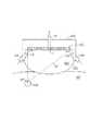
図1に本発明の第1の実施形態による超音波治療装置のブロック図を示す。アプリケータ1は、治療用強力超音波を集束的に発生する治療用超音波発生源2と、治療用強力超音波を治療用超音波発生源2から患者3までロス少なく導くカップリング液4と、このカップリング液4を密封する水袋5とを有している。治療に際しては、治療台10に患者3を固定してから、アプリケータ1を患者3の体表に乗せ、水袋5を超音波ゼリー等(図示せず)を介して患者3の皮膚に接触させる。(First embodiment)
FIG. 1 shows a block diagram of an ultrasonic therapy apparatus according to the first embodiment of the present invention. The
この治療用超音波発生源2の略中央部分には孔17が開けられ、ここに超音波プローブ8が挿入される。なお、この超音波プローブ8が治療用超音波発生源2の外側についているアウトラインタイプであってもよい。ここでは前者の構造で説明する。超音波プローブ8は、アプリケータ1に対して取り外し可能でも良いし、上記孔17に固定されていても良い。この超音波プローブ8は、前後方向のスライドと、軸回転移動が可能なように設けられている。これらスライドや軸回転の動きは、手動又は制御回路11とプローブ位置制御回路13の制御により実現される。 A
超音波診断装置14は、超音波プローブ8を介して患者3の断面をイメージング用超音波で走査し、治療用協力超音波の焦点7を含む断面の断層像を再構成し、CRT(図示せず)に表示できるように構成されている。また、超音波診断装置14は、断層像上に焦点7の位置をマーカで表示できるように構成されている。この機能を利用して、断層像上で体内の治療対象(結石や治療対象)6の位置を確認しながら、焦点7が治療対象6に一致するようにアプリケータ1や患者3を移動させることができる。治療対象6と焦点7の一致を断層像上で確認した後、駆動回路12で治療用超音波発生源2を駆動して強力超音波を照射し、超音波焦点7に存在している治療対象6を治療する。また、術者は、断層像から治療計画を立てたり、強力超音波照射前と照射後の体内の超音波画像を比較することにより、治療効果を確認したりできる。 The ultrasonic
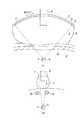
図2(a)に治療用超音波発生源2をその焦点7側から見た図を示している。図3(a)に治療用超音波発生源2の縦断面図を示し、同図(b)に治療用超音波発生源2の横断面図を示している。治療用超音波発生源2は、治療用強力超音波を肋骨16の隙間から治療対象に照射することが可能なように、比較的薄い、例えば肋骨間通過時の厚さが20mm以下の略扇状(又は薄いくさび形状)の治療用強力超音波を照射することができるように構成されている。具体的には、従来と同様に複数のピエゾ素子が球殻状にアレンジされていて、その中の幾つかのピエゾ素子だけを選択的に駆動して、結果的に扇状にも治療用強力超音波を照射するようにしてもよいし、扇状の治療用強力超音波だけを専門的に照射できるように治療用超音波発生源2を構成するようにしてもよい。ここでは後者の例について説明する。 FIG. 2A shows a view of the therapeutic ultrasonic
なお、上記略扇状は、従来の円錐形とは明確に区別される。つまり円錐形とはどのように縦断面を入れても、その断面形状がほぼ同じ扇形状(狭角が同じ)を示すのに対して、上記略扇状では、厚み方向でも幅方向でもその断面は扇形状になるが、厚み方向の断面の扇の狭角は、幅方向の断面の扇の狭角より非常に小さい、つまり非常に薄いくさび形状として表される。 The substantially fan shape is clearly distinguished from a conventional conical shape. In other words, the conical shape shows the same fan shape (same narrow angle) regardless of how the vertical cross section is inserted, whereas the above fan shape has the same cross section in both the thickness and width directions. Although it has a fan shape, the narrow angle of the fan in the cross section in the thickness direction is expressed as a wedge shape that is much smaller than the narrow angle of the fan in the cross section in the width direction.
超音波発生源2は、一定の曲率で長軸方向に湾曲している略短冊状又は略楕円状のフレーム9の内側に、図2(a)に示すようにフレーム9と同形に加工された1つのピエゾ素子21が貼り付けられ、または同図(b)に示すように複数のピエゾ素子22が一列又は多列にアレイされて構成されている。焦点7の位置は、フレーム9の曲率に従って超音波発生源2の位置に対して幾何学的に決まる。このピエゾ素子21(又は22)の開口面の最大幅は、例えば肋骨間通過時の厚さが20mm以下の扇状の治療用強力超音波を発生するように、例えば30mm以下に設けられる。 The ultrasonic
なお、焦点サイズをより局小化させるために、フレーム9は短軸方向にも長軸方向と同じ一定の曲率で湾曲していることが好ましい。 In order to further reduce the focal spot size, the
図2(c)に示すように、このような治療用超音波発生源2の略中央部分にはプローブ8を挿入するための孔17が開けられている。治療用超音波発生源2の角は、角張っていてもよいし、丸められていてもよい。 As shown in FIG. 2 (c), a
このように本実施形態では、比較的薄い扇状で治療用強力超音波を照射することができるので、肋骨16で遮蔽されることなく、この肋骨16の隙間から治療用強力超音波を治療対象6に到達させることができる。 As described above, in this embodiment, the therapeutic ultrasonic waves can be irradiated in a relatively thin fan shape, so that the therapeutic ultrasonic waves can be applied to the
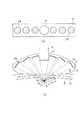
なお、図4(a),(b)に示すように、同様の形状の超音波発生源2を、2つ又はそれ以上設けて、複数の肋骨の隙間から、治療対象6に向けて治療用強力超音波を照射するようにしてもよい。この場合、超音波治療装置は治療用強力超音波それぞれの焦点が一致するように複数の超音波発生源2の角度を個別に調整するための構造及び制御回路を有している。 As shown in FIGS. 4 (a) and 4 (b), two or more ultrasonic
また、図5(a),(b)に示すように、複数の球殻状のピエゾ素子24をフレーム9に設けるようにしてもよい。この場合、複数の球殻状のピエゾ素子24は、それぞれの焦点(Fa,Fb,…Ff)が一カ所に集まるように、それぞれの角度が調整されてフレーム9に設けられている。 Further, as shown in FIGS. 5A and 5B, a plurality of spherical shell-shaped
(第2の実施形態)
図6に第2の実施形態による超音波治療装置の構成図を示している。図7は図6の超音波発生源2’の縦断面図である。これらの図において、図1と同じ部分には同じ符号を付して詳細な説明は省略する。(Second Embodiment)
FIG. 6 shows a configuration diagram of an ultrasonic therapy apparatus according to the second embodiment. FIG. 7 is a longitudinal sectional view of the ultrasonic
第1実施形態と同様に一定の曲率で長軸方向に湾曲している短冊状のフレーム9の内側に、複数の円板状のピエゾ素子25が一列にアレイされいる。このピエゾ素子25は、円板状でなくても、球殻状であってもよい。球殻状である場合は、図8に示すようなはめ込み式の振動子(符号Pは振動子、符号20は枠)で患部6の深さ応じて焦点7’を調整すべく、開口角の異なる振動子を選択して用いることが考えられる(図8(a)参照)。図8に示すように球殻状のピエゾ素子本体Pを枠20で補強することが好ましい。ピエゾ素子25の開口径は、第1実施形態と同様に、最大厚が20mm以下の扇状の治療用超音波が得られるように、約20mm以下であることが好ましい。 As in the first embodiment, a plurality of disk-shaped piezo elements 25 are arrayed in a row inside a strip-shaped
これらピエゾ素子25はそれぞれ個別に角度調節器18に支持されて、向きが個別に自由に変えられるようになっている。それぞれの向きを制御することにより、図7に示すように、アプリケータ1を固定した状態のままで、焦点7’の深さや方位を自由に変更することができる。この制御は、ポインタ22を介して断層上に指定された治療対象6の深さや方位に従って、振動子角度制御回路19により実現される。 These piezo elements 25 are individually supported by the
本実施形態によれば、第1実施形態の効果に加えて、アプリケータ1を固定した状態のままで、焦点7’の深さや方位を自由に変更することができる。 According to the present embodiment, in addition to the effects of the first embodiment, the depth and orientation of the
なお、この効果は、いわゆるフェーズドアレイでも得ることができる。この場合は、複数の平板状のピエゾ素子が一列にアレンジされており、これらの複数の平板状のピエゾ素子それぞれの駆動タイミングを、それぞれのピエゾ素子からの超音波が所望の深さの一点で集束するように、図9の位相制御回路26により個別に制御することにより実現される。 This effect can also be obtained with a so-called phased array. In this case, a plurality of plate-like piezo elements are arranged in a line, and the drive timing of each of the plurality of plate-like piezo elements is determined at a single point with a desired depth of ultrasonic waves from each of the piezo elements. It is realized by controlling individually by the
なお、これまでフレーム9の形状は短冊状として説明してきたが、図10に示すように、球殻状のフレーム27であってもよい。この場合、水袋5の取り付けや、水袋5を体表に固定する場台には、フレーム27が円形の方が安定性が良いと考えられるからである。 Although the shape of the
(第3の実施形態)
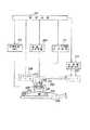
図13に第3の実施形態による超音波治療装置の構成を示している。図14(a)に、図13のアプリケータ101の断面を示している。アプリケータ101は、治療用強力超音波を照射する球殻状の治療用超音波発生源102と、強力超音波を患者103まで導くカップリング液104と、該カップリング液104を保持する水袋105とを有している。治療用超音波発生源102は、例えば球殻状のフレームの内面に複数の振動子(ピエゾ素子)が稠密に貼り付けられ、この振動子の背面に振動吸収用のバッキング材106が設けられてなる。(Third embodiment)
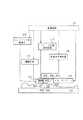
FIG. 13 shows the configuration of an ultrasonic therapy apparatus according to the third embodiment. FIG. 14A shows a cross section of the
カップリング液循環系120は、水袋105中のカップリング液104を吸水し、吸水したカップリング液104を冷却した後、水袋105中に戻すことができるように構成されている。このような循環により、カップリング液104により、超音波発生源102を冷却することができる。 The coupling
治療に際しては、治療台119に患者103を固定してから、アプリケータ101を患者103の体表に乗せ、水袋105を超音波ゼリー等(図示せず)を介して患者103の皮膚に接触させる。 In the treatment, the
アプリケータ101の略中央部分には孔125が開けられ、ここに超音波プローブ113が挿入されている。超音波プローブ113は、アプリケータ101に対して取り外し可能でも良いし、アプリケータ101に固定されていても良い。超音波診断装置116は、この超音波プローブ113を介して患者103の断面を走査し、得られたエコー信号に基づいて当該断面に関する断層像を再構成し、この断層像を表示する。 A
超音波プローブ113は、前後方向のスライドと、回転移動が可能なように設けられていて、制御回路114とプローブ位置制御回路117の制御により移動できる。また、手動で移動させることも可能である。 The
超音波診断装置116のCRT(図示せず)には超音波焦点107の位置がマーカ表示されるようになっており、超音波画像上で体内の治療対象108の位置を確認しながら、超音波焦点107が治療対象108に一致するようにメカニカルアーム118を介してアプリケータ101を移動し、又は患者103を移動させることができる。 The CRT (not shown) of the ultrasonic
治療対象108と焦点107の一致を超音波診断装置116で確認した後、駆動回路115で治療用超音波発生源102を駆動して治療用強力超音波を照射し、超音波焦点107と一致した治療部位108を高温に加熱して治療する。また、術者は、超音波診断装置116による体内画像により治療計画を立てたり、強力超音波照射前と照射後の体内の超音波画像を比較することにより、治療効果を確認したりできる。 After the coincidence between the
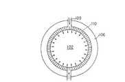
次に本実施形態の特徴であるカップリング液循環系120について説明する。図14(a)に示すように、超音波発生源102の略中央部分には、取水口111が開けられ、ここに吸水パイプ112が接続される。また、超音波発生源2の表面にカップリング液4を吹き付ける向きに、かつ治療用超音波のパスを遮蔽しないように、治療用超音波のパス122の外側の超音波発生源102の周縁部に、カップリング液104を吐出するための複数のノズル(吐出口)110が離散的に、又は円弧状の1つのノズルが設けられる(図16参照)。このノズル110には排水パイプ109が接続される。 Next, the coupling
このように取水口111とノズル110を設けたことにより、水袋105の中をカップリング液104は、超音波発生源2の周縁から頂上に向かって振動子表面をなぞるように流れる。この流れにより、超音波発生源2(振動子)を効率的に冷却することができる。 By providing the water intake port 111 and the
図14(b)には、カップリング液循環系120の構成を示している。水袋105のカップリング液104の量は、焦点107が治療対象108に一致するようにその深さに応じて予め調整されている。したがって循環中も水袋105中のカップリング液104の量を一定に保つ必要がある。このために吸水用と排水用の2つのポンプ系統を有し、これら2系統の回転軸が共通していて、格別な制御を不要にして吸水量と同じ量を排水するいわゆる二連式チュービングポンプ131が循環用ポンプとして採用されている。この二連式チュービングポンプ131の働きにより、水袋105と冷却装置132の保温リザーバータンクとの間でカップリング液104が循環される。この保温リザーバータンク内のカップリング液104は常に冷却状態(例えば10゜C)に保たれていて、この冷たいカップリング液104を水袋105に戻すことができるようになっている。また、この保温リザーバータンク内のカップリング液104の脱気状態を良好に維持するために、保温リザーバータンクと脱気装置133との間でもカップリング液104が循環するようになっている。 FIG. 14B shows the configuration of the coupling
上述したように水袋105内の液量を調整するために、この二連式チュービングポンプ131とは別に、小型チュービングポンプ134の取水口が排水パイプ109の一部に取り付けられている。そして、小型チュービングポンプ134で取水したカップリング液104を、保温リザーバータンクに排水するようになっている。 As described above, in order to adjust the amount of liquid in the
このように本実施形態によれば、簡易な構成にして効果的に超音波発生源102(振動子)を冷却することができる。 As described above, according to the present embodiment, the ultrasonic wave generation source 102 (vibrator) can be effectively cooled with a simple configuration.
なお、吸水ノズルや吐出口110を次のように工夫してもよい。例えば図15に示すように、排水パイプ109を緩やかに曲げることにより、ポンプ131にかかる負荷を多少といえども軽減することができる。また、図17に示すように排水ノズル110を超音波発生源102の周縁全域に配置しなくても、対抗する2カ所に設けるだけでもよいかもしれない。また、吸水口111を図18に示すように超音波発生源102の周縁に配置してもよい。また、図19に示すように排水ノズル110をカップリング液104が超音波発生源102に対して斜め上方に吹き出すように配置してもよい。この場合、吹き出されたカップリング液4は、超音波発生源102の内面を周回しながら吸水口111まで上がっていくように流れ、超音波発生源102を効果的に冷却することができる。 In addition, you may devise the water absorption nozzle and the
また、超音波発生源102の発熱は、常にカップリング液4に接触している表面(強力超音波を放射する面)だけでなく、裏面(通常は空気バッキング)にも伝わる。そこで超音波発生源102の裏面の冷却にも考慮して、図20に示すように、この裏側にもカップリング液104を循環させるようにしてもよい。超音波発生源102の裏面は駆動電極側になるため、表面(アース)とは絶縁する必要がある。このときの絶縁体として、放熱性を低下させるような熱伝導性の悪い材料を用いることは避けるべきである。また、超音波の裏面への放出をなるべく小さくするために、超音波発生源102の音響インビータンスと大きく異なる音響インピーダンスを持つ材料が好ましい。これらのことから、図20のように、絶縁体として厚さの薄い空気層123を用い、これを振動子の裏面とは絶縁された薄いアルミ板124で覆い、その上にカップリング液104を循環させるもの等が考えられる。または、空気層123の代わりに熱伝導性の良いグリース(図示せず)を詰めたものでも良い。図20に示す実施形態では、カップリング液104は排水パイプ109を通り、吐出ノズル110から水袋105内に入り、超音波発生源102の表面を冷却し、吸水口111から超音波発生源102の裏面に出て、超音波発生源102の裏面を冷却した後、吸水パイプ112から吸水される。なお、カップリング液104が、超音波発生源102の表面と裏面を通る構造であれば、図20に示した構造に限られたものではない。 Further, the heat generated by the ultrasonic
(第4の実施形態)
図21に第4の実施形態の主要部であるところのバッキング材の断面を示している。第4の実施形態では、背面側への振動を吸収するために振動子の背面に設けられているバッキング材126を使って、超音波発生源102の冷却効果をより高めようとするものであり、これ単独で又は第3の実施形態と併用されるべきものである。(Fourth embodiment)
FIG. 21 shows a cross section of the backing material, which is the main part of the fourth embodiment. In the fourth embodiment, the
つまりバッキング材126の熱容量を利用して、超音波発生源102で発生した熱が小熱容量の超音波発生源102内に溜まって高温になるということを軽減する。このバッキング材126の材料としては、ピエゾ素子として用いられるPZTセラミックスの熱伝導率が2〜4W/(m・K)であることから、熱伝導率が10W/(m・K)以上であるアルミニウム、銀、銅等の金属を選択することにより、熱の拡散が素早く行われるようになる。 That is, the heat capacity of the
尚、バッキング材126に金属を使用する場合の周囲との絶縁の取りかたは、図21のような超音波発生源102とバッキング材126の間に空気層128等の絶縁体を入れ、バッキング材126には治療用超音波発生源102に電力を投入するためのケーブル127を通すための孔129を設けてもよいし、図22のように、バッキング材126を治療用超音波発生源2に直に接触させ、これを電極とみなしてケーブル127を接続してもよい。この場合は、バッキング材126の周りに、絶縁体130を設けて、周囲との絶縁をとることが考えられる。 When using metal for the
また、図23に示すように、超音波発生源102´を構成する複数のピエゾ素子が平面的に配列され、遅延制御により任意の位置に焦点107を形成することができる場合も、カップリング液104による超音波発生源102′の冷却は同様に行える。 As shown in FIG. 23, the coupling liquid is also used when a plurality of piezoelectric elements constituting the ultrasonic
上述した実施形態のようにカップリング液を循環させる場合、水袋内のカップリング液量を一定に保つことが不可欠になってくる。これは、排水量と注水量とがアンバランスとなり水袋内のカップリング液量が変化すると、それに応じて、伸縮性を有している水袋は大きさが変わってしまい、これによって、水袋が破損し、水漏事故につながる恐れがあり、これ程の事態に至らないまでも水袋と体表との密着性が低下して治療波が体内に届かなくなってしまったり、また治療波焦点が患部から外れてしまう危険性がある。次に説明する第5の実施形態は、このような事態を防止することを目的としてなされたものである。 When the coupling liquid is circulated as in the embodiment described above, it is essential to keep the amount of the coupling liquid in the water bag constant. This is because when the amount of drainage and the amount of water injected become unbalanced and the amount of coupling liquid in the water bag changes, the size of the elastic water bag changes accordingly. May lead to water leakage accidents, and even if this situation does not occur, the adhesion between the water bag and the body surface will decrease and the treatment wave will not reach the body, and the treatment wave focus will There is a risk of detachment from the affected area. The fifth embodiment to be described next is made for the purpose of preventing such a situation.
(第5の実施形態)
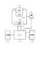
図24に本発明の第5の実施形態による超音波治療装置の構成を示す。アプリケータ201は、治療用強力超音波を照射する超音波発生源202と、超音波発生源202に取り付けられた水袋205と、超音波発生源202と水袋205との間に封入され、強力超音波を患者3まで損失少なく導くためのカップリング液204とを有している。治療する際は、治療台228に患者203を固定してから、アプリケータ201を患者203の体表に乗せ、水袋205を超音波ゼリー等(図示せず)を介して患者203の皮膚に接触させる。(Fifth embodiment)
FIG. 24 shows the configuration of an ultrasonic therapy apparatus according to the fifth embodiment of the present invention. The
超音波発生源202は、図25に示すように、1枚又は複数の超音波振動子が、球殻形状に形成され、または球殻形状に配列されていて、それから発生した超音波が、球殻の曲率で幾何学的に決まる焦点206に集束するようになっている。アプリケータ201は、制御回路7に制御されるメカニカルアーム8により電動で又は手動でメカ的に任意の姿勢で任意の向きに自由に移動できるようになっている。 As shown in FIG. 25, the ultrasonic
このアプリケータ201には、患者203の体内の超音波画像を得て焦点206と患部212との位置合わせに使うために、超音波診断装置209に接続された超音波プローブ210が備えられている。超音波プローブ210は、アプリケータ201に対して取り外し可能でも良いし、アプリケータ201に固定されていても良い。ここでは、超音波発生源202の略中央部に孔を開け、ここに超音波プローブ210を挿入するようになっている。超音波プローブ210は、前後方向のスライドと、回転移動が可能なように構成されていて、制御回路207とプローブ位置制御回路211の制御により移動できる。また、手動で移動させることも可能である。 The
超音波診断装置209のCRT(図示せず)には超音波画像と共に超音波焦点206の位置を表す焦点マーカが表示されるようになっており、超音波画像(図示せず)上で体内の患部212の位置を確認しながら、超音波焦点206が患部212に一致するようにアプリケータ201や患者203を移動できるようになっている。 A CRT (not shown) of the ultrasound
患部212と焦点206の一致を超音波診断装置209で確認した後、駆動回路(群)213で超音波発生源202を駆動して強力超音波を照射し、超音波焦点206と一致した患部212を高温に加熱して治療する。また、術者は、超音波診断装置209による体内画像(図示せず)により治療計画を立てたり、強力超音波照射前と照射後の体内の超音波画像を比較することにより、治療効果を確認したりできる。 After the coincidence between the
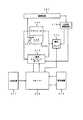
ところで、患部212に連続波を照射する際に超音波発生源202が発熱し、この熱によりカップリング液204の温度も上昇するため、治療中は超音波発生源202と、カップリング液204の冷却が必要である。また、強力な超音波を照射する際に発生するキャビテーションの影響を防ぐため、カップリング液204の十分な脱気が必要である。このため、本実施形態では、図26に示すように、リザーバ216に貯水されているカップリング液204を、冷却装置217により冷却し、また、脱気装置18により例えば溶存酸素量2.5mg/l以下に脱気するようにしている。 By the way, the ultrasonic
また、超音波発生源202又はこれに水袋205を固定するためのバッキング材に設けたカップリング液204の注水口219及び排水口220を介して、カップリング液204をアプリケータ201とリザーバ216との間で循環させるために、入出量の整合性に優れている二連式チュービングポンプ(主ポンプ)215が設けられている。尚、この例ではカップリング液204の循環に二連式チュービングポンプを採用しているが、これは複数のポンプでアプリケータ201への注水、排水を行ってもよい。 Further, the
ところで、上述したように主に注水量と排水量との不整合により、伸縮性のある水袋205の大きさが変化してしまうという問題に対して、二連式のチュービングポンプ215を採用することの他に、次のような対策を講じている。 By the way, as described above, the
この対策は、図27に示すように、アプリケータ201からのカップリング液204の排水量と、アプリケータ201へのカップリング液204の注水量との少なくとも一方を微調整するための補助ポンプ221を設け、またアプリケータ201の注水口219と排水口220にそれぞれ流量計222,223を配備して、アプリケータ201に対する注水量と排水量とを常時又は一定の時間置きに個別に計測し、そしてこれらの流量計222,223で計測した注水量データと排水量データを制御回路207で比較し、この制御回路207からの注水量と排水量との差のデータに従って水回路制御回路214で注水量と排水量とが高精度で一致するように補助ポンプ221の出力を制御するようにしたものである。 As shown in FIG. 27, this measure includes an auxiliary pump 221 for finely adjusting at least one of the drainage amount of the
次に循環動作について詳細に説明する。カップリング液204の循環動作は、治療用超音波の発生期間中に連続的に行っていもよいが、焦点206の位置がずれる危険性を秘めている循環動作は、できるだけ少ない方が好ましい。このための方法を次に説明する。 Next, the circulation operation will be described in detail. Although the circulation operation of the
長時間の治療中にカップリング液204の循環を継続させるとき、この長時間の間ずっと、主ポンプ215の吸い込み量と吐き出し量とのアンバランスを取ることは非常に困難と言える。このバランスが崩れると、水袋205の大きさが安定しなくなるため、超音波焦点206がずれたりする可能性もある。そこで、アプリケータ201内の水温が危険値(上限値)に達するまでは、循環動作を停止させておく、つまりアプリケータ201内の水温が上限値を越えている間だけ、循環動作を実行する方法が考えられる。 When the circulation of the
具体的には、図28に示すように、水袋5の内部に熱電体等を使った温度センサ224を設け、水袋205内のカップリング液204の水温を、場合によっては超音波発生源202の表面温度と共に、常時又は一定の時間を置いて計測する。そして、この水温データを、制御回路207で上限値と比較し、この制御回路207からの比較結果に従って、アプリケータ201内の水温が上限値を越えているとき、主ポンプ215を起動し、水温が上限値を下回ったとき主ポンプ215の動作を停止させるように、水回路制御回路214で主ポンプ215を制御する。もちろん、この循環中には、流量計222,223によりアプリケータ201への注水量と排水量は監視されていて、両者が一致するように制御されている。 Specifically, as shown in FIG. 28, a temperature sensor 224 using a thermoelectric material or the like is provided inside the
なお、水温が上限値を超えたとき、制御回路207が光や音等の手段を使って警告を発し、術者が手動でカップリング液204の循環をスタートさせるようにしてもよい。また、カップリング液204が上限値を越えた、越えないに関わらず、一定の時間毎に一定の期間だけ周期的にカップリング液204の循環を行うようにしてもよい。さらに、循環動作を一定時間継続しても、水温が上限値を下回らないときには、異常事態であると判断して、それを制御回路207で光や音等の手段を使って術者に伝達し、緊急停止等の何らかの対処を促すようにしてもよい。 Note that when the water temperature exceeds the upper limit value, the
さらに、以上のように補助ポンプ221を使うなどしてカップリング液204の注水量、排水量の整合をとって、水袋205の大きさの変動を高精度で抑えるようにしているが、この精度をさらに向上させるために、実際に水袋205の大きさ(径)の変動を、張力センサ等を使って計測するようにしてもよい。この場合、張力センサで常時又は一定の時間を置いて水袋205の張力を計測する。そして、この張力データを、制御回路207で直前又は所定時間前の張力と比較し、この制御回路207からの比較結果に従って水回路制御回路214は、現在の張力が直前の張力より高いとき、主ポンプ215の出力を若干低下させ、現在の張力が直前の張力より低いとき、主ポンプ215の出力を若干高くするように、主ポンプ215を制御する。なお、張力センサの代わりに、圧力センサ等の他の原理のセンサでもよい。水袋205の張力の変化はカップリング液204の増減だけでなく、水袋205の形状の変化等によっても生じるため、基準値を超えると警告を発するだけとし、流量の増減の判断は術者が行うようにしてもよい。 Furthermore, as described above, by using the auxiliary pump 221 and the like, the amount of water injected and the amount of drainage of the
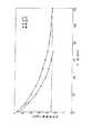
次に、効果的な脱気方法について実験結果に基づいて説明する。図29には、溶存酸素量が飽和状態から2.5mg/lまで低下するのに要する脱気時間の水温に対する依存性を示している。水中の飽和溶存酸素量は水温によって変化し、水温が高いほど少ないので、実験結果より、水温が高い状態から脱気を開始した方が、水温が低い状態から脱気を開始するよりも、脱気に要する時間が少なくてすむことがわかった。 Next, an effective degassing method will be described based on experimental results. FIG. 29 shows the dependence of the degassing time required for the dissolved oxygen amount to decrease from the saturated state to 2.5 mg / l with respect to the water temperature. The amount of saturated dissolved oxygen in the water varies depending on the water temperature, and the lower the water temperature, the smaller the amount of oxygen.From the experimental results, it is better to start degassing from a state where the water temperature is higher than starting from the state where the water temperature is lower It turns out that less time is needed.
そこで、本実施形態では、脱気を効率的に行って、それに要する時間を短縮するために、図30に示すように、水温センサ227をリザーバ216内に設ける。そして、例えば通常の水道水でリザーバ216を満たし、そのときの水温を計測する。この水温データを、制御回路207で設定値(例えば、摂氏20度)と比較し、水温が設定値(摂氏20度)を下回っているとき、水温制御回路226を制御して、水温を摂氏20度まで上昇させる。この状態で、水道水を、例えば溶存酸素量が2.5mg/l以下になるまで脱気することで、この脱気に要する時間を短縮して早期に治療を開始することができる。ここで、脱気時の水温を摂氏20度としたのは、脱気終了後に、治療時のカップリング液204の水温条件である例えば摂氏10゜まで冷却するための冷却時間とのかねあいを考慮して、脱気時間を短縮するために水温を余り高くしすぎると、脱気時間事態は短縮され得るが、その代わりに冷却時間が長くなり、結局治療開始までの時間が長くなってしまいかねないからである。Therefore, in the present embodiment, a
なお、以上の説明で超音波発生源202を球殻状のものとしたが、これは平板振動子が平面状に並んだ、フェーズドアレイでもよい。また、超音波加熱治療装置について述べたが、超音波結石破砕装置に用いてもよい。 In the above description, the ultrasonic
なお、本発明は上記実施形態そのままに限定されるものではなく、実施段階ではその要旨を逸脱しない範囲で構成要素を変形して具体化できる。また、上記実施形態に開示されている複数の構成要素の適宜な組み合わせにより、種々の発明を形成できる。例えば、実施形態に示される全構成要素から幾つかの構成要素を削除してもよい。さらに、異なる実施形態にわたる構成要素を適宜組み合わせてもよい。 Note that the present invention is not limited to the above-described embodiment as it is, and can be embodied by modifying the components without departing from the scope of the invention in the implementation stage. In addition, various inventions can be formed by appropriately combining a plurality of constituent elements disclosed in the embodiment. For example, some components may be deleted from all the components shown in the embodiment. Furthermore, constituent elements over different embodiments may be appropriately combined.
1…アプリケータ、2…治療用超音波発生源、3…患者、4…カップリング液、5…水袋、6…治療対象、7…超音波焦点、8…超音波プローブ、9…フレーム、10…寝台、11…制御回路、12…駆動回路、13…プローブ位置制御回路、14…超音波診断装置、15…メカニカルアーム。 DESCRIPTION OF
Claims (6)
Translated fromJapanese前記カップリング液を貯水するリザーバと、
前記カップリング液を前記アプリケータと前記リザーバとの間で循環させるための主ポンプと、
前記水袋からのカップリング液の排水量と、前記水袋へのカップリング液の注水量との少なくとも一方を微調整するための補助ポンプとを具備することを特徴とする超音波治療装置。An ultrasonic wave generated by an ultrasonic wave generation source is introduced into the subject via a coupling liquid sealed between the ultrasonic wave generation source and a water bag so as to treat an affected area in the subject. A configured applicator;
A reservoir for storing the coupling liquid;
A main pump for circulating the coupling liquid between the applicator and the reservoir;
An ultrasonic therapy apparatus comprising: an auxiliary pump for finely adjusting at least one of a drainage amount of the coupling liquid from the water bag and a water injection amount of the coupling liquid to the water bag.
Priority Applications (1)
| Application Number | Priority Date | Filing Date | Title |
|---|---|---|---|
| JP2007062596AJP2007144225A (en) | 1997-03-03 | 2007-03-12 | Ultrasonic therapy device |
Applications Claiming Priority (2)
| Application Number | Priority Date | Filing Date | Title |
|---|---|---|---|
| JP4806697 | 1997-03-03 | ||
| JP2007062596AJP2007144225A (en) | 1997-03-03 | 2007-03-12 | Ultrasonic therapy device |
Related Parent Applications (1)
| Application Number | Title | Priority Date | Filing Date |
|---|---|---|---|
| JP25067297ADivisionJP4044182B2 (en) | 1997-03-03 | 1997-09-16 | Ultrasonic therapy device |
Publications (1)
| Publication Number | Publication Date |
|---|---|
| JP2007144225Atrue JP2007144225A (en) | 2007-06-14 |
Family
ID=38206275
Family Applications (1)
| Application Number | Title | Priority Date | Filing Date |
|---|---|---|---|
| JP2007062596APendingJP2007144225A (en) | 1997-03-03 | 2007-03-12 | Ultrasonic therapy device |
Country Status (1)
| Country | Link |
|---|---|
| JP (1) | JP2007144225A (en) |
Cited By (16)
| Publication number | Priority date | Publication date | Assignee | Title |
|---|---|---|---|---|
| JP2012115585A (en)* | 2010-12-03 | 2012-06-21 | Tohoku Univ | Array type ultrasonic transmitter |
| WO2012153888A1 (en)* | 2011-05-12 | 2012-11-15 | 알피니언메디칼시스템 주식회사 | Applicator for high intensity focused ultrasound |
| JP2013529245A (en)* | 2010-05-25 | 2013-07-18 | セラクリオン・ソシエテ・パル・アクシオン・サンプリフィエ | Ultrasonic coupling fluid and container |
| JP2016533784A (en)* | 2013-10-11 | 2016-11-04 | ソナケアー メディカル,エルエルシー | Focused ultrasound therapy using fluid bladder |
| JP2018118092A (en)* | 2012-04-30 | 2018-08-02 | ザ リージェンツ オブ ザ ユニヴァシティ オブ ミシガン | Ultrasound treatment system and method for designing and manufacturing an ultrasound system |
| FR3065571A1 (en)* | 2017-04-24 | 2018-10-26 | Edap Tms France | METHOD FOR COOLING AN ULTRASONIC PROBE AND PROBE INCLUDING SUCH COOLING |
| US10780298B2 (en) | 2013-08-22 | 2020-09-22 | The Regents Of The University Of Michigan | Histotripsy using very short monopolar ultrasound pulses |
| US11058399B2 (en) | 2012-10-05 | 2021-07-13 | The Regents Of The University Of Michigan | Bubble-induced color doppler feedback during histotripsy |
| US11135454B2 (en) | 2015-06-24 | 2021-10-05 | The Regents Of The University Of Michigan | Histotripsy therapy systems and methods for the treatment of brain tissue |
| US11364042B2 (en) | 2005-09-22 | 2022-06-21 | The Regents Of The University Of Michigan | Histotripsy for thrombolysis |
| US11648424B2 (en) | 2018-11-28 | 2023-05-16 | Histosonics Inc. | Histotripsy systems and methods |
| JP2023084945A (en)* | 2021-12-08 | 2023-06-20 | ソニア・セラピューティクス株式会社 | HIFU irradiation equipment |
| US11813485B2 (en) | 2020-01-28 | 2023-11-14 | The Regents Of The University Of Michigan | Systems and methods for histotripsy immunosensitization |
| CN118961895A (en)* | 2024-08-16 | 2024-11-15 | 无锡领声科技有限公司 | Solid coupled ultrasonic testing method |
| US12318636B2 (en) | 2022-10-28 | 2025-06-03 | Histosonics, Inc. | Histotripsy systems and methods |
| US12343568B2 (en) | 2020-08-27 | 2025-07-01 | The Regents Of The University Of Michigan | Ultrasound transducer with transmit-receive capability for histotripsy |
Citations (2)
| Publication number | Priority date | Publication date | Assignee | Title |
|---|---|---|---|---|
| JPS61191429A (en)* | 1985-02-20 | 1986-08-26 | Kayaba Ind Co Ltd | Hydraulic control device of hydraulic drive vehicle |
| JPH08126649A (en)* | 1994-10-31 | 1996-05-21 | Toshiba Corp | Ultrasonic therapy equipment |
- 2007
- 2007-03-12JPJP2007062596Apatent/JP2007144225A/enactivePending
Patent Citations (2)
| Publication number | Priority date | Publication date | Assignee | Title |
|---|---|---|---|---|
| JPS61191429A (en)* | 1985-02-20 | 1986-08-26 | Kayaba Ind Co Ltd | Hydraulic control device of hydraulic drive vehicle |
| JPH08126649A (en)* | 1994-10-31 | 1996-05-21 | Toshiba Corp | Ultrasonic therapy equipment |
Cited By (35)
| Publication number | Priority date | Publication date | Assignee | Title |
|---|---|---|---|---|
| US12303152B2 (en) | 2005-09-22 | 2025-05-20 | The Regents Of The University Of Michigan | Histotripsy for thrombolysis |
| US12150661B2 (en) | 2005-09-22 | 2024-11-26 | The Regents Of The University Of Michigan | Histotripsy for thrombolysis |
| US11701134B2 (en) | 2005-09-22 | 2023-07-18 | The Regents Of The University Of Michigan | Histotripsy for thrombolysis |
| US11364042B2 (en) | 2005-09-22 | 2022-06-21 | The Regents Of The University Of Michigan | Histotripsy for thrombolysis |
| JP2013529245A (en)* | 2010-05-25 | 2013-07-18 | セラクリオン・ソシエテ・パル・アクシオン・サンプリフィエ | Ultrasonic coupling fluid and container |
| JP2012115585A (en)* | 2010-12-03 | 2012-06-21 | Tohoku Univ | Array type ultrasonic transmitter |
| WO2012153888A1 (en)* | 2011-05-12 | 2012-11-15 | 알피니언메디칼시스템 주식회사 | Applicator for high intensity focused ultrasound |
| KR101259381B1 (en)* | 2011-05-12 | 2013-04-30 | 알피니언메디칼시스템 주식회사 | Applicator for HIFU |
| JP2018118092A (en)* | 2012-04-30 | 2018-08-02 | ザ リージェンツ オブ ザ ユニヴァシティ オブ ミシガン | Ultrasound treatment system and method for designing and manufacturing an ultrasound system |
| JP2019146980A (en)* | 2012-04-30 | 2019-09-05 | ザ リージェンツ オブ ザ ユニヴァシティ オブ ミシガン | Ultrasound therapy system, methods of designing and manufacturing ultrasound system |
| US11058399B2 (en) | 2012-10-05 | 2021-07-13 | The Regents Of The University Of Michigan | Bubble-induced color doppler feedback during histotripsy |
| US11819712B2 (en) | 2013-08-22 | 2023-11-21 | The Regents Of The University Of Michigan | Histotripsy using very short ultrasound pulses |
| US10780298B2 (en) | 2013-08-22 | 2020-09-22 | The Regents Of The University Of Michigan | Histotripsy using very short monopolar ultrasound pulses |
| US12350525B2 (en) | 2013-08-22 | 2025-07-08 | The Regents Of The University Of Michigan | Histotripsy using very short ultrasound pulses |
| JP2016533784A (en)* | 2013-10-11 | 2016-11-04 | ソナケアー メディカル,エルエルシー | Focused ultrasound therapy using fluid bladder |
| US11135454B2 (en) | 2015-06-24 | 2021-10-05 | The Regents Of The University Of Michigan | Histotripsy therapy systems and methods for the treatment of brain tissue |
| US12220602B2 (en) | 2015-06-24 | 2025-02-11 | The Regents Of The University Of Michigan | Histotripsy therapy systems and methods for the treatment of brain tissue |
| WO2018197795A1 (en) | 2017-04-24 | 2018-11-01 | Edap Tms France | Method for cooling an ultrasonic probe and probe including such cooling |
| JP2020521524A (en)* | 2017-04-24 | 2020-07-27 | エダップ テエムエス フランスEdap Tms France | Method for cooling an ultrasonic probe and probe including such cooling |
| US11364017B2 (en) | 2017-04-24 | 2022-06-21 | Edap Tms France | Method for cooling an ultrasonic probe and probe including such cooling |
| JP7142028B2 (en) | 2017-04-24 | 2022-09-26 | エダップ テエムエス フランス | Methods of cooling ultrasonic probes and probes containing such cooling |
| CN110546706A (en)* | 2017-04-24 | 2019-12-06 | Edap Tms法国公司 | Method for cooling an ultrasonic probe and probe comprising such cooling |
| CN110546706B (en)* | 2017-04-24 | 2023-10-20 | Edap Tms法国公司 | Method for cooling an ultrasonic probe and probe comprising such a cooling |
| FR3065571A1 (en)* | 2017-04-24 | 2018-10-26 | Edap Tms France | METHOD FOR COOLING AN ULTRASONIC PROBE AND PROBE INCLUDING SUCH COOLING |
| US11648424B2 (en) | 2018-11-28 | 2023-05-16 | Histosonics Inc. | Histotripsy systems and methods |
| US11980778B2 (en) | 2018-11-28 | 2024-05-14 | Histosonics, Inc. | Histotripsy systems and methods |
| US11813484B2 (en) | 2018-11-28 | 2023-11-14 | Histosonics, Inc. | Histotripsy systems and methods |
| US12420118B2 (en) | 2018-11-28 | 2025-09-23 | Histosonics, Inc. | Histotripsy systems and methods |
| US11813485B2 (en) | 2020-01-28 | 2023-11-14 | The Regents Of The University Of Michigan | Systems and methods for histotripsy immunosensitization |
| US12343568B2 (en) | 2020-08-27 | 2025-07-01 | The Regents Of The University Of Michigan | Ultrasound transducer with transmit-receive capability for histotripsy |
| JP7320297B2 (en) | 2021-12-08 | 2023-08-03 | ソニア・セラピューティクス株式会社 | HIFU irradiation equipment |
| JP2023084945A (en)* | 2021-12-08 | 2023-06-20 | ソニア・セラピューティクス株式会社 | HIFU irradiation equipment |
| US12318636B2 (en) | 2022-10-28 | 2025-06-03 | Histosonics, Inc. | Histotripsy systems and methods |
| US12390665B1 (en) | 2022-10-28 | 2025-08-19 | Histosonics, Inc. | Histotripsy systems and methods |
| CN118961895A (en)* | 2024-08-16 | 2024-11-15 | 无锡领声科技有限公司 | Solid coupled ultrasonic testing method |
Similar Documents
| Publication | Publication Date | Title |
|---|---|---|
| JP2007144225A (en) | Ultrasonic therapy device | |
| US7470241B2 (en) | Controlled high efficiency lesion formation using high intensity ultrasound | |
| US5601526A (en) | Ultrasound therapy apparatus delivering ultrasound waves having thermal and cavitation effects | |
| JP4295088B2 (en) | Therapeutic probe using focused ultrasound | |
| US5472405A (en) | Therapy apparatus for the treatment of pathological tissue with a catheter | |
| US8409099B2 (en) | Focused ultrasound system for surrounding a body tissue mass and treatment method | |
| RU2210409C2 (en) | System for focused action of high-intensity ultrasound for scanning and treatment of tumors | |
| US5624382A (en) | Method and apparatus for ultrasound tissue therapy | |
| US10806952B2 (en) | Therapeutic ultrasound apparatus and method | |
| US8611189B2 (en) | Acoustic coupler using an independent water pillow with circulation for cooling a transducer | |
| JPH05300910A (en) | Ultrasonic medical treatment system | |
| JP2010534076A (en) | An apparatus and method that applies non-invasive ultrasound to shape the body using skin contact cooling. | |
| JPH09173372A (en) | Urethra through type focal ultrasonic treatment device and method therefor | |
| JP2023130384A (en) | Systems, devices, and methods for treatment of nasal disorders | |
| JP4044182B2 (en) | Ultrasonic therapy device | |
| Mast et al. | Treatment of rabbit liver cancer in vivo using miniaturized image-ablate ultrasound arrays | |
| CN116870385A (en) | An ultrasonic catheter and an ultrasonic treatment device integrating mapping and ablation | |
| Lafon et al. | Optimizing the shape of ultrasound transducers for interstitial thermal ablation | |
| JP3322649B2 (en) | Ultrasound therapy equipment | |
| EP4619096A1 (en) | Ultrasound image-guided focused ultrasound systems and related methods | |
| JPH11155894A (en) | Ultrasonic therapy apparatus and irradiation condition setting method thereof | |
| JP3369504B2 (en) | Ultrasound therapy equipment | |
| JP2000237199A (en) | Ultrasound therapy equipment | |
| JP2001070333A (en) | Ultrasonic irradiation device | |
| Tavakkoli et al. | A laparoscopic HIFU probe with integrated phased array ultrasound imaging |
Legal Events
| Date | Code | Title | Description |
|---|---|---|---|
| A621 | Written request for application examination | Free format text:JAPANESE INTERMEDIATE CODE: A621 Effective date:20070312 | |
| A131 | Notification of reasons for refusal | Free format text:JAPANESE INTERMEDIATE CODE: A131 Effective date:20100126 | |
| A02 | Decision of refusal | Free format text:JAPANESE INTERMEDIATE CODE: A02 Effective date:20100615 |