JP2007144153A - Lumen traversing device - Google Patents
Lumen traversing deviceDownload PDFInfo
- Publication number
- JP2007144153A JP2007144153AJP2006299340AJP2006299340AJP2007144153AJP 2007144153 AJP2007144153 AJP 2007144153AJP 2006299340 AJP2006299340 AJP 2006299340AJP 2006299340 AJP2006299340 AJP 2006299340AJP 2007144153 AJP2007144153 AJP 2007144153A
- Authority
- JP
- Japan
- Prior art keywords
- tubular element
- tubular
- lumen
- distal
- tool
- Prior art date
- Legal status (The legal status is an assumption and is not a legal conclusion. Google has not performed a legal analysis and makes no representation as to the accuracy of the status listed.)
- Granted
Links
- 230000008602contractionEffects0.000claimsabstractdescription12
- 239000004744fabricSubstances0.000claimsdescription3
- 238000000034methodMethods0.000abstractdescription26
- 210000001035gastrointestinal tractAnatomy0.000abstractdescription8
- 210000000056organAnatomy0.000abstractdescription6
- 208000034693LacerationDiseases0.000abstractdescription2
- 239000000463materialSubstances0.000description23
- 230000002496gastric effectEffects0.000description6
- 230000007246mechanismEffects0.000description5
- 238000011282treatmentMethods0.000description5
- 230000007423decreaseEffects0.000description4
- 239000007943implantSubstances0.000description4
- 230000000968intestinal effectEffects0.000description3
- 229910001000nickel titaniumInorganic materials0.000description3
- 229910045601alloyInorganic materials0.000description2
- 239000000956alloySubstances0.000description2
- 210000000436anusAnatomy0.000description2
- 229920000249biocompatible polymerPolymers0.000description2
- 239000011248coating agentSubstances0.000description2
- 238000000576coating methodMethods0.000description2
- 239000003814drugSubstances0.000description2
- 210000003750lower gastrointestinal tractAnatomy0.000description2
- 229910052751metalInorganic materials0.000description2
- 239000002184metalSubstances0.000description2
- HLXZNVUGXRDIFK-UHFFFAOYSA-Nnickel titaniumChemical compound[Ti].[Ti].[Ti].[Ti].[Ti].[Ti].[Ti].[Ti].[Ti].[Ti].[Ti].[Ni].[Ni].[Ni].[Ni].[Ni].[Ni].[Ni].[Ni].[Ni].[Ni].[Ni].[Ni].[Ni].[Ni]HLXZNVUGXRDIFK-UHFFFAOYSA-N0.000description2
- 229920001778nylonPolymers0.000description2
- -1polyethylenePolymers0.000description2
- 230000001681protective effectEffects0.000description2
- 239000010935stainless steelSubstances0.000description2
- 229910001220stainless steelInorganic materials0.000description2
- 238000001356surgical procedureMethods0.000description2
- 210000002438upper gastrointestinal tractAnatomy0.000description2
- 239000004677NylonSubstances0.000description1
- 239000004698PolyethyleneSubstances0.000description1
- 239000004743PolypropyleneSubstances0.000description1
- 229910000639Spring steelInorganic materials0.000description1
- HZEWFHLRYVTOIW-UHFFFAOYSA-N[Ti].[Ni]Chemical compound[Ti].[Ni]HZEWFHLRYVTOIW-UHFFFAOYSA-N0.000description1
- 230000009471actionEffects0.000description1
- 238000004026adhesive bondingMethods0.000description1
- 238000002405diagnostic procedureMethods0.000description1
- 238000002674endoscopic surgeryMethods0.000description1
- 230000002708enhancing effectEffects0.000description1
- 230000006870functionEffects0.000description1
- 238000003780insertionMethods0.000description1
- 230000037431insertionEffects0.000description1
- 238000005304joiningMethods0.000description1
- 230000014759maintenance of locationEffects0.000description1
- 238000004519manufacturing processMethods0.000description1
- 150000002739metalsChemical class0.000description1
- 239000000203mixtureSubstances0.000description1
- 238000012986modificationMethods0.000description1
- 230000004048modificationEffects0.000description1
- 229920000573polyethylenePolymers0.000description1
- 229920000642polymerPolymers0.000description1
- 229920001155polypropylenePolymers0.000description1
- 239000011148porous materialSubstances0.000description1
- 230000008569processEffects0.000description1
- 229910001285shape-memory alloyInorganic materials0.000description1
- 238000004904shorteningMethods0.000description1
- 239000007787solidSubstances0.000description1
- 229940124597therapeutic agentDrugs0.000description1
- 230000001225therapeutic effectEffects0.000description1
- 238000011179visual inspectionMethods0.000description1
- XLYOFNOQVPJJNP-UHFFFAOYSA-NwaterSubstancesOXLYOFNOQVPJJNP-UHFFFAOYSA-N0.000description1
- 238000003466weldingMethods0.000description1
Images


Classifications
- A—HUMAN NECESSITIES
- A61—MEDICAL OR VETERINARY SCIENCE; HYGIENE
- A61B—DIAGNOSIS; SURGERY; IDENTIFICATION
- A61B1/00—Instruments for performing medical examinations of the interior of cavities or tubes of the body by visual or photographical inspection, e.g. endoscopes; Illuminating arrangements therefor
- A61B1/005—Flexible endoscopes
- A61B1/01—Guiding arrangements therefore
- A—HUMAN NECESSITIES
- A61—MEDICAL OR VETERINARY SCIENCE; HYGIENE
- A61B—DIAGNOSIS; SURGERY; IDENTIFICATION
- A61B1/00—Instruments for performing medical examinations of the interior of cavities or tubes of the body by visual or photographical inspection, e.g. endoscopes; Illuminating arrangements therefor
- A61B1/00064—Constructional details of the endoscope body
- A61B1/00066—Proximal part of endoscope body, e.g. handles
- A—HUMAN NECESSITIES
- A61—MEDICAL OR VETERINARY SCIENCE; HYGIENE
- A61B—DIAGNOSIS; SURGERY; IDENTIFICATION
- A61B1/00—Instruments for performing medical examinations of the interior of cavities or tubes of the body by visual or photographical inspection, e.g. endoscopes; Illuminating arrangements therefor
- A61B1/00064—Constructional details of the endoscope body
- A61B1/00071—Insertion part of the endoscope body
- A61B1/0008—Insertion part of the endoscope body characterised by distal tip features
- A61B1/00082—Balloons
- A—HUMAN NECESSITIES
- A61—MEDICAL OR VETERINARY SCIENCE; HYGIENE
- A61B—DIAGNOSIS; SURGERY; IDENTIFICATION
- A61B1/00—Instruments for performing medical examinations of the interior of cavities or tubes of the body by visual or photographical inspection, e.g. endoscopes; Illuminating arrangements therefor
- A61B1/31—Instruments for performing medical examinations of the interior of cavities or tubes of the body by visual or photographical inspection, e.g. endoscopes; Illuminating arrangements therefor for the rectum, e.g. proctoscopes, sigmoidoscopes, colonoscopes
- A—HUMAN NECESSITIES
- A61—MEDICAL OR VETERINARY SCIENCE; HYGIENE
- A61B—DIAGNOSIS; SURGERY; IDENTIFICATION
- A61B1/00—Instruments for performing medical examinations of the interior of cavities or tubes of the body by visual or photographical inspection, e.g. endoscopes; Illuminating arrangements therefor
- A61B1/273—Instruments for performing medical examinations of the interior of cavities or tubes of the body by visual or photographical inspection, e.g. endoscopes; Illuminating arrangements therefor for the upper alimentary canal, e.g. oesophagoscopes, gastroscopes
- A—HUMAN NECESSITIES
- A61—MEDICAL OR VETERINARY SCIENCE; HYGIENE
- A61B—DIAGNOSIS; SURGERY; IDENTIFICATION
- A61B5/00—Measuring for diagnostic purposes; Identification of persons
- A61B5/68—Arrangements of detecting, measuring or recording means, e.g. sensors, in relation to patient
- A61B5/6846—Arrangements of detecting, measuring or recording means, e.g. sensors, in relation to patient specially adapted to be brought in contact with an internal body part, i.e. invasive
- A61B5/6847—Arrangements of detecting, measuring or recording means, e.g. sensors, in relation to patient specially adapted to be brought in contact with an internal body part, i.e. invasive mounted on an invasive device
- A61B5/6852—Catheters
- A61B5/6858—Catheters with a distal basket, e.g. expandable basket
Landscapes
- Health & Medical Sciences (AREA)
- Life Sciences & Earth Sciences (AREA)
- Surgery (AREA)
- Biomedical Technology (AREA)
- Medical Informatics (AREA)
- Optics & Photonics (AREA)
- Pathology (AREA)
- Radiology & Medical Imaging (AREA)
- Biophysics (AREA)
- Engineering & Computer Science (AREA)
- Physics & Mathematics (AREA)
- Heart & Thoracic Surgery (AREA)
- Nuclear Medicine, Radiotherapy & Molecular Imaging (AREA)
- Molecular Biology (AREA)
- Animal Behavior & Ethology (AREA)
- General Health & Medical Sciences (AREA)
- Public Health (AREA)
- Veterinary Medicine (AREA)
- Endoscopes (AREA)
- Prostheses (AREA)
- Media Introduction/Drainage Providing Device (AREA)
- Surgical Instruments (AREA)
Abstract
Description
Translated fromJapanese〔発明の背景〕
様々な医療用具が、手術、診断および/または送達目的で、管状の身体器官の管腔を通される。例えば、内視鏡は、胃腸(GI)管などの体内腔のある部位の視覚的検査および/または治療の促進に使用される器具である。内視鏡の使用を伴う処置中、当該器具は、管腔内を慎重に操縦され、所望部位に進入し、身体器官の管腔内壁の穿孔を回避しなければならない。BACKGROUND OF THE INVENTION
Various medical devices are passed through the lumen of a tubular body organ for surgical, diagnostic and / or delivery purposes. For example, an endoscope is an instrument used to facilitate visual inspection and / or treatment of a site in a body lumen, such as the gastrointestinal (GI) tract. During a procedure involving the use of an endoscope, the instrument must be carefully steered through the lumen to enter the desired site and avoid perforating the luminal wall of the body organ.
しかし、多数の従来の内視鏡は、胃腸管での管腔内操作中、固有の進入問題を有している。内視鏡は、進入が制限される。それは、管腔の長さが増加するにつれ、GI管の屈曲部周囲で柔軟な内視鏡を押すことが次第に困難になるからである。バルーンを用いた腸クローラーなどの他の用具は、腸内壁でのスピードおよび牽引に問題があるために、その使用の成功に限界がある。即ち、胃腸管の裂傷および管腔径の変動を回避するニーズを考慮すると、腸壁を使用して、当該用具を押し/引っ張ることは困難であると分かる。 However, many conventional endoscopes have inherent entry problems during intraluminal manipulation in the gastrointestinal tract. The endoscope is restricted from entering. This is because as the length of the lumen increases, it becomes increasingly difficult to push the flexible endoscope around the bend of the GI tract. Other devices such as intestinal crawlers using balloons have limited success in their use due to problems with speed and traction on the intestinal lining. That is, considering the need to avoid gastrointestinal lacerations and luminal diameter variations, it can be seen that it is difficult to push / pull the device using the intestinal wall.
従って、管状の身体器官のトラバース用の方法および用具を改良することが求められている。 Accordingly, there is a need for improved methods and tools for traversing tubular body organs.
〔発明の概要〕
本明細書で述べられるのは、身体管腔などの管腔をトラバース(横行)するための方法および用具である。従来の用具と異なり、本明細書で述べる実施態様は、本用具を管腔内で駆動するために、独立して拡張可能および移動可能な管状要素を使用する。少なくとも1件の実施態様では、管状要素は、滑りを軽減するように構成される。例えば、当該管状要素は、管腔壁の把握を容易にする牽引面を含むことができる。[Summary of the Invention]
Described herein are methods and tools for traversing a lumen, such as a body lumen. Unlike conventional devices, the embodiments described herein use independently expandable and movable tubular elements to drive the device within the lumen. In at least one embodiment, the tubular element is configured to reduce slippage. For example, the tubular element can include a traction surface that facilitates grasping of the lumen wall.
ある実施態様では、本用具は、縦軸に沿って近位端から遠位端まで延びている細長い本体を含む。遠位端は、第一および第二管状要素を含むことができ、各管状要素は独立して放射状に拡張するように構成されている。管状要素は、放射状拡張に加えて、互いに対して移動することができる。当該管状要素を連続的に拡張(および収縮)させ、当該管状要素を互いに対して移動させることによって、本用具は、管腔内を駆動されることができる。 In certain embodiments, the device includes an elongated body that extends from the proximal end to the distal end along the longitudinal axis. The distal end can include first and second tubular elements, each tubular element being configured to independently expand radially. In addition to radial expansion, the tubular elements can move relative to each other. By continuously expanding (and contracting) the tubular elements and moving the tubular elements relative to each other, the device can be driven through the lumen.
ある態様では、管状要素が放射状に拡張し、管腔壁に接触すると、当該エレメントは、管腔に裂傷を与えることなく管腔内面を把握する能力を有する。例えば、管状要素は、滑りを軽減する助けになる牽引面を含むことができる。ある実施態様では、管状要素は、ざらざらした、または多孔質のコーティングを含み、これが牽引面を提供する。 In certain embodiments, when the tubular element expands radially and contacts the lumen wall, the element has the ability to grasp the inner surface of the lumen without tearing the lumen. For example, the tubular element can include a traction surface that helps reduce slippage. In certain embodiments, the tubular element includes a rough or porous coating that provides a traction surface.
別法として、または、追加的に、管状要素の少なくとも1個は、牽引面を提供するメッシュ材から形成される。メッシュの管状要素の縦の収縮(例、長さの短縮)は、当該管状要素を放射状に拡張させ、管状要素の縦の拡張は、当該管状要素を放射状に収縮させる。 Alternatively or additionally, at least one of the tubular elements is formed from a mesh material that provides a traction surface. Longitudinal contraction (eg, shortening of the length) of the mesh tubular element causes the tubular element to expand radially, and longitudinal expansion of the tubular element causes the tubular element to contract radially.
本用具の遠位部分は、第一管状要素とかみ合わされた第一近位および第一遠位本体部材、ならびに、第二管状要素とかみ合わされた第二近位および第二遠位本体部材を含むことができる。第一管状要素を放射状に拡張させるために、第一近位本体部材および第一遠位本体部材を結合し、第一管状要素の長さを短縮することができる。同様に、第二管状要素を拡張させるために、第二近位本体部材と第二遠位本体部材を結合し、第二管状要素の長さを短縮することができる。プロセスを逆にするには、近位および遠位本体部材が離され、管状要素を延長する。 The distal portion of the device includes a first proximal and first distal body member meshed with the first tubular element, and a second proximal and second distal body member meshed with the second tubular element. Can be included. In order to radially expand the first tubular element, the first proximal body member and the first distal body member can be combined to reduce the length of the first tubular element. Similarly, to expand the second tubular element, the second proximal body member and the second distal body member can be coupled to reduce the length of the second tubular element. To reverse the process, the proximal and distal body members are released, extending the tubular element.
別の態様では、本用具は、管状要素の拡張および収縮を制御するように構成された第一および第二制御要素を含む。例えば、近位に位置する制御要素は、外科医による、遠位に位置する管状要素の拡張および収縮の遠隔操作を可能にする。さらに、当該制御要素は、互いに対して管状要素を動かすように構成することができる。例えば、制御要素の一方を、他方の制御要素に対して移動させると、管状要素の一方を他方の管状要素に対して移動させることができる。 In another aspect, the device includes first and second control elements configured to control expansion and contraction of the tubular element. For example, the proximally located control element allows remote manipulation of the expansion and contraction of the distally located tubular element by the surgeon. Further, the control elements can be configured to move the tubular elements relative to each other. For example, when one of the control elements is moved relative to the other control element, one of the tubular elements can be moved relative to the other tubular element.
別の実施態様では、管腔トラバース用具が開示されている。本用具は、細長い本体部材上に可動的に配置され、選択的に、および、独立して縦の移動が可能な少なくとも2個の管状要素を含む。各管状要素は、選択的に制御可能な長さを有することができる。例えば、各管状要素は、延長された長さと収縮された直径の第一構造と、縮小した長さと拡張した直径の第二構造を有することができる。ある実施態様では、管状要素は、メッシュ材から形成される。 In another embodiment, a luminal traverse device is disclosed. The device includes at least two tubular elements that are movably disposed on the elongated body member and are capable of selective and independent longitudinal movement. Each tubular element can have a selectively controllable length. For example, each tubular element can have a first structure with an extended length and a contracted diameter and a second structure with a reduced length and an expanded diameter. In certain embodiments, the tubular element is formed from a mesh material.
なおも別の実施態様では、管腔をトラバースする方法が開示されている。本方法は、近位端から遠位端まで延びている細長い本体を有し、近位および遠位メッシュ管状要素を含む管腔トラバース用具を提供する段階を含むことができる。ある態様では、本用具は、身体の管腔内部に挿入され、近位管状要素が拡張し、それによって、拡張した第一管状要素の外面が身体管腔の内面に接して位置する。管状要素の拡張に伴って、遠位管状要素が、近位管状要素に対して遠位に移動される。その後、拡張した遠位管状要素外面が、管腔内面に接して位置するように、当該遠位管状要素が拡張される。遠位管状要素の拡張とともに、近位管状要素が収縮され、遠位管状要素の方向に遠位に移動される。 In yet another embodiment, a method for traversing a lumen is disclosed. The method can include providing a lumen traversing device having an elongated body extending from a proximal end to a distal end and including proximal and distal mesh tubular elements. In certain aspects, the device is inserted within a body lumen such that the proximal tubular element expands, thereby positioning the outer surface of the expanded first tubular element against the inner surface of the body lumen. As the tubular element expands, the distal tubular element is moved distally with respect to the proximal tubular element. The distal tubular element is then expanded such that the expanded distal tubular element outer surface is located against the inner lumen surface. With expansion of the distal tubular element, the proximal tubular element is contracted and moved distally in the direction of the distal tubular element.
ある態様では、管腔トラバース用具は、近位および遠位管状要素を独立してコントロールするための第一および第二近位位置制御要素を含む。例えば、第一ハンドルが作動され、近位管状要素を拡張させることができ、第二ハンドルが作動され、遠位管状要素を拡張させることができる。さらに、近位管状要素および/または遠位管状要素を遠位に移動させる段階は、第一ハンドルおよび/または第二ハンドルを遠位に動かすことによって実施されることができる。 In certain aspects, the luminal traverse device includes first and second proximal position control elements for independently controlling proximal and distal tubular elements. For example, the first handle can be actuated to expand the proximal tubular element and the second handle can be actuated to expand the distal tubular element. Further, moving the proximal tubular element and / or the distal tubular element distally can be performed by moving the first handle and / or the second handle distally.
添付の図面、以下の図面の詳細な説明および好ましい実施態様から、本発明のさらなる特徴、性質および各種長所が、さらに明らかになる。 Further features of the invention, its nature and various advantages will be more apparent from the accompanying drawings, the following detailed description of the drawings and the preferred embodiments.
添付の図面とともに、以下の詳細な説明から、本発明はさらに十分に理解されることができる。 The present invention can be more fully understood from the following detailed description taken in conjunction with the accompanying drawings, in which:
〔発明の詳細な説明〕
ここで、本明細書に開示する本用具および方法の構造、機能、製造および使用の原理の十分な理解を提供するために、特定の典型的実施態様が説明される。これらの実施態様の1件以上の例が、添付の図面に示されている。本明細書に具体的に説明され、添付の図面に示された用具および方法は、無制約の典型的実施態様であり、本発明の範囲は、特許請求の範囲によってのみ規定されることが、当業者は理解するであろう。ある典型的実施態様と関連して示され、説明される特徴は、他の実施態様の特徴と組み合わされることができる。このような変更および変形物は、本発明の範囲内に含まれることを意図されている。Detailed Description of the Invention
Certain exemplary embodiments will now be described to provide a thorough understanding of the principles of structure, function, manufacture, and use of the devices and methods disclosed herein. One or more examples of these embodiments are illustrated in the accompanying drawings. The tools and methods specifically described herein and illustrated in the accompanying drawings are exemplary, non-restrictive embodiments, and the scope of the present invention is defined only by the claims, Those skilled in the art will understand. The features shown and described in connection with certain exemplary embodiments may be combined with the features of other embodiments. Such modifications and variations are intended to be included within the scope of the present invention.
本発明は、一般に、GI(胃腸)管などの管状の身体器官の管腔をトラバースする方法および用具を提供する。ある典型的実施態様では、本方法および用具は、管状要素を利用し、管腔内で当該用具を移動させる。当該管状要素は、管腔壁を掴み、管腔壁を押し/反対方向に引き、本用具を駆動する、および/または、管腔壁に対して所定の位置に本用具を保持することができる。当業者は、本明細書に開示の方法および用具が様々な構造を有することができ、それらを様々な治療での使用に適合させることができる、と認めるであろう。例えば、本方法および用具は、管状の身体器官の管腔内壁の検査などの診断目的で、インプラント、ツール、空気、水、光、エネルギー、医薬品、放射線不透過性物質などを送達する送達手段として、および/または、遠隔部位での内視鏡手術を実施するために使用されることができる。本発明は、主として、GI管に関して本明細書で説明されているが、本発明の用具が、身体の他の管腔への進入に使用されることができる、と当業者は認めるであろう。 The present invention generally provides methods and tools for traversing the lumen of a tubular body organ, such as a GI (gastrointestinal) tract. In certain exemplary embodiments, the present methods and devices utilize tubular elements to move the device within the lumen. The tubular element can grasp the lumen wall, push / pull the lumen wall in the opposite direction, drive the device, and / or hold the device in place relative to the lumen wall . One skilled in the art will appreciate that the methods and devices disclosed herein can have a variety of structures and can be adapted for use in a variety of treatments. For example, the methods and devices are used as delivery means for delivering implants, tools, air, water, light, energy, pharmaceuticals, radiopaque materials, etc. for diagnostic purposes such as examination of the luminal wall of tubular body organs. And / or can be used to perform endoscopic surgery at a remote site. Although the present invention is primarily described herein with respect to a GI tract, those skilled in the art will appreciate that the device of the present invention can be used to enter other lumens of the body. .
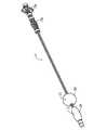
図1は、近位端14から遠位端16まで縦軸Lに沿って延びている細長い本体12を含む用具10のある典型的実施態様を示す。ある態様では、用具10の遠位端14は、管腔内の当該用具の挿入および移動を促進する円錐形を有することができる遠位の先端17を含む。さらに、または別法として、遠位の先端17は、治療区域までの送達のために、医療用具および/またはインプラントとかみ合うように構成することができる。遠位の先端17は、例えば胃腸用インプラントおよび手術用具の送達を含めて、用具10の使用目的に応じて、様々な形およびサイズを有することができることを当業者は理解するであろう。 FIG. 1 illustrates an exemplary embodiment of a
用具10は、少なくとも2個の、選択的に、また、独立して拡張可能および収縮可能な管状要素18a、18bを含むことができ、これら管状要素は、時には、本明細書で「バルーン」と称される。ある態様では、管状要素18a、18bは、本体12の遠位端14に配置され、近位に配置された制御要素20a、20bで作動されることができる。当該制御要素の操作は、下記のとおり、軸Lに沿った管状要素18a、18bの相対的移動を引き起こすことができる。さらに、制御要素20a、20bは、管状要素18a、18bの選択的拡張および収縮を容易にする。管状要素18a、18bの協調した遠位移動、ならびに放射状拡張および放射状収縮は、体内管腔の遠隔部分まで前記用具10が有効かつ好都合に進むことを可能にする。 The
管状要素18a、18bは、様々な材料から形成されることができ、当該材料は、管状である場合、管状部材の長さが減少すると、放射状に拡張でき、管状部材の長さが増加すると、放射状に収縮できる。典型的な材料は、メッシュ織(woven mesh)の形態にある生体適合性ポリマー、金属、合金を含むことができる。典型的材料は、ナイロン繊維、ニッケル-チタン形状記憶合金(「ニチノール(Nitinol)」)ワイヤー、ステンレススチールワイヤー(例、300シリーズまたは400シリーズ)およびそれらの組み合わせから形成されるメッシュ織布(woven mesh fabric)を含む。
ある態様では、管状要素18a、18bが形成される材料は、当該管状要素が管腔内壁を掴む助けになる。例えば、当該材料は、当該管状要素が管腔壁に対してその位置を保持できるように、拡張状態の当該管状要素に牽引力を提供できる。ある実施態様では、バルーンは、摩擦強化処理または表面特徴点22を含み、バルーンが管腔壁を掴む助けになることができる。管腔壁が解剖学的表面である場合、牽引面22は、好ましくは、管腔壁に裂傷を与えることなく、当該牽引面が当該壁を掴むように構成される。例えば、牽引面22は、バルーン18a、18b表面上に配置される多孔質または粗コーティングまたはオーバーレイヤーであることができる。様々な材料が把握表面(gripping surface)を提供できることを、当業者は認めるであろう。 In certain embodiments, the material from which the
別法として、牽引面22は、管状部材自体の外面によって提供されることができる。例えば、バルーン18aおよび/または18bは、図2に示されるように、メッシュ織物(woven mesh material)から形成されることができる。バルーン18a、18bの表面は、管腔壁に押し付けられると、滑らかな表面を有する従来の用具よりも良好な保持を提供できる。網織構造は、当該バルーンが管腔を裂傷を与えることなく、適切に管腔を掴むことができるように、粗および/または多孔質表面を有し、これが牽引面22を提供する。さらに、メッシュ材は、当該メッシュが拡張されると拡張し、かつ/または当該メッシュが収縮されると収縮する細孔または開口23を提供できる。管状要素が管腔内壁に押し付けられる拡張状態では、開口23は、把握を容易にすることができる。逆に、当該バルーンが収縮されると、収縮(または閉鎖)開口23は、より簡単に管腔を通過できる。 Alternatively, the
「メッシュ」という用語は、編み上げられた、織られた、および、クモの巣様の材料を含む多孔質表面を有する様々な材料を示すために使用されることを、当業者は認めるであろう。さらに、「メッシュ」は、多数の開口を有するシートから形成される材料を含むことができる。ある態様では、メッシュバルーンは、柔軟な、または、拡張可能なワイヤーから織られている。そのようなメッシュは、所望のメッシュ密度および当該メッシュが形成される材料に応じて、様々なパターンに織られることができる。例えば、当該メッシュは、本用具の縦軸Lに対して、ある角度で位置するメッシュワイヤーで、アンダー/オーバーパターンに織ることができる。当該ワイヤーは、異なる材料からできている個別のストランドで形成することができ、および/または、異なる組成のワイヤーが使用されることができる、と当業者は認めるであろう。 Those skilled in the art will appreciate that the term “mesh” is used to indicate a variety of materials having a porous surface including knitted, woven, and web-like materials. Further, a “mesh” can include a material formed from a sheet having a number of openings. In some embodiments, the mesh balloon is woven from a flexible or expandable wire. Such meshes can be woven in various patterns depending on the desired mesh density and the material from which the mesh is formed. For example, the mesh can be woven in an under / over pattern with a mesh wire positioned at an angle with respect to the longitudinal axis L of the tool. Those skilled in the art will appreciate that the wires can be formed of individual strands made of different materials and / or wires of different compositions can be used.
管状要素の構造に関係なく、当該管状要素は、好ましくは、所望の用途に従ったサイズおよび形にされる。例えば、管状要素は、その放射状収縮状態では、本体12とともに、管腔進入に使用される身体内の開口部に入って通り抜けるサイズにされる必要がある。好ましくは、身体内の開口部は、自然の開口部である。本用具は、身体開口部に入って通り抜けるサイズにされている上に、放射状の収縮状態のバルーンを含めて、本用具がトラバースを予定されている管腔最狭部に入って通り抜ける適合するサイズでもなければならない。さらに、管状要素は、本用具が通過する管腔壁の最広部に接触できるように放射状拡張状態の寸法を有する必要がある。 Regardless of the structure of the tubular element, the tubular element is preferably sized and shaped according to the desired application. For example, the tubular element, in its radially contracted state, needs to be sized with the
ある実施態様の管状要素18a、18bは、一般に、近位端30a、31aから遠位端30b、31bまで延びた細長い、または、管状の形を有する。管状要素18a、18bの放射状拡張は、近位端30a、31aと遠位端30b、31bをともに移動させることによって達成される。両端が接合されると、バルーンの長さは減少し、バルーン18a、18bの中間部33a、33bは、放射状に拡張する。逆に、近位端30a、31aと遠位端30b、31bを離すと、バルーンの長さを増加させ、それによって、当該バルーンの直径を収縮させる。 In certain embodiments, the
ある実施態様では、管状要素18a、18bの拡張および収縮は、本体部材26a、26b、28a、28bの相対的移動によって達成されることができる。図3は、本体部材26a、26b、28a、28bにかみ合わされたバルーン18a、18bを伴う用具10の遠位部分のある実施態様を示す。特に、バルーン18aは、端部30a、30bで、それぞれ、第一近位および第一遠位本体部材26a、26bにかみ合わされ、バルーン18bは、端部31a、31bで、それぞれ、第二近位および第二遠位本体部材28a、28bにかみ合わされる。近位制御要素20a、20bの作動は、互いに対して近位および遠位本体部材を移動させ、当該バルーンの長さを減少させることができ(即ち、近位本体部材26a、28aおよび遠位本体部材26b、28bを接合させることによる)、それによって、バルーンを放射状に拡張させる。逆に、バルーンの長さを増加させる当該制御要素の作動(即ち、近位本体部材26a、28aおよび遠位本体部材26b、28bを離すことによる)は、バルーン18a、18bの直径を収縮させる。制御要素20a、20bの作動は、バルーン18a、18bの収縮および拡張をコントロールする上に、本体部材26a、26b、28a、28bが、縦軸Lに沿って、独立して、互いに対してバルーン18a、18bを移動させることを可能にする。例えば、第一本体部材26a、26bおよび第二本体部材28a、28bは、互いに対して縦方向に移動されることができる。 In some embodiments, expansion and contraction of the
管状要素18a、18bは、様々な固定技術によって、本体部材26a、26b、28a、28bとかみ合わされることができる。例えば、図3に示されるように、管状要素18a、18bは、本体部材の外面32と保持バンド34の間に固定されることができる。管状要素18a、18bが、様々な他の代替または追加固定法によって本体部材26a、26b、28a、28bに固定されることができる、と当業者は認めるであろう。例えば、前記バルーンは、本体12に接着、溶接、付着および/または摩擦嵌めによってかみ合わされることができる。 The
ある実施態様では、制御要素20a、20bから本体部材26a、26b、28a、28bまで延びる作動ロッド40は、本体部材26a、26b、28a、28bを移動させ、バルーン18a、18bの選択的拡張、収縮および縦の移動をコントロールするために使用されることができる。図3に示されるある実施態様では、複数のロッドが使用される。例えば、ロッド40bは、第二遠位本体部材28bまで延びることができ、一方、ロッド40aは、第二近位本体部材28aまで延びることができる。ロッド40a、40bは、当該ロッド40a、40bの移動が本体部材の対応する移動をもたらすように、第二本体部材28a、28bとかみ合わされることができる。さらに、ロッド40a、40bは、バルーン18aに対してバルーン18bを移動させるために、ともに移動されることができる。同様に、バルーン18aに関して、本体部材26a、26bは、2個の追加ロッド(図示されず)とかみ合うことができ、バルーン18aのコントロールを可能にする。当該ロッドは、バルーン18aの放射状拡張、ならびに、18bに対するバルーン18aの相対的移動をコントロールできる。例えば、当該ロッドは、バルーン18aをバルーン18bに対して近位および遠位に移動させることができる。 In one embodiment, an actuating rod 40 extending from the
管状要素18a、18bおよび本体部材26a、26b、28a、28bの拡張および収縮がロッドに対して記述されているが、バルーンが、様々な代替法でコントロール可能であることを、当業者は認めるであろう。例えば、様々な他の機械的作動要素が使用され、各管状要素の長さ、よって、各管状要素の拡張/収縮、および独立した縦方向の移動を選択的にコントロール可能である、と当業者は認めるであろう。 Although expansion and contraction of the
ある実施態様における管状要素18a、18bと制御要素20a、20bの間の用具10の本体12は、上記のように、ロッドによって画定されることができる。別の実施態様では、本体12は、内部の管腔(図示されず)を画定する保護外殻を含み、ロッド40a、40bが、当該保護外殻に配置されることができる。外殻は、当該外殻中に各種部品を含有するように構成されることもでき、および/または、ツールおよび/または治療薬の送達用に構成されることができる。ある典型例では、本体12は、用具10の近位部分14から遠位部分16までの、インプラント、ツールおよび/または治療媒介物の送達用通路を含むことができる。 The
細長い本体12(例、ロッド40および/または外殻)は、柔軟性および/または変形性を提供する材料を含めた様々な材料から形成されることができる。特定の典型的実施態様では、細長い本体12は、金属、合金、生体適合性ポリマーまたはそれらの組み合わせから形成される。例えば、当該ロッドは、ポリマーオーバーチューブ(例、ポリエチレン、ポリプロピレンおよび/またはナイロン)に覆われた編組ステンレススチールから形成されることができる。当該ロッドは、ニチノール(Nitinol)またはバネ鋼などの固体の柔軟性材料製であることもできる。当業者は、本体12形成に使用される材料が、用具の使用目的および解剖学的特徴点周辺で操作するための用具への需要に基づいて選択されることができる、と認めるであろう。 The elongate body 12 (eg, rod 40 and / or outer shell) can be formed from a variety of materials, including materials that provide flexibility and / or deformability. In certain exemplary embodiments, the
細長い本体12の近位部分は、管状要素の拡張/収縮および/または相対的移動を制御する機構まで延びることができる。図4は、用具10の近位端の、ある実施態様の部分断面図を示し、ユーザーが近位および遠位管状要素18a、18b(図4に図示されず)の移動をコントロールできる第一および第二制御要素20a、20bを含む。各制御要素20a、20bは、管状要素18a、18bの一方をコントロールできる。 The proximal portion of the
ある態様では、制御要素20a、20bは、それぞれが、互いに対して移動し、管状要素18a、18bの直径をコントロールする近位および遠位制御部材を含む。図4に示されるように、制御要素部材48a、48b、50a、50bは、ロッド40a、40b、40cとかみ合うことができる(明確にするために、3個のロッドのみが示されている)。作動ハンドル20bは、第二近位および遠位ハンドル部材50a、50bを互いに対して移動させ、ロッド40a、40bを互いに対して移動させる。ロッド40a、40bの移動は、上記のように、バルーン18bを拡張/収縮させる。同様に、作動ハンドル20aは、第二近位および遠位制御要素部材48a、48bを互いの方に移動させ(または互いから離し)、バルーン18aの直径を拡張させる(または収縮させる)。 In certain embodiments, the
さらに、制御要素20a、20bの互いに対する移動は、管状要素18a、18bを互いに対して移動させることができる。例えば、制御要素20a、20bは、互いの方に移動し、および、互いから離れ、それによって、当該制御要素に伴うロッドを移動させることができる。当該ロッドは、バルーン18a、18bを制御要素20a、20bに連結するので、制御要素20a、20bの相対的移動は、管状要素18a、18bを互いに対して移動させる。例えば、制御要素20a、20bが互いに離れると、管状要素18a、18bを互いに対して離し、逆に、制御要素20a、20bが互いに近づくと、管状要素18a、18bを互いに近づける。 Furthermore, movement of the
図4に示されるように、制御要素20a、20bは、バルーンを拡張構造に偏らせるばね52、54を含むことができる。管状要素18a、18bが管腔内に配置され、制御要素20a、20bが作動されないと、ばね52、54は、管腔壁に対する拡張された管状要素の働きによって、管腔に対して所定の位置に用具10を保持する。ばねの力に対して制御要素20a、20bの一方または両方を強く握ると、管状要素18a、18bの一方または両方が管腔内を移動することができるように、管状要素を収縮させる。 As shown in FIG. 4, the
図5は、管状要素18a'、18b'に連結された制御要素20a'、20b'を含む用具10'の代替実施態様を示す。各制御要素20a'、20b'は、第一および第二レバーアーム70a、70b、71a、71bを含む。当該レバーアームをともにまたは別々に移動させると、ロッド40をコントロールし、よって、管状要素18a'、18b'をコントロールする。当業者は、管状要素18a、18bの使用目的および構造に応じて、用具10で様々な代替制御要素が使用されることができる、と認めるであろう。 FIG. 5 shows an alternative embodiment of the
図6〜10は、身体管腔(図示されず)内を用具10の少なくとも一部(例、遠位部分)を移動させる方法の、ある実施態様を示す。手術のための患者の準備後、本用具が患者の肛門などの身体開口部から患者の体内に挿入される。次に、図6に示されるように、近位バルーン18aが放射状に拡張し、管腔内面に接触するように、当該バルーンの長さが減少される。その後、図7に示されるように、長く伸ばされ、直径が収縮された状態の遠位バルーン18bが管腔内を遠位に移動し、その間、拡張した近位バルーン18aは、管腔壁に対して所定の位置に本用具を固定する。上記のように、バルーン18aの表面22は、本用具の滑りを防止/軽減する助けになる。図8に示されるように、いったんバルーン18bが所望の位置に移動されると、バルーン18bの長さが減少し、当該バルーンを拡張させ、管腔壁に接触させ、その位置を保持する。その後、近位バルーン18aの長さは減少し、近位バルーンを収縮させ、次に、バルーン18aは、図9および図10に示されるように、バルーン18bの方に遠位に移動し、一方、拡張したバルーン18bは管腔内に用具10を保持する。この手順が繰り返され、本用具を管腔内の所望の位置に進める。 6-10 illustrate one embodiment of a method of moving at least a portion (eg, a distal portion) of the
当業者は、各種図が、2個の管状要素18a、18bを有する用具10を説明し、図解しているが、用具10は、本用具の管腔内移動を容易にするために、任意の個数の管状要素を含むことができる、と認めるようになる。 Those skilled in the art will describe and illustrate the
特定の典型的実施態様では、用具10は、GI管の検査および/または治療に使用されることができる。用具10のサイズは、比較的小型であることが可能で、管状要素18a、18bは、直径を選択的に縮小されることが可能であるので、本用具は、標準的な内視鏡および他の管腔内用具よりも深く挿入されることができる。上部GI管に対しては、本用具は、患者の口から挿入されることができ、下部GI管に対しては、本用具は、患者の肛門から挿入されることができる。いずれにせよ、用具10は、好ましくは、本用具がGI管の管壁をかみ合わせ、GI管を移動することを可能にするサイズを有する。典型的には、GI管の最大直径は、下部GI管でほぼ30mm、上部GI管でほぼ16mmである。従って、特定の典型的実施態様では、管状要素18a、18bは、非拡張状態のほぼ16mmから拡張状態のほぼ33mmまでの範囲である直径を有することができる。当然、形とサイズは、使用目的に応じて、異なることができる。 In certain exemplary embodiments, the
当業者は、上記の実施態様に基づいて、本発明のさらなる特徴および長所を認めるであろう。従って、本発明は、添付された請求の範囲に規定される場合を除いて、特に示された、および、説明された事項に制約されるものではない。本明細書で引用された全出版物および文献は、参照することによって、そのまま本明細書に明示的に組み入れられている。 One skilled in the art will appreciate further features and advantages of the invention based on the above-described embodiments. Accordingly, the invention is not to be limited by what has been particularly shown and described, except as defined by the appended claims. All publications and references cited herein are expressly incorporated herein by reference in their entirety.
〔実施の態様〕
(1) 体内管腔をトラバースする用具において、
縦軸に沿って近位端から遠位端まで延びている細長い本体、
を含み、
前記遠位端が、第一メッシュ管状要素、および第二メッシュ管状要素を含み、
各管状要素が、第一端部、および第二端部を有し、前記管状要素はそれぞれ、選択的に、かつ独立して放射状に拡張および収縮するように構成されており、
前記管状要素が、互いに対して移動するように構成されている、
用具。
(2) 実施態様1に記載の用具において、
前記用具は、管腔内面を掴むことによって前記管腔をトラバースするように構成されている、用具。
(3) 実施態様1に記載の用具において、
前記管状要素の縦方向の移動、拡張、および収縮をコントロールするのに有効な第一制御要素、および第二制御要素、
をさらに含む、用具。
(4) 実施態様3に記載の用具において、
前記第二制御要素に対する前記第一制御要素の移動が、前記第二管状要素に対する前記第一管状要素の移動をもたらす、用具。
(5) 実施態様3に記載の用具において、
前記第一制御要素に対する前記第二制御要素の移動が、前記第一管状要素に対する前記第二管状要素の移動をもたらす、用具。
(6) 実施態様1に記載の用具において、
前記本体が、前記第一管状要素とかみ合わされた第一近位本体部材、および第一遠位本体部材、ならびに前記第二管状要素とかみ合わされた第二近位本体部材、および第二遠位本体部材を含む、用具。
(7) 実施態様6に記載の用具において、
前記第一遠位本体部材方向への前記第一近位本体部材の移動が、前記第一管状要素の放射状拡張をもたらすと同時に、前記第一管状要素の長さを減少させる、用具。
(8) 実施態様6に記載の用具において、
前記第二遠位本体部材方向への前記第二近位本体部材の移動が、前記第一管状要素の放射状拡張をもたらすと同時に、前記第一管状要素の長さを減少させる、用具。
(9) 実施態様1に記載の用具において、
前記第一管状要素、および前記第二管状要素が、メッシュ織物(woven mesh material)で作られている、用具。Embodiment
(1) In a device for traversing a body lumen,
An elongate body extending from the proximal end to the distal end along the longitudinal axis;
Including
The distal end includes a first mesh tubular element and a second mesh tubular element;
Each tubular element has a first end and a second end, each of the tubular elements being configured to selectively and independently radially expand and contract;
The tubular elements are configured to move relative to each other;
Tools.
(2) In the device according to Embodiment 1,
The device is configured to traverse the lumen by grasping an inner surface of the lumen.
(3) In the device according to Embodiment 1,
A first control element and a second control element effective to control longitudinal movement, expansion and contraction of the tubular element;
Further including a tool.
(4) In the device according to Embodiment 3,
A tool wherein movement of the first control element relative to the second control element results in movement of the first tubular element relative to the second tubular element.
(5) In the device according to embodiment 3,
A tool wherein movement of the second control element relative to the first control element results in movement of the second tubular element relative to the first tubular element.
(6) In the device according to Embodiment 1,
A first proximal body member and a first distal body member meshed with the first tubular element; and a second proximal body member and a second distal meshed with the second tubular element. A tool including a body member.
(7) In the device according to embodiment 6,
A tool, wherein movement of the first proximal body member toward the first distal body member results in radial expansion of the first tubular element while simultaneously reducing the length of the first tubular element.
(8) In the device according to Embodiment 6,
A tool, wherein movement of the second proximal body member toward the second distal body member results in a radial expansion of the first tubular element while simultaneously reducing the length of the first tubular element.
(9) In the device according to embodiment 1,
A tool wherein the first tubular element and the second tubular element are made of a woven mesh material.
(10) 身体管腔をトラバースする用具において、
細長い本体部材上に可動的に配置され、選択的に、かつ独立して縦方向の移動が可能な少なくとも2個の管状要素、
を含み、
各管状要素が、選択的にコントロール可能な長さを有し、
各管状要素が、延長された長さおよび収縮された直径を有する第一構造、ならびに縮小された長さおよび拡張された直径を有する第二構造を有する、
用具。
(11) 実施態様10に記載の用具において、
前記管状要素がメッシュ織物で形成されている、用具。
(12) 実施態様10に記載の用具において、
前記バルーンが牽引面を含む、用具。
(13) 実施態様10に記載の用具において、
前記本体の近位端に、前記第一管状要素および前記第二管状要素の縦方向の移動をコントロールするのに有効な、制御機構、
をさらに含む、用具。
(14) 実施態様13に記載の用具において、
前記本体の近位端に、前記第一構造および前記第二構造における前記第一管状要素の配置をコントロールするのに有効な、制御機構、
をさらに含む、用具。
(15) 実施態様13に記載の用具において、
前記本体の近位端に、前記第一構造および前記第二構造における前記第二管状要素の配置をコントロールするのに有効な、制御機構、
をさらに含む、用具。
(16) 実施態様14に記載の用具において、
前記制御機構が、前記第一構造および前記第二構造における前記第一管状要素の縦方向の移動および前記第一管状要素の配置をコントロールするのに有効な、第一制御要素である、用具。
(17) 実施態様15に記載の用具において、
前記制御装置が、前記第一構造および前記第二構造における前記第二管状要素の縦方向の移動および前記第二管状要素の配置をコントロールするのに有効な、第二制御要素である、用具。(10) In a device for traversing a body lumen,
At least two tubular elements movably disposed on the elongate body member and capable of selective and independent longitudinal movement;
Including
Each tubular element has a selectively controllable length;
Each tubular element has a first structure having an extended length and a contracted diameter, and a second structure having a reduced length and an expanded diameter.
Tools.
(11) In the device according to
A tool wherein the tubular element is formed of a mesh fabric.
(12) In the device according to
A tool wherein the balloon includes a pulling surface.
(13) In the device according to
A control mechanism effective to control longitudinal movement of the first tubular element and the second tubular element at a proximal end of the body;
Further including a tool.
(14) In the device according to embodiment 13,
A control mechanism effective to control the placement of the first tubular element in the first structure and the second structure at a proximal end of the body;
Further including a tool.
(15) In the device according to embodiment 13,
A control mechanism effective to control the placement of the second tubular element in the first structure and the second structure at a proximal end of the body;
Further including a tool.
(16) In the device according to
The tool, wherein the control mechanism is a first control element effective to control longitudinal movement of the first tubular element and placement of the first tubular element in the first structure and the second structure.
(17) In the device according to embodiment 15,
The tool, wherein the control device is a second control element effective to control longitudinal movement of the second tubular element and placement of the second tubular element in the first structure and the second structure.
(18) 身体の内部管腔をトラバースする方法において、
a.近位端から遠位端まで延びている細長い本体を有し、かつ遠位メッシュ管状要素および近位メッシュ管状要素を含む、管腔トラバース用具を挿入する段階と、
b.拡張された前記近位管状要素の外面が前記管腔の内面に係合(engage)するように、前記近位管状要素を放射状に拡張させる段階と、
c.前記近位管状要素に対して遠位に前記遠位管状要素を移動させる段階と、
d.拡張された前記遠位管状要素の外面が前記管腔の前記内面に係合(engage)するように、前記遠位管状要素を放射状に拡張させる段階と、
e.前記近位管状要素を放射状に収縮させ、前記遠位管状要素に向かって遠位に前記近位管状要素を移動させる段階と、
f.前記用具が前記管腔内の所望の部位に到達するまでb〜eの段階を繰り返す段階と、
を含む、方法。
(19) 実施態様18に記載の方法において、
前記用具が、手術および/または診断処置での使用に有効な医療用具を含む、方法。
(20) 実施態様18に記載の方法において、
開口(opening)が身体の自然の開口部(orifice)である、方法。
(21) 実施態様19に記載の方法において、
前記医療用具が内視鏡である、方法。(18) In a method of traversing the internal lumen of the body,
inserting a luminal traverse device having an elongated body extending from the proximal end to the distal end and comprising a distal mesh tubular element and a proximal mesh tubular element;
b. radially expanding the proximal tubular element such that the expanded outer surface of the proximal tubular element engages the inner surface of the lumen;
c. moving the distal tubular element distally relative to the proximal tubular element;
d. radially expanding the distal tubular element such that the expanded outer surface of the distal tubular element engages the inner surface of the lumen;
e. radially contracting the proximal tubular element and moving the proximal tubular element distally toward the distal tubular element;
f. repeating steps b through e until the device reaches a desired site within the lumen;
Including the method.
(19) In the method of embodiment 18,
The method wherein the device comprises a medical device effective for use in surgical and / or diagnostic procedures.
(20) In the method of embodiment 18,
The method wherein the opening is a natural orifice of the body.
(21) In the method of embodiment 19,
The method wherein the medical device is an endoscope.
Claims (10)
Translated fromJapanese縦軸に沿って近位端から遠位端まで延びている細長い本体、
を含み、
前記遠位端が、第一メッシュ管状要素、および第二メッシュ管状要素を含み、
各管状要素が、第一端部、および第二端部を有し、前記管状要素はそれぞれ、選択的に、かつ独立して放射状に拡張および収縮するように構成されており、
前記管状要素が、互いに対して移動するように構成されている、
用具。In a device for traversing the body lumen,
An elongate body extending from the proximal end to the distal end along the longitudinal axis;
Including
The distal end includes a first mesh tubular element and a second mesh tubular element;
Each tubular element has a first end and a second end, each of the tubular elements being configured to selectively and independently radially expand and contract;
The tubular elements are configured to move relative to each other;
Tools.
前記用具は、管腔内面を掴むことによって前記管腔をトラバースするように構成されている、用具。The tool according to claim 1,
The device is configured to traverse the lumen by grasping an inner surface of the lumen.
前記管状要素の縦方向の移動、拡張、および収縮をコントロールするのに有効な第一制御要素、および第二制御要素、
をさらに含む、用具。The tool according to claim 1,
A first control element and a second control element effective to control longitudinal movement, expansion and contraction of the tubular element;
Further including a tool.
前記第二制御要素に対する前記第一制御要素の移動が、前記第二管状要素に対する前記第一管状要素の移動をもたらす、用具。The tool according to claim 3,
A tool wherein movement of the first control element relative to the second control element results in movement of the first tubular element relative to the second tubular element.
前記第一制御要素に対する前記第二制御要素の移動が、前記第一管状要素に対する前記第二管状要素の移動をもたらす、用具。The tool according to claim 3,
A tool wherein movement of the second control element relative to the first control element results in movement of the second tubular element relative to the first tubular element.
前記本体が、前記第一管状要素とかみ合わされた第一近位本体部材、および第一遠位本体部材、ならびに前記第二管状要素とかみ合わされた第二近位本体部材、および第二遠位本体部材を含む、用具。The tool according to claim 1, wherein
A first proximal body member and a first distal body member meshed with the first tubular element; and a second proximal body member and a second distal meshed with the second tubular element. A tool including a body member.
前記第一遠位本体部材方向への前記第一近位本体部材の移動が、前記第一管状要素の放射状拡張をもたらすと同時に、前記第一管状要素の長さを減少させる、用具。The tool according to claim 6,
A tool, wherein movement of the first proximal body member toward the first distal body member results in radial expansion of the first tubular element while simultaneously reducing the length of the first tubular element.
前記第二遠位本体部材方向への前記第二近位本体部材の移動が、前記第一管状要素の放射状拡張をもたらすと同時に、前記第一管状要素の長さを減少させる、用具。The tool according to claim 6,
A tool, wherein movement of the second proximal body member toward the second distal body member results in a radial expansion of the first tubular element while simultaneously reducing the length of the first tubular element.
前記第一管状要素、および前記第二管状要素が、メッシュ織物で作られている、用具。The tool according to claim 1, wherein
A tool wherein the first tubular element and the second tubular element are made of mesh fabric.
細長い本体部材上に可動的に配置され、選択的に、かつ独立して縦方向の移動が可能な少なくとも2個の管状要素、
を含み、
各管状要素が、選択的にコントロール可能な長さを有し、
各管状要素が、延長された長さおよび収縮された直径を有する第一構造、ならびに縮小された長さおよび拡張された直径を有する第二構造を有する、
用具。In the device for traversing the body lumen,
At least two tubular elements movably disposed on the elongate body member and capable of selective and independent longitudinal movement;
Including
Each tubular element has a selectively controllable length;
Each tubular element has a first structure having an extended length and a contracted diameter, and a second structure having a reduced length and an expanded diameter.
Tools.
Applications Claiming Priority (2)
| Application Number | Priority Date | Filing Date | Title |
|---|---|---|---|
| US11/267,463 | 2005-11-04 | ||
| US11/267,463US7798992B2 (en) | 2005-11-04 | 2005-11-04 | Lumen traversing device |
Publications (2)
| Publication Number | Publication Date |
|---|---|
| JP2007144153Atrue JP2007144153A (en) | 2007-06-14 |
| JP5089959B2 JP5089959B2 (en) | 2012-12-05 |
Family
ID=37889633
Family Applications (1)
| Application Number | Title | Priority Date | Filing Date |
|---|---|---|---|
| JP2006299340AExpired - Fee RelatedJP5089959B2 (en) | 2005-11-04 | 2006-11-02 | Lumen Traverse Tool |
Country Status (8)
| Country | Link |
|---|---|
| US (1) | US7798992B2 (en) |
| EP (1) | EP1782726B1 (en) |
| JP (1) | JP5089959B2 (en) |
| CN (1) | CN1957835B (en) |
| AU (1) | AU2006230752B2 (en) |
| BR (1) | BRPI0604528A (en) |
| CA (1) | CA2566069C (en) |
| MX (1) | MXPA06012765A (en) |
Cited By (3)
| Publication number | Priority date | Publication date | Assignee | Title |
|---|---|---|---|---|
| JP2009050695A (en)* | 2007-07-16 | 2009-03-12 | Ethicon Endo Surgery Inc | Surgical method and device with movement assistance |
| JP2010252967A (en)* | 2009-04-23 | 2010-11-11 | Kunio Kasugai | Puncture needle for endoscope |
| JP2012522592A (en)* | 2009-04-01 | 2012-09-27 | ユニバーシティ オブ フロリダ リサーチ ファンデーション インコーポレーティッド | Device for moving an endoscope forward in a pipeline |
Families Citing this family (57)
| Publication number | Priority date | Publication date | Assignee | Title |
|---|---|---|---|---|
| EP1718193B1 (en)* | 2004-02-09 | 2013-07-03 | Smart Medical Systems Ltd. | Endoscope assembly |
| JP4772446B2 (en)* | 2005-09-30 | 2011-09-14 | オリンパスメディカルシステムズ株式会社 | Endoscope insertion aid and endoscope apparatus |
| US7625392B2 (en) | 2006-02-03 | 2009-12-01 | James Coleman | Wound closure devices and methods |
| US20100114269A1 (en)* | 2006-06-28 | 2010-05-06 | Medtronic Cryocath Lp | Variable geometry balloon catheter and method |
| US9814511B2 (en) | 2006-06-28 | 2017-11-14 | Medtronic Cryocath Lp | Variable geometry cooling chamber |
| US9242073B2 (en)* | 2006-08-18 | 2016-01-26 | Boston Scientific Scimed, Inc. | Electrically actuated annelid |
| US20080091073A1 (en)* | 2006-10-16 | 2008-04-17 | Chul Hi Park | Inflatable actuation device |
| US20080275299A1 (en)* | 2007-05-01 | 2008-11-06 | Chul Hi Park | Actuation device |
| US9301761B2 (en) | 2007-10-22 | 2016-04-05 | James E. Coleman | Anastomosis devices and methods |
| US20090131752A1 (en)* | 2007-11-19 | 2009-05-21 | Chul Hi Park | Inflatable artificial muscle for elongated instrument |
| CN103961049B (en)* | 2008-03-31 | 2017-04-12 | 智能医疗系统有限公司 | Assemblies for use with an endoscope |
| US8468637B2 (en) | 2009-02-06 | 2013-06-25 | Endoclear Llc | Mechanically-actuated endotracheal tube cleaning device |
| WO2010091309A1 (en)* | 2009-02-06 | 2010-08-12 | Endoclear, Llc | Methods for cleaning endotracheal tubes |
| EP2485643B1 (en)* | 2009-10-09 | 2020-02-26 | Flip Technologies Limited | A device for facilitating monitoring the cross-section of a gastric sleeve during formation thereof |
| US10485401B2 (en) | 2009-12-15 | 2019-11-26 | Lumendi Ltd. | Method and apparatus for manipulating the side wall of a body lumen or body cavity so as to provide increased visualization of the same and/or increased access to the same, and/or for stabilizing instruments relative to the same |
| US10149601B2 (en) | 2009-12-15 | 2018-12-11 | Lumendi Ltd. | Method and apparatus for manipulating the side wall of a body lumen or body cavity so as to provide increased visualization of the same and/or increased access to the same, and/or for stabilizing instruments relative to the same |
| US11986150B2 (en) | 2009-12-15 | 2024-05-21 | Lumendi Ltd. | Method and apparatus for manipulating the side wall of a body lumen or body cavity so as to provide increased visualization of the same and/or increased access to the same, and/or for stabilizing instruments relative to the same |
| WO2011084490A1 (en)* | 2009-12-15 | 2011-07-14 | Cornell University | Method and apparatus for stabilizing, straightening, or expanding the wall of a lumen or cavity |
| US9986893B2 (en) | 2009-12-15 | 2018-06-05 | Cornell University | Method and apparatus for manipulating the side wall of a body lumen or body cavity so as to provide increased visualization of the same and/or increased access to the same, and/or for stabilizing instruments relative to the same |
| US12121209B2 (en) | 2014-02-11 | 2024-10-22 | Cornell University | Method and apparatus for providing increased visualization and manipulation of a body side wall |
| US11877722B2 (en) | 2009-12-15 | 2024-01-23 | Cornell University | Method and apparatus for manipulating the side wall of a body lumen or body cavity |
| EP2552293B1 (en) | 2010-03-29 | 2015-01-07 | Endoclear LLC | Airway cleaning and visualization |
| US9445714B2 (en) | 2010-03-29 | 2016-09-20 | Endoclear Llc | Endotracheal tube coupling adapters |
| US8752230B2 (en) | 2011-08-01 | 2014-06-17 | Misder, Llc | Device with handle actuated element |
| US8852220B2 (en)* | 2011-09-07 | 2014-10-07 | Abbott Cardiovascular Systems, Inc. | Thrombus penetrating devices, systems, and methods |
| US9247930B2 (en) | 2011-12-21 | 2016-02-02 | James E. Coleman | Devices and methods for occluding or promoting fluid flow |
| GB2507980B (en) | 2012-11-15 | 2015-06-10 | Rolls Royce Plc | Inspection arrangement |
| US10004863B2 (en) | 2012-12-04 | 2018-06-26 | Endoclear Llc | Closed suction cleaning devices, systems and methods |
| CA2897568C (en)* | 2013-01-21 | 2020-11-17 | G.I. View Ltd. | A sealing device for colonoscopy procedure |
| US8690907B1 (en) | 2013-03-15 | 2014-04-08 | Insera Therapeutics, Inc. | Vascular treatment methods |
| US8715314B1 (en) | 2013-03-15 | 2014-05-06 | Insera Therapeutics, Inc. | Vascular treatment measurement methods |
| CN105228688B (en) | 2013-03-15 | 2019-02-19 | 伊瑟拉医疗公司 | Vascular treatment devices and methods |
| US8679150B1 (en) | 2013-03-15 | 2014-03-25 | Insera Therapeutics, Inc. | Shape-set textile structure based mechanical thrombectomy methods |
| WO2015187583A1 (en) | 2014-06-03 | 2015-12-10 | Endoclear Llc | Cleaning devices, systems and methods |
| US20170290493A1 (en)* | 2014-09-29 | 2017-10-12 | Nanyang Technological University | Carrying platform for moving a device within a conduit |
| JP2018504238A (en)* | 2015-02-06 | 2018-02-15 | ラピッド メディカル リミテッド | System and method for removing intravascular obstructions |
| JP7082052B2 (en) | 2015-09-03 | 2022-06-07 | ネプチューン メディカル インク. | A device for advancing the endoscope in the small intestine |
| CN108697423A (en) | 2016-02-16 | 2018-10-23 | 伊瑟拉医疗公司 | The part flow arrangement of suction unit and anchoring |
| EP3500151A4 (en) | 2016-08-18 | 2020-03-25 | Neptune Medical Inc. | DEVICE AND METHOD FOR IMPROVED VISUALIZATION OF THE SMALL BOWEL |
| JP7379321B2 (en) | 2017-07-20 | 2023-11-14 | ネプチューン メディカル インク. | Dynamically rigid overtube |
| US10258357B1 (en) | 2017-10-16 | 2019-04-16 | Michael Bruce Horowitz | Catheter based retrieval device with proximal body having axial freedom of movement |
| US12201315B2 (en)* | 2017-10-16 | 2025-01-21 | Retriever Medical, Inc. | Clot removal methods and devices with multiple independently controllable elements |
| US12114877B2 (en)* | 2017-10-16 | 2024-10-15 | Retriever Medical, Inc. | Clot removal methods and devices with multiple independently controllable elements |
| US10736647B2 (en)* | 2017-10-30 | 2020-08-11 | Acclarent, Inc. | Dilation catheter with navigation sensor and vent passageway in tip |
| CN107837141B (en)* | 2017-12-01 | 2019-03-26 | 南京鼓楼医院 | Ear canal drug delivery device and its application method |
| US12059128B2 (en) | 2018-05-31 | 2024-08-13 | Neptune Medical Inc. | Device and method for enhanced visualization of the small intestine |
| CN112714658A (en) | 2018-07-19 | 2021-04-27 | 海王星医疗公司 | Dynamic rigidized composite medical structure |
| WO2020214221A1 (en) | 2019-04-17 | 2020-10-22 | Neptune Medical Inc. | Dynamically rigidizing composite medical structures |
| US11793392B2 (en) | 2019-04-17 | 2023-10-24 | Neptune Medical Inc. | External working channels |
| US10809160B1 (en)* | 2019-08-21 | 2020-10-20 | Bn Intellectual Properties, Inc. | Endotracheal tube sound |
| US11420022B2 (en)* | 2020-03-06 | 2022-08-23 | Stryker Corporation | Actuating elements for bending medical devices |
| CA3178444A1 (en) | 2020-03-30 | 2021-10-07 | Neptune Medical Inc. | Layered walls for rigidizing devices |
| WO2022104262A1 (en)* | 2020-11-16 | 2022-05-19 | Lumendi Ltd. | Methods and apparatus for inverting a hollow sleeve and thereafter reverting an inverted hollow sleeve |
| KR20230133374A (en) | 2021-01-29 | 2023-09-19 | 넵튠 메디컬 인코포레이티드 | Device and method for preventing inadvertent movement of a dynamic stiffening device |
| WO2022187384A1 (en)* | 2021-03-02 | 2022-09-09 | Lumendi LLC | Method and apparatus for manipulating the side wall of a body lumen or body cavity |
| KR20250003955A (en) | 2022-04-27 | 2025-01-07 | 넵튠 메디컬 인코포레이티드 | Sanitary outer covering for endoscope |
| US12330292B2 (en) | 2023-09-28 | 2025-06-17 | Neptune Medical Inc. | Telescoping robot |
Citations (7)
| Publication number | Priority date | Publication date | Assignee | Title |
|---|---|---|---|---|
| US4389208A (en)* | 1980-11-06 | 1983-06-21 | Leveen Robert F | Catheter advancer |
| JPS59181124A (en)* | 1983-03-31 | 1984-10-15 | オリンパス光学工業株式会社 | Propelling apparatus in endoscope |
| JPH05293077A (en)* | 1992-04-20 | 1993-11-09 | Olympus Optical Co Ltd | Intraluminal inserting apparatus |
| JPH078447A (en)* | 1993-06-29 | 1995-01-13 | Olympus Optical Co Ltd | Automatic inserting device for endoscope |
| JP2002052084A (en)* | 2000-08-08 | 2002-02-19 | Asahi Optical Co Ltd | Endoscope extension |
| JP2002301020A (en)* | 2001-04-09 | 2002-10-15 | Hironori Yamamoto | Medical fixed balloon |
| US20040158143A1 (en)* | 1995-10-13 | 2004-08-12 | Transvascular Inc. | Stabilized tissue penetrating catheters |
Family Cites Families (119)
| Publication number | Priority date | Publication date | Assignee | Title |
|---|---|---|---|---|
| US2004014A (en)* | 1931-08-05 | 1935-06-04 | Alfred F Sanford | Refrigerating apparatus |
| US2004013A (en)* | 1934-07-11 | 1935-06-04 | Clarence E Reed | Antifriction bearing assembly for drills |
| US2004172A (en)* | 1934-07-31 | 1935-06-11 | Everett F Niday | Starting block |
| US4176662A (en)* | 1977-06-17 | 1979-12-04 | The United States Of America As Represented By The Administrator Of The National Aeronautics And Space Administration | Apparatus for endoscopic examination |
| DE2821048C2 (en) | 1978-05-13 | 1980-07-17 | Willy Ruesch Gmbh & Co Kg, 7053 Kernen | Medical instrument |
| GB8422863D0 (en)* | 1984-09-11 | 1984-10-17 | Univ London | Sewing machine |
| US4848168A (en)* | 1987-04-13 | 1989-07-18 | Bridgestone Corporation | Traveling device moving along elongated member |
| US4838859A (en)* | 1987-05-19 | 1989-06-13 | Steve Strassmann | Steerable catheter |
| US5090259A (en)* | 1988-01-18 | 1992-02-25 | Olympus Optical Co., Ltd. | Pipe-inspecting apparatus having a self propelled unit |
| US4921484A (en)* | 1988-07-25 | 1990-05-01 | Cordis Corporation | Mesh balloon catheter device |
| US4934786A (en)* | 1989-08-07 | 1990-06-19 | Welch Allyn, Inc. | Walking borescope |
| US5144848A (en)* | 1989-11-27 | 1992-09-08 | Olympus Optical Co., Ltd. | Intra-tube traveling apparatus |
| US5197971A (en)* | 1990-03-02 | 1993-03-30 | Bonutti Peter M | Arthroscopic retractor and method of using the same |
| US5269809A (en) | 1990-07-02 | 1993-12-14 | American Cyanamid Company | Locking mechanism for use with a slotted suture anchor |
| US5041129A (en)* | 1990-07-02 | 1991-08-20 | Acufex Microsurgical, Inc. | Slotted suture anchor and method of anchoring a suture |
| US5080663A (en)* | 1990-09-26 | 1992-01-14 | Univerity College London | Sewing device |
| US5217486A (en)* | 1992-02-18 | 1993-06-08 | Mitek Surgical Products, Inc. | Suture anchor and installation tool |
| US6010515A (en)* | 1993-09-03 | 2000-01-04 | University College London | Device for use in tying knots |
| US5713910A (en)* | 1992-09-04 | 1998-02-03 | Laurus Medical Corporation | Needle guidance system for endoscopic suture device |
| US7060077B2 (en)* | 1992-09-04 | 2006-06-13 | Boston Scientific Scimed, Inc. | Suturing instruments and methods of use |
| GB9218754D0 (en) | 1992-09-04 | 1992-10-21 | Univ London | Device for use in securing a thread |
| US6048351A (en)* | 1992-09-04 | 2000-04-11 | Scimed Life Systems, Inc. | Transvaginal suturing system |
| US5662587A (en)* | 1992-09-16 | 1997-09-02 | Cedars Sinai Medical Center | Robotic endoscopy |
| US5330442A (en) | 1992-10-09 | 1994-07-19 | United States Surgical Corporation | Suture retaining clip |
| US5549630A (en) | 1993-05-14 | 1996-08-27 | Bonutti; Peter M. | Method and apparatus for anchoring a suture |
| US5398670A (en)* | 1993-08-31 | 1995-03-21 | Ethicon, Inc. | Lumen traversing device |
| WO1995011630A1 (en) | 1993-10-25 | 1995-05-04 | Children's Medical Center Corporation | Retractable suture needle with self-contained driver |
| US5437681A (en)* | 1994-01-13 | 1995-08-01 | Suturtek Inc. | Suturing instrument with thread management |
| GB9405791D0 (en)* | 1994-03-23 | 1994-05-11 | Univ London | Device for use in cutting threads |
| DE4429117A1 (en) | 1994-08-17 | 1996-02-22 | Bess Medizintechnik Gmbh | Dilatation catheter for vessel or tissue restrictions |
| US5462558A (en) | 1994-08-29 | 1995-10-31 | United States Surgical Corporation | Suture clip applier |
| US5514159A (en)* | 1994-09-13 | 1996-05-07 | United States Surgical Corporation | Guillotine suture clip |
| US5814071A (en)* | 1994-11-10 | 1998-09-29 | Innovasive Devices, Inc. | Suture anchor assembly and methods |
| US5540705A (en)* | 1995-05-19 | 1996-07-30 | Suturtek, Inc. | Suturing instrument with thread management |
| US5827304A (en)* | 1995-11-16 | 1998-10-27 | Applied Medical Resources Corporation | Intraluminal extraction catheter |
| US5860992A (en)* | 1996-01-31 | 1999-01-19 | Heartport, Inc. | Endoscopic suturing devices and methods |
| US5709693A (en)* | 1996-02-20 | 1998-01-20 | Cardiothoracic System, Inc. | Stitcher |
| IT1285533B1 (en)* | 1996-10-22 | 1998-06-08 | Scuola Superiore Di Studi Universitari E Di Perfezionamento Sant Anna | ENDOSCOPIC ROBOT |
| US6007482A (en)* | 1996-12-20 | 1999-12-28 | Madni; Asad M. | Endoscope with stretchable flexible sheath covering |
| US5868708A (en)* | 1997-05-07 | 1999-02-09 | Applied Medical Resources Corporation | Balloon catheter apparatus and method |
| US5899921A (en)* | 1997-07-25 | 1999-05-04 | Innovasive Devices, Inc. | Connector device and method for surgically joining and securing flexible tissue repair members |
| IL121752A0 (en)* | 1997-09-11 | 1998-02-22 | Gaber Benny | Stitching tool |
| US5887594A (en)* | 1997-09-22 | 1999-03-30 | Beth Israel Deaconess Medical Center Inc. | Methods and devices for gastroesophageal reflux reduction |
| WO1999016499A1 (en)* | 1997-10-01 | 1999-04-08 | Boston Scientific Corporation | Dilation systems and related methods |
| WO1999047050A2 (en)* | 1998-03-20 | 1999-09-23 | Scimed Life Systems, Inc. | Endoscopic suture systems |
| US6249076B1 (en)* | 1998-04-14 | 2001-06-19 | Massachusetts Institute Of Technology | Conducting polymer actuator |
| US6626861B1 (en) | 1998-04-22 | 2003-09-30 | Applied Medical Resources | Balloon catheter apparatus and method |
| US6036694A (en)* | 1998-08-03 | 2000-03-14 | Innovasive Devices, Inc. | Self-tensioning soft tissue fixation device and method |
| US6200329B1 (en)* | 1998-08-31 | 2001-03-13 | Smith & Nephew, Inc. | Suture collet |
| US6162171A (en)* | 1998-12-07 | 2000-12-19 | Wan Sing Ng | Robotic endoscope and an autonomous pipe robot for performing endoscopic procedures |
| US6506196B1 (en)* | 1999-06-22 | 2003-01-14 | Ndo Surgical, Inc. | Device and method for correction of a painful body defect |
| US6821285B2 (en) | 1999-06-22 | 2004-11-23 | Ndo Surgical, Inc. | Tissue reconfiguration |
| US6835200B2 (en) | 1999-06-22 | 2004-12-28 | Ndo Surgical. Inc. | Method and devices for tissue reconfiguration |
| US6494888B1 (en) | 1999-06-22 | 2002-12-17 | Ndo Surgical, Inc. | Tissue reconfiguration |
| US6663639B1 (en)* | 1999-06-22 | 2003-12-16 | Ndo Surgical, Inc. | Methods and devices for tissue reconfiguration |
| US7744613B2 (en)* | 1999-06-25 | 2010-06-29 | Usgi Medical, Inc. | Apparatus and methods for forming and securing gastrointestinal tissue folds |
| US7416554B2 (en)* | 2002-12-11 | 2008-08-26 | Usgi Medical Inc | Apparatus and methods for forming and securing gastrointestinal tissue folds |
| JP2001313389A (en) | 2000-05-01 | 2001-11-09 | Seiko Epson Corp | Semiconductor device and method of manufacturing the same |
| DE60115020T2 (en)* | 2000-05-15 | 2006-08-03 | C.R. Bard, Inc. | ENDOSCOPIC ACCESSORY DEVICE MECHANISM |
| ES2435094T3 (en)* | 2000-05-19 | 2013-12-18 | C.R. Bard, Inc. | Device and method of tissue capture and suturing |
| US6540789B1 (en)* | 2000-06-15 | 2003-04-01 | Scimed Life Systems, Inc. | Method for treating morbid obesity |
| US6572629B2 (en)* | 2000-08-17 | 2003-06-03 | Johns Hopkins University | Gastric reduction endoscopy |
| US7037324B2 (en)* | 2000-09-15 | 2006-05-02 | United States Surgical Corporation | Knotless tissue anchor |
| US6755843B2 (en)* | 2000-09-29 | 2004-06-29 | Olympus Optical Co., Ltd. | Endoscopic suturing device |
| US6719763B2 (en)* | 2000-09-29 | 2004-04-13 | Olympus Optical Co., Ltd. | Endoscopic suturing device |
| US6997931B2 (en)* | 2001-02-02 | 2006-02-14 | Lsi Solutions, Inc. | System for endoscopic suturing |
| US8313496B2 (en)* | 2001-02-02 | 2012-11-20 | Lsi Solutions, Inc. | System for endoscopic suturing |
| US6524328B2 (en)* | 2001-04-12 | 2003-02-25 | Scion International, Inc. | Suture lock, lock applicator and method therefor |
| KR100413058B1 (en)* | 2001-04-24 | 2003-12-31 | 한국과학기술연구원 | Micro Robotic Colonoscope with Motor Locomotion |
| US20050143760A1 (en)* | 2001-05-01 | 2005-06-30 | Imran Mir A. | Endoscopic gastric constriction device |
| KR100402920B1 (en)* | 2001-05-19 | 2003-10-22 | 한국과학기술연구원 | Micro robot |
| US6558400B2 (en)* | 2001-05-30 | 2003-05-06 | Satiety, Inc. | Obesity treatment tools and methods |
| EP2308391B1 (en) | 2001-06-14 | 2016-08-31 | Endoevolution, Llc | Apparatus for surgical suturing with thread management |
| BR0210509A (en)* | 2001-06-20 | 2004-06-22 | Park Medical Llc | Anastomotic device |
| US7115136B2 (en)* | 2001-06-20 | 2006-10-03 | Park Medical Llc | Anastomotic device |
| US6988986B2 (en)* | 2002-11-25 | 2006-01-24 | G. I. View | Self-propelled imaging system |
| US6764441B2 (en)* | 2001-09-17 | 2004-07-20 | Case Western Reserve University | Peristaltically self-propelled endoscopic device |
| CA2461880A1 (en)* | 2001-10-04 | 2003-04-10 | Gibbens & Borders, Llc | Apparatus and method for thread advancing |
| US7530985B2 (en)* | 2002-01-30 | 2009-05-12 | Olympus Corporation | Endoscopic suturing system |
| US7618425B2 (en)* | 2002-01-30 | 2009-11-17 | Olympus Corporation | Endoscopic suturing system |
| US6988987B2 (en) | 2002-03-18 | 2006-01-24 | Olympus Corporation | Guide tube |
| JP4351458B2 (en) | 2002-03-18 | 2009-10-28 | オリンパス株式会社 | Endoscope insertion system |
| US20030229332A1 (en) | 2002-06-11 | 2003-12-11 | Scimed Life Systems, Inc. | Adjustable double balloon catheter with a through lumen for stone management |
| US7442198B2 (en) | 2002-06-12 | 2008-10-28 | Boston Scientific Scimed, Inc. | Suturing instrument with multi-load cartridge |
| US7063671B2 (en) | 2002-06-21 | 2006-06-20 | Boston Scientific Scimed, Inc. | Electronically activated capture device |
| US6773440B2 (en)* | 2002-07-02 | 2004-08-10 | Satiety, Inc. | Method and device for use in tissue approximation and fixation |
| US6746460B2 (en)* | 2002-08-07 | 2004-06-08 | Satiety, Inc. | Intra-gastric fastening devices |
| AU2003272277A1 (en) | 2002-09-06 | 2004-03-29 | C.R. Bard, Inc. | Endoscopic accessory mounting adaptor |
| AU2003270549A1 (en) | 2002-09-09 | 2004-03-29 | Brian Kelleher | Device and method for endoluminal therapy |
| AU2003271463A1 (en)* | 2002-09-27 | 2004-04-19 | University Of Waterloo | Micro-positioning device |
| US7229428B2 (en)* | 2002-10-23 | 2007-06-12 | Satiety, Inc. | Method and device for use in endoscopic organ procedures |
| US7090690B2 (en)* | 2002-11-19 | 2006-08-15 | Arthrocare Corporation | Devices and methods for repairing soft tissue |
| US7942884B2 (en) | 2002-12-11 | 2011-05-17 | Usgi Medical, Inc. | Methods for reduction of a gastric lumen |
| US7942898B2 (en)* | 2002-12-11 | 2011-05-17 | Usgi Medical, Inc. | Delivery systems and methods for gastric reduction |
| US20040186349A1 (en)* | 2002-12-24 | 2004-09-23 | Usgi Medical Corp. | Apparatus and methods for achieving endoluminal access |
| US6908427B2 (en)* | 2002-12-30 | 2005-06-21 | PARÉ Surgical, Inc. | Flexible endoscope capsule |
| US6892608B2 (en)* | 2003-02-28 | 2005-05-17 | Chau-Tsung Chen | Turning disc intermittent rotary mechanism |
| WO2004086986A1 (en)* | 2003-03-28 | 2004-10-14 | Gibbens Group Llc | Leverage locking reversible cyclic suturing and knot-tying device |
| US7175638B2 (en) | 2003-04-16 | 2007-02-13 | Satiety, Inc. | Method and devices for modifying the function of a body organ |
| CN1822794B (en)* | 2003-05-16 | 2010-05-26 | C.R.巴德有限公司 | Single cannula, multiple needle endoscopic suturing system |
| US7044245B2 (en)* | 2003-06-17 | 2006-05-16 | Science Applications International Corporation | Toroidal propulsion and steering system |
| US20050070931A1 (en)* | 2003-08-06 | 2005-03-31 | Rhodemann Li | Method and apparatus for creating a restriction in the stomach or other anatomical structure |
| US7833176B2 (en)* | 2003-08-13 | 2010-11-16 | G. I. View Ltd. | Pressure-propelled system for body lumen |
| EP1667586A1 (en)* | 2003-09-15 | 2006-06-14 | Abbott Laboratories | Suture locking device and methods |
| US20050070935A1 (en)* | 2003-09-30 | 2005-03-31 | Ortiz Mark S. | Single lumen access deployable ring for intralumenal anastomosis |
| US7309341B2 (en)* | 2003-09-30 | 2007-12-18 | Ethicon Endo-Surgery, Inc. | Single lumen anastomosis applier for self-deploying fastener |
| US7608086B2 (en)* | 2003-09-30 | 2009-10-27 | Ethicon Endo-Surgery, Inc. | Anastomosis wire ring device |
| US7452363B2 (en)* | 2003-09-30 | 2008-11-18 | Ethicon Endo-Surgery, Inc. | Applier for fastener for single lumen access anastomosis |
| US20050075654A1 (en)* | 2003-10-06 | 2005-04-07 | Brian Kelleher | Methods and devices for soft tissue securement |
| US20050113892A1 (en)* | 2003-11-26 | 2005-05-26 | Sproul Michael E. | Surgical tool with an electroactive polymer for use in a body |
| JP3864344B2 (en)* | 2003-12-05 | 2006-12-27 | フジノン株式会社 | Endoscope insertion aid |
| US7635345B2 (en)* | 2004-01-09 | 2009-12-22 | G. I. View Ltd. | Pressure-propelled system for body lumen |
| US7635346B2 (en)* | 2004-01-09 | 2009-12-22 | G. I. View Ltd. | Pressure-propelled system for body lumen |
| EP1718193B1 (en)* | 2004-02-09 | 2013-07-03 | Smart Medical Systems Ltd. | Endoscope assembly |
| CA2556228C (en) | 2004-02-13 | 2014-05-13 | Satiety, Inc. | Methods for reducing hollow organ volume |
| MXPA06009971A (en) | 2004-02-27 | 2007-08-08 | Satiety Inc | Methods and devices for reducing hollow organ volume. |
| US20050203488A1 (en) | 2004-03-09 | 2005-09-15 | Usgi Medical Inc. | Apparatus and methods for mapping out endoluminal gastrointestinal surgery |
| JP3962999B2 (en)* | 2004-03-29 | 2007-08-22 | 有限会社エスアールジェイ | Endoscope device |
| JP3874296B2 (en)* | 2004-03-31 | 2007-01-31 | 有限会社エスアールジェイ | Balloon control device |
- 2005
- 2005-11-04USUS11/267,463patent/US7798992B2/enactiveActive
- 2006
- 2006-10-20AUAU2006230752Apatent/AU2006230752B2/ennot_activeCeased
- 2006-10-30CACA2566069Apatent/CA2566069C/ennot_activeExpired - Fee Related
- 2006-11-02JPJP2006299340Apatent/JP5089959B2/ennot_activeExpired - Fee Related
- 2006-11-03MXMXPA06012765Apatent/MXPA06012765A/enactiveIP Right Grant
- 2006-11-03CNCN2006101437514Apatent/CN1957835B/ennot_activeExpired - Fee Related
- 2006-11-03BRBRPI0604528-6Apatent/BRPI0604528A/ennot_activeApplication Discontinuation
- 2006-11-03EPEP06255676.6Apatent/EP1782726B1/ennot_activeNot-in-force
Patent Citations (7)
| Publication number | Priority date | Publication date | Assignee | Title |
|---|---|---|---|---|
| US4389208A (en)* | 1980-11-06 | 1983-06-21 | Leveen Robert F | Catheter advancer |
| JPS59181124A (en)* | 1983-03-31 | 1984-10-15 | オリンパス光学工業株式会社 | Propelling apparatus in endoscope |
| JPH05293077A (en)* | 1992-04-20 | 1993-11-09 | Olympus Optical Co Ltd | Intraluminal inserting apparatus |
| JPH078447A (en)* | 1993-06-29 | 1995-01-13 | Olympus Optical Co Ltd | Automatic inserting device for endoscope |
| US20040158143A1 (en)* | 1995-10-13 | 2004-08-12 | Transvascular Inc. | Stabilized tissue penetrating catheters |
| JP2002052084A (en)* | 2000-08-08 | 2002-02-19 | Asahi Optical Co Ltd | Endoscope extension |
| JP2002301020A (en)* | 2001-04-09 | 2002-10-15 | Hironori Yamamoto | Medical fixed balloon |
Cited By (3)
| Publication number | Priority date | Publication date | Assignee | Title |
|---|---|---|---|---|
| JP2009050695A (en)* | 2007-07-16 | 2009-03-12 | Ethicon Endo Surgery Inc | Surgical method and device with movement assistance |
| JP2012522592A (en)* | 2009-04-01 | 2012-09-27 | ユニバーシティ オブ フロリダ リサーチ ファンデーション インコーポレーティッド | Device for moving an endoscope forward in a pipeline |
| JP2010252967A (en)* | 2009-04-23 | 2010-11-11 | Kunio Kasugai | Puncture needle for endoscope |
Also Published As
| Publication number | Publication date |
|---|---|
| CA2566069A1 (en) | 2007-05-04 |
| EP1782726A2 (en) | 2007-05-09 |
| EP1782726A3 (en) | 2008-02-27 |
| JP5089959B2 (en) | 2012-12-05 |
| CN1957835A (en) | 2007-05-09 |
| AU2006230752B2 (en) | 2013-09-19 |
| US20070106302A1 (en) | 2007-05-10 |
| EP1782726B1 (en) | 2016-01-20 |
| AU2006230752A1 (en) | 2007-05-24 |
| CA2566069C (en) | 2014-07-29 |
| US7798992B2 (en) | 2010-09-21 |
| BRPI0604528A (en) | 2007-08-28 |
| CN1957835B (en) | 2012-02-01 |
| MXPA06012765A (en) | 2007-05-03 |
Similar Documents
| Publication | Publication Date | Title |
|---|---|---|
| JP5089959B2 (en) | Lumen Traverse Tool | |
| JP6181235B2 (en) | Medical device for treating foreign matter | |
| ES2792100T3 (en) | Clot retention mechanical thrombectomy appliances | |
| CN109982661B (en) | Compression of the heart valve annulus and installation of the valve annulus onto the heart valve annulus | |
| JP5173930B2 (en) | Surgical device | |
| US7559934B2 (en) | Beaded basket retrieval device | |
| CN110267627B (en) | Systems, devices and methods for accurate deployment of implants in the prostatic urethra | |
| JP4550591B2 (en) | Positioning tool and method for implanting a medical device | |
| US9592066B2 (en) | Selectively bendable remote gripping tool | |
| ES2387911T3 (en) | Tied spiral for the treatment of body lumens | |
| US20090012356A1 (en) | Endoscopic delivery devices and methods | |
| JP2023027100A (en) | Method and apparatus for stent delivery | |
| US20060020254A1 (en) | Suction assisted tissue plication device and method of use | |
| JP2004512133A (en) | Medical gripping device | |
| US20130211415A1 (en) | Steerable tissue manipulation medical devices and related methods of use | |
| JP2009279412A (en) | Shape lockable apparatus and method for advancing instrument through unsupported anatomy | |
| JP5186659B2 (en) | Medical gripping device | |
| JP2001513008A (en) | Dynamic stent | |
| WO2006014640A1 (en) | Device to aid in stone removal and laser lithotripsy | |
| JP2011529733A (en) | A body lumen or a side wall of the body cavity is straightened and flattened and / or an instrument is placed in the body lumen or body cavity so as to provide a three-dimensional exposure of the body lumen or body lesion or abnormality. Method and apparatus for stabilization against | |
| KR20190133719A (en) | Apparatus and method for tissue retraction | |
| US9833347B2 (en) | Apparatuses for manipulating medical devices and related methods for use | |
| JP2023545058A (en) | Systems, devices, and methods for retrieval of implants within the prostatic urethra | |
| KR20230058497A (en) | Grappling systems and methods for lumen apposition or wound defects | |
| JP6899482B2 (en) | Universal recovery device for removing obstacles from the body cavity |
Legal Events
| Date | Code | Title | Description |
|---|---|---|---|
| RD04 | Notification of resignation of power of attorney | Free format text:JAPANESE INTERMEDIATE CODE: A7424 Effective date:20071130 | |
| RD04 | Notification of resignation of power of attorney | Free format text:JAPANESE INTERMEDIATE CODE: A7424 Effective date:20081017 | |
| A621 | Written request for application examination | Free format text:JAPANESE INTERMEDIATE CODE: A621 Effective date:20091102 | |
| A977 | Report on retrieval | Free format text:JAPANESE INTERMEDIATE CODE: A971007 Effective date:20111024 | |
| A131 | Notification of reasons for refusal | Free format text:JAPANESE INTERMEDIATE CODE: A131 Effective date:20111101 | |
| A601 | Written request for extension of time | Free format text:JAPANESE INTERMEDIATE CODE: A601 Effective date:20120201 | |
| A602 | Written permission of extension of time | Free format text:JAPANESE INTERMEDIATE CODE: A602 Effective date:20120206 | |
| A521 | Written amendment | Free format text:JAPANESE INTERMEDIATE CODE: A523 Effective date:20120224 | |
| A131 | Notification of reasons for refusal | Free format text:JAPANESE INTERMEDIATE CODE: A131 Effective date:20120327 | |
| A601 | Written request for extension of time | Free format text:JAPANESE INTERMEDIATE CODE: A601 Effective date:20120627 | |
| A602 | Written permission of extension of time | Free format text:JAPANESE INTERMEDIATE CODE: A602 Effective date:20120702 | |
| A521 | Written amendment | Free format text:JAPANESE INTERMEDIATE CODE: A523 Effective date:20120719 | |
| TRDD | Decision of grant or rejection written | ||
| A01 | Written decision to grant a patent or to grant a registration (utility model) | Free format text:JAPANESE INTERMEDIATE CODE: A01 Effective date:20120814 | |
| A01 | Written decision to grant a patent or to grant a registration (utility model) | Free format text:JAPANESE INTERMEDIATE CODE: A01 | |
| A61 | First payment of annual fees (during grant procedure) | Free format text:JAPANESE INTERMEDIATE CODE: A61 Effective date:20120912 | |
| FPAY | Renewal fee payment (event date is renewal date of database) | Free format text:PAYMENT UNTIL: 20150921 Year of fee payment:3 | |
| R150 | Certificate of patent or registration of utility model | Ref document number:5089959 Country of ref document:JP Free format text:JAPANESE INTERMEDIATE CODE: R150 Free format text:JAPANESE INTERMEDIATE CODE: R150 | |
| R250 | Receipt of annual fees | Free format text:JAPANESE INTERMEDIATE CODE: R250 | |
| R250 | Receipt of annual fees | Free format text:JAPANESE INTERMEDIATE CODE: R250 | |
| R250 | Receipt of annual fees | Free format text:JAPANESE INTERMEDIATE CODE: R250 | |
| R250 | Receipt of annual fees | Free format text:JAPANESE INTERMEDIATE CODE: R250 | |
| R250 | Receipt of annual fees | Free format text:JAPANESE INTERMEDIATE CODE: R250 | |
| LAPS | Cancellation because of no payment of annual fees |