JP2007143129A - Input device for inputting password and mobile phone provided with the same input device - Google Patents
Input device for inputting password and mobile phone provided with the same input deviceDownload PDFInfo
- Publication number
- JP2007143129A JP2007143129AJP2006286454AJP2006286454AJP2007143129AJP 2007143129 AJP2007143129 AJP 2007143129AJP 2006286454 AJP2006286454 AJP 2006286454AJP 2006286454 AJP2006286454 AJP 2006286454AJP 2007143129 AJP2007143129 AJP 2007143129A
- Authority
- JP
- Japan
- Prior art keywords
- detection sensor
- specific function
- shape
- execution
- input
- Prior art date
- Legal status (The legal status is an assumption and is not a legal conclusion. Google has not performed a legal analysis and makes no representation as to the accuracy of the status listed.)
- Pending
Links
Images


Landscapes
- Telephone Set Structure (AREA)
- Mobile Radio Communication Systems (AREA)
- Telephone Function (AREA)
Abstract
Description
Translated fromJapanese本発明は、暗証番号等を入力する為の入力装置及びその入力装置を備えた携帯電話装置、特に操作部の表面に接触検知センサが設けられた携帯電話装置に関する。 The present invention relates to an input device for inputting a personal identification number and the like and a mobile phone device including the input device, and more particularly to a mobile phone device provided with a contact detection sensor on the surface of an operation unit.
銀行等に置いているATM等は、通常カード挿入後暗証番号を入力することにより現金が引き出される。しかしながら、暗証番号を入力する際に、横或いは後ろから見ることにより容易に暗証番号が他人に知られてしまう。
このようなことを回避する為にさまざまな技術が提案されており、例えば特開2000−99801号公報(特許文献1)には、テンキーの各数字キーの位置をランダムに変更する技術が開示されている。
Various techniques have been proposed in order to avoid such a problem. For example, Japanese Patent Laid-Open No. 2000-99801 (Patent Document 1) discloses a technique for randomly changing the position of each numeric key of a numeric keypad. ing.
しかしながら、このような技術を用いたとしても、ユーザが暗証番号を入力する際に、他人がパネルに表示されている数字を見ることにより、どの数字が押されたかを知ることができる。
携帯電話のキーロック機能を解除する際にも同様に、他人がキーロック番号の押下操作を盗み見ることによりキーロック番号を知ることが可能である。However, even if such a technique is used, when a user inputs a personal identification number, it is possible to know which number has been pressed by seeing the number displayed on the panel by another person.
Similarly, when releasing the key lock function of the mobile phone, it is possible for another person to know the key lock number by seeing the operation of pressing the key lock number.
本願発明は、このような課題を解決する為のものであり、請求項1記載の入力装置は、接触感知センサと、該接触感知センサ上をなぞられた形を記憶する記憶手段と、特定の機能の実行を禁止する禁止手段と、前記禁止手段が特定の機能の実行を禁止している状態で、前記記憶手段に記憶されている形と同一の形が前記接触感知センサから入力されたと判定すると、前記特定の機能の実行を許可するよう制御する制御手段と、を有することを特徴とする。The invention of the present application is to solve such a problem, and the input device according to
請求項2記載の入力装置は、接触感知センサと、該接触感知センサ上でなぞられた形に基づいて該当する数字を判定する数字判定手段と、数字を記憶する記憶手段と、特定の機能の実行を禁止する禁止手段と、前記禁止手段が特定の機能の実行を禁止している状態で、前記接触感知センサ上でなぞられた形に基づいて前記数字判定手段が数字を判定し、該判定された数字と同一の数字が前記記憶手段に記憶されている場合に、前記特定機能の実行禁止を解除するよう制御する制御手段と、を有することを特徴とする。 The input device according to
請求項3記載の入力装置は、接触感知センサと、該接触感知センサ上でなぞられた形に基づいて該当する文字を判定する文字判定手段と、文字を記憶する記憶手段と、特定の機能の実行を禁止する禁止手段と、前記禁止手段が特定の機能の実行を禁止している状態で、前記接触感知センサ上でなぞられた形に基づいて前記文字判定手段が文字を判定し、該判定された文字と同一の文字が前記記憶手段に記憶されている場合に、前記特定機能の実行禁止を解除するよう制御する制御手段と、を有することを特徴とする。
請求項4記載の入力装置は、接触感知センサと、該接触感知センサ上でなぞられた形に基づいて該当する記号を判定する記号判定手段と、記号を記憶する記憶手段と、特定の機能の実行を禁止する禁止手段と、前記禁止手段が特定の機能の実行を禁止している状態で、前記接触感知センサ上でなぞられた形に基づいて前記記号判定手段が記号を判定し、該判定された記号と同一の記号が前記記憶手段に記憶されている場合に、前記特定機能の実行禁止を解除するよう制御する制御手段と、を有することを特徴とする。
請求項5記載の携帯電話装置は、接触感知センサと、該接触感知センサ上をなぞられた形を記憶する記憶手段と、特定の機能の実行を禁止する禁止手段と、前記禁止手段が特定の機能の実行を禁止している状態で、前記記憶手段に記憶されている形と同一の形が前記接触感知センサから入力されたと判定すると、前記特定の機能の実行を許可するよう制御する制御手段と、を有する入力装置を備えている。
請求項6記載の携帯電話装置は、接触感知センサと、該接触感知センサ上をなぞられた形を記憶する記憶手段と、キー操作を禁止するキー操作禁止手段と、前記キー操作禁止手段がキー操作を禁止している状態で、前記記憶手段に記憶されている形と同一の形が前記接触感知センサから入力されたと判定すると、前記キー操作を許可するよう制御する制御手段と、を有する入力装置を備えたことを特徴とする。The input device according to
The input device according to claim 4 is a touch detection sensor, a symbol determination unit that determines a corresponding symbol based on a shape traced on the touch detection sensor, a storage unit that stores the symbol, and a specific function. Prohibiting means for prohibiting execution, and in a state where the prohibiting means prohibits execution of a specific function, the symbol determining means determines a symbol based on the shape traced on the touch sensor, and the determination Control means for controlling to release the prohibition of execution of the specific function when the same symbol as the generated symbol is stored in the storage means.
The cellular phone device according to
The cellular phone device according to
本発明によれば、ユーザが接触感知センサ上をなぞることにより、特定機能の実行禁止を解除する為、他人に容易に暗証番号を知られることを回避することが可能である。According to the present invention, since the prohibition of the execution of the specific function is canceled by tracing the contact detection sensor by the user, it is possible to avoid that the secret number is easily known to others.
次に、本発明の一実施形態に係る携帯電話装置について、図面を参照して説明する。
図1は本実施例装置である携帯電話装置の斜視図である。本実施例装置は、テンキー48といった通常のキー操作部以外に、ユーザが指で触れることにより操作可能な接触検知センサ56も搭載している、又、前記接触検知センサ56は、テンキー48及びテンキー48の周囲の領域に配置されている。
図2は、本実施例の使用形態を示す斜視図である。ユーザは、テンキー48及びその周辺に配置されている接触検知センサ56(図2の点線で囲っている部分)を指でなぞることにより、入力操作を行うことが可能である。
図3に示すように、携帯電話装置10は、アンテナ16と接続された通信部12を備えている。この通信部12は、後述のベースバンド部14からの信号をアンテナ16を介して基地局へ発信し、あるいはアンテナ16を介して基地局からの電波を受信する。
また、通信部12は、ベースバンド部14と接続されている。ベースバンド部14は、CDMA処理回路18と、音声コーデック20と、を有している。ここで、CDMA処理回路18は、符号分割多元接続、スクランブル、誤り制御、タイミング検出を行う。また、音声コーデック20は、音声を圧縮(符号化)、伸張(復号化)したり、アナログとデジタルの変換を行ったり、内部の増幅回路(図示省略)により受話音量やマイクロホンの感度を変更する。
また、ベースバンド部14には、切替回路22が接続されている。この切替回路22には、増幅回路24を介して第1スピーカ26が接続されている。この第1スピーカ26は、増幅回路24で増幅されたベースバンド部14の電気信号を音声に変換する。この第1スピーカ26は、ユーザの耳にあてて通話に使用される。
また、切替回路22には、増幅回路28を介してマイクロホン30が接続されている。このマイクロホン30は、通話に使用され、音声を電気信号に変換する。マイクロホン30により出力された電気信号は、増幅回路28で増幅されてベースバンド部14に出力される。
また、切替回路22には、増幅回路32を介して第2スピーカ34が接続されている。
この第2スピーカ34は、増幅回路32で増幅されたベースバンド部14の電気信号を音声に変換する。この第2スピーカ34は、受話音を周囲の人にも聞かせるための拡声用のスピーカである。また、第2スピーカ34は、着信報知の鳴動も行う。なお、これらの3つの増幅回路24、28、32は、ゲインを固定しており、第1スピーカ26及び第2スピーカ34の音量やマイクロホン30の感度を変更することはできないようになっている。
この切替回路22は、ベースバンド部14との接続を、第1スピーカ26用の増幅回路24とマイクロホン30用の増幅回路28側にするか、あるいは拡声用の第2スピーカ34用の増幅回路32とマイクロホン30用の増幅回路28側にするかを切り替える。Next, a mobile phone device according to an embodiment of the present invention will be described with reference to the drawings.
FIG. 1 is a perspective view of a mobile phone device which is the device of this embodiment. The apparatus of this embodiment is equipped with a
FIG. 2 is a perspective view showing a usage pattern of this embodiment. The user can perform an input operation by tracing the
As shown in FIG. 3, the
The
In addition, a switching circuit 22 is connected to the
Further, the
Further, a second speaker 34 is connected to the switching circuit 22 via an
The second speaker 34 converts the electric signal of the
The switching circuit 22 is connected to the
また、通信部12、ベースバンド部14、切替回路22には、制御回路(制御部)36がそれぞれ接続されている。この制御回路36の制御により上述した切替回路22による切り替えが行われる。また、制御回路36によりベースバンド部14の音声コーデック20が制御され、音声コーデック20により第1スピーカ26及び第2スピーカ34の音量やマイクロホン30の感度が変更される。制御回路36には、ROM38が接続されており、ROM38に格納されているシステムプログラムに基づき各部を制御する。 A control circuit (control unit) 36 is connected to each of the
また、制御回路36には、入力部44が接続されている。この入力部44は、電話番号等の入力を行うテンキー48と、通話の開始を操作する通話キー50と、通話の終了を操作する切キー52と、OKキー54と、クリアキー55と、を有している。
ここで、テンキー48には、1〜9の各入力ボタンと、♯ボタンと、*ボタン(本実施形態では12個のボタンとなる)とが含まれる。また、図4に示すように全てのテンキー48の表面と、テンキー48周辺の筐体表面には、ユーザが接触したことを検知する接触検知センサ56が設けられている。この接触検知センサ56は、従来から知られているものであり、例えば、透明電極等が用いられている。この接触検知センサ56は、回路基板58に形成された配線パターンと電気的に接続されており(図示せず)、更に、回路基板58は制御回路36と電気的に接続されている。この為、ユーザが接触検知センサ56に触れたことを示す信号は、接触検知センサ56、回路基板58、を介して制御回路36へ入力される。
尚、本実施例装置では、接触検知センサ56を筐体表面に配置しているが、筐体及びキー48の裏面側のように筐体内部に配置しても良い。例えば、静電容量検知型の接触検知センサであれば、筐体内部に配置することが可能である。
また、制御回路36には、所定の色のLED素子を備えた照明部46が接続されている。照明部46のLED素子の発光により、ディスプレイ(表示部)42が所定の色に施される。
RAM40には、暗証番号データが4桁格納される。
制御回路36内部には接触検知センサ56から入力された暗証番号を一時的に格納する第1バッファ71と第2バッファ72とを有している。詳細な動作説明については後ほど説明する。
本実施例装置はこのような構成である。次に、図3に示す構成の携帯電話装置の実施例の動作について以下に説明する。
本実施例では、ユーザが接触検知センサ56を用いて4桁の暗証番号を入力することにより、キーロックをオン(又はオフ)操作可能としている。例えば、図5は接触検知センサ56の使用形態を示す図であるが、図5に示すように、ユーザが接触検知センサ56上をなぞることにより、暗証番号(例えば、1234)の入力が行われる。
次に暗証番号の登録を行う際の動作について説明する。図6は、暗証番号の登録を行う際の動作を示すフロー図である。
図6のS1ステップでは、制御回路36は、入力部44から暗証番号の登録動作を開始するよう指示があると判定すると、S2ステップへ処理を進める。
S2ステップでは、制御回路36は、情報の初期化を行う。例えば、制御回路36内部に搭載されている第1バッファ71をクリアし、S3ステップへ処理を進める。
S3ステップでは、制御回路36は、入力部44の操作があると判定するとS6ステップへ処理を進め、接触検知センサ56から入力操作があると判定するとS4ステップへ処理を進める。An
Here, the
In the present embodiment, the
The
The
The
The apparatus of this embodiment has such a configuration. Next, the operation of the embodiment of the cellular phone device configured as shown in FIG. 3 will be described below.
In the present embodiment, the key lock can be turned on (or off) when the user inputs a four-digit password using the
Next, an operation when registering a personal identification number will be described. FIG. 6 is a flowchart showing an operation when registering a personal identification number.
In step S1 of FIG. 6, when the
In step S2, the
In step S3, when it is determined that there is an operation of the
S4ステップでは、ユーザが接触検知センサ56上をなぞった形状(例えば、線や数字の形状)を制御回路36の第1バッファ71に一時的に格納する。具体的には、制御回路36は、回路基板58を介して接触検知センサ56から入力した信号に基づいて、例えば図5の(a)に示すような「1」の数字がなぞられたらと判定すると、「1」の文字の形状のデータを制御回路36の第1バッファ71に格納する
続くS5ステップでは、制御回路36は、上記S4ステップで格納した形状(例えば番号)をディスプレイ42に表示させ、続いてユーザのキー操作により1桁の形状の登録が完了し、S3ステップへ処理を戻す。In step S <b> 4, the shape traced on the
このように、S3〜S5ステップを繰り返す度に、図5(a)〜(d)に示すように、1桁ずつ形状のデータ(例えば、、線や数字の形状)が入力されると共に1桁ずつディスプレイ42に切換え表示される、更に入力された形状のデータ(線や数字の形状)は第1バッファ71に格納される。この為、S3〜S5ステップが4回繰り返されると、第1バッファ71には4つの形状のデータ(例えば4桁の暗証番号)が格納されることとなる。
S6ステップでは、制御回路36は、前記S3ステップで入力されたキーがクリアキー55であると判定するとS2ステップへ処理を戻し、そうでなければS7ステップへ処理を進める。
S7ステップでは、制御回路36は、前記S3ステップで入力されたキーがOKキー54であると判定するとS8ステップへ処理を進め、クリアキー55とOKキー54以外のキーであると判定すると、そのキーの入力を無効にし、S3ステップへ処理を戻す。
尚、S3、S6〜S7ステップにおいて、テンキーを検出する構成を取り入れても良い。In this way, each time the steps S3 to S5 are repeated, as shown in FIGS. 5A to 5D, shape data (for example, the shape of a line or a number) is input one digit at a time. Further, the input shape data (line and number shapes) which are switched and displayed on the display 42 are stored in the
In step S6, if the
In step S7, if the
It should be noted that a configuration for detecting a numeric keypad may be adopted in steps S3 and S6 to S7.
以上説明したように、S1ステップ〜S7ステップを繰り返すことにより(ユーザが4回接触検知センサ56上をなぞることにより)、4桁の形状のデータ(例えば、線や数字の形状)が第1バッファ71に一時的に格納される。
S8ステップでは、制御回路36は、情報の初期化を行う。例えば、制御回路36内部に搭載されている第2バッファ72をクリアし、S9ステップへ処理を進める。
S9ステップでは、制御回路36は、入力部44の操作があると判定するとS12ステップへ処理を進め、接触検知センサ56から入力操作があると判定するとS10ステップへ処理を進める。As described above, when the steps S1 to S7 are repeated (by the user tracing the
In step S8, the
In step S9, when it is determined that there is an operation of the
S10ステップでは、ユーザが接触検知センサ56上をなぞった形状のデータを制御回路36の第2バッファ72に一時的に格納し、S1〜S7ステップで第1バッファ72に格納した形状のデータと照合する。具体的には、制御回路36は、回路基板58を介して接触検知センサ56から入力した信号に基づいて、例えば図5の(a)に示すような「1」の文字がなぞられたらと判定すると、「1」の文字の形状のデータを制御回路36の第2バッファ72に格納し、第1バッファ71に格納している形状のデータと照合する。
続くS11ステップでは、制御回路36は、上記S10ステップで照合した結果のデータを第2バッファ72に格納させ、S9ステップへ処理を進める。In step S10, the shape data traced on the
In the subsequent step S11, the
このように、S9〜S11ステップでは、例えば図5(a)〜(d)に示すように、1桁ずつ暗証番号が入力されると、1桁ずつ第1バッファ71に格納されている形状のデータと照合される(S3〜S5ステップで入力された形状のデータと照合される)又、その照合結果は第2バッファ72に格納される。
S12ステップでは、制御回路36は、前記S9ステップで入力されたキーがクリアキー55であると判定するとS8ステップへ処理を戻し、そうでなければS13ステップへ処理を進める。
S13ステップでは、制御回路36は、前記S9ステップで入力されたキーがOKキー54であると判定するとS14ステップへ処理を進め、クリアキー55とOKキー54以外のキーであると判定するとこれらのキーの押下を無効にし、S9ステップへ処理を戻す。
S14ステップでは、制御回路36は、第2バッファ72に格納されている照合結果(S9〜S11ステップで格納された照合結果)の4桁が全て一致すると判定したものであると判定すると、4桁の暗証番号をROM38に格納し暗証番号の登録を完了させ、一方、1桁でも不一致があると判定すると、ディスプレイ42にエラー表示させ、登録失敗として処理を終了する。Thus, in steps S9 to S11, for example, as shown in FIGS. 5 (a) to 5 (d), when a password is input one digit at a time, it is stored in the
In step S12, if it is determined that the key input in step S9 is the
In step S13, if the
In step S14, if the
このように、本実施例の暗証番号の登録動作では、S1〜S7ステップにおいて、ユーザが接触検知センサ56上をなぞることにより4桁の形状が入力されると、その形状のデータが第1バッファ71に一時的に格納される。続いて、S8〜S15ステップにおいて、ユーザが再度接触検知センサ56上をなぞることにより4桁の形状が入力されると、その形状のデータが第2バッファ72に一時的に格納され、第1バッファ71に格納された形状のデータと第2バッファ72に格納された形状のデータが照合される。照合の結果4桁全てが一致すると、第1バッファ72(又は第2バッファ72)に格納されている形状のデータが記憶手段である書換可能なROM38に格納され、登録が完了する。このように2度同じ形状(例えば暗証番号)を入力することにより、一度入力された暗証番号が正確に文字認識されるか否かを確認できる。仮に、2度同じ暗証番号を入力して同一の番号であると認識されなかった場合には、その暗証番号は携帯電話装置が認識し難い数字(例えば、5と6等)である為、ユーザは他の認識しやすい番号を暗証番号として登録することができる。
ここで第1バッファ71に記憶された登録時の形状と、第2バッファ72に記憶された入力時の形状との照合は、例えば次のように行うことができる。
すなわち、まずユーザが指で「2」という文字をなぞると、指には幅があるので、接触検知センサ56は細い線の接触を検出するのではなく、ある程度幅(指の幅)を持った線の接触を検出する。そこで、この指幅の中心に線が描かれたと判定する、即ち、描かれた線は図7Aに示すM1(L1)であると判定する。しかし、この線を登録すると、再度全く同じ軌跡でユーザが線を描くのは困難である。この為、線にある程度のマージン領域(図7AのA1)を持たせている。このマージン領域は、ユーザの指の幅の約10〜20%ぐらいの幅を持っており、図7Bに示すようにこのマージン領域(A1)にユーザの指幅の中心(M2(L2))が入るようにユーザが線を描くと、同じ文字が入力されたと判定するようになっている。As described above, in the password registration operation of the present embodiment, when a 4-digit shape is input by the user tracing on the
Here, the registration shape stored in the
That is, when the user first traces the character “2” with his / her finger, the finger has a width, so the
又、ユーザが、登録された形状と相似な形状(例えば、図7Aの「2」の数字を拡大又は縮小した「2」)を入力した場合でも、一致する形状が入力されたと判定するようにすることができる。例えば、拡大された数字の「2」が入力された場合には、登録された線(図7AのM1)とマージン領域(図7AのA1)を拡大し、入力した数字(ユーザの指幅の中心で描かれた数字)との一致を見ることにより、一致する形状が入力されたかを判定することができる。一方、縮小された数字の「2」が入力された場合には、登録された線(図7AのM1)とマージン領域(図7AのA1)を縮小し、入力した数字(ユーザの指幅の中心で描かれた数字)との一致を見ることにより、一致する形状が入力されたかを判定することができる。 Further, even when the user inputs a shape similar to the registered shape (for example, “2” obtained by enlarging or reducing the number “2” in FIG. 7A), it is determined that a matching shape has been input. can do. For example, when the enlarged number “2” is input, the registered line (M1 in FIG. 7A) and the margin area (A1 in FIG. 7A) are expanded, and the input number (of the user's finger width) is expanded. By looking at the coincidence with the number drawn at the center, it is possible to determine whether or not a coincident shape has been input. On the other hand, when the reduced number “2” is input, the registered line (M1 in FIG. 7A) and the margin area (A1 in FIG. 7A) are reduced, and the input number (of the user's finger width) is reduced. By looking at the coincidence with the number drawn at the center, it is possible to determine whether or not a coincident shape has been input.
また、登録時の形状は指でなぞった形状、即ち指の幅ほどある線そのものを第1バッファ71に記憶してもよいし、指でなぞった形状の頂点を結んだ外形形状を第1バッファに記憶してもよい。この場合、入力時の形状も同様に入力された形状の頂点を結んだ外形形状を第2バッファに記憶して一致度を判定する。この場合も外形形状の相似度を判定して一致度を判定する方法を採ることができる。
第1バッファ71に記憶された登録時の形状と、第2バッファ72に記憶された入力時の形状との照合方法はこれに限らず、他の周知の文字認識方法を採用しても良い。例えば、特開平09−34998号公報に記載されているように、入力された線の2値パターンを得て、この2値パターンを太め処理にて太めることにより、入力された形状の特徴を抽出する方法や、特開2000−76381号公報に記載されているように、筆記ストロークの始点と終点を仮想線分で連結し、入力された文字が何であるかを認識する方法等がある。In addition, the shape at the time of registration may be stored in the
The collation method between the registered shape stored in the
次に、装置をキーロック状態にした後の暗証番号の入力動作について以下に説明する。 Next, an operation for inputting a personal identification number after setting the apparatus in the key lock state will be described below.
図8は、キーロック解除を行うための形状のデータ(例えば番号)を入力する際の動作を示すフロー図である。 FIG. 8 is a flowchart showing an operation when inputting shape data (for example, a number) for releasing the key lock.
図8のS51ステップでは、制御回路36は、入力部44からキーロック解除のための暗証番号入力動作を開始するよう指示があると判定すると、S52ステップへ処理を進める。 In step S51 of FIG. 8, when the
S52ステップでは、制御回路36は、情報の初期化を行う。例えば、制御回路36内部に搭載されている第1バッファ71をクリアし、S53ステップへ処理を進める。 In step S52, the
S53ステップでは、制御回路36は、入力部44の操作があると判定するとS56ステップへ処理を進め、接触検知センサ56から入力操作があると判定するとS54ステップへ処理を進める。
S54ステップでは、ユーザが接触検知センサ56上をなぞった形状のデータ(例えば番号)を制御回路36の第1バッファ71に一時的に格納する。具体的には、制御回路36は、回路基板58を介して接触検知センサ56から入力した信号に基づいて、例えば図5の(a)に示すような1の文字がなぞられたらと判定すると、1の文字の形状データを制御回路36の第1バッファ71に格納すると共に、格納した形状のデータとROM38に格納されている形状のデータとを比較して一致するか否かを判定する(照合する)。
キーロック解除の際に入力された形状とROM38に記憶された形状との一致判定は先に述べた登録時に第1バッファ71に記憶された登録時の形状と、第2バッファ72に記憶された入力時の形状との照合方法と同様にすることができる。In step S53, if it is determined that there is an operation of the
In step S <b> 54, data (for example, a number) in a shape traced on the
The coincidence determination between the shape input when the key lock is released and the shape stored in the
続くS55ステップでは、制御回路36は、上記S54ステップで判定した照合結果を第1バッファ71に格納し、S53ステップへ処理を戻す。 In the subsequent step S55, the
S56ステップでは、制御回路36は、S53ステップで入力されたキーが、クリアキー55であると判定するとS52ステップへ処理を戻し、そうでなければS57ステップへ処理を進める。 In step S56, if the
S57ステップでは、制御回路36は、S53ステップで入力されたキーが、OKキー54であると判定するとS58ステップへ処理を進め、それ以外のキーであると判定すると押下されたキーの押下を無効にし、S53ステップへ処理を戻す。 In step S57, if the
S58ステップでは、制御回路36は、第1バッファ71に格納されている照合結果(S53〜S55ステップで格納された照合結果)の4桁が全て一致すると判定したものであると判定すると、暗証番号が一致したと判定し、キーロックを解除し処理を終了する。一方、照合結果が1桁でも一致しないと判定すると、S59ステップでエラー通知をし、処理を終了する。 In step S58, if the
このように、本実施例では、ユーザが接触検知センサ56上をなぞることにより、暗証番号を入力することができる。この為、従来のテンキー操作により暗証番号を入力する方法に比べ、簡単に暗証番号を入力することができ、特にテンキー操作に不慣れなユーザにとって利便性の高いものである。又、他人に暗証番号の入力操作を見られたとしても、テンキーに比べ暗証番号の入力操作が複雑である為、他人が容易に正規の暗証番号を知ることができない。 Thus, in the present embodiment, the user can input the personal identification number by tracing over the
尚、本実施例では、接触検知センサ56が検出したなぞられた形状を記憶する構成としたが、接触検知センサ56が検出したなぞられた形状を、近似する文字や数字や記号等のデータに変換し、文字や数字や記号等のデータとして記憶する構成としても良い。このような構成とした場合、暗証番号が接触検知センサ56により入力されると、入力された形状を番号等のデータに変換し、予めされた格納されている番号と一致するか否かを判定し、一致すればキーロックを解除する、といった構成とすることができる。 In this embodiment, the traced shape detected by the
又、上記本実施例では、接触検知センサ56を用いて入力するものは、番号に限定していたが、テンキー操作による入力であれ、接触検知センサ56による入力であれ、暗証番号の入力によりキーロックを解除する構成である場合には、例えば、ユーザが4桁の暗証番号として、自分の生年月日や車のナンバーや連続する番号を登録する場合が多々あり、容易にキーロックを解除されてしまう可能性がある。 Further, in the present embodiment, what is input using the
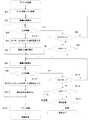
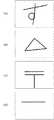
このような問題を解決するために、例えば、暗証番号の代わりに、図9に示すような文字「す」、記号「三角」、図形「郵便マーク」、線「横棒」、或いは点等を登録する構成としても良い。このような構成とすることにより、入力すべき情報がより複雑になり、他人に簡単にキーロックを解除されるといったことを回避することが可能である。 In order to solve such a problem, for example, instead of a personal identification number, a character “s”, a symbol “triangle”, a figure “post mark”, a line “horizontal bar”, or a dot as shown in FIG. It is good also as a structure to register. By adopting such a configuration, it is possible to avoid that the information to be input becomes more complicated and the key lock is easily released by another person.
更に、本実施例では形状が一致すればキーロックを解除する構成としているが、入力した形状とROM38に記憶した形状が完全に一致しなくても、先に述べたようにある程度近似あるいは相似すれば正規な暗証番号が入力されたと判定する構成としても良い。又、入力された形状の大きさやパネルの位置が異なっていても、正規な暗証番号が入力されたと判定する構成としても良い。又、液晶表示部に接触検知を検出するセンサを設けてもよい。
尚、本実施例では携帯電話装置で実施したが、銀行のATM(AUTOMATIC TELLER MACHINE)や、PDA(PERSONAL DIGITAL ASSISTANCE)等でも同様に実施可能である。Further, in this embodiment, the key lock is released when the shapes match. However, even if the input shape and the shape stored in the
In the present embodiment, the present invention is implemented by a mobile phone device, but it can also be implemented in the same manner by a bank ATM (AUTOMATIC TELLER MACHINE), a PDA (PERSONAL DIGITAL ASSISTANCE), or the like.
10 携帯電話装置
36 制御回路
40 ROM
44 入力部
48 テンキー
56 接触検知センサ
71 第1バッファ
72 第2バッファ10
44
Claims (6)
Translated fromJapanese前記禁止手段が特定の機能の実行を禁止している状態で、前記記憶手段に記憶されている形と同一の形が前記接触感知センサから入力されたと判定すると、前記特定の機能の実行を許可するよう制御する制御手段と、を有することを特徴とする入力装置。A touch detection sensor, a storage means for storing a shape traced on the touch detection sensor, a prohibition means for prohibiting execution of a specific function,
When it is determined that the same form as that stored in the storage means is input from the touch sensor while the prohibition means prohibits execution of the specific function, execution of the specific function is permitted. And an input device characterized by having control means for controlling the operation.
前記禁止手段が特定の機能の実行を禁止している状態で、前記接触感知センサ上でなぞられた形に基づいて前記数字判定手段が数字を判定し、該判定された数字と同一の数字が前記記憶手段に記憶されている場合に、前記特定機能の実行禁止を解除するよう制御する制御手段と、を有することを特徴とする入力装置。A contact detection sensor, a number determination unit that determines a corresponding number based on the shape traced on the contact detection sensor, a storage unit that stores a number, and a prohibition unit that prohibits execution of a specific function;
In a state where the prohibiting unit prohibits execution of a specific function, the number determining unit determines a number based on the shape traced on the touch sensor, and the same number as the determined number is An input device comprising: control means for controlling to release the prohibition of execution of the specific function when stored in the storage means.
前記禁止手段が特定の機能の実行を禁止している状態で、前記接触感知センサ上でなぞられた形に基づいて前記文字判定手段が文字を判定し、該判定された文字と同一の文字が前記記憶手段に記憶されている場合に、前記特定機能の実行禁止を解除するよう制御する制御手段と、を有することを特徴とする入力装置。A contact detection sensor, a character determination unit that determines a corresponding character based on a shape traced on the contact detection sensor, a storage unit that stores a character, a prohibition unit that prohibits execution of a specific function,
In a state where the prohibiting unit prohibits execution of a specific function, the character determining unit determines a character based on the shape traced on the touch sensor, and a character identical to the determined character is found. An input device comprising: control means for controlling to release the prohibition of execution of the specific function when stored in the storage means.
前記禁止手段が特定の機能の実行を禁止している状態で、前記接触感知センサ上でなぞられた形に基づいて前記記号判定手段が記号を判定し、該判定された記号と同一の記号が前記記憶手段に記憶されている場合に、前記特定機能の実行禁止を解除するよう制御する制御手段と、を有することを特徴とする入力装置。A contact detection sensor, a symbol determination unit that determines a corresponding symbol based on a shape traced on the contact detection sensor, a storage unit that stores the symbol, and a prohibition unit that prohibits execution of a specific function;
In a state where the prohibiting unit prohibits execution of a specific function, the symbol determining unit determines a symbol based on the shape traced on the touch sensor, and the same symbol as the determined symbol is determined. An input device comprising: control means for controlling to release the prohibition of execution of the specific function when stored in the storage means.
前記禁止手段が特定の機能の実行を禁止している状態で、前記記憶手段に記憶されている形と同一の形が前記接触感知センサから入力されたと判定すると、前記特定の機能の実行を許可するよう制御する制御手段と、を有する入力装置を備えたことを特徴とする携帯電話装置。A touch detection sensor, a storage means for storing a shape traced on the touch detection sensor, a prohibition means for prohibiting execution of a specific function,
When it is determined that the same form as that stored in the storage means is input from the touch sensor while the prohibition means prohibits execution of the specific function, execution of the specific function is permitted. And a control means for controlling the mobile phone device.
前記キー操作禁止手段がキー操作を禁止している状態で、前記記憶手段に記憶されている形と同一の形が前記接触感知センサから入力されたと判定すると、前記キー操作を許可するよう制御する制御手段と、を有する入力装置を備えたことを特徴とする携帯電話装置。A touch detection sensor, storage means for storing a shape traced on the touch detection sensor, key operation prohibiting means for prohibiting key operation,
When it is determined that the same shape as that stored in the storage means is input from the touch sensor in a state where the key operation prohibiting means prohibits the key operation, the key operation is controlled to be permitted. And an input device having a control means.
Priority Applications (1)
| Application Number | Priority Date | Filing Date | Title |
|---|---|---|---|
| JP2006286454AJP2007143129A (en) | 2005-10-21 | 2006-10-20 | Input device for inputting password and mobile phone provided with the same input device |
Applications Claiming Priority (2)
| Application Number | Priority Date | Filing Date | Title |
|---|---|---|---|
| JP2005306785 | 2005-10-21 | ||
| JP2006286454AJP2007143129A (en) | 2005-10-21 | 2006-10-20 | Input device for inputting password and mobile phone provided with the same input device |
Publications (1)
| Publication Number | Publication Date |
|---|---|
| JP2007143129Atrue JP2007143129A (en) | 2007-06-07 |
Family
ID=38205369
Family Applications (1)
| Application Number | Title | Priority Date | Filing Date |
|---|---|---|---|
| JP2006286454APendingJP2007143129A (en) | 2005-10-21 | 2006-10-20 | Input device for inputting password and mobile phone provided with the same input device |
Country Status (1)
| Country | Link |
|---|---|
| JP (1) | JP2007143129A (en) |
- 2006
- 2006-10-20JPJP2006286454Apatent/JP2007143129A/enactivePending
Similar Documents
| Publication | Publication Date | Title |
|---|---|---|
| CN101292213B (en) | Input device for inputting password etc. and mobile phone device provided with the input device | |
| US9521142B2 (en) | System and method for generating passwords using key inputs and contextual inputs | |
| US20160140379A1 (en) | Improvements in or relating to user authentication | |
| JP2002159052A (en) | Mobile terminal with finger print authentication function | |
| KR100674441B1 (en) | Character input device and method using fingerprint recognition in portable wireless terminal | |
| US20040203411A1 (en) | Mobile communications device | |
| KR20080097397A (en) | Input device for inputting password, etc. and mobile phone device equipped with the input device | |
| JP2008124525A (en) | Unit for inputting personal identification number and portable telephone therewith | |
| JP2007228562A (en) | Input device for inputting password and portable telephone device having the input device | |
| JP3969262B2 (en) | Mobile terminal device | |
| CN100524198C (en) | Method and apparatus for secure data entry using multi-function keys | |
| JP2008078763A (en) | Mobile phone | |
| JP2015208025A (en) | Input device and portable telephone | |
| JP2007241487A (en) | Device for confirming secret code number or the like | |
| JP2007143129A (en) | Input device for inputting password and mobile phone provided with the same input device | |
| JP2007228561A (en) | Input device for inputting password and portable telephone device having the input device | |
| JP2006277522A (en) | Information processor and method for authenticating information processor | |
| JP2006155261A (en) | Mobile device | |
| US20210209599A1 (en) | Device and method for secure identification of a user | |
| KR100556884B1 (en) | Braille Recognition Device and Method of Mobile Communication Terminal | |
| JP2007109128A (en) | Input device for inputting password or the like, and cellular phone device having input device | |
| WO2016016997A1 (en) | Mobile information terminal, method for controlling mobile information terminal, and communication system | |
| KR100625950B1 (en) | Braille input device and method | |
| JP2005242706A (en) | User authentication and collation apparatus | |
| KR20210155298A (en) | Multi finger scan based user interface |
Legal Events
| Date | Code | Title | Description |
|---|---|---|---|
| A977 | Report on retrieval | Free format text:JAPANESE INTERMEDIATE CODE: A971007 Effective date:20080206 | |
| A131 | Notification of reasons for refusal | Free format text:JAPANESE INTERMEDIATE CODE: A131 Effective date:20080219 | |
| A521 | Written amendment | Free format text:JAPANESE INTERMEDIATE CODE: A523 Effective date:20080410 | |
| A02 | Decision of refusal | Free format text:JAPANESE INTERMEDIATE CODE: A02 Effective date:20081021 | |
| A521 | Written amendment | Free format text:JAPANESE INTERMEDIATE CODE: A523 Effective date:20081027 | |
| A911 | Transfer of reconsideration by examiner before appeal (zenchi) | Free format text:JAPANESE INTERMEDIATE CODE: A911 Effective date:20081205 | |
| A912 | Removal of reconsideration by examiner before appeal (zenchi) | Free format text:JAPANESE INTERMEDIATE CODE: A912 Effective date:20090109 |