JP2007141555A - Fuel cell - Google Patents
Fuel cellDownload PDFInfo
- Publication number
- JP2007141555A JP2007141555AJP2005331319AJP2005331319AJP2007141555AJP 2007141555 AJP2007141555 AJP 2007141555AJP 2005331319 AJP2005331319 AJP 2005331319AJP 2005331319 AJP2005331319 AJP 2005331319AJP 2007141555 AJP2007141555 AJP 2007141555A
- Authority
- JP
- Japan
- Prior art keywords
- gas diffusion
- fuel cell
- diffusion layer
- fuel
- separator plate
- Prior art date
- Legal status (The legal status is an assumption and is not a legal conclusion. Google has not performed a legal analysis and makes no representation as to the accuracy of the status listed.)
- Pending
Links
Images


Classifications
- Y—GENERAL TAGGING OF NEW TECHNOLOGICAL DEVELOPMENTS; GENERAL TAGGING OF CROSS-SECTIONAL TECHNOLOGIES SPANNING OVER SEVERAL SECTIONS OF THE IPC; TECHNICAL SUBJECTS COVERED BY FORMER USPC CROSS-REFERENCE ART COLLECTIONS [XRACs] AND DIGESTS
- Y02—TECHNOLOGIES OR APPLICATIONS FOR MITIGATION OR ADAPTATION AGAINST CLIMATE CHANGE
- Y02E—REDUCTION OF GREENHOUSE GAS [GHG] EMISSIONS, RELATED TO ENERGY GENERATION, TRANSMISSION OR DISTRIBUTION
- Y02E60/00—Enabling technologies; Technologies with a potential or indirect contribution to GHG emissions mitigation
- Y02E60/30—Hydrogen technology
- Y02E60/50—Fuel cells
Landscapes
- Fuel Cell (AREA)
Abstract
Translated fromJapaneseDescription
Translated fromJapanese本発明は、固体高分子型燃料電池に関し、特にセパレータ板のランド部下の温度をセパレータ板のチャネル部下の温度と同等になるようにしてランド部下の触媒層を有効に活用できる燃料電池に関するものである。 The present invention relates to a polymer electrolyte fuel cell, and more particularly to a fuel cell that can effectively utilize a catalyst layer under a land portion so that the temperature under the land portion of the separator plate is equal to the temperature under the channel portion of the separator plate. is there.
固体高分子型燃料電池は、固体高分子膜から成る電解質層を一対の電極で挟んだ構造を有し、一対の電極のうちの燃料極(アノード)に水素を含有する燃料ガスを供給すると共に、一対の電極のうちの空気極(カソード)に酸素を含有する酸化ガスを供給し、各電極の電解質層側の面で下記式の電気化学反応を生じさせて、電極から電気エネルギーを取り出す。 The polymer electrolyte fuel cell has a structure in which an electrolyte layer made of a polymer electrolyte membrane is sandwiched between a pair of electrodes, and supplies a fuel gas containing hydrogen to a fuel electrode (anode) of the pair of electrodes. Then, an oxidizing gas containing oxygen is supplied to the air electrode (cathode) of the pair of electrodes, and an electrochemical reaction of the following formula is caused on the surface of each electrode on the electrolyte layer side to extract electric energy from the electrodes.
燃料極反応:H2 → 2H+ + 2e−…(1)
空気極反応:2H+ + 2e− + (1/2)O2 → H2O …(2)Fuel electrode reaction: H2 → 2H+ + 2e− (1)
Air electrode reaction: 2H+ + 2e− + (1/2) O2 → H2 O (2)
燃料極に対する燃料ガスの供給方法としては、水素貯蔵装置から純水素である燃料ガスを直接供給する方法や、水素を含有する燃料を改質してこれを燃料ガスとして供給する方法が知られている。
この水素貯蔵装置としては、高圧ガスタンク、液化水素タンク及び水素吸蔵合金タンク等があり、水素を含有する燃料としては、天然ガス、メタノール及びガソリン等がある。他方、空気極に供給する酸化ガスとしては、一般的に空気が利用されている。As a method of supplying fuel gas to the fuel electrode, a method of directly supplying a fuel gas that is pure hydrogen from a hydrogen storage device, or a method of reforming a fuel containing hydrogen and supplying it as a fuel gas is known. Yes.
Examples of the hydrogen storage device include a high-pressure gas tank, a liquefied hydrogen tank, a hydrogen storage alloy tank, and the like, and examples of the hydrogen-containing fuel include natural gas, methanol, and gasoline. On the other hand, air is generally used as the oxidizing gas supplied to the air electrode.
固体高分子型燃料電池では、電解質層を保湿状態にしておく必要があり、電解質層の性能を充分に引き出して発電効率を向上させるためには、電解質層の水分量を最適に保つ必要がある。このため、固体高分子型燃料電池では、燃料極に導入する燃料ガス及び空気極に導入する空気に対して、予め充分な加湿を行っている。 In the polymer electrolyte fuel cell, the electrolyte layer needs to be kept moisturized, and in order to fully draw out the performance of the electrolyte layer and improve the power generation efficiency, it is necessary to keep the water content of the electrolyte layer optimal. . For this reason, in the polymer electrolyte fuel cell, sufficient humidification is performed in advance on the fuel gas introduced into the fuel electrode and the air introduced into the air electrode.
ところで、固体高分子型燃料電池では、上述した電気化学反応の進行に伴って空気極側で水が生じる。この生成水は、空気極に供給している酸化ガス中に気化し、酸化ガスとともに燃料電池外に排出されるのである。しかし、生成量が多いときやガス流路中に部分的に温度が低い領域があると、空気極を構成するガス拡散層内で水蒸気が凝縮して同ガス拡散層内に水が滞留してしまうことがある。 By the way, in the polymer electrolyte fuel cell, water is generated on the air electrode side as the above-described electrochemical reaction proceeds. This generated water is vaporized in the oxidizing gas supplied to the air electrode and is discharged out of the fuel cell together with the oxidizing gas. However, when the amount of production is large or there is a region where the temperature is partially low in the gas flow path, water vapor is condensed in the gas diffusion layer constituting the air electrode and water is retained in the gas diffusion layer. May end up.
燃料極側では、電気化学反応による生成水は存在しないが、先述の如く導入する燃料ガスに予め加湿を行っているので、燃料ガスの消費とともにガス量が減少すると、燃料ガス中の水蒸気が燃料極を構成するガス拡散層内で凝縮して同ガス拡散層内に水が滞留してしまうことがある。 On the fuel electrode side, water produced by the electrochemical reaction does not exist, but since the fuel gas to be introduced is previously humidified as described above, when the amount of gas decreases as the fuel gas is consumed, the water vapor in the fuel gas is converted into fuel. Water may accumulate in the gas diffusion layer due to condensation in the gas diffusion layer constituting the electrode.
上記のようにガス拡散層内に水が滞留すると、ガス拡散層の空孔が水で塞がれて燃料ガスの拡散や空気の拡散が阻害される、いわゆるフラッディング現象(水つまり)が生じ、燃料電池の発電出力性能が低下することがあった。 When water stays in the gas diffusion layer as described above, the so-called flooding phenomenon (water clogging) occurs in which the pores of the gas diffusion layer are blocked with water and the fuel gas diffusion and the air diffusion are inhibited, The power output performance of the fuel cell may be reduced.
従来の燃料電池のセルの構造では、空気極のガス拡散層の厚さが燃料極のガス拡散層の厚さよりも薄く設定されることによって空気極での発熱を有効に抑えることにより、使用中の燃料電池の出力の低下を防ぐことが提案されている。この空気極のガス拡散層にはセパレータ板が配置されており、セパレータ板のランド部間には、酸化ガスが通るチャネル部が形成されている(例えば、特許文献1参照)。
ところが、上記した従来の燃料電池の構造の空気極のガス拡散層では、空気極側のセパレータ板のランド部の温度が、セパレータ板のチャネル部の温度よりも低く、ランド部に接するガス拡散層の部分には、液水が形成されて滞留し易い。この液水の滞留の影響により、ランド部に接するガス拡散層下の触媒層が有効に活用されない。このように触媒層が有効に活用されないと、ランド部下の触媒層に酸素が供給されずに、高電流密度条件におけるフラッディングを抑制することができないという問題点があった。 However, in the gas diffusion layer of the air electrode of the conventional fuel cell structure described above, the temperature of the land portion of the separator plate on the air electrode side is lower than the temperature of the channel portion of the separator plate, and the gas diffusion layer in contact with the land portion In this portion, liquid water is easily formed and stays. Due to the influence of the liquid water retention, the catalyst layer under the gas diffusion layer in contact with the land portion is not effectively utilized. If the catalyst layer is not effectively utilized in this way, there is a problem that oxygen is not supplied to the catalyst layer below the land portion and flooding under high current density conditions cannot be suppressed.
本発明は、上記従来の課題に着目して成されたものであって、セパレータ板のランド部下の温度をセパレータ板のチャネル部下の温度と同等になるようにして、ランド部下の触媒層を有効に活用してフラッディングを抑制することができる燃料電池を提供することを目的としている。 The present invention has been made paying attention to the above-mentioned conventional problems, and the catalyst layer under the land portion is made effective by making the temperature under the land portion of the separator plate equal to the temperature under the channel portion of the separator plate. It is an object of the present invention to provide a fuel cell that can be used for suppressing flooding.
本発明者は、上記目的を達成すべく鋭意検討した結果、セパレータ板のランド部とガス拡散層の間に、導電性を有しセパレータ板の熱伝導率よりも小さな熱伝導率を有する部位が配置されることにより、上記目的を達成できることを見出し、本発明を完成するに至った。 As a result of intensive studies to achieve the above object, the present inventor has a portion between the land portion of the separator plate and the gas diffusion layer that has conductivity and a thermal conductivity smaller than the thermal conductivity of the separator plate. As a result of the arrangement, the inventors have found that the above object can be achieved, and have completed the present invention.
即ち、本発明の燃料電池は、固体高分子膜から成る電解質膜と、上記電解質膜の一方の面に配置された燃料極と、上記電解質膜の他方の面に配置された空気極を有し、上記燃料極と上記空気極は、それぞれ触媒層とガス拡散層を有し、各上記ガス拡散層には、ランド部を有するセパレータ板が配置されている燃料電池であって、上記セパレータ板の上記ランド部と上記ガス拡散層の間には、導電性を有し上記セパレータ板の熱伝導率よりも小さな熱伝導率を有する部位が配置されていることを特徴とする。 That is, the fuel cell of the present invention has an electrolyte membrane made of a solid polymer membrane, a fuel electrode disposed on one surface of the electrolyte membrane, and an air electrode disposed on the other surface of the electrolyte membrane. The fuel electrode and the air electrode each have a catalyst layer and a gas diffusion layer, and each gas diffusion layer is a fuel cell in which a separator plate having a land portion is disposed. Between the land portion and the gas diffusion layer, a portion having conductivity and a thermal conductivity smaller than the thermal conductivity of the separator plate is disposed.
本発明の燃料電池は、好ましくは上記部位は、多孔体で形成されている。この場合には、
多孔体の空隙(空気)の低熱伝導特性を積極的に用いることができ、多孔体の部位を配置することで、セパレータ板のみの構造に比較して、必然的に熱抵抗は増加する。In the fuel cell of the present invention, preferably, the portion is formed of a porous body. In this case,
The low thermal conductivity characteristics of the voids (air) of the porous body can be positively used, and the arrangement of the porous body portion inevitably increases the thermal resistance compared to the structure of the separator plate alone.
本発明の燃料電池は、好ましくは上記部位は、上記セパレータ板の上記ランド部に表面処理を施すことで多孔体が一体的に形成されている。この場合には、ランド部に対して、あらかじめ用意した付加部位を後工程で付加する場合に比べて、部品点数の削減が可能である。 In the fuel cell according to the present invention, the porous body is preferably integrally formed in the portion by subjecting the land portion of the separator plate to surface treatment. In this case, the number of parts can be reduced compared to the case where an additional site prepared in advance is added to the land portion in a subsequent process.
本発明の燃料電池は、好ましくは上記多孔体には撥水処理が施されている。この場合には、チャネル部内の液水やガス拡散層の表面の液水、又はランド部下のガス拡散層に堆積した液水が、付加した部位に侵入するのを抑制することができる。 In the fuel cell of the present invention, the porous body is preferably subjected to water repellent treatment. In this case, the liquid water in the channel part, the liquid water on the surface of the gas diffusion layer, or the liquid water deposited on the gas diffusion layer below the land part can be prevented from entering the added part.
本発明の燃料電池は、好ましくは上記多孔体の気孔径は、上記ガス拡散層の気孔径と比較して小さく設定されている。この場合には、液水が付加した部位に侵入するのをさらに抑制することができる。 In the fuel cell of the present invention, the pore size of the porous body is preferably set smaller than the pore size of the gas diffusion layer. In this case, it is possible to further inhibit the liquid water from entering the added site.
本発明の燃料電池は、好ましくは上記多孔体は、上記ランド部と上記ランド部の間のチャネル部の内壁に沿って形成されており、上記ランド部における上記多孔体の上記ガス拡散層に接する第1部分の厚みが、上記チャネル部の内壁に沿って形成された上記多孔体の第2部分の厚みに比べて、大きく設定されている。この場合には、仮にチャネル部内に液水が多く存在してたとしても、チャネル部の内壁の全周囲にわたって設けた付加した部位の存在により、付加した部位を経由して空気極側では酸素拡散、燃料極側ではプロトンの拡散が可能であり、所定電圧の維持と向上が図れる。 In the fuel cell of the present invention, preferably, the porous body is formed along an inner wall of a channel portion between the land portion and the land portion, and is in contact with the gas diffusion layer of the porous body in the land portion. The thickness of the first portion is set larger than the thickness of the second portion of the porous body formed along the inner wall of the channel portion. In this case, even if a large amount of liquid water is present in the channel part, oxygen diffusion occurs on the air electrode side via the added part due to the presence of the added part provided all around the inner wall of the channel part. On the fuel electrode side, protons can be diffused, and a predetermined voltage can be maintained and improved.
本発明によれば、セパレータ板のランド部とガス拡散層の間には、導電性を有しセパレータ板の熱伝導率よりも小さな熱伝導率を有する部位が配置されることにより、セパレータ板のランド部下の温度をセパレータ板のチャネル部下の温度と同等になるようにして、ランド部下の触媒層を有効に活用してフラッディングを抑制することができる。 According to the present invention, between the land portion of the separator plate and the gas diffusion layer, a portion having conductivity and a thermal conductivity smaller than the thermal conductivity of the separator plate is disposed. Flooding can be suppressed by effectively utilizing the catalyst layer under the land so that the temperature under the land becomes equal to the temperature under the channel of the separator plate.
以下、本発明を実施例により更に詳細に説明するが、本発明は以下の実施例に限定されるものではない。 EXAMPLES Hereinafter, although an Example demonstrates this invention still in detail, this invention is not limited to a following example.
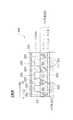
図1は、本発明の燃料電池の好ましい実施形態を示している。図2は、図1の燃料電池1の断面構造例を示している。
図1の燃料電池1は、固体高分子型燃料電池であり、セル2とセパレータ板3,4から構成されている。セル2は、固体高分子型燃料電池を構成する発電要素である。図1と図2に示す燃料電池1は、任意に複数個スタックすることで、スタック構造体を構成することができる。FIG. 1 shows a preferred embodiment of the fuel cell of the present invention. FIG. 2 shows an example of a cross-sectional structure of the fuel cell 1 of FIG.
The fuel cell 1 of FIG. 1 is a polymer electrolyte fuel cell, and is composed of a cell 2 and separator plates 3 and 4. The cell 2 is a power generation element that constitutes a solid polymer fuel cell. The fuel cell 1 shown in FIG. 1 and FIG. 2 can constitute a stack structure by arbitrarily stacking a plurality of fuel cells.
セル2は、平板状の単位セルあるいはセル板とも呼ぶことができ、固体高分子の電解質膜5と、燃料極6と、空気極7により構成されている。
燃料極6は、触媒層10とガス拡散層11を積層することで構成されている。空気極7は、触媒層12とガス拡散層13を積層することで構成されている。燃料極6側の触媒層10と、空気極7側の触媒層12との間には、電解質膜5が挟まれている。The cell 2 can also be called a flat unit cell or cell plate, and is composed of a solid polymer electrolyte membrane 5, a fuel electrode 6, and an air electrode 7.
The fuel electrode 6 is configured by laminating a catalyst layer 10 and a gas diffusion layer 11. The air electrode 7 is configured by laminating a catalyst layer 12 and a gas diffusion layer 13. An electrolyte membrane 5 is sandwiched between the catalyst layer 10 on the fuel electrode 6 side and the catalyst layer 12 on the air electrode 7 side.
電解質膜5は、湿潤状態において良好なイオン伝導性を示し、燃料極6と空気極7の間でプロトンを移動させるイオン交換膜として機能する。
燃料極6の触媒層10と空気極7の触媒層12は、電解質膜5の一方の面側と他方の面側にそれぞれ配置されている。The electrolyte membrane 5 exhibits good ion conductivity in a wet state, and functions as an ion exchange membrane that moves protons between the fuel electrode 6 and the air electrode 7.
The catalyst layer 10 of the fuel electrode 6 and the catalyst layer 12 of the air electrode 7 are respectively disposed on one surface side and the other surface side of the electrolyte membrane 5.
燃料極6のガス拡散層11は、供給される水素ガス、プロトンを触媒層10に供給する機能を有し、
空気極7のガス拡散層13は、供給される空気を触媒層12に供給する機能を有する。ガス拡散層11は、発電反応により生じる電荷を外部回路に移動させ、ガス拡散層13は、水等を外部に放出する。ガス拡散層11,13は、電子伝導性を有する多孔体で作られており、例えばカーボンペーパで作られている。The gas diffusion layer 11 of the fuel electrode 6 has a function of supplying supplied hydrogen gas and protons to the catalyst layer 10.
The gas diffusion layer 13 of the air electrode 7 has a function of supplying supplied air to the catalyst layer 12. The gas diffusion layer 11 moves charges generated by the power generation reaction to an external circuit, and the gas diffusion layer 13 releases water or the like to the outside. The gas diffusion layers 11 and 13 are made of a porous body having electronic conductivity, and are made of, for example, carbon paper.
ガス拡散層11,13は、図2に示すように、マイクロポーラス層15とサブストレート16を有している。マイクロポーラス層15は触媒層10,12側にそれぞれ配置され、サブストレート16はセパレータ板3,4側にそれぞれ配置されている。 The gas diffusion layers 11 and 13 have a microporous layer 15 and a substrate 16 as shown in FIG. The microporous layer 15 is disposed on the catalyst layers 10 and 12 side, and the substrate 16 is disposed on the separator plates 3 and 4 side.
燃料極6の触媒層10と空気極7の触媒層12は、多孔膜であって例えばイオン交換樹脂粒子と、触媒を担持した炭素粒子から構成される。触媒層10,12のイオン交換樹脂粒子は、触媒を担持した炭素粒子と固体高分子から成る電解質膜5を電気的に接続させる。燃料極6の触媒層10は、プロトン透過性を有し、空気極7の触媒層12は、酸素透過性を有する。 The catalyst layer 10 of the fuel electrode 6 and the catalyst layer 12 of the air electrode 7 are porous membranes, and are composed of, for example, ion exchange resin particles and carbon particles carrying a catalyst. The ion exchange resin particles of the catalyst layers 10 and 12 electrically connect the carbon particles carrying the catalyst and the electrolyte membrane 5 made of a solid polymer. The catalyst layer 10 of the fuel electrode 6 has proton permeability, and the catalyst layer 12 of the air electrode 7 has oxygen permeability.
次に、セパレータ板3,4について説明する。
図2に燃料電池1の積層構造例を詳しく示しているが、図2に示すセパレータ板3,4は、金属又はセラミックスで作られていて、セパレータとも呼ぶことができ、燃料極6側のセパレータ板3はアノードバイポーラプレートであり、空気極7側のセパレータ板4はカソードバイポーラプレートである。燃料極6側のセパレータ板3は、複数のガス流路20を有し、空気極7側のセパレータ板4は、複数のガス流路21を有している。Next, the separator plates 3 and 4 will be described.
FIG. 2 shows an example of the laminated structure of the fuel cell 1 in detail. The separator plates 3 and 4 shown in FIG. 2 are made of metal or ceramics, and can be called a separator. The plate 3 is an anode bipolar plate, and the separator plate 4 on the air electrode 7 side is a cathode bipolar plate. The separator plate 3 on the fuel electrode 6 side has a plurality of
複数のガス流路20、21は図1と図2において垂直方向に沿って平行に形成され、図示例では断面矩形状のチャネル部30、31をそれぞれ有する。複数のガス流路20には、燃料ガスである水素ガスあるいは改質ガスが供給される。複数のガス流路21には、酸化ガスあるいは酸素が供給される。 The plurality of
図2に示すように、セパレータ板3,4の外面にはクーラント60、61がそれぞれ配置されている。
燃料電池1が複数個スタックされた状態では、燃料電池1の燃料極6側のクーラント60と、隣接する燃料電池1の空気極7側のクーラント61の間には、冷却液が循環される。As shown in FIG. 2, coolants 60 and 61 are disposed on the outer surfaces of the separator plates 3 and 4, respectively.
In a state where a plurality of fuel cells 1 are stacked, the coolant is circulated between the coolant 60 on the fuel electrode 6 side of the fuel cell 1 and the coolant 61 on the air electrode 7 side of the adjacent fuel cell 1.
図2に示す複数のチャネル部30は、隣接するランド部40,40の間に形成され、同様にして複数のチャネル部31は、隣接するランド部41,41の間に形成されている。ランド部40,41は矩形状の断面を有しており、ランド部はリブとも呼ぶことができる。 The plurality of
ランド部40の先端の平坦面部分70とガス拡散層11の間には、付加部位100が付加されている。この付加部位100は、導電性を有しておりセパレータ板3の熱伝導率よりも小さな熱伝導率を有する。
同様にして、ランド部41の先端の平坦面部分71とガス拡散層13の間には、付加部位101が付加されている。この付加部位101は、導電性を有しておりセパレータ板4の熱伝導率よりも小さな熱伝導率を有する。An
Similarly, an
付加部位100,101は、ソリッド(中実体)又はより好ましくは多孔体である。
空気極7の付加部位101を多孔体で形成することにより、図2の矢印で示すように、酸素をチャネル部31からこの付加部位101とガス拡散層13を経て空気極7の触媒層12へ拡散をするための経路が拡大できるので、空気極7における酸素拡散特性の向上が図れる。セパレータ板4のランド部41に対して、空隙を有する多孔体の付加部位101を設けたことで、多孔体の空隙(空気)の低熱伝導特性により、セパレータ板4のみの構造に比較して、必然的に熱抵抗は増加する。The
By forming the
また、燃料極6の付加部位100を多孔体で形成することにより、図2の矢印で示すように、プロトンをチャネル部30からこの付加部位100とガス拡散層11を経て燃料極7の触媒層10へ拡散をするための経路が拡大できるので、空気極7におけるプロトン拡散特性の向上が図れる。
セパレータ板3のランド部40に対して、空隙を有する多孔体の付加部位100を設けたことで、多孔体の空隙(空気)の低熱伝導特性を積極的に用いることができ、セパレータ板3のみの構造に比較して、必然的に熱抵抗は増加する。Further, by forming the
By providing the porous body
このため、図2に示すクーラント61からセパレータ板4の残部91とチャネル部31を経て触媒層12までの部分L2の熱抵抗と、クーラント61からセパレータ板4のランド部41と付加部位101を経て触媒層10までの部分L1の熱抵抗は、できる限り近づけるか、又は同じにすることができる。
同様に、図2に示すクーラント60からセパレータ板3の残部90とチャネル部30を経て触媒層10までの部分L2の熱抵抗と、クーラント60からセパレータ板3のランド部40と付加部位100を経て触媒層10までの部分L1の熱抵抗は、できる限り近づけるか、又は同じにすることができる。Therefore, the heat resistance of the portion L2 from the coolant 61 shown in FIG. 2 to the catalyst layer 12 through the remaining
Similarly, the thermal resistance of the portion L2 from the coolant 60 shown in FIG. 2 to the catalyst layer 10 through the remaining
また、セパレータ板3,4のランド部40,41の先端部分に対して例えばエッチングなどの表面処理を施すことで、多孔体の付加部位100,101を一体的に形成することができる。この場合には、ランド部40,41の平坦面部分70,71に対して、あらかじめ用意した付加部位100,101をそれぞれ後工程で付加する場合に比べて、部品点数の削減が可能である。 Further, by applying a surface treatment such as etching to the tip portions of the
多孔体の付加部位100,101には、例えばフッ素系の樹脂を用いて撥水処理を施すことが好ましい。フッ素系の樹脂としては、例えばPTFE(ポリテトラフルオロエチレン)を採用できる。この場合には、チャネル部30,31内の液水やガス拡散層11,13の表面の液水、又はランド部40,41下のガス拡散層11,13に堆積した液水が、付加部位100,101に侵入するのを抑制することができる。 It is preferable to apply a water repellent treatment to the
多孔体の付加部位100,101の気孔径は、ガス拡散層11,13の気孔径と比較して小さくするのが好ましい。この場合には、液水が付加部位100,101に侵入するのを抑制する効果をさらに向上することができる。
上述した付加部位を一体形成すること、付加部位の撥水処理、及び付加部位の気孔径の選択は、任意に組み合わせて採用することができる。It is preferable to make the pore diameter of the
The above-described addition site can be integrally formed, the water repellent treatment of the addition site, and the selection of the pore size of the addition site can be arbitrarily combined and employed.
図2に示す本実施形態の燃料電池1の構造と、図4に示す比較例の燃料電池400の構造を比較することにより、図2に示す付加部位100,101がランド部40,41にそれぞれ配置されたことによる違いを説明する。
図4に示す比較例では、セパレータ板250のランド部260の先端面がガス拡散層280の表面に対して直接接しており、付加部位は存在しない。比較例では、ランド部260下の触媒層320からランド部260を経てクーラント310に至るまでの部分D1の熱抵抗と、チャネル部290下の触媒層320からチャネル部290と残部330を経てクーラント310に至るまでの部分D2の熱抵抗が異なる。By comparing the structure of the fuel cell 1 of the present embodiment shown in FIG. 2 and the structure of the
In the comparative example shown in FIG. 4, the tip surface of the
具体的には、チャネル部290のガス(空気)の熱伝達は、ランド部260の熱伝導と比較して熱抵抗が大きい。発電時におけるランド部260下のガス拡散層280の温度は、チャネル部290下のガス拡散層280の温度と比較して低くなっている。このため、空気極の触媒層320からの水蒸気凝縮による多くの液水300が、ガス拡散層280に堆積してしまうことになる。図4では、ランド部260下に堆積した液水300が、チャネル部290下に堆積した液水350よりも多いことを示している。その結果、チャネル部290から空気極の触媒層320への酸素拡散が抑制されて、発電出力電圧が低下してしまう。 Specifically, the heat transfer of the gas (air) in the
これに対して、図2に示す実施形態では、比較例のような問題は生じることがない。すなわち、ランド部40の平坦面部分70とガス拡散層11の間には、付加部位100が付加されている。この付加部位100は、導電性を有しておりセパレータ板3の熱伝導率よりも小さな熱伝導率を有する。同様にして、ランド部41の平坦面部分71とガス拡散層13の間には、付加部位101が付加されている。付加部位101は、導電性を有しておりセパレータ板4の熱伝導率よりも小さな熱伝導率を有する。 On the other hand, in the embodiment shown in FIG. 2, the problem as in the comparative example does not occur. That is, the
このことから、空気極7のランド部41下の触媒層12からガス拡散層13と付加部位101とランド部41を経てクーラント61に至るまでの部分L1の熱抵抗を、付加部位101の存在により増加させることができる。同様に、燃料極6のランド部40下の触媒層10からガス拡散層11と付加部位100とランド部40を経てクーラント60に至るまでの部分L1の熱抵抗を、付加部位100の存在により増加させることができる。 From this, the thermal resistance of the portion L1 from the catalyst layer 12 below the
したがって、空気極7のランド部41下のガス拡散層13の温度は、チャネル部31下のガス拡散層13の温度と同等か又はそれ以上の温度になる。同様にして、燃料極6のランド部40下のガス拡散層11の温度は、チャネル部30下のガス拡散層11の温度と同等か又はそれ以上の温度になる。 Therefore, the temperature of the gas diffusion layer 13 under the
その結果、空気極7のランド部41下のガス拡散層13と燃料極6のランド部40下のガス拡散層11では、水蒸気凝縮による液水200の堆積は抑制される。チャネル部31からのガス拡散層13を経て空気極7の触媒層12へ酸素を拡散するための多孔の空隙部が、付加部位101の存在により維持されるので、高電流密度まで所定の電圧が確保される。
また、チャネル部30からガス拡散層11を経て燃料極6の触媒層10へプロトンを拡散するための多孔の空隙部が、付加部位100の存在により維持されるので、高電流密度まで所定の電圧が確保される。As a result, in the gas diffusion layer 13 below the
In addition, since the porous gap for diffusing protons from the
次に、図3は本発明の好ましい別の実施形態を示している。図3に示す実施形態の燃料電池1が、図2に示す燃料電池1と異なるのは、次の点であり、その他の要素については同じであるので、同じ符号を記してその説明を用いることにする。 Next, FIG. 3 shows another preferred embodiment of the present invention. The fuel cell 1 of the embodiment shown in FIG. 3 is different from the fuel cell 1 shown in FIG. 2 in the following points, and the other elements are the same. To.
図3に示す実施形態で特徴的なのは、付加部位100がランド部40の平坦面部分70だけでなく、チャネル部30の内周部分に沿って形成され、付加部位101がランド部41の平坦面部分71だけでなく、チャネル部31の内周部分に沿って形成されていることである。しかも、平坦面部分70側の付加部位100,101の厚みE1が、チャネル部30,31の内壁部分に形成された付加部位100,101の厚みE2に比べて、大きく設定されている。 The embodiment shown in FIG. 3 is characterized in that the
この場合には、仮に図3に例示するように、仮にチャネル部31内に液水200Aが多く存在していたとしても、チャネル部31の内壁の全周囲にわたって設けた付加部位101の存在により、図3の矢印Yで例示するように、付加部位101を経由して酸素拡散が可能であり、所定電圧の維持と向上が図れる。 In this case, as illustrated in FIG. 3, even if there is a lot of
仮にチャネル部30内に液水200Aが多く存在していたとしても、チャネル部30の全周にわたって付加部位100が設けられていることにより、図3の矢印Yで例示するように、プロトンは付加部位100を経由してガス拡散層11に拡散して触媒層10に達することが可能であり、所定電圧の維持と向上が図れる。 Even if a large amount of
以上説明したように、本発明の実施形態では、セパレータ板のランド部とガス拡散層の間に、導電性を有していてセパレータ板の熱伝導率よりも小さな熱伝導率の部位をランド部に付加している。その付加部位は好ましくは多孔体としており、その気孔径はガス拡散層の気孔径よりも小さく、付加部位は好ましくは撥水処理を施すことにより、ランド部の熱抵抗を積極的に増加させることができる。
このために、ランド部下のガス拡散層の温度は、チャネル部下のガス拡散層の温度と同等かそれ以上の温度となる。As described above, in the embodiment of the present invention, a portion having a conductivity between the land portion of the separator plate and the gas diffusion layer and having a thermal conductivity smaller than the thermal conductivity of the separator plate is the land portion. It is attached to. The additional portion is preferably a porous body, and the pore diameter is smaller than the pore diameter of the gas diffusion layer, and the additional portion is preferably subjected to water repellent treatment to positively increase the thermal resistance of the land portion. Can do.
For this reason, the temperature of the gas diffusion layer under the land portion is equal to or higher than the temperature of the gas diffusion layer under the channel portion.
その結果、ランド部下のガス拡散層における水蒸気凝縮による液水の堆積は抑制され、チャネル部から例えば空気極側の触媒層への酸素拡散のための多孔空隙部が維持されるので、高電流密度まで所定の電圧が確保され、セルの発電出力性能が向上し、燃料電池の高性能化が図れる。 As a result, liquid water accumulation due to water vapor condensation in the gas diffusion layer under the land is suppressed, and a porous void portion for oxygen diffusion from the channel portion to the catalyst layer on the air electrode side, for example, is maintained. A predetermined voltage is ensured until the power generation output performance of the cell is improved, and the performance of the fuel cell can be improved.
セルの発電出力性能が向上するので、同じ発電出力性能を確保するためならば燃料電池のコンパクト化が図れる。また、個々の燃料電池のコンパクト化が図れることから、複数の燃料電池をスタックすることでスタック構造体を構成した場合に、スタック構造体のコンパクト化が図れる。大きさの観点からは、個々の燃料電池のコンパクト化が図れるので、燃料電池のサイズを小さくしないならは、スタック構造体の発電出力性能を上げることができ、スタック構造体の高性能化が図れる。 Since the power generation output performance of the cell is improved, the fuel cell can be made compact if the same power generation output performance is ensured. In addition, since the individual fuel cells can be made compact, the stack structure can be made compact when the stack structure is configured by stacking a plurality of fuel cells. From the viewpoint of size, the individual fuel cells can be made compact. Therefore, if the fuel cell size is not reduced, the power generation output performance of the stack structure can be increased, and the stack structure can be improved in performance. .
本発明は、上記実施形態に限定されずに、種々の変形が可能である。例えば、セパレータ板3,4のチャネル部30,31の断面形状は、長方形や正方形に限らず、半円形や多角形であってもかまわない。 The present invention is not limited to the above embodiment, and various modifications can be made. For example, the cross-sectional shape of the
1 燃料電池
2 セル
3,4 セパレータ板
5 電解質膜
6 燃料極
7 空気極
10 触媒層
11 ガス拡散層
12 触媒層
13 ガス拡散層
30 チャネル部
31 チャネル部
40 ランド部
41 ランド部
100 付加部位(部位)
101 付加部位(部位)
200 液水DESCRIPTION OF SYMBOLS 1 Fuel cell 2 Cell 3, 4 Separator board 5 Electrolyte membrane 6 Fuel electrode 7 Air electrode 10 Catalyst layer 11 Gas diffusion layer 12 Catalyst layer 13
101 Additional sites (sites)
200 liquid water
Claims (6)
Translated fromJapanese上記セパレータ板の上記ランド部と上記ガス拡散層の間には、導電性を有し上記セパレータ板の熱伝導率よりも小さな熱伝導率を有する部位が配置されていることを特徴とする燃料電池。An electrolyte membrane made of a solid polymer membrane; a fuel electrode disposed on one surface of the electrolyte membrane; and an air electrode disposed on the other surface of the electrolyte membrane, wherein the fuel electrode and the air electrode are Each of the gas diffusion layers is a fuel cell in which a separator plate having a land portion is disposed,
A fuel cell having a conductivity and a portion having a thermal conductivity smaller than the thermal conductivity of the separator plate is disposed between the land portion of the separator plate and the gas diffusion layer. .
Priority Applications (1)
| Application Number | Priority Date | Filing Date | Title |
|---|---|---|---|
| JP2005331319AJP2007141555A (en) | 2005-11-16 | 2005-11-16 | Fuel cell |
Applications Claiming Priority (1)
| Application Number | Priority Date | Filing Date | Title |
|---|---|---|---|
| JP2005331319AJP2007141555A (en) | 2005-11-16 | 2005-11-16 | Fuel cell |
Publications (1)
| Publication Number | Publication Date |
|---|---|
| JP2007141555Atrue JP2007141555A (en) | 2007-06-07 |
Family
ID=38204188
Family Applications (1)
| Application Number | Title | Priority Date | Filing Date |
|---|---|---|---|
| JP2005331319APendingJP2007141555A (en) | 2005-11-16 | 2005-11-16 | Fuel cell |
Country Status (1)
| Country | Link |
|---|---|
| JP (1) | JP2007141555A (en) |
Cited By (1)
| Publication number | Priority date | Publication date | Assignee | Title |
|---|---|---|---|---|
| US10713915B2 (en) | 2008-10-24 | 2020-07-14 | Ilumisys, Inc. | Integration of LED lighting control with emergency notification systems |
- 2005
- 2005-11-16JPJP2005331319Apatent/JP2007141555A/enactivePending
Cited By (1)
| Publication number | Priority date | Publication date | Assignee | Title |
|---|---|---|---|---|
| US10713915B2 (en) | 2008-10-24 | 2020-07-14 | Ilumisys, Inc. | Integration of LED lighting control with emergency notification systems |
Similar Documents
| Publication | Publication Date | Title |
|---|---|---|
| JP5261412B2 (en) | MEA for fuel cell and fuel cell stack including the same | |
| JP5124900B2 (en) | Fuel cell having a stack structure | |
| US20050266296A1 (en) | Stack having improved cooling structure and fuel cell system having the same | |
| JP2007207486A (en) | Gas diffusion layer of polymer electrolyte fuel cell | |
| JP2010073565A (en) | Fuel cell and separator for fuel cell | |
| JP2010073626A (en) | Fuel cell separator and fuel cell stack | |
| US20090075155A1 (en) | Membrane electrode assembly for fuel cell, and fuel cell system including the same | |
| KR101730105B1 (en) | A multi-hole bipolar plate and a fuel cell stack comprising the same | |
| JP5186845B2 (en) | Fuel cell | |
| JP4821111B2 (en) | Fuel cell | |
| JP2006156288A (en) | Fuel cell and fuel cell manufacturing method | |
| JP5434035B2 (en) | Fuel cell stack structure | |
| JP2009164051A (en) | Fuel battery | |
| KR101118666B1 (en) | Separator and fuel cell stack using thereof | |
| JP2007299712A (en) | Fuel cell | |
| JP2008147145A (en) | FUEL CELL AND METHOD FOR PRODUCING THE FUEL CELL | |
| JP2007141555A (en) | Fuel cell | |
| JP2004185904A (en) | Fuel cell | |
| JP4661103B2 (en) | Fuel cell | |
| JP4788130B2 (en) | Gas diffusion layer for fuel cell and fuel cell manufacturing method | |
| JP2009009839A (en) | Electrolyte membrane / electrode structure for polymer electrolyte fuel cells | |
| JP2008146897A (en) | Fuel cell separator and fuel cell | |
| JP2009081116A (en) | Fuel cell membrane electrode assembly | |
| JP2008016415A (en) | FUEL CELL ELECTRODE, MANUFACTURING METHOD THEREOF, AND FUEL CELL HAVING THE FUEL CELL ELECTRODE | |
| JPH06333581A (en) | Solid polymer electrolyte fuel cell |