JP2007139710A - Walking assist robot - Google Patents
Walking assist robotDownload PDFInfo
- Publication number
- JP2007139710A JP2007139710AJP2005337184AJP2005337184AJP2007139710AJP 2007139710 AJP2007139710 AJP 2007139710AJP 2005337184 AJP2005337184 AJP 2005337184AJP 2005337184 AJP2005337184 AJP 2005337184AJP 2007139710 AJP2007139710 AJP 2007139710A
- Authority
- JP
- Japan
- Prior art keywords
- walking assist
- user
- destination
- information
- assist robot
- Prior art date
- Legal status (The legal status is an assumption and is not a legal conclusion. Google has not performed a legal analysis and makes no representation as to the accuracy of the status listed.)
- Withdrawn
Links
- 230000033001locomotionEffects0.000claimsabstractdescription90
- 230000007613environmental effectEffects0.000claimsabstractdescription15
- 238000001514detection methodMethods0.000claimsdescription24
- 230000008859changeEffects0.000claimsdescription18
- 230000007246mechanismEffects0.000claimsdescription7
- 238000013459approachMethods0.000claimsdescription4
- 238000004891communicationMethods0.000abstractdescription16
- 230000005540biological transmissionEffects0.000abstractdescription12
- 230000036541healthEffects0.000abstractdescription5
- 230000000694effectsEffects0.000abstract1
- 238000000034methodMethods0.000description103
- 230000008569processEffects0.000description99
- 230000004044responseEffects0.000description19
- 238000012545processingMethods0.000description11
- 241000282414Homo sapiensSpecies0.000description7
- 230000006870functionEffects0.000description7
- 230000001419dependent effectEffects0.000description5
- 208000003443UnconsciousnessDiseases0.000description3
- 238000006243chemical reactionMethods0.000description3
- 238000005259measurementMethods0.000description3
- 230000006399behaviorEffects0.000description2
- 238000012790confirmationMethods0.000description2
- 238000010586diagramMethods0.000description2
- 238000005516engineering processMethods0.000description2
- 239000003550markerSubstances0.000description2
- 239000002033PVDF binderSubstances0.000description1
- XUIMIQQOPSSXEZ-UHFFFAOYSA-NSiliconChemical compound[Si]XUIMIQQOPSSXEZ-UHFFFAOYSA-N0.000description1
- 230000004913activationEffects0.000description1
- 239000003638chemical reducing agentSubstances0.000description1
- 238000012937correctionMethods0.000description1
- 230000003247decreasing effectEffects0.000description1
- 230000005674electromagnetic inductionEffects0.000description1
- 238000002474experimental methodMethods0.000description1
- 230000001815facial effectEffects0.000description1
- 230000015654memoryEffects0.000description1
- 238000012544monitoring processMethods0.000description1
- 230000001737promoting effectEffects0.000description1
- 239000011347resinSubstances0.000description1
- 229920005989resinPolymers0.000description1
- 230000000284resting effectEffects0.000description1
- 229910052710siliconInorganic materials0.000description1
- 239000010703siliconSubstances0.000description1
- 229920002379silicone rubberPolymers0.000description1
- 239000004945silicone rubberSubstances0.000description1
- 230000005236sound signalEffects0.000description1
- 238000012360testing methodMethods0.000description1
- 230000003936working memoryEffects0.000description1
Images


Landscapes
- Navigation (AREA)
- Rehabilitation Tools (AREA)
- Traffic Control Systems (AREA)
- Control Of Position, Course, Altitude, Or Attitude Of Moving Bodies (AREA)
Abstract
Translated fromJapaneseDescription
Translated fromJapaneseこの発明は歩行補助ロボットに関し、特にたとえば歩行する人とともに移動する、歩行補助ロボットに関する。 The present invention relates to a walking assist robot, and more particularly to a walking assist robot that moves with a walking person, for example.
従来、高齢者、身体障害者などの利用者を搭乗させて自律走行する車椅子ロボットがあった。たとえば特許文献1の技術では、GPS受信機で得た現在地情報と走行コースとを逐次比較して移動方向と走行距離とを制御することによって、車椅子のみでの目的地への自律走行を可能にしている。
従来技術は車椅子であり、利用者はこれに搭乗するのであるが、安全性の確保が困難であった。たとえば、対向車や自転車などが迫るなどの危険時には、自動車のように高剛性ボディで守られているわけではないのでユーザは車椅子から降りる必要があるが、車椅子を利用する必要のあるユーザがとっさに逃げたり降りたりする回避運動を行うのは困難である。もし利用者が健常者であれば逃げることも可能であろうが、車椅子の利用の必要性のない人が車椅子に搭乗すると、身体を動かさないため足腰を弱らせてしまうという弊害がある。また、人が搭乗するために車椅子ロボットのサイズは大きくなり、幅の狭い歩道で健常者が使用するのは問題があろう。このように、たとえば健康な高齢者や子供などが散歩や買い物に出掛けるような状況で、道に迷わないからといって車椅子ロボットを使用することは、問題が多く現実的ではない。 The prior art is a wheelchair, and a user gets on it, but it has been difficult to ensure safety. For example, when there is a danger such as an oncoming vehicle or bicycle approaching, the user needs to get off the wheelchair because it is not protected by a highly rigid body like a car, but there are users who need to use the wheelchair. It is difficult to perform avoidance exercises that run away and descend. If the user is a healthy person, it may be possible to escape, but if a person who does not need to use a wheelchair gets on the wheelchair, the body does not move and the legs and legs are weakened. In addition, the size of wheelchair robots increases because people board, and it may be problematic for healthy people to use on narrow walkways. Thus, for example, in a situation where a healthy elderly person or a child goes out for a walk or shopping, it is problematic and impractical to use a wheelchair robot just because he does not get lost.
それゆえに、この発明の主たる目的は、新規な、歩行補助ロボットを提供することである。 Therefore, the main object of the present invention is to provide a novel walking assist robot.
この発明の他の目的は、歩行者を連れて移動できる、歩行補助ロボットを提供することである。 Another object of the present invention is to provide a walking assist robot that can move with a pedestrian.
この発明のその他の目的は、歩行者を目的地へ誘導できる、歩行補助ロボットを提供することである。 Another object of the present invention is to provide a walking assist robot that can guide a pedestrian to a destination.
この発明のさらに他の目的は、利用者の健康を促進する、歩行補助ロボットを提供することである。 Still another object of the present invention is to provide a walking assist robot that promotes the health of the user.
請求項1の発明は、自走式の移動機構、ユーザがつかまることが可能に形成されたつかみ部、および移動機構の移動を制御する制御手段を備え、制御手段による移動によってつかみ部につかまったユーザを動かす、歩行補助ロボットである。 The invention of claim 1 includes a self-propelled moving mechanism, a grip portion formed so as to be able to be gripped by a user, and a control means for controlling the movement of the moving mechanism, and is gripped by the grip portion by the movement of the control means. It is a walking assist robot that moves the user.
請求項1の発明では、歩行補助ロボットは、たとえば、車輪、モータ、モータドライバなど自走式移動機構を備え、制御手段によってその移動が制御される。ユーザがつかまることの可能に形成されたつかみ部が設けられ、当該つかみ部につかまったユーザを移動機構の移動によって動かすことができる。したがって、歩行するユーザを連れて移動することができる。 In the invention of claim 1, the walking assist robot includes a self-propelled moving mechanism such as a wheel, a motor, and a motor driver, and the movement is controlled by the control means. A grip portion formed so as to be grasped by the user is provided, and the user gripped by the grip portion can be moved by the movement of the moving mechanism. Therefore, it can move with the user who walks.
請求項2の発明は、請求項1の発明に従属し、ユーザの発話音声または操作に基づいて目的地を取得する第1目的地取得手段、および現在地の位置情報を環境インフラを利用して取得する現在地取得手段をさらに備える。制御手段は、現在地取得手段によって取得された現在地および第1目的地取得手段によって取得された目的地に基づいて生成された経路情報によって移動を制御する。 The invention of claim 2 is dependent on the invention of claim 1, and obtains first destination acquisition means for acquiring a destination based on a user's uttered voice or operation, and position information of the current location using an environmental infrastructure. The present location acquisition means is further provided. The control unit controls movement based on the route information generated based on the current location acquired by the current location acquisition unit and the destination acquired by the first destination acquisition unit.
請求項2の発明では、第1目的地取得手段によって目的地が取得される。たとえば、コミュニケーションによって目的地が入力されてよい。つまり、ユーザの発話音声をマイクで取り込み、目的地を音声認識によって取得してよい。あるいは、タッチパネル操作などによって画面入力で目的地が設定されてよい。目的地は、屋外のある場所であってもよいし、何らかの建物であってもよいし、屋内のある場所であってもよい。現在地取得手段は、環境インフラを利用して現在地の位置情報を取得する。環境インフラは、たとえばGPS、ネットワーク、ネットワークロボットプラットフォーム、環境埋め込み型情報発信機器などであってよい。ネットワークロボットプラットフォームは、ネットワークに接続する歩行補助ロボットや各種ロボットの位置情報を記憶している。環境埋め込み型情報発信機器は、たとえば当該位置の識別情報を発信していて、歩行補助ロボットは当該識別情報をタグリーダ等によって検出して、ネットワークを介してネットワークロボットプラットフォームに送信する。これに応じて、ネットワークロボットプラットフォームが歩行補助ロボットの位置を記憶する。制御手段は、現在地と目的地に基づいて生成された経路情報によって移動を制御する。現在地から目的地までの経路情報は、当該歩行補助ロボットで地図情報に基づいて探索および生成してもよい。あるいは、ネットワーク上の他の装置で探索および生成された現在地から目的地までの経路情報をネットワークを介して取得するようにしてもよい。なお、当該歩行補助ロボットが屋外も含めて使用される場合には、屋外の地図情報に基づいて目的地までの経路が作成され、さらに当該目的地が建物である場合には当該建物内の地図情報に基づいて屋内目的地までの経路が作成されてよい。あるいは、当該歩行補助ロボットが建物内で使用される場合には、当該建物内の地図情報が使用されて経路が作成される。このように、現在地から目的地までの経路に沿ってユーザを目的地まで誘導することができる。 In the invention of claim 2, the destination is acquired by the first destination acquisition means. For example, the destination may be input by communication. That is, the user's speech may be captured by a microphone and the destination may be acquired by speech recognition. Alternatively, the destination may be set by screen input through a touch panel operation or the like. The destination may be an outdoor location, some building, or an indoor location. The current location acquisition means acquires the location information of the current location using the environmental infrastructure. The environmental infrastructure may be, for example, a GPS, a network, a network robot platform, an environment-embedded information transmission device, or the like. The network robot platform stores position information of walking assist robots and various robots connected to the network. The environment-embedded information transmitting device transmits, for example, identification information of the position, and the walking assist robot detects the identification information with a tag reader or the like and transmits it to the network robot platform via the network. In response, the network robot platform stores the position of the walking assist robot. The control means controls movement based on route information generated based on the current location and the destination. The route information from the current location to the destination may be searched and generated based on the map information by the walking assist robot. Alternatively, route information from the current location to the destination searched and generated by another device on the network may be acquired via the network. When the walking assist robot is used including the outdoors, a route to the destination is created based on the outdoor map information, and if the destination is a building, the map in the building A route to the indoor destination may be created based on the information. Alternatively, when the walking assist robot is used in a building, map information in the building is used to create a route. In this way, the user can be guided to the destination along the route from the current location to the destination.
請求項3の発明は、請求項1または2の発明に従属し、ユーザの位置を検出する位置検出手段をさらに備える。制御手段は、位置検出手段によって検出された位置が所定の範囲内でないとき、当該位置に近付ける位置調整手段を含む。 The invention of claim 3 is dependent on the invention of claim 1 or 2, and further comprises position detecting means for detecting the position of the user. The control means includes position adjusting means for approaching the position when the position detected by the position detecting means is not within a predetermined range.
請求項3の発明では、位置検出手段によって、ユーザの位置が検出される。位置検出手段は、たとえば、つかみ部を含む体表に設けられた分布型の触覚センサを含み、当該触覚センサによって取得した触覚情報と予め記憶手段に記憶しておいたマップとに基づいて、ユーザの位置および姿勢を推定してよい。あるいは、位置検出手段は、カメラで全方向を撮影し、予め記憶しておいたユーザの服の色などの特徴を、撮影した画像から検出することで、当該ユーザの位置を検出してよいし、さらに、音声発話に対する音声入力によって当該ユーザの位置を確認してよい。あるいは、ユーザに装着した無線タグを計測することによって、ユーザの位置を検出してもよい。位置調整手段は、所定の範囲内、たとえば、当該歩行補助ロボットの音声の届く範囲内にユーザが存在していないと判断されるとき、当該ユーザの位置に近付く移動を行う。このように、ユーザと離れないように調整できるので、ユーザを連れて移動することができる。 In the invention of claim 3, the position of the user is detected by the position detecting means. The position detecting means includes, for example, a distributed tactile sensor provided on the body surface including the grip part, and the user is based on the tactile information acquired by the tactile sensor and a map stored in the storage means in advance. May be estimated. Alternatively, the position detection means may detect the user's position by capturing all directions with a camera and detecting a pre-stored feature such as the color of the user's clothes from the captured image. Furthermore, the position of the user may be confirmed by voice input for voice utterance. Alternatively, the position of the user may be detected by measuring a wireless tag attached to the user. When it is determined that the user does not exist within a predetermined range, for example, within a range where the voice of the walking assist robot reaches, the position adjusting unit moves to approach the position of the user. Thus, since it can adjust so that it may not leave | separate with a user, it can move with a user.
請求項4の発明は、請求項1ないし3の発明のいずれかに従属し、体表に設けられた触覚センサによって取得した触覚情報と記憶手段に記憶されたマップとに基づいてユーザの位置および姿勢を推定する推定手段を含む。制御手段は、推定手段によって推定された位置および姿勢の変化に応じて移動速度を調整する第1速度調整手段を含む。 The invention of claim 4 is dependent on any one of the inventions of claims 1 to 3, and based on the tactile information acquired by the tactile sensor provided on the body surface and the map stored in the storage means, An estimation means for estimating the posture is included. The control means includes first speed adjustment means for adjusting the movement speed in accordance with changes in position and posture estimated by the estimation means.
請求項4の発明では、推定手段によって、触覚センサからの触覚情報とマップとに基づいてユーザの位置および姿勢が推定される。マップでは、触覚センサの触覚情報のパターンと人の位置および姿勢に関する情報とが対応付けられているので、触覚センサから触覚情報を取得することによって、そのときのユーザの位置および姿勢を推定できる。第1速度調整手段は、ユーザの位置および姿勢の変化に応じて、移動速度を調整する。たとえば、ユーザが位置および姿勢を激しく変化させている場合には、ユーザの歩行ペースと歩行補助ロボットの移動速度とが合っていないと考えられるので、移動速度をユーザに合わせて調整する。新たな移動速度は、たとえばユーザとのコミュニケーションによって設定されてよい。このようにして、ユーザの状態を見ながら速度が調整できるので、ユーザのペースに合わせて移動することができる。 In the invention of claim 4, the position and orientation of the user are estimated by the estimating means based on the tactile information from the tactile sensor and the map. In the map, the tactile information pattern of the tactile sensor is associated with information related to the position and orientation of the person, so that the position and orientation of the user at that time can be estimated by acquiring the tactile information from the tactile sensor. The first speed adjusting means adjusts the moving speed according to changes in the position and posture of the user. For example, when the user is changing the position and posture violently, it is considered that the user's walking pace does not match the moving speed of the walking assisting robot, so the moving speed is adjusted according to the user. The new movement speed may be set by communication with the user, for example. In this way, the speed can be adjusted while looking at the user's state, so that the user can move according to the user's pace.
請求項5の発明は、請求項1ないし4の発明のいずれかに従属し、ユーザとの距離を検出する距離検出手段を含む。制御手段は、距離検出手段によって検出された距離の変化に応じて移動速度を調整する第2速度調整手段を含む。 The invention of
請求項5の発明では、たとえば距離センサのような距離検出手段によってユーザとの距離が検出される。第2速度調整手段は、ユーザとの距離の変化に応じて移動速度を調整する。たとえば、ユーザとの距離が変化している場合には、ユーザの歩行ペースと歩行補助ロボットの移動速度とが合っていないと考えられるので、移動速度をユーザに合わせて調整する。この場合も、ユーザとのコミュニケーションで新たな移動速度を設定してよい。このように、ユーザとの距離を見ながら速度調整できるので、ユーザのペースに合わせて移動することができる。 According to the fifth aspect of the present invention, the distance to the user is detected by distance detection means such as a distance sensor. The second speed adjusting means adjusts the moving speed according to a change in the distance to the user. For example, when the distance to the user is changing, it is considered that the user's walking pace does not match the moving speed of the walking assist robot, so the moving speed is adjusted according to the user. Also in this case, a new moving speed may be set by communication with the user. Thus, since the speed can be adjusted while looking at the distance to the user, the user can move according to the user's pace.
請求項6の発明は、請求項1ないし5の発明のいずれかに従属し、ユーザの位置を検出する位置検出手段を含む歩行補助ロボットであり、ユーザが座ることが可能に形成された座部をさらに備える。制御手段は、位置検出手段によって検出された位置が座部上である場合に長距離移動をキャンセルし、必要に応じて回転または短距離移動のみを実行する。 A sixth aspect of the present invention is a walking assist robot according to any one of the first to fifth aspects of the present invention, comprising a position detecting means for detecting the position of the user, wherein the seat is formed so that the user can sit. Is further provided. The control means cancels the long distance movement when the position detected by the position detection means is on the seat, and executes only rotation or short distance movement as necessary.
請求項6の発明では、位置検出手段によってユーザの位置が検出され、当該検出位置が座部上であるときには、たとえば目的地までの誘導のような長距離移動がキャンセルされ、必要に応じて回転または短距離移動のみが実行される。つまり、ユーザが座部に座った場合には、たとえば、向きを変えたり、近付いてくる物体を回避したりするような移動のみが許可され、ユーザを搭乗させたまま長距離移動することがない。したがって、ユーザが歩行している場合には、当該ユーザを連れて移動することができるので、健康を促進できる。一方、ユーザが座部に座っている場合には、当該ユーザを休憩させることができる。さらに、ユーザを搭乗させて長距離を移動するようなことがないので安全である。 According to the sixth aspect of the present invention, when the position of the user is detected by the position detecting means and the detected position is on the seat, the long distance movement such as guidance to the destination is canceled and the rotation is performed as necessary. Or only short distance movement is performed. In other words, when the user sits on the seat, for example, only movement that changes the direction or avoids an approaching object is permitted, and the user does not move for a long distance while on board. . Therefore, when the user is walking, the user can move with the user, and health can be promoted. On the other hand, when the user is sitting on the seat, the user can be rested. Furthermore, it is safe because the user does not travel long distances.
請求項7の発明は、請求項1ないし6の発明のいずれかに従属し、現在地の位置情報を環境インフラを利用して取得する現在地取得手段を含む歩行補助ロボットであり、現在地取得手段によって取得された現在地の位置情報に付随する情報を出力する情報提供手段をさらに備える。 A seventh aspect of the invention is a walking assist robot according to any one of the first to sixth aspects of the present invention, comprising a current position acquisition means for acquiring position information of the current position using environmental infrastructure, and acquired by the current position acquisition means. It further comprises information providing means for outputting information attached to the current location information.
請求項7の発明では、現在地取得手段によって、環境インフラを利用して現在地の位置情報が取得される。情報提供手段は、現在地に付随する情報、たとえば、現在地の特徴、問題点、注意事項などの情報を出力する。位置に付随する情報は、たとえばネットワークから取得されてよいし、予め記憶手段に記憶しておいてもよい。また、当該付随情報は音声や画面表示によって提供されてよい。したがって、ユーザに現在地に関する情報を提示することができ、注意を喚起することができる。 In the seventh aspect of the present invention, the current location information is acquired by the current location acquisition means using the environmental infrastructure. The information providing means outputs information associated with the current location, for example, information such as features of the current location, problems, and notes. Information associated with the position may be acquired from a network, for example, or may be stored in advance in a storage unit. Further, the accompanying information may be provided by voice or screen display. Therefore, it is possible to present information related to the current location to the user and call attention.
請求項8の発明は、請求項2ないし7の発明のいずれかに従属し、第1目的地取得手段によって取得された目的地が建物である場合に当該建物内における屋内目的地をユーザの発話音声または操作に基づいて取得する第2目的地取得手段をさらに備える。制御手段は、第1目的地入力手段によって取得された目的地に到達後、第2目的地入力手段によって取得された屋内目的地と現在地とに基づいて生成された屋内の経路情報によって移動を制御する。 The invention of claim 8 is dependent on any of claims 2 to 7, and when the destination acquired by the first destination acquisition means is a building, the user utters the indoor destination in the building. Second destination acquisition means for acquiring based on voice or operation is further provided. The control means, after reaching the destination acquired by the first destination input means, controls the movement by the indoor route information generated based on the indoor destination and the current position acquired by the second destination input means. To do.
請求項8の発明では、第2目的地取得手段によって、目的地が建物である場合には、当該建物内における目的地を取得する。建物内の目的地は、同様に、音声または操作に基づくユーザとのコミュニケーションによって入力されてよい。また、建物内の目的地の設定は、たとえば、第1目的地取得手段による目的地の設定と同時に行われてもよいし、当該建物に到着後に行われてもよい。制御手段は、建物に到着した後は、屋内目的地と現在地とに基づいて生成された屋内の経路情報によって移動を制御する。建物内での現在地は、たとえば建物内の環境インフラを利用して取得する。屋内の目的地までの経路情報は、当該歩行補助ロボットで当該屋内の地図情報に基づいて探索および生成してもよいし、あるいは、ネットワーク上の他の装置で探索および生成された屋内の経路情報をネットワークを介して取得するようにしてもよい。このように、目的地が建物である場合には、さらに屋内の目的地までの経路に沿って、当該屋内目的地まで誘導することができる。 In the invention of claim 8, when the destination is a building, the second destination acquisition means acquires the destination in the building. The destination in the building may also be entered by communication with the user based on voice or operation. In addition, the setting of the destination in the building may be performed simultaneously with the setting of the destination by the first destination acquisition unit, or may be performed after arrival at the building. After arriving at the building, the control means controls movement based on indoor route information generated based on the indoor destination and the current location. The current location in the building is acquired using, for example, the environmental infrastructure in the building. The route information to the indoor destination may be searched and generated based on the indoor map information by the walking assist robot, or the indoor route information searched and generated by another device on the network. May be obtained via a network. Thus, when the destination is a building, it can be further guided to the indoor destination along the route to the indoor destination.
この発明によれば、つかみ部を備えて自走可能にしているので、歩行者を連れて、たとえばその手を引いて移動することができ、人の歩行を補助することができる。 According to the present invention, since the grip portion is provided so as to be able to run on its own, it can be moved with a pedestrian, for example, by pulling its hand, thereby assisting the walking of a person.
また、目的地を入力しかつ現在地から目的地までの経路情報に従って移動するようにした場合には、ユーザを目的地まで誘導することができる。 In addition, when the destination is input and the user moves according to the route information from the current location to the destination, the user can be guided to the destination.
さらに、人を搭乗させず連れて移動するようにしているので、利用者の健康を促進できる。 Furthermore, since the user moves with the person without boarding, the health of the user can be promoted.
この発明の上述の目的,その他の目的,特徴および利点は、図面を参照して行う以下の実施例の詳細な説明から一層明らかとなろう。 The above object, other objects, features and advantages of the present invention will become more apparent from the following detailed description of embodiments with reference to the drawings.
図1および図2を参照して、この実施例の歩行補助ロボット10は、歩く人を連れて移動するためのロボットであり、自走式の移動機構を備えている。歩行補助ロボット10はこの実施例では車輪移動型であるが、他の実施例では脚移動型であってもよい。 With reference to FIG. 1 and FIG. 2, the walking assist
歩行補助ロボット10は、図示しないメインフレームに設けられた車輪12を含む。車輪12は、進行方向(前後方向)に並べられた2つの駆動輪12aと、進行方向に直交する方向(左右方向)に並べられた2つの従輪12bとを含む。前輪12aおよび後輪12aは操舵輪でもある。前輪12aおよび後輪12aは、後述する前輪モータ14および後輪モータ16(図3参照)によってそれぞれ駆動される。なお、メインフレームには、この歩行補助ロボット10の各コンポーネントに電源を供給するバッテリなども設けられる。メインフレームは、所定形状(円柱状、截頭円錐状など)を有したとえばFRP製のハウジング18内に設けられる。 The walking
ハウジング18の前壁には、たとえば無色透明な樹脂で形成された2つの窓20が設けられ、2つの窓20の内側のメインフレームには、距離センサ22(図3参照)が設けられる。たとえば、2つの窓20内には、複数の(たとえば8つ)距離センサ22のそれぞれが、異なる所定の方向へ向けて配置される。距離センサ22によって、歩行補助ロボット10の前方の所定の範囲に存在する物体との距離が計測される。距離センサ22はたとえば赤外線、超音波またはレーザを用いるデバイスであってよい。なお、距離センサ22は、歩行補助ロボット10の前方だけでなく後方や全方向に向けて設けられてよいし、ハウジング18の外側に設けられてもよい。後方の所定範囲に向けて距離センサ22を設けることによって歩行補助ロボット10の後方を歩行するユーザとの距離を計測できる。距離センサ22を全方向をカバーするように設ける場合には、歩行補助ロボット10の周囲のどの方位でユーザが歩行していても、当該ユーザとの距離を計測できる。 Two
ハウジング18の上端にはたとえば円盤状の座部24が設けられる。この座部24を設ける場合には、当該歩行補助ロボット10は椅子として機能する。ユーザはこの座部24に腰掛けることによって休憩することができる。ただし、後述するように、ユーザが座った場合には長距離移動は実行されない。 For example, a disc-shaped
ハウジング18の後壁の上端部からは支柱26が上方に立ち上げられ、支柱26の上端にはたとえばU字状の支持部28が固定的に形成される。支持部28のU字の2つの直線部分の先端には、2つのつかみ部30がそれぞれ左右方向に延びて固定的に形成される。つかみ部30は、ユーザにつかませるために設けられた取っ手であり、進行方向に向かって右側に形成される右つかみ部30aと、左側に形成される左つかみ部30bとを含む。たとえば、各つかみ部30は、ユーザが楽に握ることができるように、適宜な径および長さを有する棒状に形成される。また、つかみ部30の高さは、ユーザが楽な姿勢で歩行できるように適宜に設定される。移動時には、理想的には図2に示すようにユーザが右手で右つかみ部30aを握りかつ左手で左つかみ部30bを握った状態で歩行することを想定している。したがって、この歩行補助ロボット10によれば、ユーザの手を引いて移動をすることができる。なお、ユーザはこのつかみ部30以外の部分、たとえば支柱26、支持部28、後述する球体32および操作部36などに触れながら歩行することも可能である。 From the upper end portion of the rear wall of the
つかみ部30aおよび30bの先端にはそれぞれ球体32aおよび32bが固定的に形成される。球体32には図示しない複数の孔が形成されており、内部にはステレオのスピーカ34(図3参照)が設けられる。つまり、球体32aには右スピーカが設置され、球体32bには左スピーカが設置される。スピーカ34は、この歩行補助ロボット10がユーザに対して音声によってコミュニケーションを図ったり情報を提供したりするために使用されてよい。
支持部28のU字形の内面には、コンピュータが収められユーザインターフェースとしても機能する操作部36が設けられる。操作部36は、たとえば正面視で縦長の楕円形状に形成されたハウジングを有している。操作部36は、支持部28に対して1軸の自由度を有して取り付けられる。つまり、操作部36は、ヨー軸(図1で「A」軸)周りに回転可能に形成される。なお、操作部36を歩行補助ロボット10の模擬の頭部と捉えることもでき、したがって、頭部36のA軸周りの回転は首における回転と捉えることもできる。 On the U-shaped inner surface of the
操作部36のハウジングの一方主面の下部の開口には、LCD38の表示面が配置される。LCD38の表示面上にはタッチパネル40が重ねられている。タッチパネル40は図1では便宜上破線で示される。LCD38には、ユーザに対して提供される情報や、ユーザがタッチパネル40を使って操作するための入力画面等が表示されてよい。 A display surface of the
また、操作部36のハウジングの一方主面の上部の開口からは、球体42の一部が露出している。この球体42は、操作部36に対して2軸の自由度を有して設けられている。つまり、球体42は、ヨー軸(図1で「B」軸)およびピッチ軸(図1で「C」軸)周りにそれぞれ回転可能に形成されている。球体42には、2つの縦長孔が形成されており、当該孔の内側には、カメラ44(図3参照)が設置されている。したがって、この球体42をヨー軸Bおよびピッチ軸C回りに回転することによって、歩行補助ロボット10の前方の全範囲をカメラ44で撮影することができる。さらに、操作部36をヨー軸A回りに180度回転すればカメラ44の視線方向を歩行補助ロボット10の後方に向けることができるので、後方の全範囲をカメラ44で撮影できる。したがって、カメラ44によって歩行補助ロボット10の周囲の全方向を撮影できる。カメラ44はたとえばCMOSやCCDのような固体撮像素子を用いるカメラであってよい。カメラ44は主としてユーザを撮影ないし検出するために使用されてよい。 Further, a part of the
また、球体42の孔の内側にはカメラ44とともにマイク46(図3参照)も設置されている。マイク46は、周囲の音、主としてユーザの声を取り込むために用いられる。 A microphone 46 (see FIG. 3) is also installed inside the hole of the
なお、球体42を歩行補助ロボット10の模擬の顔と捉えることもできる。図2に示したように、移動時においては、操作部36は、基本的には図1の状態から180度回転された状態にされ、球体42(カメラ44およびマイク46)およびLCD38の設けられた面がユーザに向けられる。 The
また、歩行補助ロボット10の体表であって歩行中のユーザに触れられそうな箇所には、触覚センサ48(図3参照)が設けられる。具体的には、触覚センサ48は、つかみ部30、球体32、操作部36、支持部28、支柱26等の表面に設けられてよく、したがって、歩行補助ロボット10には分布型触覚センサ48が形成される。 Further, a tactile sensor 48 (see FIG. 3) is provided at a location on the body surface of the walking assist
触覚センサ48としては、本件出願人による特開2004−283975号公報に開示したように、シリコン皮膚にピエゾフィルムを埋め込んだセンサが使用されてよい。具体的には、触覚センサ48のセンサデバイスとしてたとえばPVDF(ポリビニリデンフルオロイド)フィルムのようなピエゾフィルムが使用される。ピエゾフィルムは圧電センサであり、圧力等で変形されるとそのひずみ速度に応じた電圧を出力する。所定サイズの複数のピエゾフィルムがシリコンゴムのような柔軟な皮膚に埋め込まれる。センサデバイス(ピエゾフィルム)の近傍に読取装置および演算装置が設けられており、読取装置はセンサデバイスの出力信号をディジタルデータに変換する。触覚センサ48では、複数の演算装置がセンサネットワークを形成しており、各演算装置は、読取装置から得たデータに基づく触覚情報をセンサネットワークを介してホストコンピュータ(すなわち歩行補助ロボット10全体を制御するコンピュータであるCPU50(図3参照))へ送信する。なお、送信される触覚情報は、たとえばセンサデバイスの識別情報と圧力値に関する情報とを含むので、ホストコンピュータは、触覚情報に基づいてどの箇所がどの程度の圧力を受けたかなどを検出できる。 As the
そして、この歩行補助ロボット10は、分布型の触覚センサ48の出力パターンとユーザの位置および姿勢とを対応付けたマップデータを記憶している。このため、触覚センサ48の出力を計測してマップと比較することによって、当該歩行補助ロボット10に触れているユーザがどのような位置に存在してどのような姿勢であるかを推定することができる。マップを作成するためには、人間がこの歩行補助ロボット10に触れながら歩行をする試験を行う。触覚センサ48の出力データを計測するとともにモーションキャプチャによって3次元座標を計測し、これら計測データを基にマップを作成することができる。 The walking
なお、上述のような分布型の触覚センサ48、マップを使用した相手の位置および姿勢の推定、マップ作成方法などに関する技術の一例は、たとえば本件出願人による特開2005−279834号公報に詳細に開示されるので参照されたい。また、触覚センサ48として他のものが用いられてもよく、たとえば、本件出願人が2005年3月31日に出願した特願2005−103582号には、上記特開2005−279834号公報の技術とは異なる形態の触覚センサネットワークに関する技術の一例が記載されるので参照されたい。また、マップを使用したユーザの位置および姿勢の推定を行わない場合には、単に接触のオン・オフを検出する接触センサのような他の触覚センサを各部位の体表に設けるようにしてもよい。 An example of a technique related to the distributed
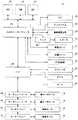
図3には歩行補助ロボット10の電気的な構成の一例を示すブロック図が示される。歩行補助ロボット10は、全体の制御のためにマイクロコンピュータまたはCPU50を含み、このCPU50には、バスを介して、RAM52、HDD54および入出力インターフェース56が接続される。 FIG. 3 is a block diagram showing an example of the electrical configuration of the walking assist
HDD54や図示しないROMには、この歩行補助ロボット10の動作を制御するプログラムおよびデータが予め格納されている。RAM52はバッファメモリやワーキングメモリとして使用される。CPU50は、HDD54から必要なプログラムおよびデータをRAM52に読み出し、当該プログラムに従って生成しまたは取得したデータをRAM52に記憶しつつ処理を実行する。 A program and data for controlling the operation of the walking assist
入出力インターフェース56は、接続される各機器に適した回路およびインターフェースを含む。CPU50には、入出力インターフェース56を介して、LCD38、タッチパネル40、無線通信装置58、アンプ60、触覚センサ48、距離センサ22、GPS受信機62およびハブ64が接続される。 The input /
CPU50は、表示する画面のデータを入出力インターフェース56を介して図示しないLCDコントローラに与え、当該画像をLCD38に表示する。タッチパネル40は、ユーザによってタッチされた位置を検出して当該位置を示す座標データを出力する。CPU50は入出力インターフェース56を介してタッチパネル40からの座標データを取得する。 The
無線通信装置58は他の装置と無線通信するためのものであり、たとえば無線LANアクセスポイントや基地局などを介してネットワークの他の装置と通信する。CPU50は無線通信装置58を介してデータを送受信する。 The
アンプ60にはスピーカ34が接続される。CPU50は音声データを入出力インターフェース56に与え、アンプ60を介して左右のスピーカ34のそれぞれに音声信号を与えて当該音声を出力する。 A
触覚センサ48は、上述のように複数のセンサデバイス、複数の読取装置および複数の演算装置などを備えたセンサネットワークであり、センサデバイスの識別情報と圧力情報等を含む触覚情報を出力する。CPU50は入出力インターフェース56を介して触覚センサ48からの出力データを取得する。 The
距離センサ22は、検出した物体までの距離ないし位置に関する情報を当該距離センサ22の識別情報とともに出力し、CPU50は入出力インターフェース56を介して距離センサ22からの出力データを取得する。なお、上述のようにこの歩行補助ロボット10には複数の距離センサが設置されるが、図3ではこれらをまとめて距離センサ22として示す。 The
GPS受信機62は、4つのGPS衛星またはディファレンシャルGPS基準局からの信号を受信して、現在地の緯度、経度、高度を算出し、現在の位置情報を出力する。CPU50は入出力インターフェース56を介してGPS受信機62からの出力データを取得する。 The
ハブ64はたとえばUSB2.0ハブであり、ハブ64には、タグリーダ66、カメラ44、マイク46およびサーボコントローラ68が接続される。 The
タグリーダ66は、無線タグ(RFIDタグ)から発信されるデータを読み取るためのものであり、CPU50は入出力インターフェース56およびハブ64を介してタグリーダ66からの出力データを取得する。なお、環境に埋め込まれる無線タグやユーザに取り付けられる無線タグにパッシブ型無線タグが使用される場合には、タグリーダ66がアンテナから電波を発信して、電磁誘導で当該無線タグを駆動する。 The
なお、赤外線LEDタグが使用される場合には、赤外線LEDタグの発信する情報を読み取るために、赤外線カメラないし赤外線受光素子などを備えるタグリーダが設けられる。 When an infrared LED tag is used, a tag reader including an infrared camera or an infrared light receiving element is provided to read information transmitted from the infrared LED tag.
カメラ44は撮影した映像に基づく画像データを出力し、CPU50は入出力インターフェース56およびハブ64を介してカメラ44からの出力データを取得する。マイク46は入力された声または音に基づく音声データを出力し、CPU50は入出力インターフェース56およびハブ64を介してマイク46からの出力データを取得する。 The
サーボコントローラ68は、たとえばUSBシリアル変換ケーブルを用いてハブ64に接続される。サーボコントローラ68には、サーボコントローラ70、モータドライバ72およびモータドライバ74がたとえばデイジーチェーンで接続される。 The
サーボコントローラ68は操作部36を駆動するための首サーボモータ76を制御する。つまり、サーボコントローラ68はCPU50からの制御データを受けて、操作部36のヨー軸A周りの角度を制御する1つのモータ(すなわち「首サーボモータ」)76の回転角度を調節する。また、サーボコントローラ70は球体42を駆動するための顔サーボモータ78を制御する。つまり、サーボコントローラ70は、CPU50からの制御データを受けて、球体42のヨー軸Bおよびピッチ軸C周りの各角度を制御する2つのモータ(まとめて「顔サーボモータ」と呼ぶ。)78の回転角度を調節する。このように、CPU50は、サーボコントローラ68および70に適切な制御データを与えることによって、操作部36の向きを所望の方向に制御できるし、球体42の向き、すなわち、これに取り付けられたカメラ44およびマイク46の向きを所望の方向に制御できる。 The
また、モータドライバ72は、CPU50からの制御データを受けて、後輪12aを駆動するための後輪モータ16を制御する。後輪モータ16は、後輪12aを回転させるための駆動用モータと、後輪12aを操舵するための操舵用モータとを含む。したがって、モータドライバ72は後輪12aの方向および回転を制御できる。なお、各モータの動力は各減速機を介して車輪12aに伝達される。また、モータドライバ74は、CPU50からの制御データを受けて、前輪12aを駆動するための前輪モータ14を制御する。前輪モータ14は、前輪12aを回転させるための駆動用モータと、前輪12aを操舵するための操舵用モータとを含む。したがって、モータドライバ74は前輪12aの方向および回転を制御できる。このように、CPU50は、モータドライバ72および74に適切な制御データを与えることによって、歩行補助ロボット10の移動方向、移動距離(移動速度)などを制御できる。 The
たとえば、この歩行補助ロボット10は、人間を連れて移動する際、環境のインフラと連携して現在地を把握しつつ移動をすることができる。利用する環境のインフラは、代表的にはGPSであり、また、ネットワークロボット技術等である。 For example, when the walking assist
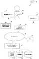
図4には、歩行補助ロボット10と環境のインフラとの連携の概要の一例が示される。歩行補助ロボット10が利用する環境インフラとして、ネットワーク80を介して接続可能なネットワークロボットプラットフォーム(以下、単に「プラットフォーム」ともいう。)82、ネットワーク80に接続するための無線LANアクセスポイント84、環境埋め込み型情報発信機器86、ネットワーク80に接続されている他のロボット88、およびGPS衛星90等が存在する。なお、無線LANアクセスポイント84は基地局であってもよい。また、歩行補助ロボット10は4つのGPS衛星90からの信号を受信することによって高精度に現在地を検出できるが、ディファレンシャルGPS基準局の発信する補正情報を使用してもよい。 FIG. 4 shows an example of the outline of cooperation between the walking assist
プラットフォーム82は、ネットワーク80に接続されている各種ロボットやアンコンシャスセンサなどのようなロボット88が計測した情報を登録するデータベースである。この歩行補助ロボット10や他のロボット88はプラットフォーム82に登録されているデータをネットワーク80経由で受信して利用することができる。また、この歩行補助ロボット10が計測した情報も、プラットフォーム82に登録することができる。プラットフォーム82は、たとえばロボット位置情報DB(データベース)82a、人位置情報DB82bおよび位置付属情報DB82cなどを含む。ロボット位置情報DB82aには、ネットワークに接続されている各ロボットの現在位置を示すデータが記憶され、この歩行補助ロボット10の位置データもその識別情報に対応付けて登録されている。人位置情報DB82bには、計測対象に設定された人の現在位置を示すデータが記憶され、この歩行補助ロボット10のユーザの位置データもその識別情報に対応付けて登録されてよい。位置付属情報DB82cには、たとえば、位置データ(緯度、経度、高度)または位置の識別情報に対応付けて、当該位置に関してユーザに提供すべき情報が記憶されている。一例として、転びやすい、車がよく通って危ないなど、歩行者に警告ないし提示すべき情報が登録される。位置付属情報は、当該情報を音声出力で提供する場合には音声データであってよいし、当該情報を画面表示で提供する場合には画像データまたはテキストデータ等であってよい。あるいは、提供される複数の情報について、歩行補助ロボット10に音声データまたは画像データもしくはテキストデータ等を予め記憶しておく場合には、位置付属情報DB82cには、当該情報の識別情報を登録しておくようにしてもよい。 The
歩行補助ロボット10は、屋外を移動しながら、たとえば公衆無線LANの無線LANアクセスポイント84に通信接続して、ネットワーク80を介してプラットフォーム82にアクセスできる。また、歩行補助ロボット10は、屋内では、たとえば当該建物内の無線LANの無線LANアクセスポイント84に通信接続して、ネットワーク80を介してプラットフォーム82にアクセスできる。 The walking
歩行補助ロボット10は、環境埋め込み型の情報発信機器86からの情報を取得する。環境埋め込み型情報発信機器86は、たとえば、環境中に埋め込まれたインテリジェント基準点や、ICタグ付き点字ブロック、無線マーカ、赤外線マーカなどの情報発信機器である。インテリジェント基準点は、国土地理院によって設置される位置情報の基準となる基準点であり、無線タグなどの情報発信機器が設定される。各情報発信機器86は、屋内または屋外の所定の位置に設置され、当該機器の設置された位置情報を電波または赤外線等を用いて発信する。なお、無線タグが使用される場合パッシブ型であることが望ましい。ただし、外部電源を容易に確保できる場所であればこれに限られない。発信される位置情報は、当該埋め込み位置の識別情報であり、歩行補助ロボット10はタグリーダ66で当該識別情報を読み取ると、無線通信装置58を用いてネットワーク80経由でプラットフォーム82に当該識別情報を送信する。プラットフォーム82は、位置の識別情報を受信すると、たとえばネットワーク80に接続された他のデータベースから、当該識別情報に対応付けられた位置データ(緯度、経度、高度)を取得して、歩行補助ロボット10の識別情報に対応付けて当該位置データをロボット位置情報DB82aに記憶する。 The walking
なお、情報発信機器86は、当該位置の識別情報を発信せずに、当該位置の緯度、経度および高度を示す位置データ自体を発信するようにしてもよい。この場合には、歩行補助ロボット10は情報発信機器86から現在地の位置データを直接取得できるし、また、現在地の位置データをプラットフォーム82に送信してロボット位置情報DB82aに登録できる。 The
ユーザには当該ユーザの識別情報を発信するタグ92が装着される。タグ92は無線タグであり、場合によっては赤外線LEDタグであってもよい。歩行補助ロボット10は、タグ92を検出したとき、当該読み取ったユーザ識別情報をプラットフォーム82に送信する。プラットフォーム82はユーザ識別情報を受信すると、たとえば、当該ユーザ識別情報を送信してきたロボットの現在地をロボット位置情報DB82aから取得し、当該位置データを当該ユーザ識別情報に対応付けて人位置情報DB82bに記憶する。あるいは、歩行補助ロボット10が現在地を把握している場合、検出したユーザ識別情報とともに現在地の位置データをプラットフォーム82に送信するようにしてもよい。 A
他のロボット88は、ビジブル型ロボットや環境に埋め込まれたアンコンシャス型ロボットであり、人に装着されたタグ92を検出するタグリーダを備えている。ビジブル型ロボットは、目に見えるロボットで、人型、ペット型など一体性のある身体を持つ。自律的または遠隔操作などで行動するパートナーロボットや、情報提供ないしガイドを行うサポートロボット等がこれに相当する。アンコンシャス型ロボットは、道路、街、室内、機器などの環境に埋め込まれたロボットであり、身体が見えないロボットをいう。人間の行動モニタリングをベースに必要に応じた情報を提供する。このような他のロボット88も、タグ92を検出すると、歩行補助ロボット10と同様に、当該読み取ったユーザ識別情報をネットワーク80経由でプラットフォーム82に送信する。これに応じて、プラットフォーム82は、上述の歩行補助ロボット10が送信した場合と同様にして、ユーザ識別情報に対応付けて位置データを人位置情報DB82bに記憶する。 The
なお、この実施例では、歩行補助ロボット10にタグは装着されない。しかし、他の実施例では、歩行補助ロボット10にタグが装着されてもよい。この場合には、他のロボット88は、歩行補助ロボット10のタグを検出すると、当該読み取った歩行補助ロボット10の識別情報をネットワーク80経由でプラットフォーム82に送信する。したがって、この場合には、歩行補助ロボット10の現在地を他のロボット88によって検出し、プラットフォーム82に登録することができる。 In this embodiment, no tag is attached to the walking assist
また、このプラットフォーム82を備えるシステムでは、歩行補助ロボット10のユーザの家族の人等は、ネットワーク80に接続されたPC94からプラットフォーム82にアクセスして歩行補助ロボット10またはユーザの識別情報を入力することによって、当該歩行補助ロボット10またはユーザの現在地を確認することができる。なお、PC94はネットワーク80に接続可能な携帯端末や携帯電話であってもよい。 In the system including the
このように、歩行補助ロボット10は、GPS衛星90、ネットワーク80、プラットフォーム82、環境埋め込み型情報発信機器86等の環境インフラを利用することによって、屋内屋外を問わず現在地を把握することができるので、ユーザを目的地まで正確に案内することができる。しかも、ユーザを搭乗させた移動ではなく、たとえばつかみ部30につかまってまたは当該歩行補助ロボット10に接触せずに歩行するユーザを連れた移動を実現することができるので、ユーザの健康を促進できる。 As described above, the walking assist
この歩行補助ロボット10の誘導処理における具体的な動作を、図5のフロー図を参照しながら説明する。誘導処理を開始すると、歩行補助ロボット10のCPU50は、ステップS1で、プラットフォーム82またはGPS等から現在地の位置データを取得する。位置データは、たとえば緯度、経度、高度(標高)である。具体的には、無線通信装置58を用いて無線LANアクセスポイント84と通信接続できたときには、ネットワーク80を介してプラットフォーム82に現在地の要求を送信する。これに応じて、プラットフォーム82は、受信した歩行補助ロボット10の識別情報に対応する位置データをロボット位置情報DB82aから読み出して、当該位置データを当該歩行補助ロボット10にネットワーク80を介して送信する。これに応じて、歩行補助ロボット10は現在地の位置データを受信してRAM52に記憶する。または、GPS受信機62から出力される位置データを取得してRAM52に記憶する。あるいは、タグリーダ66を使用して環境埋め込み型情報発信機器86を検出できた場合には、当該情報発信機器86が位置データを発信しているときには、当該位置データを現在地としてRAM52に記憶してもよい。なお、環境埋め込み型情報発信機器86が位置データではなく位置の識別情報を発信しているときには、当該識別情報をネットワーク80を介してプラットフォーム82に送信する。これに応じて、プラットフォーム82は、当該識別情報に対応する位置データを特定して、当該位置データを当該歩行補助ロボット10に返信する。また、プラットフォーム82は、当該歩行補助ロボット10の識別情報に対応付けてロボット位置情報DB82aに当該位置データを記憶する。また、歩行補助ロボット10がユーザのタグ92を検出して当該ユーザ識別情報も送信している場合には、プラットフォーム82は当該ユーザの識別情報に対応付けて人位置情報DB82bに当該位置データを記憶する。 A specific operation in the guidance process of the walking assist
次に、ステップS3で、目的地入力処理を実行する。この処理では、コミュニケーションによってユーザに目的地を入力してもらう。この実施例では、ユーザは音声発話またはタッチパネル40の操作によって目的地を設定できる。この目的地入力処理の動作の一例が図6に示される。目的地入力処理が開始されると、LCD38には目的地設定の開始を指示するための起動ボタンが表示される。図6のステップS21で、起動ボタンがタッチされたか否かを、タッチパネル40からの座標データと起動ボタンの位置データとに基づいて判定する。なお、LCD38に表示されるボタンやアイコンなどの位置データは予めHDD54に記憶されており、処理の開始時など必要に応じてRAM52に読み出されている。ステップS21で“NO”であれば、ステップS23で、触覚センサ48が触られているか否かを、触覚センサ48から取得した触覚情報によって判定する。ステップS23で“NO”であれば処理はステップS21に戻る。 Next, in step S3, a destination input process is executed. In this process, the user inputs a destination by communication. In this embodiment, the user can set the destination by voice utterance or operation of the
一方、ステップS21で“YES”である場合、またはステップS23で“YES”である場合には、ステップS25で、たとえば「目的地を教えて下さい」のようなメッセージの画像ないし文字をLCD38に表示し、また、同メッセージの音声をスピーカ34から出力する。なお、LCD38に画面を表示するための画像データおよびスピーカ34から音声を出力するための音声データは予めHDD54に記憶される。 On the other hand, if “YES” in the step S21 or “YES” in the step S23, a message image or character such as “Tell me your destination” is displayed on the
そして、ステップS27で、歩行者すなわちユーザの音声発話またはタッチパネル40の操作に応じて目的地を設定する。具体的には、マイク46によって取得された音声データに音声認識を行うことによってユーザの発話した目的地を認識する。または、LCD38に、目的地を名称または住所などから選択または指定可能な目的地設定用画面を表示しておく。そして、タッチパネル40からの座標データと画面に表示されているボタンやアイコン等の位置データとに基づいて、ユーザによって指示ないし選択された目的地を特定する。入力された目的地の位置データ(緯度、経度、高度)は、HDD54に記憶されていた地図データから取得され、目的地データとしてRAM54に記憶される。なお、目的地として、その緯度、経度、高度が入力されてもよい。ステップS27を終了すると、この目的地入力処理を終了して処理は図5のステップS5へ戻る。 In step S27, the destination is set according to the voice utterance of the pedestrian, that is, the user or the operation of the
図5のステップS5では、現在地から目的地までの経路を、探索用経路に関する情報を含む地図データに基づいて探索して、移動経路情報を生成し、RAM52記憶する。なお、地図データは予めHDD54に記憶されている。現在地から目的地までの経路の探索および生成は、公知のカーナビゲーションシステムなどの手法を使用すればよい。なお、この実施例では、歩行補助ロボット10で経路を探索および生成するようにしているが、他の実施例では、目的地までの移動経路情報をネットワーク80から取得するようにしてもよい。たとえば、現在地と目的地の情報をネットワーク80上の経路探索用サーバに送信して、当該サーバが地図データに基づいて現在地から目的地までの経路の探索および生成を行って、当該移動経路情報を歩行補助ロボット10に送信するようにしてもよい。なお、プラットフォーム82に上記経路探索用サーバとしての機能を備えさせてもよい。この場合、プラットフォーム82は歩行補助ロボット10の現在地だけでなく目的地も把握することができる。 In step S5 of FIG. 5, a route from the current location to the destination is searched based on map data including information related to the search route, travel route information is generated, and stored in the
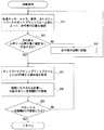
そして、ステップS7で移動処理を実行する。これによって、作成した経路に沿って歩行者と共に移動する。この移動処理では、歩行者と当該歩行補助ロボット10との位置関係を所定の範囲内に保つように位置調整を行いながら、経路に沿う方向に一定距離だけ進む移動が行われ、当該移動処理を繰返すことによって目的地まで歩行者を誘導する。この移動処理の動作の一例が図7に示される。 And a movement process is performed by step S7. Thereby, it moves with the pedestrian along the created route. In this movement process, the position is adjusted so that the positional relationship between the pedestrian and the walking assist
移動処理を開始すると、ステップS41で、たとえば触覚センサ48、カメラ44および音声、またはプラットフォーム82を用いて、歩行者の位置を確認する。具体的には、触覚センサ48からの触覚情報に基づいて歩行者が歩行補助ロボット10に触っているか否かを判定し、反応がある場合には歩行者が歩行補助ロボット10から離れていない、つまり、当該ロボット10の声が届く範囲内に存在していることが確認できる。また、顔サーボモータ78および首サーボモータ76を制御してカメラ44で全方向を撮影することによって取得した画像データに基づいて歩行者の特徴(予め設定しておいた服の色など)の検出を行う。歩行者の特徴が検出される場合には当該歩行者が歩行補助ロボット10から離れていないことが確認できる。また、スピーカ34からの音声出力によって歩行者の名前を呼びかけたり話しかけたりして、歩行者からの応答をマイク46で取得した音声データから検出する。応答が検出される場合には当該歩行者が歩行補助ロボット10から離れていないことが確認できる。または、プラットフォーム82に歩行者の識別情報を含む要求を送信して、プラットフォーム82から当該歩行者の現在地を示す位置データを取得する。そして、当該歩行補助ロボット10の現在地と歩行者の現在地から両者の距離を算出し、当該算出距離が所定の閾値以下であるか否かを判定する。なお、所定の閾値は、たとえば当該ロボット10の出力音声が届く最大距離を実験によって計測することで得られる。なお、ステップS41では、距離センサ22で歩行者との距離を計測するようにしてもよい。または、後述する他の実施例のような歩行者位置検出処理(図9)を実行してもよい。 When the movement process is started, in step S41, for example, the position of the pedestrian is confirmed by using the
次に、ステップS43で、歩行者が当該歩行補助ロボット10の声の届く範囲内に存在しているか否かを判定し、“NO”であれば、ステップS45で歩行者の近隣に移動する。たとえば、プラットフォーム82から取得した歩行者の現在地、当該ロボット10の現在地および向き(進行方向)等から、歩行者の近隣に設定した目標位置へ向かうための方向と距離とを算出する。そして、当該算出した方向および距離の移動を行うための制御データを生成し、当該制御データをモータドライバ72および74に与えて、後輪モータ16および前輪モータ14の回転を制御する。これによって、ユーザと離れないように位置関係を調整することができるので、ユーザを連れて移動することができる。ステップS45を終了すると処理はステップS41に戻って歩行者の位置を確認する。 Next, in step S43, it is determined whether or not the pedestrian is within the range where the voice of the walking assist
一方、ステップS43で“YES”であれば、つまり、歩行者が歩行補助ロボット10の近くに存在している場合には、作成した経路に沿った一定距離Aの移動を行う。具体的には、ステップS47で、上述のステップS1と同様にして、プラットフォーム82またはGPS等から歩行補助ロボット10の現在地を取得する。続いて、ステップS49で、現在地の位置データと作成した経路データに基づいて当該経路に沿う方向を計算し、当該方向へ一定距離Bだけ移動する。具体的には、算出した方向および一定距離Bの移動を行うための制御データを生成し、当該制御データをモータドライバ72および74に与えて、後輪モータ16および前輪モータ14の回転を制御する。なお、制御データの生成では、設定された移動速度も考慮される。移動速度はデフォルトであってもよいが、たとえば、ユーザの発話またはタッチパネル操作によって予め複数の候補から選択されたり入力されたりしてもよい。また、一定距離AおよびBの値は適宜に設定される。ただし、距離Bの値は距離Aの値よりも小さい。そして、ステップS51で、歩行補助ロボット10は今回の移動処理を開始してから一定距離Aだけ移動したか否かを判定する。ステップS51で“NO”であれば処理はステップS47へ戻り、一方、“YES”であればこの移動処理を終了して、処理は図5のステップS9へ戻る。このようにして、距離Bの移動ごとに経路に沿うように移動方向が決められ、当該方向への移動が行われる。また、移動処理が開始されるたびに、歩行者の位置が確認され、離れている場合には歩行補助ロボット10は歩行者に近付いて、位置調整を行う。 On the other hand, if “YES” in the step S43, that is, if the pedestrian is present in the vicinity of the walking assist
図5のステップS9では、目的地に到着したか否かが判定される。たとえば、GPSまたはプラットフォーム82等の環境インフラから現在地の位置データを取得して、現在地の位置データと目的地の位置データとが一致するか否かを判定する。現在地が目的地から所定距離内であれば両者は一致すると判定してよい。ステップS9で“NO”であれば、処理はステップS7へ戻って再び移動処理を行う。 In step S9 of FIG. 5, it is determined whether the destination has been reached. For example, the current location data is acquired from environmental infrastructure such as GPS or
このようにして、目的地に到着するまでは、距離Aの移動ごとに歩行者の位置が確認されるとともに、距離Bの移動ごとに経路に沿った方向が決められて移動が行われる。したがって、この実施例によれば、歩行者を連れて移動することができるとともに、歩行者を目的地まで正確に誘導することができる。 In this way, the position of the pedestrian is confirmed for each movement of the distance A and the direction along the route is determined for each movement of the distance B until the arrival at the destination. Therefore, according to this embodiment, while being able to move with the pedestrian, the pedestrian can be accurately guided to the destination.
なお、移動速度は一定にされてもよいが、他の実施例では、歩行者に合わせて移動速度を調整するようにしてもよい。たとえば、歩行者の状態(位置および姿勢など)の変化や歩行者と歩行補助ロボット10との距離の変化などに応じて、速度が調整されてよい。 In addition, although a moving speed may be made constant, in another Example, you may make it adjust a moving speed according to a pedestrian. For example, the speed may be adjusted according to a change in a pedestrian's state (position and posture, etc.), a change in the distance between the pedestrian and the walking assist
図8には速度調整処理の動作の一例が示される。この速度調整処理は、たとえば、一定時間ごとに他の処理(移動処理)と並列的に実行されてもよいし、図5のステップS7の移動処理の終了後に実行されてもよいし、所定の距離の移動ごとに実行されてもよい。 FIG. 8 shows an example of the operation of the speed adjustment process. This speed adjustment processing may be executed in parallel with other processing (movement processing) at regular intervals, for example, or may be executed after the completion of the movement processing in step S7 in FIG. It may be executed for each movement of the distance.
速度調整処理を開始すると、ステップS61で、歩行者位置検出処理が実行され、当該歩行補助ロボット10と一緒に移動している人の位置が検出される。この歩行者位置検出処理の動作の一例が図9に示される。 When the speed adjustment process is started, a pedestrian position detection process is executed in step S61, and the position of the person moving with the walking assist
図9のステップS91で、タグリーダ66を用いて周囲を計測し、歩行者に装着されるタグ92の検出を試みる。歩行者に装着されるタグ92は、たとえばパッシブ型の無線タグであり、タグリーダ66の放つ電波で駆動されて、識別情報を発信する。この種のタグの交信可能範囲はたとえば1m程度の短距離であり、したがって、ここでは短距離で反応する無線タグが検出され得る。 In step S91 of FIG. 9, the circumference is measured using the
次に、ステップS93で、対象としている人のIDが存在するか否かを判定する。つまり、歩行者のIDを検出できたか否かを判断する。歩行者の所持するタグ92の識別情報すなわちIDは、当該歩行者の識別情報に対応付けて、予めまたは移動前に歩行補助ロボット10に登録される。あるいは、タグ92は、歩行者の識別情報を発信してもよい。ステップS93で“NO”であれば、つまり、歩行者が近くにいない場合には、ステップS95で、音声発話によって、対象としている人の名前を呼びかける。たとえば、歩行者の名前は、移動前にタッチパネル操作等によって歩行補助ロボット10に登録されている。当該名前を発音する合成音声データが生成されて当該名前の音声が出力される。これによって、歩行者を歩行補助ロボット10の方へ近付けさせる。ステップS95を終了すると処理はステップS91に戻る。 Next, in step S93, it is determined whether or not the ID of the target person exists. That is, it is determined whether or not the pedestrian ID has been detected. The identification information of the
一方、ステップS93で“YES”であれば、つまり、歩行者が当該歩行補助ロボット10の近距離範囲内に存在している場合には、ステップS97で、触覚センサ48からの触覚情報を取得して、触覚センサ48が触られているか否かを判定する。 On the other hand, if “YES” in the step S93, that is, if the pedestrian is present within the short distance range of the walking assist
なお、タグリーダ66で歩行者のIDを検出した場合には、当該歩行者IDをネットワーク80を介してプラットフォーム82に送信し、人位置情報DB82bに当該歩行者の位置を記録させるようにしてよい。 When the
ステップS97で“YES”であれば、つまり、歩行者が歩行補助ロボット10に触っている場合には、ステップS99で、取得した触覚情報とHDD54に記憶されているマップデータとに基づいて、歩行補助ロボット10に触れている歩行者の位置および姿勢を推定する。 If “YES” in the step S97, that is, if the pedestrian is touching the walking assist
続いて、ステップS101で、推定した位置および姿勢から当該歩行者の顔の位置を推定して、当該顔の位置をカメラ44で確認する。具体的には、推定した顔の位置にカメラ44を向けるための制御データを生成し、当該制御データをサーボコントローラ68および70に与えて、首サーボモータ76および顔サーボモータ78の回転を制御し、球体42すなわちカメラ44を当該顔の位置へ向ける。そして、カメラ44からの画像データを取得して、当該画像データに基づいて歩行者の顔(たとえば肌色領域あるいは顔の特徴)の検出を試みる。 Subsequently, in step S101, the position of the face of the pedestrian is estimated from the estimated position and posture, and the position of the face is confirmed by the
そして、ステップS103で、歩行者が推定位置に存在するか否かを判断する。このステップS103で“NO”であれば、つまり、触覚情報から推定した位置に歩行者が存在していない場合には、処理はステップS105へ進む。一方、ステップS103で“YES”であれば、処理はステップS109へ進む。また、ステップS97で“NO”であれば、つまり、歩行者が歩行補助ロボット10に触れていない場合には、処理はステップS105へ進む。 In step S103, it is determined whether a pedestrian is present at the estimated position. If “NO” in this step S103, that is, if a pedestrian is not present at the position estimated from the tactile information, the process proceeds to a step S105. On the other hand, if “YES” in the step S103, the process proceeds to a step S109. If “NO” in the step S97, that is, if the pedestrian is not touching the walking assist
ステップS105では、カメラ44などで歩行補助ロボット10の周囲360度全てを計測する。たとえば、サーボコントローラ68を用いて首サーボモータ76を制御してヨー軸A周りで操作部36を回転して後方に向ける。そして、サーボコントローラ70を用いて顔サーボモータ78を制御してヨー軸Bおよびピッチ軸C周りで球体42すなわちカメラ44の向きを変化させながら、歩行補助ロボット10の後方の全範囲を撮影する。さらに、サーボコントローラ68を用いて首サーボモータ76を制御してヨー軸A周りで操作部36を回転して前方に向けて、その後同様に球体42の向きを変化させながら、歩行補助ロボット10の前方の全範囲を撮影する。 In step S105, all 360 degrees around the walking assist
続いて、ステップS107で、撮影した画像データに基づいて、対象としている人の特徴と合致する人の位置を検出する。タグ92の検出により歩行者が当該歩行補助ロボットの近くに存在していることは確認されているので、全方向の撮影によって歩行者の位置を検出することが可能である。対象としている人すなわち歩行者の特徴はたとえばその服の色であってよい。当該特徴は、たとえば、移動前にカメラ44で撮影することによってHDD54またはRAM52に記憶されてよい。全方向の画像のうち特徴の検出された画像が撮影されたときの各軸のサーボモータの回転角度、および当該画像における特徴の位置などから、人の位置を特定する。 Subsequently, in step S107, based on the captured image data, the position of a person that matches the characteristics of the target person is detected. Since it is confirmed by the detection of the
続くステップS109では、検出した位置に当該歩行補助ロボット10の顔すなわち球体42を向けて、音声発話により話しかける。そして、ステップS111で、検出した位置に対象としている人が存在するか否かを判定する。具体的には、ステップS109における顔を向けての話しかけに対して、歩行者から所定の反応があったか否かを判定する。顔を向けられて話しかけられたとき、人間は何らかの反応を返すことが予期されるので、当該予期される反応の認識を行う。代表的には、話しかけに対する発話があったか否かをマイク46から取得したデータに基づいて判定する。ステップS111で“NO”であれば、顔を向けた位置には歩行者が存在していないと考えられるので、処理はステップS105に戻って人の位置の検出からやり直す。一方、ステップS111で“YES”であれば、人の位置を確認できたのでこの歩行者位置検出処理を終了して、処理は図8のステップS63に戻る。 In the subsequent step S109, the face of the walking assist
続いて、図8のステップS63で、触覚センサ48から取得した触覚情報に基づいて触覚センサ48に反応があるか否かを判定する。ステップS63で“YES”であれば、つまり、歩行者が歩行補助ロボット10に触れている場合には、ステップS65で、触覚センサ48の出力とマップから推定される歩行者の位置および姿勢を、たとえば現時刻に対応付けてRAM52に記録する。これによって、歩行者の位置および姿勢について、所定回数分の履歴(少なくとも今回と前回)を記録する。そして、ステップS67で、歩行者の位置および姿勢の変化が激しいか否かを判定する。歩行者の歩行ペースと歩行補助ロボット10の移動ペースとが合っていない場合には、歩行補助ロボット10に触れている歩行者は、歩行補助ロボット10に近付き過ぎたり遠ざかり過ぎたりして、その位置および姿勢を大きくまたは頻繁に変えることになると考えられる。したがって、ここでは、歩行者の歩行補助ロボット10に対する触行動に基づいて推定される位置および姿勢の変化に着目して、速度変更の必要性を判定している。 Subsequently, in step S63 of FIG. 8, it is determined whether or not there is a response to the
ステップS67で“YES”であれば、ステップS69で速度変更処理を実行し、“NO”であれば、ステップS71で現在の移動速度を維持する。ステップS69の速度変更処理の動作は後述される。 If “YES” in the step S67, a speed changing process is executed in a step S69, and if “NO”, the current moving speed is maintained in a step S71. The operation of the speed change process in step S69 will be described later.
一方、ステップS63で“NO”であれば、つまり、歩行者が歩行補助ロボット10に触れていない場合には、ステップS73で、距離センサ22などによって歩行者との距離を計測して、当該距離をたとえば現時刻に対応付けてRAM52に記録する。ステップS61の歩行者位置検出処理で歩行者の位置が検出されているので、当該歩行者の位置に向けられている距離センサ22からの計測データを元に距離を記録する。これによって、歩行者と歩行補助ロボット10との距離について、所定回数分の履歴(少なくとも今回と前回)を記録する。そして、ステップS75で、歩行者との距離が変化しているか否かを判断する。歩行者の歩行ペースと歩行補助ロボット10の移動ペースとが合っていない場合には、歩行者は、歩行補助ロボット10に近付いたり遠ざかったりして、両者間の距離が変化することになると考えられる。したがって、ここでは、歩行者と歩行補助ロボット10との距離の変化に着目して、速度変更の必要性を判定している。 On the other hand, if “NO” in the step S63, that is, if the pedestrian is not touching the walking assist
ステップS75で“YES”であれば、ステップS69で速度変更処理を実行し、“NO”であれば、ステップS77で現在の移動速度を維持する。ステップS69の速度変更処理の動作は後述される。ステップS71、S77またはS69を終了すると、この速度調整処理を終了する。 If “YES” in the step S75, a speed changing process is executed in a step S69, and if “NO”, the current moving speed is maintained in a step S77. The operation of the speed change process in step S69 will be described later. When step S71, S77 or S69 ends, the speed adjustment processing ends.
ステップS69の速度変更処理の動作の一例が図10に示される。図10のステップS121で、対象としている人に向けて、たとえば「ゆっくり移動しますか?」と発話する。具体的には、図9の歩行者位置検出処理におけるステップS109と同様に、当該位置に顔すなわち球体42を向けるとともに、上記音声をスピーカ34から出力する。 An example of the operation of the speed change process in step S69 is shown in FIG. In step S121 of FIG. 10, for example, “Do you move slowly?” Is spoken toward the target person. Specifically, similarly to step S109 in the pedestrian position detection process of FIG. 9, the face, that is, the
続いて、ステップS123で、上記発話に対して肯定する返答が得られたか否かを、マイク46からの音声入力データの音声認識によって判定する。ステップS125で“YES”であれば、ステップS125で移動速度を減少する。たとえば、現在の移動速度の値から一定値だけ減算して、当該新たな移動速度をRAM52に記憶する。 Subsequently, in step S123, it is determined by voice recognition of voice input data from the
一方、ステップS123で“NO”であれば、つまり、否定的な返答が得られた場合、または一定時間経過しても返答が得られなかった場合等には、ステップS127で、対象としている人に向けて、たとえば「はやく移動しますか?」と発話する。そして、ステップS129で、上記発話に対して肯定する返答が得られたか否かを判定する。ステップS129で“YES”であれば、ステップS131で移動速度を増加する。たとえば、現在の移動速度の値に一定値を加算し、当該新たな移動速度をRAM52に記憶する。 On the other hand, if “NO” in the step S123, that is, if a negative response is obtained, or if a response is not obtained even after a lapse of a certain time, the target person in the step S127. For example, say "Do you want to move quickly?" In step S129, it is determined whether or not an affirmative reply has been obtained for the utterance. If “YES” in the step S129, the moving speed is increased in a step S131. For example, a fixed value is added to the current moving speed value, and the new moving speed is stored in the
また、ステップS129で“NO”であれば、つまり、否定的な返答が得られた場合、または一定時間経過しても返答が得られなかった場合には、ステップS133で現在の移動速度を維持する。ステップS125、S131またはS133を終了すると、この速度変更処理を終了する。このようにして、歩行補助ロボット10と歩行者とのコミュニケーションによって、簡単に速度を変更することができる。 If “NO” in the step S129, that is, if a negative response is obtained, or if a response is not obtained even after a predetermined time has passed, the current moving speed is maintained in the step S133. To do. When step S125, S131, or S133 ends, the speed change process ends. In this way, the speed can be easily changed by communication between the walking assist
したがって、図8の速度調整処理によれば、歩行者の状態を見ながら歩行ペースを調整することができるので、歩行者を連れて歩行者に合わせたペースで移動することができる。 Therefore, according to the speed adjustment process of FIG. 8, the walking pace can be adjusted while looking at the state of the pedestrian, so that the pedestrian can be moved at a pace that matches the pedestrian.
また、上述の各実施例の歩行補助ロボット10には座部24を設けて、移動に疲れた歩行者が当該歩行補助ロボット10の移動を停止させて、当該座部24に座って休憩することができるようにしている。つまり、座部24は、人間を搭乗させて移動させるためのものではなく、歩行補助ロボット10を休憩用椅子として機能させる。したがって、他の実施例では、ユーザが歩行補助ロボット10を椅子として扱って座部24に腰掛けたときには、目的地への移動などの長距離移動を自動的にキャンセルするようにしてよい。この機能を実現するための休止処理の動作の一例が図11に示される。この休止処理は、たとえば、図5の誘導処理と並列的に、一定時間ごとに実行される。 In addition, the walking assist
図11のステップS151では、距離センサ22や圧力センサ等で椅子上を計測する。たとえば、この実施例の歩行補助ロボット10では、座部24の上方をセンシングするように、支柱26などにおける適宜な位置に距離センサ22が設置される。したがって、当該座部24上をセンシングする距離センサ22からのデータを取得する。また、座部24に圧力センサまたは接触センサ等を設置し、座部24上に物体が置かれたことを検知するようにしてもよい。この場合、当該圧力センサ等からの出力データを取得する。あるいは、上述の触覚センサ48を座部24の上面にも設けるようにしてもよい。この場合、触覚センサ48からの出力データを取得して、当該データから座部24上のセンサデバイスのデータを取得する。 In step S151 in FIG. 11, the chair is measured by the
そして、ステップS153で、計測したデータに基づいて、椅子上に物体が存在するか否かを判定する。なお、距離センサ22の場合には、計測された物体までの距離が座部24の上方の範囲内であるか否かを判定する。ステップS153で“NO”であれば、座部24上に物体がないので、そのままこの休止処理を終了する。 In step S153, it is determined whether an object exists on the chair based on the measured data. In the case of the
一方、ステップS153で“YES”であれば、つまり、座部24上に何らかの物体が存在する場合には、当該座部24上の物体がユーザであるか否かを確認するために、ステップS155で歩行者位置検出処理を実行する。この歩行者位置検出処理は上述の図9と同じ処理であってよい。つまり、触覚センサ48に基づく位置および姿勢の推定、カメラ44による位置検出、および音声発話に基づく確認などによって位置が検出される。 On the other hand, if “YES” in the step S153, that is, if any object exists on the
そして、ステップS157で、検出位置は椅子の上であったか否かを判定する。ステップS157で“NO”であれば、つまり、座部24上に物体はあるが、ユーザではない場合には、そのままこの休止処理を終了する。したがって、座部24上にカバンや手荷物などを載せて移動することが可能である。 In step S157, it is determined whether or not the detection position is on the chair. If “NO” in the step S157, that is, if there is an object on the
一方、ステップS157で“YES”であれば、つまり、座部24にユーザが座っている場合には、ステップS159で、長距離移動をキャンセルするとともに、回転および短距離移動のみを許可する。たとえば、RAM52上に設けた長距離移動キャンセルフラグをオンにする。これによって、図7の移動処理では、ステップS49の一定距離Bの移動処理が実行されない。たとえば、ステップS49の前などで、長距離移動キャンセルフラグの判定を行い、当該フラグがオフのときに処理をステップS49へ進め、当該フラグがオンのときには処理をステップS51に進めるようにしてもよい。あるいは、移動処理のプログラムの実行を中断するようにしてもよい。また、長距離移動キャンセルフラグがオンである場合には、回転と短距離(たとえば30cm程度)の移動の実行は許可される。これによって、たとえば、その場で回転して、歩行補助ロボット10の向き(進行方向)を変えることが可能である。また、人や物体が近付いて来たことが距離センサ22等の出力データに基づいて検出された場合等には、当該人や物体を回避することができる。ステップS159を終了するとこの休止処理を終了する。なお、図11では省略したが、長距離移動キャンセルフラグがオンである場合において、座部24上にユーザが検出されなくなったときには、長距離移動キャンセルフラグをオフにする。これによって、図7の移動処理が再開される。このように、休止処理を実行することによって、座部24上に座らせてユーザにその場で休憩をしてもらうことができる。しかも、ユーザが座部24に座っているときには、長距離移動が実行されないようにしているので、ユーザを搭乗させた状態で長距離たとえば目的地まで移動するような危険を回避できる。 On the other hand, if “YES” in the step S157, that is, if the user is sitting on the
また、プラットフォーム82には付属位置情報DB82が設けられるので、他の実施例では、移動時に経路上の特徴や問題点などの情報を歩行者に提供するようにしてもよい。この機能を実現するための警告処理(情報提供処理)の動作の一例が図12に示される。この警告処理は、図5のステップS7の移動処理と並列的に、一定時間ごとに実行されてよい。あるいは、図7の移動処理のステップS49の一定距離Bの移動ごとに、この警告処理を他の処理と並列的に実行するようにしてもよい。 In addition, since the attached
警告処理を開始すると、図12のステップS171で、プラットフォーム82またはGPS等に基づく現在地を取得する。なお、図7の移動処理のステップS47で現在地がRAM52に取得されているので、当該現在地の位置データを読み出すようにしてよい。 When the warning process is started, the current location based on the
次に、ステップS173で、現在地に付随する情報をプラットフォーム82に問い合わせる。具体的には、現在地の位置データを含む問い合わせデータをネットワーク80を介してプラットフォーム82に送信する。これに応じて、プラットフォーム82は、受信した位置データを条件として位置付属情報DB82cを検索する。プラットフォーム82は、当該位置データに対応付けられた情報が登録されている場合には、当該情報を位置付属情報DB82cから読み出して、歩行補助ロボット10にネットワーク80を介して返信する。一方、当該位置に付随する情報が登録されていない場合には、プラットフォーム82は、たとえば付随情報なしを示すデータを返信する。 Next, in step S173, the
続いて、ステップS175で、付随情報(付属情報)ありか無しかを判定する。“NO”であれば、つまり、付随情報なしを示すデータをネットワーク80を介して受信した場合には、そのままこの警告処理を終了する。 Subsequently, in step S175, it is determined whether or not accompanying information (attached information) is present. If “NO”, that is, if data indicating no accompanying information is received via the
一方、ステップS175で“YES”であれば、つまり、プラットフォーム82からの付随情報を受信した場合には、ステップS177で、受信した現在地に付随する情報をRAM52に取得する。この付随情報は、上述のように、画面表示用のデータと音声出力用のデータであってよい。 On the other hand, if “YES” in the step S175, that is, if accompanying information from the
続いて、ステップS179で、歩行者位置検出処理を実行する。なお、この歩行者位置検出処理は図9の処理と同じであってよい。だたし、図8の速度調整処理も同時に実行されるような実施例では、速度調整処理のステップS61の歩行者位置検出処理で検出された位置を使用することができる。 Then, a pedestrian position detection process is performed at step S179. In addition, this pedestrian position detection process may be the same as the process of FIG. However, in the embodiment in which the speed adjustment process of FIG. 8 is also executed at the same time, the position detected in the pedestrian position detection process in step S61 of the speed adjustment process can be used.
そして、ステップS181で、顔、すなわち、操作部36の球体42およびLCD38の設けられた面を、検出された歩行者の位置に向けて、現在地に付随する情報を提供する。具体的には、当該情報の音声をスピーカ34から出力し、当該情報を示す画面をLCD38に表示する。ステップS181を終了するとこの警告処理を終了する。このようにして、経路上を移動中に、歩行者に提供すべき情報、たとえば特徴、問題点、注意事項などが登録されている地点にさしかかったときには、当該情報が出力される。したがって、歩行者の注意を喚起することができ、安全に目的地まで誘導することができる。 In step S181, the face, that is, the surface on which the
なお、環境埋め込み型情報発信機器86が位置付属情報を発信している場合には、当該情報発信機器86から読み取った当該付属情報に基づいて、当該付属情報の提供を行うようにしてよい。 If the environment-embedded
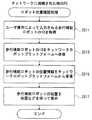
また、上述の各実施例では、図5のステップS9で目的地に到着したと判定されたときに誘導を終了するようにしていた。しかし、他の実施例では、目的地が博物館、店舗などのような建物や屋内を有する施設等であった場合には、当該目的地に到着後に、屋内の誘導処理を実行するようにしてもよい。この機能を実現するための屋内誘導処理の動作の一例が図13に示される。この屋内誘導処理は、図5のステップS9で“YES”と判定された場合に実行される。 In each of the above-described embodiments, the guidance is terminated when it is determined in step S9 in FIG. 5 that the vehicle has arrived at the destination. However, in another embodiment, when the destination is a building or a facility having an indoor structure such as a museum or a store, an indoor guidance process may be executed after arrival at the destination. Good. An example of the operation of the indoor guidance process for realizing this function is shown in FIG. This indoor guidance process is executed when “YES” is determined in step S9 of FIG.
屋内誘導処理を開始すると、ステップS191で、到着した目的地が建物であるか否かを判定する。建物を示すデータは、経路を作成するための地図データ等に予め登録しておくようにしてもよい。あるいは、プラットフォーム82やネットワーク80上の他の装置等に問い合わせするなどしてもよい。ステップS191で“NO”であれば、つまり、目的地の位置に建物が登録されていない場合には、そのままこの屋内誘導処理を終了する。 When the indoor guidance process is started, it is determined in step S191 whether or not the arrival destination is a building. Data indicating a building may be registered in advance in map data or the like for creating a route. Alternatively, inquiries may be made to other devices on the
一方、ステップS191で“YES”であれば、ステップS193で、図5のステップS1と同様にして、プラットフォーム82またはGPS等から現在地を取得する。続いてステップS195で、ネットワーク80から当該建物内の地図情報を取得する。ネットワーク80には、当該建物内の無線LANアクセスポイント84等からアクセスすることができる。たとえば、ネットワーク80上には、建物内の地図情報を提供するサーバが設けられていて、当該サーバに建物の識別情報等を送信することによって当該屋内の検索用経路情報を含む屋内地図情報を取得することができる。あるいは、当該屋内の地図情報を予めHDD54に、記憶媒体やネットワーク80を介して上記サーバ等から取得しておいてもよい。 On the other hand, if “YES” in the step S191, the current location is acquired from the
そして、ステップS197で当該建物内の目的地を設定するための目的地入力処理を実行する。この処理は図6の処理と同様であり、音声入力やタッチパネル操作で目的地を設定できる。なお、この建物内のある場所を目的地に設定する処理は、屋外のある場所や建物などを目的地として設定する図6の目的地入力処理において、当該目的地が建物か否かの判定を行い、当該目的地が建物であると判定される場合に、続けて実行するようにしてもよい。 In step S197, a destination input process for setting a destination in the building is executed. This process is the same as the process of FIG. 6, and the destination can be set by voice input or touch panel operation. Note that the process of setting a certain place in the building as the destination is performed by determining whether or not the destination is a building in the destination input process of FIG. 6 in which a certain place or building outside is set as the destination. If it is determined that the destination is a building, it may be executed continuously.
続いて、ステップS199で、図5のステップS5と同様にして、当該建物内の経路に関する情報を含んだ屋内地図情報に基づいて現在地から目的地までの経路を探索して、屋内の移動経路情報を生成しRAM52記憶する。なお、他の実施例では、ネットワーク80上の他の装置に屋内目的地等の情報を送信して、当該他の装置で作成された屋内の移動経路情報を取得するようにしてもよい。 Subsequently, in step S199, as in step S5 of FIG. 5, a route from the current location to the destination is searched based on indoor map information including information related to the route in the building, and indoor movement route information is obtained. Is generated and stored in the
そして、ステップS201で、移動処理を実行する。この移動処理は、図7の処理と同様である。ただし、屋内だとGPS信号の受信が困難であるので、現在地は、プラットフォーム82または屋内の埋め込み型情報発信機器86等から取得される。ステップS203で目的地に到着したと判定されるまで、移動処理を繰返し実行し、ステップS203で“YES”であればこの屋内誘導処理を終了する。このようにして、屋内でも目的地までユーザを連れて誘導することができる。歩行補助ロボット10が屋内のみで使用される場合には、図5の屋外の誘導処理に代えてこの屋内誘導処理を初めから実行すればよい。 In step S201, a movement process is executed. This movement process is the same as the process of FIG. However, since it is difficult to receive GPS signals indoors, the current location is acquired from the
また、上述の各実施例の歩行補助ロボット10とプラットフォーム82とを含むシステムでは、ネットワーク80に接続されたPC94によって、歩行補助ロボット10や歩行者が現在どこにいるのかを確認することができる。図14には、当該PC94のロボット位置確認処理の動作の一例が示される。 Further, in the system including the walking assist
図14のステップS211では、PC94のユーザ操作によって入力される歩行補助ロボット10のID(識別情報)を取得する。たとえば、PC94の画面にはID入力画面が表示されており、当該画面では、当該PC94のユーザ、すなわち、歩行補助ロボット10と散歩や買い物などの出掛けている歩行者の家族などは、キーボードやマウスなどの入力装置を操作して、当該歩行補助ロボット10のIDを入力することができる。 In step S211 of FIG. 14, the ID (identification information) of the walking assist
次に、ステップS213で、入力された歩行補助ロボット10のIDをプラットフォーム82にネットワーク80を介して送信する。これに応じて、プラットフォーム82は、ロボット位置情報DB82aを検索して、当該IDに対応づけられた位置データを読み出し、PC94に当該位置データをネットワーク80を介して返信する。これに応じて、PC94は、ステップS215で、歩行補助ロボット10の位置データをプラットフォーム82から受信して記憶する。 Next, in
そして、ステップS217で、歩行補助ロボット10の位置を地図などの背景を伴ってPC94のディスプレイに表示する。歩行補助ロボット10の位置は、たとえば当該ロボットを示すアイコンを用いて地図上に表示されてよい。 In step S217, the position of the walking assist
なお、歩行補助ロボット10の現在地とともに歩行者の現在地も一緒に表示するようにしてもよいし、歩行者の現在地のみを表示するようにしてもよい。歩行者の位置は歩行者のIDの入力に応じて表示されてもよい。あるいは、プラットフォーム82で歩行者のIDと歩行補助ロボット10のIDとを対応付けて登録しておくことによって、歩行補助ロボット10のIDのみの入力で、歩行者の位置が表示されるようにしてもよい。また、プラットフォーム82に目的地も登録している場合には、目的地も表示するようにしてもよく、その場合、家族の人等は歩行者の現在地とともに目的地も確認できる。 Note that the current location of the pedestrian may be displayed together with the current location of the walking assist
10 …歩行補助ロボット
12 …車輪
14 …前輪モータ
16 …後輪モータ
22 …距離センサ
24 …座部
30 …つかみ部
34 …スピーカ
36 …操作部(頭部)
38 …LCD
40 …タッチパネル
42 …球体(顔)
44 …カメラ
46 …マイク
48 …触覚センサ
50 …CPU
52 …RAM
54 …HDD
58 …無線通信装置
62 …GPS受信機
66 …タグリーダ
68,70 …サーボコントローラ
72,74 …モータドライバ
76 …首サーボモータ
78 …顔サーボモータ
80 …ネットワーク
82 …ネットワークロボットプラットフォーム
84 …無線LANアクセスポイント
86 …環境埋め込み型情報発信機器
88 …他のロボット
90 …GPS衛星
92 …タグ
94 …PCDESCRIPTION OF
38 ... LCD
40 ...
44 ...
52 ... RAM
54 HDD
58 ...
Claims (8)
Translated fromJapaneseユーザがつかまることが可能に形成されたつかみ部、および
前記移動機構の移動を制御する制御手段を備え、
前記制御手段による移動によって前記つかみ部につかまった前記ユーザを動かす、歩行補助ロボット。Self-propelled movement mechanism,
A grip portion formed so that a user can grip, and a control means for controlling the movement of the moving mechanism,
A walking assist robot that moves the user grasped by the grip portion by movement by the control means.
現在地の位置情報を環境インフラを利用して取得する現在地取得手段をさらに備え、
前記制御手段は、前記現在地取得手段によって取得された前記現在地および前記第1目的地取得手段によって取得された前記目的地に基づいて生成された経路情報によって前記移動を制御する、請求項1記載の歩行補助ロボット。A first destination acquisition means for acquiring a destination based on the user's uttered voice or operation; and a current location acquisition means for acquiring location information of the current location using an environmental infrastructure,
The said control means controls the said movement by the route information produced | generated based on the said present location acquired by the said present location acquisition means and the said destination acquired by the said 1st destination acquisition means. Walking assist robot.
前記制御手段は、前記位置検出手段によって検出された前記位置が所定の範囲内でないとき、当該位置に近付ける位置調整手段を含む、請求項1または2記載の歩行補助ロボット。Further comprising position detecting means for detecting the position of the user;
The walking assist robot according to claim 1, wherein the control unit includes a position adjustment unit that approaches the position when the position detected by the position detection unit is not within a predetermined range.
前記制御手段は、前記推定手段によって推定された前記位置および姿勢の変化に応じて移動速度を調整する第1速度調整手段を含む、請求項1ないし3のいずれかに記載の歩行補助ロボット。Including estimation means for estimating the position and posture of the user based on tactile information acquired by a tactile sensor provided on the body surface and a map stored in the storage means,
4. The walking assist robot according to claim 1, wherein the control unit includes a first speed adjustment unit that adjusts a moving speed according to a change in the position and posture estimated by the estimation unit. 5.
前記制御手段は、前記距離検出手段によって検出された前記距離の変化に応じて移動速度を調整する第2速度調整手段を含む、請求項1ないし4のいずれかに記載の歩行補助ロボット。A distance detecting means for detecting a distance to the user;
5. The walking assist robot according to claim 1, wherein the control unit includes a second speed adjustment unit that adjusts a moving speed according to a change in the distance detected by the distance detection unit.
前記ユーザが座ることが可能に形成された座部をさらに備え、
前記制御手段は、前記位置検出手段によって検出された前記位置が前記座部上である場合に長距離移動をキャンセルし、必要に応じて回転または短距離移動のみを実行する、請求項1ないし5のいずれかに記載の歩行補助ロボット。A walking assist robot including position detecting means for detecting the position of the user;
And further comprising a seat portion formed to allow the user to sit down,
The control means cancels long-distance movement when the position detected by the position detection means is on the seat, and performs only rotation or short-distance movement as necessary. The walking assist robot according to any one of the above.
前記現在地取得手段によって取得された前記現在地の位置情報に付随する情報を出力する情報提供手段をさらに備える、請求項1ないし6のいずれかに記載の歩行補助ロボット。It is a walking assist robot that includes current location acquisition means for acquiring current location information using environmental infrastructure,
The walking assist robot according to any one of claims 1 to 6, further comprising information providing means for outputting information accompanying position information of the current location acquired by the current location acquiring means.
前記制御手段は、前記第1目的地取得手段によって取得された前記目的地に到達後、前記第2目的地取得手段によって取得された前記屋内目的地と前記現在地とに基づいて生成された屋内の経路情報によって前記移動を制御する、請求項2ないし7のいずれかに記載の歩行補助ロボット。When the destination acquired by the first destination acquisition means is a building, the apparatus further comprises second destination acquisition means for acquiring an indoor destination in the building based on a user's speech or operation,
The control means, after reaching the destination acquired by the first destination acquisition means, an indoor generated based on the indoor destination and the current location acquired by the second destination acquisition means The walking assist robot according to claim 2, wherein the movement is controlled based on route information.
Priority Applications (1)
| Application Number | Priority Date | Filing Date | Title |
|---|---|---|---|
| JP2005337184AJP2007139710A (en) | 2005-11-22 | 2005-11-22 | Walking assist robot |
Applications Claiming Priority (1)
| Application Number | Priority Date | Filing Date | Title |
|---|---|---|---|
| JP2005337184AJP2007139710A (en) | 2005-11-22 | 2005-11-22 | Walking assist robot |
Publications (1)
| Publication Number | Publication Date |
|---|---|
| JP2007139710Atrue JP2007139710A (en) | 2007-06-07 |
Family
ID=38202744
Family Applications (1)
| Application Number | Title | Priority Date | Filing Date |
|---|---|---|---|
| JP2005337184AWithdrawnJP2007139710A (en) | 2005-11-22 | 2005-11-22 | Walking assist robot |
Country Status (1)
| Country | Link |
|---|---|
| JP (1) | JP2007139710A (en) |
Cited By (29)
| Publication number | Priority date | Publication date | Assignee | Title |
|---|---|---|---|---|
| JP2012035076A (en)* | 2010-07-30 | 2012-02-23 | Toyota Motor Engineering & Manufacturing North America Inc | Robotic cane device |
| CN102445946A (en)* | 2011-12-02 | 2012-05-09 | 天津工业大学 | Service robot for cafeteria |
| CN102895092A (en)* | 2011-12-13 | 2013-01-30 | 冷春涛 | Multi-sensor integration based three-dimensional environment identifying system for walker aid robot |
| KR101278579B1 (en)* | 2011-05-13 | 2013-06-25 | 주식회사 로보테크 | intelligent walking assistance robot |
| KR101321187B1 (en) | 2013-03-27 | 2013-10-22 | 전북대학교산학협력단 | Walking guide device for a blind man |
| KR101357098B1 (en) | 2011-10-25 | 2014-02-12 | 주식회사 라이프사이언스테크놀로지 | Method for detecting and correcting of bio-signal of walking surport device user |
| CN103759734A (en)* | 2014-01-24 | 2014-04-30 | 成都万先自动化科技有限责任公司 | Service robot assisting crossing of street |
| JP2014511206A (en)* | 2011-01-26 | 2014-05-15 | プスン リサイクリング カンパニィ リミテッド | Road guidance system for the visually impaired |
| JP2014199619A (en)* | 2013-03-29 | 2014-10-23 | 株式会社富士通アドバンストエンジニアリング | Movement control method, movement control program and movement control device |
| JP2015024160A (en)* | 2014-09-30 | 2015-02-05 | 国立大学法人九州工業大学 | Self-supporting walking support device |
| KR101548930B1 (en) | 2013-12-27 | 2015-09-04 | 한국산업기술대학교산학협력단 | Apparatus for improve the linearity of the walking assistant robot to move on lateral slopes |
| KR101555930B1 (en)* | 2013-12-04 | 2015-09-30 | 경남대학교 산학협력단 | Control system of Personal Riding Robot using mobile terminal |
| CN105404302A (en)* | 2015-12-03 | 2016-03-16 | 联想(北京)有限公司 | Mobile device and control method |
| CN107817793A (en)* | 2017-09-28 | 2018-03-20 | 金子旭 | Forward type tracks robot automatically |
| JP2018082755A (en)* | 2016-11-21 | 2018-05-31 | 国立大学法人島根大学 | Walking assistance vehicle and walking assistance system |
| CN108367428A (en)* | 2015-11-16 | 2018-08-03 | 触觉机器人有限责任公司 | Control system for self-moving platforms |
| WO2018143509A1 (en)* | 2017-02-02 | 2018-08-09 | 엘지전자 주식회사 | Moving robot and control method therefor |
| JP2018134334A (en)* | 2017-02-23 | 2018-08-30 | パナソニック株式会社 | Walking support robot and walking support system |
| KR20180106351A (en)* | 2017-03-20 | 2018-10-01 | 경희대학교 산학협력단 | Directional control device for walking assistance |
| CN109015676A (en)* | 2018-08-13 | 2018-12-18 | 范文捷 | A kind of robot for accompanying the walking of old man open air |
| CN109646255A (en)* | 2019-01-22 | 2019-04-19 | 上海交通大学 | Walk help ancillary equipment and its application method |
| TWI661336B (en)* | 2016-10-20 | 2019-06-01 | 鴻海精密工業股份有限公司 | Robot and robot controlling method |
| US20190358821A1 (en)* | 2018-05-25 | 2019-11-28 | Panasonic Corporation | Walking training robot |
| JP2021049098A (en)* | 2019-09-25 | 2021-04-01 | アルパイン株式会社 | Walking assist device |
| JP2021115909A (en)* | 2020-01-23 | 2021-08-10 | トヨタ自動車株式会社 | Mobile |
| CN109862861B (en)* | 2016-09-29 | 2021-09-21 | 科姆派机器人公司 | Auxiliary mobile robot comprising at least one pivoting support system |
| JP2022076648A (en)* | 2020-11-10 | 2022-05-20 | 清水建設株式会社 | Robot handle |
| JP7107616B1 (en) | 2022-01-20 | 2022-07-27 | 直子 近藤 | Guidance guide cane |
| KR20230090552A (en)* | 2021-12-15 | 2023-06-22 | 주식회사 어픽 | System for walking route guiding based on measured data |
- 2005
- 2005-11-22JPJP2005337184Apatent/JP2007139710A/ennot_activeWithdrawn
Cited By (37)
| Publication number | Priority date | Publication date | Assignee | Title |
|---|---|---|---|---|
| JP2012035076A (en)* | 2010-07-30 | 2012-02-23 | Toyota Motor Engineering & Manufacturing North America Inc | Robotic cane device |
| JP2014511206A (en)* | 2011-01-26 | 2014-05-15 | プスン リサイクリング カンパニィ リミテッド | Road guidance system for the visually impaired |
| KR101278579B1 (en)* | 2011-05-13 | 2013-06-25 | 주식회사 로보테크 | intelligent walking assistance robot |
| KR101357098B1 (en) | 2011-10-25 | 2014-02-12 | 주식회사 라이프사이언스테크놀로지 | Method for detecting and correcting of bio-signal of walking surport device user |
| CN102445946A (en)* | 2011-12-02 | 2012-05-09 | 天津工业大学 | Service robot for cafeteria |
| CN102895092A (en)* | 2011-12-13 | 2013-01-30 | 冷春涛 | Multi-sensor integration based three-dimensional environment identifying system for walker aid robot |
| KR101321187B1 (en) | 2013-03-27 | 2013-10-22 | 전북대학교산학협력단 | Walking guide device for a blind man |
| JP2014199619A (en)* | 2013-03-29 | 2014-10-23 | 株式会社富士通アドバンストエンジニアリング | Movement control method, movement control program and movement control device |
| KR101555930B1 (en)* | 2013-12-04 | 2015-09-30 | 경남대학교 산학협력단 | Control system of Personal Riding Robot using mobile terminal |
| KR101548930B1 (en) | 2013-12-27 | 2015-09-04 | 한국산업기술대학교산학협력단 | Apparatus for improve the linearity of the walking assistant robot to move on lateral slopes |
| CN103759734A (en)* | 2014-01-24 | 2014-04-30 | 成都万先自动化科技有限责任公司 | Service robot assisting crossing of street |
| JP2015024160A (en)* | 2014-09-30 | 2015-02-05 | 国立大学法人九州工業大学 | Self-supporting walking support device |
| CN108367428B (en)* | 2015-11-16 | 2021-05-25 | 触觉机器人有限责任公司 | Control system for self-moving platforms |
| CN108367428A (en)* | 2015-11-16 | 2018-08-03 | 触觉机器人有限责任公司 | Control system for self-moving platforms |
| CN105404302A (en)* | 2015-12-03 | 2016-03-16 | 联想(北京)有限公司 | Mobile device and control method |
| CN109862861B (en)* | 2016-09-29 | 2021-09-21 | 科姆派机器人公司 | Auxiliary mobile robot comprising at least one pivoting support system |
| TWI661336B (en)* | 2016-10-20 | 2019-06-01 | 鴻海精密工業股份有限公司 | Robot and robot controlling method |
| JP2018082755A (en)* | 2016-11-21 | 2018-05-31 | 国立大学法人島根大学 | Walking assistance vehicle and walking assistance system |
| KR102055677B1 (en)* | 2017-02-02 | 2019-12-13 | 엘지전자 주식회사 | Mobile robot and method for controlling the same |
| WO2018143509A1 (en)* | 2017-02-02 | 2018-08-09 | 엘지전자 주식회사 | Moving robot and control method therefor |
| KR20180090103A (en)* | 2017-02-02 | 2018-08-10 | 엘지전자 주식회사 | Mobile robot and method for controlling the same |
| US11161250B2 (en) | 2017-02-02 | 2021-11-02 | Lg Electronics Inc. | Moving robot and control method therefor |
| JP2018134334A (en)* | 2017-02-23 | 2018-08-30 | パナソニック株式会社 | Walking support robot and walking support system |
| KR20180106351A (en)* | 2017-03-20 | 2018-10-01 | 경희대학교 산학협력단 | Directional control device for walking assistance |
| KR101963953B1 (en) | 2017-03-20 | 2019-07-31 | 경희대학교 산학협력단 | Directional control device for walking assistance |
| CN107817793A (en)* | 2017-09-28 | 2018-03-20 | 金子旭 | Forward type tracks robot automatically |
| US20190358821A1 (en)* | 2018-05-25 | 2019-11-28 | Panasonic Corporation | Walking training robot |
| CN109015676A (en)* | 2018-08-13 | 2018-12-18 | 范文捷 | A kind of robot for accompanying the walking of old man open air |
| CN109646255A (en)* | 2019-01-22 | 2019-04-19 | 上海交通大学 | Walk help ancillary equipment and its application method |
| JP2021049098A (en)* | 2019-09-25 | 2021-04-01 | アルパイン株式会社 | Walking assist device |
| JP2021115909A (en)* | 2020-01-23 | 2021-08-10 | トヨタ自動車株式会社 | Mobile |
| JP7310620B2 (en) | 2020-01-23 | 2023-07-19 | トヨタ自動車株式会社 | moving body |
| JP2022076648A (en)* | 2020-11-10 | 2022-05-20 | 清水建設株式会社 | Robot handle |
| KR20230090552A (en)* | 2021-12-15 | 2023-06-22 | 주식회사 어픽 | System for walking route guiding based on measured data |
| KR102678130B1 (en)* | 2021-12-15 | 2024-06-26 | 주식회사 어픽 | System for walking route guiding based on measured data |
| JP7107616B1 (en) | 2022-01-20 | 2022-07-27 | 直子 近藤 | Guidance guide cane |
| JP2023105863A (en)* | 2022-01-20 | 2023-08-01 | 直子 近藤 | Guidance guide cane |
Similar Documents
| Publication | Publication Date | Title |
|---|---|---|
| JP2007139710A (en) | Walking assist robot | |
| JP5366048B2 (en) | Information provision system | |
| EP3463244B1 (en) | Guide robot and method and system for operating the same | |
| US9915545B2 (en) | Smart necklace with stereo vision and onboard processing | |
| US9629774B2 (en) | Smart necklace with stereo vision and onboard processing | |
| JP3619380B2 (en) | In-vehicle input / output device | |
| JP5768273B2 (en) | A robot that predicts a pedestrian's trajectory and determines its avoidance behavior | |
| EP2778995A2 (en) | Computer-based method and system for providing active and automatic personal assistance using a robotic device/platform | |
| JPWO2004052597A1 (en) | Robot control apparatus, robot control method, and robot control program | |
| JP6150429B2 (en) | Robot control system, robot, output control program, and output control method | |
| JP2007260822A (en) | Road guidance robot | |
| JP5145569B2 (en) | Object identification method and apparatus | |
| JPWO2005108926A1 (en) | Information processing device, mobile device, and information processing method | |
| WO2015083183A1 (en) | Hand wearable haptic feedback based navigation device | |
| CN202409427U (en) | Portable intelligent electronic blind guide instrument | |
| JP6134895B2 (en) | Robot control system, robot control program, and explanation robot | |
| US11432989B2 (en) | Information processor | |
| CN111108463A (en) | Information processing apparatus, information processing method, and program | |
| KR101715472B1 (en) | Smart walking assistance device for the blind and Smart walking assistance system using the same | |
| KR20180074404A (en) | Robot for airport and method thereof | |
| JP2017170568A (en) | Service providing robot system | |
| JP4839939B2 (en) | Autonomous mobile device | |
| JP5115886B2 (en) | Road guidance robot | |
| JP5194314B2 (en) | Communication system | |
| JP2006263873A (en) | Communication robot system and communication robot |
Legal Events
| Date | Code | Title | Description |
|---|---|---|---|
| A300 | Application deemed to be withdrawn because no request for examination was validly filed | Free format text:JAPANESE INTERMEDIATE CODE: A300 Effective date:20090203 |