JP2007139381A - Instantaneous hot water system - Google Patents
Instantaneous hot water systemDownload PDFInfo
- Publication number
- JP2007139381A JP2007139381AJP2005337360AJP2005337360AJP2007139381AJP 2007139381 AJP2007139381 AJP 2007139381AJP 2005337360 AJP2005337360 AJP 2005337360AJP 2005337360 AJP2005337360 AJP 2005337360AJP 2007139381 AJP2007139381 AJP 2007139381A
- Authority
- JP
- Japan
- Prior art keywords
- hot water
- water supply
- storage tank
- supply pipe
- pipe
- Prior art date
- Legal status (The legal status is an assumption and is not a legal conclusion. Google has not performed a legal analysis and makes no representation as to the accuracy of the status listed.)
- Granted
Links
Images


Landscapes
- Domestic Hot-Water Supply Systems And Details Of Heating Systems (AREA)
- Heat-Pump Type And Storage Water Heaters (AREA)
Abstract
Description
Translated fromJapanese本発明は、即湯システムに係り、特に、給湯器と端末の給湯栓とを接続する給湯配管の途中に湯を溜めておく貯湯タンクを配設させた即湯システムに関する。 The present invention relates to an immediate hot water system, and more particularly, to an immediate hot water system in which a hot water storage tank for storing hot water is provided in the middle of a hot water supply pipe connecting a hot water heater and a hot water tap of a terminal.
給湯個所で給湯栓が開かれると即時に温水を供給することができる即湯システムとして、給湯器に、上水を供給する給水管と給湯個所に通じる出湯管とが接続され、この給水管と出湯管とは、循環ポンプを設けた戻り管で接続されて循環路が形成され、水栓が閉じられて給湯が使用されない時、給湯器及び循環ポンプを作動してこの循環路で所定温度の温水を循環させる循環保温運転を行い、水栓が開かれて給湯が使用された時、給湯個所に即時に温水が供給されるようにする循環方式のものがある。 As an immediate hot water system that can supply hot water immediately when a hot water tap is opened at a hot water supply station, a hot water supply pipe connected to a hot water supply pipe and a hot water supply pipe leading to the hot water supply station are connected to this hot water supply pipe. The hot water pipe is connected by a return pipe provided with a circulation pump to form a circulation path. When the faucet is closed and hot water is not used, the water heater and the circulation pump are operated and a predetermined temperature is set in the circulation path. There is a circulating system in which hot water is circulated so that hot water is immediately supplied to a hot water supply location when the faucet is opened and hot water is used.
また、主給湯器と出湯栓との間に保温加熱体を有する即湯ポットを配設し、該即湯ポットの下部に主給湯器からの給湯配管を直結して出湯初期における給湯配管からの冷水のすべてを即湯ポット内に導き、該冷水と即湯ポット内の湯とを即湯ポット内で混合し即湯ポット上部の出湯口から取り出し出湯栓より流出させる構造の貯湯方式のものもある。 Also, an immediate hot water pot having a heat insulation heating element is disposed between the main hot water heater and the hot water tap, and a hot water supply pipe from the main hot water heater is directly connected to the lower portion of the immediate hot water pot so that the hot water supply pipe from the initial stage of the hot water supply There is also a hot water storage system that guides all the cold water into the immediate hot water pot, mixes the cold water and the hot water in the immediate hot water pot in the immediate hot water pot, takes it out of the hot water outlet at the top of the immediate hot water pot, and flows it out of the hot water tap is there.
後者のタイプにあっては、出湯初期において下部から流入する冷水で即湯ポット内に貯留する高温湯が押し上げられ、上部の出湯口からは高温湯だけが取り出されそのまま出湯口から流出するという問題があり、これを解消すべく、主給湯器から即湯ポットへの給湯配管から分岐せるバイパス路を即湯ポットの出湯口に臨ませ、出湯初期における給湯配管からの冷水をバイパス側と即湯ポット側とに分岐し即湯ポットの湯とバイパス路からの冷水を出湯口で混合して出湯せしめる即湯システムも提案されている(例えば、特許文献1参照。)。
しかしながら、循環方式のものでは、循環ポンプ等の追加部品がコストアップの要因となる。また、貯湯方式のものでは、電気ヒータ等の部品代がかかる外、水を加熱する際に生じる膨張水と圧力を逃がして即湯ポットが水圧によって破損するのを防止するために減圧弁等の安全装置も必要となって、高価なものになってしまうという問題がある。 However, in the circulation type, additional parts such as a circulation pump cause a cost increase. Moreover, in the case of the hot water storage system, parts such as an electric heater are not charged, but a pressure reducing valve or the like is used to prevent the instant hot water pot from being damaged by water pressure by releasing the expansion water and pressure generated when heating the water. There is a problem that a safety device is also required, which makes it expensive.
さらに、これら初期費用に加えて、循環ポンプや電気ヒータを作動させ続けることは電気代等の維持費を必要とするばかりか、地球温暖化対策等の環境保全の観点からも好ましくない。 Further, in addition to these initial costs, continuing to operate the circulation pump and the electric heater not only requires maintenance costs such as electricity costs, but is also not preferable from the viewpoint of environmental conservation such as measures against global warming.
本発明は、上述した事情を考慮してなされたもので、シンプルな構造で安価に製造でき、且つ保温用の電気代等がかからない即湯システムを提供することを目的とする。 The present invention has been made in view of the above-described circumstances, and an object of the present invention is to provide an instant hot water system that can be manufactured at a low cost with a simple structure and does not require an electricity bill for heat insulation.
本発明に係る即湯システムは、上述した課題を解決するために、請求項1に記載したように、給湯器と端末の出湯栓とを接続する給湯配管の途中に配設される即湯システムにおいて、断熱性を有する構造に形成され下部に上記給湯配管の上流側に直結された入湯口と、上部に上記給湯配管の下流側に接続された出湯口とが設けられた貯湯タンクを配設し、上記入湯口から出湯初期における上記給湯配管からの冷水のすべてを上記貯湯タンク内に導き、該冷水と上記貯湯タンク内の湯とを該貯湯タンク内で混合し上記出湯口から取り出し上記出湯栓より流出させるものである。 In order to solve the above-described problem, an instant hot water system according to the present invention is an instant hot water system disposed in the middle of a hot water supply pipe connecting a hot water heater and a hot water tap of a terminal as described in claim 1. A hot water storage tank having a heat insulating structure and having a hot water inlet connected directly to the upstream side of the hot water supply pipe at the lower part and a hot water outlet connected to the downstream side of the hot water supply pipe at the upper part. Then, all the cold water from the hot water supply pipe in the initial stage of hot water discharge from the hot water inlet is introduced into the hot water storage tank, and the cold water and hot water in the hot water storage tank are mixed in the hot water storage tank and taken out from the hot water outlet. It flows out from the stopper.
また、上述した課題を解決するために、請求項2に係る即湯システムは、給湯器と端末の出湯栓とを接続する給湯配管の途中に配設される即湯システムにおいて、断熱性を有する構造に形成され上部に上記給湯配管に接続される上部給湯口と、下部に下部給湯口とが設けられた貯湯タンクと、該給湯配管の上記貯湯タンクより上流側において上記給湯配管が分岐配管され上記貯湯タンクの上記下部給湯口へ接続されるバイパス本管と、該バイパス本管と上記給湯配管との分岐部において上記給湯器から供給される湯温を感知し、該湯温が所定の温度以下の場合は湯を上記バイパス本管へと送出し、上記湯温が所定の温度以上の場合は湯の送出先を上記給湯配管へと切替える流路切替手段と、上記給湯配管の上記貯湯タンクより下流側において上記バイパス本管及び上記貯等タンク下部のいずれかから分岐配管され上記貯湯タンクの下流側において上記給湯配管に接続されるバイパス支管とを備えるものである。 Moreover, in order to solve the above-mentioned problem, the immediate hot water system according to
そして、前記即湯システムは、好適には、請求項3に記載したように、前記給湯配管の前記上部給湯口との分岐部と、前記バイパス支管との接続部との間に水圧調整手段を備えることが望ましい。 And as for the said instant hot water system, Preferably, as described in
本発明に係る即湯システムによれば、シンプルな構造で安価に製造でき、且つ保温用の電気代等がかからない即湯システムが得られる効果がある。 According to the instant hot water system of the present invention, there is an effect that an instant hot water system that can be manufactured at a low cost with a simple structure and that does not require an electricity bill for heat insulation or the like is obtained.
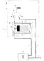
本発明に係る即湯システムの第1の実施形態について、添付図面を参照して説明する。図1は、本実施形態に係る即湯システム2を備える給湯装置1の全体的な概要を模式的に示す構成図である。 A first embodiment of an instant hot water system according to the present invention will be described with reference to the accompanying drawings. FIG. 1 is a configuration diagram schematically illustrating an overall outline of a hot water supply apparatus 1 including an immediate
浴室3が設けられた建物内に引き込まれた建築給水配管5は、同図に示すように、浴室3の外部において分岐し、一方は給湯器4に、他方は浴室3内のサーモスタット付水栓9の給水接続口9aに接続される。また、給湯器4からは、給湯配管7が延設され、その終端はサーモスタット付水栓9の給湯接続口9bに接続される。 As shown in the figure, the building water supply pipe 5 drawn into the building in which the
給湯配管7の途中には、本実施形態に係る即湯システム2を構成する貯湯タンク8が設けられ、給湯配管7の給湯器4側は、貯等タンク8の底部に設けられた入湯口8aに接続され、給湯配管7のサーモスタット付水栓9側は、貯等タンク8の頂部に設けられた出湯口8bに接続される。 A hot
この貯湯タンク8は、ポリプロピレン、ポリエチレン、ポリスチロール等のプラスティック系の材料を発泡成形させた断熱材を、溶着等により例えば円筒状或いは中空角柱状のステンレス製のタンク等に施し、貯湯タンク8内に溜められた湯は容易には冷めないようになっている。なお、本実施形態に係る貯湯タンク8は、本発明の即湯システム2を構成する。 In this hot
サーモスタット付水栓9は、内部に設けられたサーモスタットを介して、給水接続口9aから流入する水と給湯接続口9bから流入する湯とを良好に混合して、適温の温水とすることができるものである。このサーモスタット付水栓9からは、シャワー96(図2参照。)を分岐させることもできる。なお、本実施形態に係るサーモスタット付水栓9は、本発明の出湯栓を構成する。 The water tap 9 with a thermostat can mix hot water flowing in from the water
給湯装置1を長時間使用しないでいると、給湯配管7内に残った残存水の水温は低下するが、貯湯タンク8内に貯留された湯の温度は、貯湯タンク8が断熱材から形成されていることから大きく低下することはない。 If the hot water supply device 1 is not used for a long time, the temperature of the remaining water remaining in the hot
この状態で、給湯器4を点火すると、給湯器4から送出される湯によって給湯配管7内の残存水は押しやられ、入湯口8aから貯湯タンク8内に流入する。すると、貯湯タンク8内の湯は押し上げられて出湯口8bから給湯配管7へと押し上げられ、給湯接続口9bからサーモスタット付水栓9へと流入し、ここで給水配管6からの水と混合して、適温の温水となってカラン9cから取り出される。したがって、出湯初期においては、出湯口8bと給湯接続口9bとを接続する給湯配管7内に残っていた残存水がサーモスタット付水栓9内へと送られるため、この間はカラン9cからは冷水が吐出されるものの、短時間で適温の温水を得ることができる。 When the
給湯器4と入湯口8aとの間の給湯配管7内の残存水は貯湯タンク8内の湯よりも比重が大きいので、貯湯タンク8内に入っても、貯湯タンク8底部に沈殿して、出湯口8bから流出することはなく、よって、サーモスタット付水栓9にそのまま送られることもない。 Since the remaining water in the hot
続いて、給湯器4からの湯が貯湯タンク8内に流入すると、この湯は貯湯タンク8底部に沈殿する残存水より比重が小さいことから両者は混和して、水温も平均化される。そして、この状態でサーモスタット付水栓9内に流入するので、カラン9cから冷水が吐出されることはない。 Subsequently, when hot water from the
図2に、上述した即湯システム2の浴室内における配置を示す。浴室3内に、洗い場91の一端には浴槽92が設置され、その洗い場91側の側面はバスエプロン93により閉塞される。洗い場91側には、洗い場カウンタ94を介して洗い場水栓95が取設される。この洗い場水栓95からは、シャワー96が分岐する。 In FIG. 2, arrangement | positioning in the bathroom of the instant
このように形成された浴室3内において、即湯システム2は、湯が給湯配管7を通過中に熱を失い湯温が低下することを抑えるために、貯湯タンク8の出湯口8bとサーモスタット付水栓9の給湯接続口9bとを接続する給湯配管7の長さをできるだけ短くするように、サーモスタット付水栓9に近接して洗い場カウンタ94内に収納することが望ましい。洗い場カウンタ94を有さない浴室では、バスエプロン93の裏面等に設置される。 In the
このように、即湯システム2は、電気ヒータ等を必要とせず、安価な断熱材で製造され、また、加熱処理を加えないので、減圧弁等の安全装置も不必要となり、安全且つさらに安価となる。 Thus, the instant
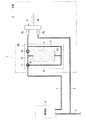
次に、本発明に係る即湯システムの第2の実施形態について、添付図面を参照して説明する。図3は、本実施形態に係る即湯システム2Aを備える給湯装置1の全体的な概要を模式的に示す構成図である。 Next, a second embodiment of the instant hot water system according to the present invention will be described with reference to the accompanying drawings. FIG. 3 is a configuration diagram schematically illustrating an overall outline of the hot water supply apparatus 1 including the immediate
本実施の形態に係る即湯システム2Aは、同図に示すように、貯湯タンク8に加え、給湯支管10、バイパス本管11、サーモスタット付切替弁12及びバイパス支管13を備え、給湯配管7に直接接続されるのではなく、これらバイパス本管10やバイパス支管12等を介して接続される点で、第1の実施形態におけるものと基本的に相違し、他の構成は第1の実施形態と実質的に同じであり、同じ符号を付して説明を省略する。 The
給湯支管10は、給湯配管7から分岐配管され、終端は貯湯タンク8の上部に設けられた上部給湯口8dに接続される。給湯支管10への流量と下流側の給湯配管7への流量との比率(例えば8:2)は、それぞれの管径の比によって、或いは流量調整弁を設けることによって調整される。 The hot water
バイパス本管11は、給湯配管7から給湯支管10が分岐する分岐点より上流側において給湯配管7から分岐配管され、終端は貯湯タンク8の下部に設けられた下部給湯口8dに接続される。 The bypass
このバイパス本管11が給湯配管7から分岐する分岐点には、サーモスタット付切替弁12が取り付けられる。サーモスタット付切替弁12は、内部にサーモスタットを有し、給湯器4側から送られる湯の温度が所定の温度(例えば50℃程度)より低ければこの湯をバイパス本管11側へ送出し、所定温度より高くなればこれを給湯配管7側へ送出するように流路を切り替える機能を備える。 A switching
本実施形態におけるサーモスタット付切替弁12は、本発明における流路切替手段を構成する。なお、流路切替手段としては、例えば、温度センサが感知した水温に従って流路を自動的に切り替える三方電磁弁等であってもよい。 The switching
バイパス本管11の下流近傍からは、バイパス支管13が分岐配管され、終端は給湯配管7から給湯支管10が分岐する分岐点より下流側において給湯配管7に接続される。バイパス支管13の流量は、バイパス本管11のそれよりも小さくなるよう設定され、それは、通常それぞれの管径の比によって調整されるが、流量調整弁を設けることによって調整してもよい。 A
本実施の形態に係る即湯システム2Aは上記のように構成されており、以下その動作について説明する。なお、以下の各図において、各管及び貯湯タンク8内の塗りつぶしは湯を、ハッチングは水をそれぞれ示すものとする。 The immediate
本給湯装置1を初めて使用する場合や、長期に亘って使用しなかった後に使用する場合は、図4に示すように、各管内及び貯湯タンク8内の残存水は冷め切っている。その状態で給湯器4を点火すると、出湯初期においてはサーモスタット付切替弁12を水が通過するので、この水はサーモスタットの働きによりバイパス本管11側へと導通され、その後、主に貯湯タンク8から給湯支管11を経由して、また一部はバイパス支管13を経由して給湯配管7へと戻され、給水配管6からの水と混合されてサーモスタット付水栓9から吐出される。この水は、従来通り暫くの間冷たいままである。 When the hot water supply device 1 is used for the first time or after it has not been used for a long time, the remaining water in each pipe and the hot
給湯器4の使用を継続すると、図5に示すように、給湯器4で加熱された湯がサーモスタット付切替弁12に到達し、この湯の送出先は、給湯配管7側へと切り替わる。 If the use of the
そして、給湯配管7を通過する湯の一部は、給湯支管10へと分流し、貯湯タンク8内に溜められる。この湯は、貯湯タンク8内の残存水より比重が小さいので上澄みとして貯留され、貯湯タンク8底部にある残存水は、下部給湯口8dからバイパス本管11、バイパス支管13を経て、給湯配管7へと送られる。 A part of the hot water passing through the hot
給湯配管7に送られた残存水及びサーモスタット付切替弁12から直送された湯は、サーモスタット付水栓9に至り、給水配管6からの水と混合されて、適温の湯となって吐出される。この時点において、給湯装置1の本来の機能が発揮され始める。 Residual water sent to the hot
なおも給湯器4の使用を継続すると、図6に示すように、貯湯タンク8内における給湯器4からの湯の量は増加し、遂には貯湯タンク8は給湯器4からの湯で満タンとなって、下部給湯口8dからバイパス本管11、バイパス支管13を経て、給湯配管7へと送られる。この時点でサーモスタット付水栓9の給湯接続口9bに送出される湯は、全て給湯器4からの湯で占められ、給湯装置1の本来の機能が完全に発揮される。 If the use of the
このように貯湯タンク8内は高温の湯で満タンになっているので、ここで給湯器4の使用を終了しても、貯湯タンクの断熱効果により、貯湯タンク8内の湯温は高いまま、次に使用する人のための準備ができた状態に保たれる。 Since the hot
次の人が使用するときには、図7に示すように、給湯配管7内の水温は下がっているので、給湯器4からの湯に押された給湯配管7内の水は、サーモスタット付切替弁12によってバイパス本管側へと送出される。すると、比重の大きいこの水は、貯湯タンク8の下部給湯口8dから貯湯タンク8内の湯を押し上げ、湯は、上部給湯口8cから給湯支管10、給湯配管7を経由して、サーモスタット付水栓9に至り、給水配管6からの水と混合されて、適温の湯となって吐出される。 When the next person uses, as shown in FIG. 7, the water temperature in the hot
このまま使用を継続すると、図8に示すように、やがて給湯器4からの湯がサーモスタット付切替弁12に至り、流路がバイパス本管11から給湯配管7側へと切り替えられ、給湯配管7を通過する湯の一部は、給湯支管10へと分流し、上部給湯口8cから貯湯タンク8内に溜められる。この湯は、バイパス本管11から貯湯タンク8内に送られた冷水より比重が小さいので上澄みとして貯留され、貯湯タンク8底部にある冷水は、下部給湯口8dからバイパス本管11、バイパス支管13を経て、給湯配管7へと送られる。 If the use is continued as shown in FIG. 8, the hot water from the
給湯配管7に送られた残存水及びサーモスタット付切替弁12から直送された湯は、サーモスタット付水栓9に至り、給水配管6からの水と混合されて、適温の湯となって吐出される。これは、図5に示した最初に使用する場合と同様である。 Residual water sent to the hot
なおも給湯器4の使用を継続すると、図8に示すように、貯湯タンク8内における給湯器4からの湯の量は増加し、遂には貯湯タンク8は給湯器4からの湯で満タンとなって、下部給湯口8dからバイパス本管11、バイパス支管13を経て、給湯配管7へと送られる。この時点でサーモスタット付水栓9の給湯接続口9bに送出される湯は、全て給湯器4からの湯で占められる。これは、図6に示した最初に使用する場合と同様である。 If the use of the
このように、本実施形態に係る即湯システム2Aによれば、電気ヒータ等を必要とせず、安価な断熱材で製造されながら、2回目以降に使用する場合は、最初から適温の湯を得ることが可能となる。 As described above, according to the instant
また、第1の実施形態に係る即湯システム2においては、出湯初期における給湯配管7からの冷水のすべてが貯湯タンク8内の下部に直接流入するため出湯初期においては下流から流入する冷水で貯湯タンク8内に貯留する高温湯が押し上げられる状態となって上部の出湯口8aからは高温湯だけが取り出され、貯湯タンク8内の高温湯がそのままサーモスタット付水栓9から流出し、その後これらは混合されて湯温は低下するが、高温湯はその殆どが先に流出してしまうために混合湯の大部分が冷水となってその湯温は急速に低下し出湯温は急激に低くなり、その後、給湯器4からの湯のみに移行すると再び湯温は徐々に上昇して、出湯初期に高温湯が出湯されて火傷の危険があり、貯湯タンク8内の湯の消費が激しく、また、出湯時の貯湯タンク8内の温度低下を給湯使用下限の温度(例えば30℃)を下回らないようにするのが好ましいが、出湯初期における温度変化が激しいために特別の混合弁等を設けて調整する必要が生じる虞があるが、本実施形態に係る即湯システム2Aによれば、そのような虞はない。 Further, in the immediate
続いて、本実施形態に係る即湯システムの変形例について、図10を参照して説明する。 Next, a modification of the instant hot water system according to the present embodiment will be described with reference to FIG.
本変形例に係る即湯システム2Bは、同図に示すように、給湯配管7と給湯支管10との分岐部と、バイパス支管13と給湯配管7との接続部との間に水圧調整手段としての流量調整弁14を備える点で、第2の実施形態におけるものと基本的に相違し、他の構成は第2の実施形態と実質的に同じであり、同じ符号を付して説明を省略する。 As shown in the figure, the instant
第2の実施形態に係る即湯システム2Aは、給湯配管7に接続される給湯支管10、バイパス本管11及びバイパス支管13を備え、多数の配管分岐部を有するため管内の湯が上述したように上手く流れず、また、貯湯タンク7内の湯水がスムーズに入れ替わらない虞がある。そこで、流量調整弁14を設けることにより、斯かる不具合発生の可能性を低減させようとするものである。したがって、この目的を達成できるものであれば、水圧調整手段として圧力調整弁を用いてもよい。 The instant
図11に示すのは、第2の実施形態に係る即湯システムの他の変形例である。この変形例に係る即湯システム2Cは、基本的構成は上述した変形例と同じであるが、バイパス本管11を貯湯タンク8内に収納した構成となっている。 FIG. 11 shows another modification of the quick water system according to the second embodiment. The immediate
また、貯湯タンク8内の下部給湯口8d近傍には、流入する水の勢いにより流入水と貯湯タンク8内の湯とが混合することを防止するために攪拌防止傘15が設けられる。 Further, in the vicinity of the lower hot
これらにより、即湯システムをコンパクトに形成することができ、さらに使い勝手が向上する。 By these, an instant hot water system can be formed compactly and the usability improves further.
以上に説明した実施態様は説明のためのものであり、本発明の範囲を制限するものではない。従って、当業者であればこれらの各要素もしくは全要素をこれと均等なものによって置換した実施態様を採用することが可能であるが、これらの実施態様も本発明の範囲に含まれる。 The embodiments described above are for illustrative purposes and do not limit the scope of the invention. Accordingly, those skilled in the art can employ embodiments in which each or all of these elements are replaced by equivalents thereof, and these embodiments are also included in the scope of the present invention.
1 給湯装置
2,2A,2B 即湯システム
3 浴室
4 給湯器
5 建築給水配管
6 給水配管
7 給湯配管
8 貯湯タンク
8a 入湯口
8b 出湯口
8c 上部給湯口
8d 下部給湯口
9 サーモスタット付水栓
9a 給水接続口
9b 給湯接続口
10 給湯支管
11 バイパス本管
12 サーモスタット付切替弁
13 バイパス支管
14 流量調整弁
15 攪拌防止傘DESCRIPTION OF SYMBOLS 1 Hot
Claims (3)
Translated fromJapanese断熱性を有する構造に形成され下部に上記給湯配管の上流側に直結された入湯口と、上部に上記給湯配管の下流側に接続された出湯口とが設けられた貯湯タンクを配設し、
上記入湯口から出湯初期における上記給湯配管からの冷水のすべてを上記貯湯タンク内に導き、該冷水と上記貯湯タンク内の湯とを該貯湯タンク内で混合し上記出湯口から取り出し上記出湯栓より流出させることを特徴とする即湯システム。In the immediate hot water system that is arranged in the middle of the hot water supply pipe connecting the hot water heater and the outlet tap of the terminal,
A hot water storage tank provided with a hot water inlet connected to the upstream side of the hot water supply pipe at the lower part and a hot water outlet connected to the downstream side of the hot water supply pipe at the upper part is arranged in a structure having a heat insulating property,
All the cold water from the hot water supply pipe in the initial stage of the hot water discharge from the hot water inlet is introduced into the hot water storage tank, the cold water and the hot water in the hot water storage tank are mixed in the hot water storage tank, taken out from the hot water outlet and taken out from the hot water tap. Instant hot water system characterized by drainage.
断熱性を有する構造に形成され上部に上記給湯配管に接続される上部給湯口と、下部に下部給湯口とが設けられた貯湯タンクと、
該給湯配管の上記貯湯タンクより上流側において上記給湯配管が分岐配管され上記貯湯タンクの上記下部給湯口へ接続されるバイパス本管と、
該バイパス本管と上記給湯配管との分岐部において上記給湯器から供給される湯温を感知し、該湯温が所定の温度以下の場合は湯を上記バイパス本管へと送出し、上記湯温が所定の温度以上の場合は湯の送出先を上記給湯配管へと切替える流路切替手段と、
上記給湯配管の上記貯湯タンクより下流側において上記バイパス本管及び上記貯等タンク下部のいずれかから分岐配管され上記貯湯タンクの下流側において上記給湯配管に接続されるバイパス支管と、
を備えることを特徴とする即湯システム。In the immediate hot water system that is arranged in the middle of the hot water supply pipe connecting the hot water heater and the outlet tap of the terminal,
A hot water storage tank formed in a heat insulating structure and connected to the hot water supply pipe at the upper part, and a hot water storage tank provided with a lower hot water supply part at the lower part;
A bypass main pipe which is branched from the hot water supply pipe upstream of the hot water storage tank and connected to the lower hot water supply port of the hot water storage tank;
The temperature of the hot water supplied from the water heater is sensed at a branch portion between the bypass main pipe and the hot water supply pipe, and when the hot water temperature is equal to or lower than a predetermined temperature, the hot water is sent to the bypass main pipe. A flow path switching means for switching the hot water delivery destination to the hot water supply pipe when the temperature is equal to or higher than a predetermined temperature;
A bypass branch pipe that is branched from either the bypass main pipe or the lower part of the storage tank at the downstream side of the hot water storage tank of the hot water supply pipe and is connected to the hot water supply pipe at the downstream side of the hot water storage tank;
An instant hot water system characterized by comprising
Priority Applications (1)
| Application Number | Priority Date | Filing Date | Title |
|---|---|---|---|
| JP2005337360AJP4747799B2 (en) | 2005-11-22 | 2005-11-22 | Instant hot water system |
Applications Claiming Priority (1)
| Application Number | Priority Date | Filing Date | Title |
|---|---|---|---|
| JP2005337360AJP4747799B2 (en) | 2005-11-22 | 2005-11-22 | Instant hot water system |
Related Child Applications (3)
| Application Number | Title | Priority Date | Filing Date |
|---|---|---|---|
| JP2008316825ADivisionJP4771299B2 (en) | 2008-12-12 | 2008-12-12 | Instant hot water system |
| JP2008316966ADivisionJP5105315B2 (en) | 2008-12-12 | 2008-12-12 | Instant hot water system |
| JP2008316826ADivisionJP4873380B2 (en) | 2008-12-12 | 2008-12-12 | Instant hot water system |
Publications (2)
| Publication Number | Publication Date |
|---|---|
| JP2007139381Atrue JP2007139381A (en) | 2007-06-07 |
| JP4747799B2 JP4747799B2 (en) | 2011-08-17 |
Family
ID=38202465
Family Applications (1)
| Application Number | Title | Priority Date | Filing Date |
|---|---|---|---|
| JP2005337360AExpired - Fee RelatedJP4747799B2 (en) | 2005-11-22 | 2005-11-22 | Instant hot water system |
Country Status (1)
| Country | Link |
|---|---|
| JP (1) | JP4747799B2 (en) |
Cited By (7)
| Publication number | Priority date | Publication date | Assignee | Title |
|---|---|---|---|---|
| JP2009052885A (en)* | 2008-12-12 | 2009-03-12 | Toto Ltd | Instantaneous hot water system |
| JP2010286189A (en)* | 2009-06-12 | 2010-12-24 | Toto Ltd | Instantaneous hot water supply system |
| JP2011075161A (en)* | 2009-09-29 | 2011-04-14 | Toto Ltd | Instantaneous hot water supply system |
| JP2011075160A (en)* | 2009-09-29 | 2011-04-14 | Toto Ltd | Instantaneous hot water system |
| JP2011075159A (en)* | 2009-09-29 | 2011-04-14 | Toto Ltd | Instantaneous hot water system |
| JP2014016117A (en)* | 2012-07-10 | 2014-01-30 | Osaka Gas Co Ltd | Instantaneous hot water supply system |
| CN112263143A (en)* | 2020-10-23 | 2021-01-26 | 佛山市顺德区美的饮水机制造有限公司 | Method and device for instant heating type drinking equipment, storage medium and processor |
Citations (5)
| Publication number | Priority date | Publication date | Assignee | Title |
|---|---|---|---|---|
| JPS61276655A (en)* | 1985-05-30 | 1986-12-06 | Matsushita Electric Ind Co Ltd | Hot water supplying device |
| JPS62108935A (en)* | 1985-11-08 | 1987-05-20 | Matsushita Electric Ind Co Ltd | water heater |
| JPH01266463A (en)* | 1988-04-18 | 1989-10-24 | Paloma Ind Ltd | Instant hot water device |
| JPH02115628A (en)* | 1988-10-26 | 1990-04-27 | Matsushita Electric Ind Co Ltd | Instant hot water piping unit |
| JPH03129826A (en)* | 1989-10-16 | 1991-06-03 | Nec Kyushu Ltd | Resist film formation device |
- 2005
- 2005-11-22JPJP2005337360Apatent/JP4747799B2/ennot_activeExpired - Fee Related
Patent Citations (5)
| Publication number | Priority date | Publication date | Assignee | Title |
|---|---|---|---|---|
| JPS61276655A (en)* | 1985-05-30 | 1986-12-06 | Matsushita Electric Ind Co Ltd | Hot water supplying device |
| JPS62108935A (en)* | 1985-11-08 | 1987-05-20 | Matsushita Electric Ind Co Ltd | water heater |
| JPH01266463A (en)* | 1988-04-18 | 1989-10-24 | Paloma Ind Ltd | Instant hot water device |
| JPH02115628A (en)* | 1988-10-26 | 1990-04-27 | Matsushita Electric Ind Co Ltd | Instant hot water piping unit |
| JPH03129826A (en)* | 1989-10-16 | 1991-06-03 | Nec Kyushu Ltd | Resist film formation device |
Cited By (8)
| Publication number | Priority date | Publication date | Assignee | Title |
|---|---|---|---|---|
| JP2009052885A (en)* | 2008-12-12 | 2009-03-12 | Toto Ltd | Instantaneous hot water system |
| JP2010286189A (en)* | 2009-06-12 | 2010-12-24 | Toto Ltd | Instantaneous hot water supply system |
| JP2011075161A (en)* | 2009-09-29 | 2011-04-14 | Toto Ltd | Instantaneous hot water supply system |
| JP2011075160A (en)* | 2009-09-29 | 2011-04-14 | Toto Ltd | Instantaneous hot water system |
| JP2011075159A (en)* | 2009-09-29 | 2011-04-14 | Toto Ltd | Instantaneous hot water system |
| JP2014016117A (en)* | 2012-07-10 | 2014-01-30 | Osaka Gas Co Ltd | Instantaneous hot water supply system |
| CN112263143A (en)* | 2020-10-23 | 2021-01-26 | 佛山市顺德区美的饮水机制造有限公司 | Method and device for instant heating type drinking equipment, storage medium and processor |
| CN112263143B (en)* | 2020-10-23 | 2022-06-14 | 佛山市顺德区美的饮水机制造有限公司 | Method and device for instant heating type drinking equipment, storage medium and processor |
Also Published As
| Publication number | Publication date |
|---|---|
| JP4747799B2 (en) | 2011-08-17 |
Similar Documents
| Publication | Publication Date | Title |
|---|---|---|
| JP5500866B2 (en) | Hot water system | |
| CN101063553B (en) | Heat pump hot water supply device and hot water supply method thereof | |
| TWI414732B (en) | Device for dispensing water with variable temperatures | |
| JP5206798B2 (en) | Sanitary hot water production equipment | |
| JP5403490B2 (en) | Instant water heater | |
| JP2008138925A (en) | Heat pump water heater | |
| JP5938209B2 (en) | Hot water storage system | |
| JP4747799B2 (en) | Instant hot water system | |
| JP2009270751A (en) | Hot water supply device | |
| JP5105315B2 (en) | Instant hot water system | |
| JP4771299B2 (en) | Instant hot water system | |
| JP4873380B2 (en) | Instant hot water system | |
| JP2004257575A (en) | Hot water supply device for storage type water heater | |
| JP6286312B2 (en) | Hot water storage system | |
| JP3848865B2 (en) | Bath water heater | |
| JP2015031456A (en) | Hot water supply device | |
| JP5938208B2 (en) | Hot water storage system | |
| JP2002122353A (en) | Hot water reserving water heater | |
| JP2005315523A (en) | Hot-water supply device | |
| JP5050641B2 (en) | Hot water storage water heater | |
| JP2004125228A (en) | Water heater | |
| JP3704568B2 (en) | Hot water heater with high temperature difference hot water function | |
| JP7243525B2 (en) | Storage hot water heater | |
| JP3865231B2 (en) | Water heater | |
| JP5254894B2 (en) | Bath equipment |
Legal Events
| Date | Code | Title | Description |
|---|---|---|---|
| A621 | Written request for application examination | Free format text:JAPANESE INTERMEDIATE CODE: A621 Effective date:20080619 | |
| A977 | Report on retrieval | Free format text:JAPANESE INTERMEDIATE CODE: A971007 Effective date:20100827 | |
| A131 | Notification of reasons for refusal | Free format text:JAPANESE INTERMEDIATE CODE: A131 Effective date:20101005 | |
| A521 | Written amendment | Free format text:JAPANESE INTERMEDIATE CODE: A523 Effective date:20101105 | |
| TRDD | Decision of grant or rejection written | ||
| A01 | Written decision to grant a patent or to grant a registration (utility model) | Free format text:JAPANESE INTERMEDIATE CODE: A01 Effective date:20110419 | |
| A61 | First payment of annual fees (during grant procedure) | Free format text:JAPANESE INTERMEDIATE CODE: A61 Effective date:20110502 | |
| R150 | Certificate of patent or registration of utility model | Ref document number:4747799 Country of ref document:JP Free format text:JAPANESE INTERMEDIATE CODE: R150 Free format text:JAPANESE INTERMEDIATE CODE: R150 | |
| FPAY | Renewal fee payment (event date is renewal date of database) | Free format text:PAYMENT UNTIL: 20140527 Year of fee payment:3 | |
| LAPS | Cancellation because of no payment of annual fees |