JP2007136775A - Exposed image inputting device, and printer - Google Patents
Exposed image inputting device, and printerDownload PDFInfo
- Publication number
- JP2007136775A JP2007136775AJP2005331461AJP2005331461AJP2007136775AJP 2007136775 AJP2007136775 AJP 2007136775AJP 2005331461 AJP2005331461 AJP 2005331461AJP 2005331461 AJP2005331461 AJP 2005331461AJP 2007136775 AJP2007136775 AJP 2007136775A
- Authority
- JP
- Japan
- Prior art keywords
- unit
- image
- exposure
- scanning direction
- image data
- Prior art date
- Legal status (The legal status is an assumption and is not a legal conclusion. Google has not performed a legal analysis and makes no representation as to the accuracy of the status listed.)
- Pending
Links
- 238000012937correctionMethods0.000claimsabstractdescription56
- 239000003086colorantSubstances0.000claimsdescription3
- 238000003854Surface PrintMethods0.000abstractdescription5
- 230000006870functionEffects0.000description23
- 238000012546transferMethods0.000description13
- 238000000034methodMethods0.000description10
- 238000003860storageMethods0.000description10
- 238000010586diagramMethods0.000description8
- 230000002093peripheral effectEffects0.000description8
- 239000011521glassSubstances0.000description7
- 238000012545processingMethods0.000description6
- 230000003287optical effectEffects0.000description4
- 238000004140cleaningMethods0.000description3
- 239000000758substrateSubstances0.000description3
- 238000011144upstream manufacturingMethods0.000description3
- 230000005540biological transmissionEffects0.000description2
- 238000007599dischargingMethods0.000description2
- 238000006073displacement reactionMethods0.000description2
- 238000009434installationMethods0.000description2
- 238000004519manufacturing processMethods0.000description2
- 238000012360testing methodMethods0.000description2
- 230000015572biosynthetic processEffects0.000description1
- 238000009792diffusion processMethods0.000description1
- 238000003384imaging methodMethods0.000description1
- 239000004973liquid crystal related substanceSubstances0.000description1
- 238000012423maintenanceMethods0.000description1
- 238000005259measurementMethods0.000description1
Images


Classifications
- H—ELECTRICITY
- H04—ELECTRIC COMMUNICATION TECHNIQUE
- H04N—PICTORIAL COMMUNICATION, e.g. TELEVISION
- H04N1/00—Scanning, transmission or reproduction of documents or the like, e.g. facsimile transmission; Details thereof
- H04N1/40—Picture signal circuits
- H04N1/401—Compensating positionally unequal response of the pick-up or reproducing head
- H04N1/4015—Compensating positionally unequal response of the pick-up or reproducing head of the reproducing head
- H—ELECTRICITY
- H04—ELECTRIC COMMUNICATION TECHNIQUE
- H04N—PICTORIAL COMMUNICATION, e.g. TELEVISION
- H04N1/00—Scanning, transmission or reproduction of documents or the like, e.g. facsimile transmission; Details thereof
- H04N1/00567—Handling of original or reproduction media, e.g. cutting, separating, stacking
- H04N1/0057—Conveying sheets before or after scanning
- H04N1/00572—Conveying sheets before or after scanning with refeeding for double-sided scanning, e.g. using one scanning head for both sides of a sheet
- H—ELECTRICITY
- H04—ELECTRIC COMMUNICATION TECHNIQUE
- H04N—PICTORIAL COMMUNICATION, e.g. TELEVISION
- H04N1/00—Scanning, transmission or reproduction of documents or the like, e.g. facsimile transmission; Details thereof
- H04N1/04—Scanning arrangements, i.e. arrangements for the displacement of active reading or reproducing elements relative to the original or reproducing medium, or vice versa
- H04N1/047—Detection, control or error compensation of scanning velocity or position
- H04N1/0473—Detection, control or error compensation of scanning velocity or position in subscanning direction, e.g. picture start or line-to-line synchronisation
- H—ELECTRICITY
- H04—ELECTRIC COMMUNICATION TECHNIQUE
- H04N—PICTORIAL COMMUNICATION, e.g. TELEVISION
- H04N1/00—Scanning, transmission or reproduction of documents or the like, e.g. facsimile transmission; Details thereof
- H04N1/32—Circuits or arrangements for control or supervision between transmitter and receiver or between image input and image output device, e.g. between a still-image camera and its memory or between a still-image camera and a printer device
- H04N1/32358—Circuits or arrangements for control or supervision between transmitter and receiver or between image input and image output device, e.g. between a still-image camera and its memory or between a still-image camera and a printer device using picture signal storage, e.g. at transmitter
- H04N1/32459—Circuits or arrangements for control or supervision between transmitter and receiver or between image input and image output device, e.g. between a still-image camera and its memory or between a still-image camera and a printer device using picture signal storage, e.g. at transmitter for changing the arrangement of the stored data
- H04N1/3247—Changing the arrangement of data in a page, e.g. reversing the order to produce a mirror image
- H—ELECTRICITY
- H04—ELECTRIC COMMUNICATION TECHNIQUE
- H04N—PICTORIAL COMMUNICATION, e.g. TELEVISION
- H04N1/00—Scanning, transmission or reproduction of documents or the like, e.g. facsimile transmission; Details thereof
- H04N1/32—Circuits or arrangements for control or supervision between transmitter and receiver or between image input and image output device, e.g. between a still-image camera and its memory or between a still-image camera and a printer device
- H04N1/32358—Circuits or arrangements for control or supervision between transmitter and receiver or between image input and image output device, e.g. between a still-image camera and its memory or between a still-image camera and a printer device using picture signal storage, e.g. at transmitter
- H04N1/3248—Storage of at least a part of one of two image bearing sides of a single sheet, e.g. for two sided copying
- H—ELECTRICITY
- H04—ELECTRIC COMMUNICATION TECHNIQUE
- H04N—PICTORIAL COMMUNICATION, e.g. TELEVISION
- H04N1/00—Scanning, transmission or reproduction of documents or the like, e.g. facsimile transmission; Details thereof
- H04N1/46—Colour picture communication systems
- H04N1/50—Picture reproducers
- H04N1/506—Reproducing the colour component signals picture-sequentially, e.g. with reproducing heads spaced apart from one another in the subscanning direction
- H—ELECTRICITY
- H04—ELECTRIC COMMUNICATION TECHNIQUE
- H04N—PICTORIAL COMMUNICATION, e.g. TELEVISION
- H04N2201/00—Indexing scheme relating to scanning, transmission or reproduction of documents or the like, and to details thereof
- H04N2201/04—Scanning arrangements
- H04N2201/047—Detection, control or error compensation of scanning velocity or position
- H04N2201/04753—Control or error compensation of scanning position or velocity
- H04N2201/04791—Control or error compensation of scanning position or velocity in the sub-scan direction
- H—ELECTRICITY
- H04—ELECTRIC COMMUNICATION TECHNIQUE
- H04N—PICTORIAL COMMUNICATION, e.g. TELEVISION
- H04N2201/00—Indexing scheme relating to scanning, transmission or reproduction of documents or the like, and to details thereof
- H04N2201/04—Scanning arrangements
- H04N2201/047—Detection, control or error compensation of scanning velocity or position
- H04N2201/04753—Control or error compensation of scanning position or velocity
- H04N2201/04793—Control or error compensation of scanning position or velocity using stored control or compensation data, e.g. previously measured data
- H—ELECTRICITY
- H04—ELECTRIC COMMUNICATION TECHNIQUE
- H04N—PICTORIAL COMMUNICATION, e.g. TELEVISION
- H04N2201/00—Indexing scheme relating to scanning, transmission or reproduction of documents or the like, and to details thereof
- H04N2201/04—Scanning arrangements
- H04N2201/047—Detection, control or error compensation of scanning velocity or position
- H04N2201/04753—Control or error compensation of scanning position or velocity
- H04N2201/04794—Varying the control or compensation during the scan, e.g. using continuous feedback or from line to line
- H04N2201/04796—Varying the sub-scan control during the main-scan, e.g. for correcting skew, tilt or bow of a scanning beam
- H—ELECTRICITY
- H04—ELECTRIC COMMUNICATION TECHNIQUE
- H04N—PICTORIAL COMMUNICATION, e.g. TELEVISION
- H04N2201/00—Indexing scheme relating to scanning, transmission or reproduction of documents or the like, and to details thereof
- H04N2201/32—Circuits or arrangements for control or supervision between transmitter and receiver or between image input and image output device, e.g. between a still-image camera and its memory or between a still-image camera and a printer device
- H04N2201/3285—Circuits or arrangements for control or supervision between transmitter and receiver or between image input and image output device, e.g. between a still-image camera and its memory or between a still-image camera and a printer device using picture signal storage, e.g. at transmitter
- H04N2201/3288—Storage of two or more complete document pages or image frames
Landscapes
- Engineering & Computer Science (AREA)
- Multimedia (AREA)
- Signal Processing (AREA)
- Printers Or Recording Devices Using Electromagnetic And Radiation Means (AREA)
- Facsimile Scanning Arrangements (AREA)
- Editing Of Facsimile Originals (AREA)
Abstract
Description
Translated fromJapanese本発明は、画像メモリに記憶される画像データを読み出し、当該画像データを露光器に入力する露光画像入力装置、及び当該露光画像入力装置を備えるプリンタ装置に関する。 The present invention relates to an exposure image input device that reads out image data stored in an image memory and inputs the image data to an exposure device, and a printer apparatus including the exposure image input device.
電子写真型のプリンタ装置のうち、感光体ドラムに対向して配置される露光器にLED(Light Emitting Diode)アレイを有し、当該LEDアレイが放射する光の列により感光体ドラムを露光するタイプのものが、従来より知られている。このタイプのプリンタ装置は、LEDプリンタと称される。LEDプリンタにおいては、LEDアレイが放射する光の列、すなわち露光のラインが、所定の位置からずれる場合があるという問題点を有している。かかる露光ラインの位置ずれの要因として、以下の3点が知られている。 Among electrophotographic printer apparatuses, an exposure device disposed opposite to a photosensitive drum has an LED (Light Emitting Diode) array, and the photosensitive drum is exposed by a row of light emitted from the LED array. Have been known for some time. This type of printer device is referred to as an LED printer. The LED printer has a problem in that the light column emitted from the LED array, that is, the exposure line may be displaced from a predetermined position. The following three points are known as factors of the positional deviation of the exposure line.
第1の要因は、LEDアレイをプリンタ装置へ取り付ける際に生じる角度誤差である。LEDアレイの主軸方向を、主走査方向に厳密に一致させることは容易ではなく、ある程度は、主走査方向に対して右上がり、又は右下がりの状態で、LEDアレイが設置されるのが通例である。 The first factor is an angular error that occurs when the LED array is attached to the printer apparatus. It is not easy to make the main axis direction of the LED array exactly coincide with the main scanning direction, and it is usual that the LED array is installed in a state where it rises to the right or to the right with respect to the main scanning direction. is there.
第2の要因は、LEDアレイを構成するLEDチップが基板に実装されるときに生じる位置ずれである。LEDチップは、LEDアレイの主軸に沿って一直線上に配設されるのが理想である。しかしながら、製造工程におけるばらつきにより、直線性から幾分かのずれが生じる場合がある。 The second factor is misalignment that occurs when the LED chips constituting the LED array are mounted on the substrate. Ideally, the LED chips are arranged in a straight line along the main axis of the LED array. However, there may be some deviation from linearity due to variations in the manufacturing process.
第3の要因は、LEDアレイを構成するLEDチップが実装される基板の直線性からの歪みによる、各LEDチップの主走査方向からのずれである。製造コストを節減しつつ、基板の厳密な直線性を確保することは容易なことではない。 The third factor is the deviation of each LED chip from the main scanning direction due to distortion from the linearity of the substrate on which the LED chips constituting the LED array are mounted. It is not easy to ensure strict linearity of the substrate while reducing manufacturing costs.
従来のLEDプリンタは、各LEDチップのずれに応じて、画像データを副走査方向にずらしてLEDアレイに転送することにより、実装上のずれを相殺し、印画品質を確保していた。しかしながら、当該LEDプリンタにおいて、もしも両面印刷を行おうとするならば、画像メモリに一旦保存すべき画像データを、1ページ毎に正順と逆順とに交互に記憶させておくことが必要となる。 In the conventional LED printer, the image data is shifted in the sub-scanning direction and transferred to the LED array in accordance with the shift of each LED chip, thereby canceling the mounting shift and ensuring the print quality. However, in the LED printer, if double-sided printing is to be performed, it is necessary to store image data to be temporarily stored in the image memory alternately in the normal order and the reverse order for each page.
特許文献1には、画像メモリに記憶される画像データを、1ページ毎に正順と逆順とに交互にLEDアレイに転送する順序を変更することなく、両面印刷を可能にする露光器が開示されている。しかしながら、当該文献に開示の技術では、LEDチップの位置ずれを補正しつつ両面印刷を達成することはできない。
本発明は上記の問題点に鑑みてなされたもので、裏面印刷用の画像データを反転させて画像メモリに記憶させることなく、露光器による露光のラインのずれを補正しつつ両面印刷を行うことを可能にする露光画像入力装置及びプリンタ装置を提供することを目的とする。 The present invention has been made in view of the above problems, and performs double-sided printing while correcting the deviation of the exposure line by the exposure device without inverting and storing the image data for backside printing in the image memory. An object of the present invention is to provide an exposure image input device and a printer device that enable the above.
上記課題を解決し上記目的を達成するために、本発明のうち第1の態様に係るものは、画像メモリに記憶される画像データを読み出し、当該画像データを露光器に入力する露光画像入力装置であって、前記画像データの画素位置の主走査方向からの副走査方向に沿ったずれ量を規定する補正データを記憶するための補正データメモリと、前記補正データを参照することにより、前記画像メモリから前記画像データの1ページ分を画素毎に所定の順序で読み出しつつ前記露光器に入力する第1読出部と、前記補正データを参照することにより、前記画像メモリから前記画像データの1ページ分を画素毎に前記所定の順序とは逆の順序で読み出しつつ前記露光器に入力する第2読出部と、前記画像メモリが記憶する前記画像データの1ページ分の読み出し毎に前記第1読出部と前記第2読出部とを交互に動作させる切替部と、を備えて、前記所定の順序が、読み取るべき画素の位置を前記補正データが規定するずれ量だけ前記副走査方向にずらしつつ画素毎に前記主走査方向に沿って読み出すと共に、当該主走査方向に沿った読み出しを副走査方向に順次ずらしつつ反復して実行する順序であるものである。 In order to solve the above-described problems and achieve the above-described object, the first aspect of the present invention is an exposure image input device that reads out image data stored in an image memory and inputs the image data to an exposure device. A correction data memory for storing correction data for defining a shift amount of a pixel position of the image data from a main scanning direction to a sub scanning direction, and referring to the correction data, the image data One page of the image data is read from the image memory by referring to the first reading unit that inputs the image data to the exposure unit while reading one page of the image data from the memory in a predetermined order for each pixel. A second reading unit that inputs the image data to the exposure unit while reading out the minute in the order opposite to the predetermined order, and one page of the image data stored in the image memory A switching unit that alternately operates the first reading unit and the second reading unit for each projection, and the predetermined order is a deviation amount that the correction data defines the position of the pixel to be read. The reading is performed in the main scanning direction for each pixel while shifting in the sub-scanning direction, and the reading along the main scanning direction is repeatedly performed while sequentially shifting in the sub-scanning direction.
この構成によれば、画像メモリに記憶される画像データが画素毎に、所定の順序で読み出され且つ露光器に入力される動作と、当該所定の順序の逆の順序で読み出され且つ露光器に入力される動作とが、1ページ分の読み出し毎に交互に切り替えられるので、表(おもて)面印刷と裏(うら)面印刷との間で記録用紙を180度回転させて両面印刷を行うプリンタ装置に適用することにより、裏面印刷用に画像データを反転させて画像メモリに記憶させることなく、両面印刷を達成することができる。更に、補正データメモリに記憶される補正データに基づいて、主走査方向に対して読み出し位置をずらしつつ画像データの画素毎の読み出しが行われるので、露光器による露光のラインに設置誤差等に伴うずれがあっても、表面印刷、裏面印刷の何れに対しても当該ずれを補正しつつ、正常な印刷を達成することができる。 According to this configuration, image data stored in the image memory is read out in a predetermined order for each pixel and input to the exposure device, and read out and exposed in an order reverse to the predetermined order. Since the operation input to the device is switched alternately every time one page is read, the recording paper is rotated 180 degrees between front (front) printing and back (back) printing. By applying it to a printer that performs printing, double-sided printing can be achieved without inverting image data for backside printing and storing it in an image memory. Further, since the image data is read out for each pixel while shifting the reading position with respect to the main scanning direction based on the correction data stored in the correction data memory, it is accompanied by an installation error in the exposure line by the exposure device. Even if there is a deviation, normal printing can be achieved while correcting the deviation for both front side printing and back side printing.
なお、第1読出部と第2読出部とは、予め準備される2種類の読出部が、切替部によって選択的に動作するものであっても良く、同一の読出部が、切替部によって第1及び第2読出部の何れかとして選択的に機能するものであってもよい。本発明は、第1読出部、第2読出部、及び切替部に関して、これら何れの形態をも包含するものである。 The first reading unit and the second reading unit may be configured such that two kinds of reading units prepared in advance are selectively operated by the switching unit, and the same reading unit is operated by the switching unit. It may selectively function as one of the first and second reading units. The present invention includes any form of the first reading unit, the second reading unit, and the switching unit.
また、本発明において画像メモリは、1回の印刷ジョブの実行に必要な複数ページ分の画像データをまとめて蓄積するものであってもよく、1ページ分の印刷毎に1ページ分の画像データを記憶するものであっても良い。所定の順序とその逆順での画像データの読み出しを1ページ分ごとに交互に行うためには、画像メモリの容量は1ページ分あれば足りる。 In the present invention, the image memory may store a plurality of pages of image data necessary for executing a single print job, and may store one page of image data every time one page is printed. May be stored. In order to alternately read out image data in a predetermined order and in the reverse order for every page, the capacity of the image memory is sufficient for one page.
本発明のうち第2の態様に係るものは、第1の態様に係る露光画像入力装置であって、前記第1読出部及び前記第2読出部の各々は、前記補正データとして、前記画像データの画素位置の主走査方向からの副走査方向に沿ったずれ量を、前記主走査方向に沿った複数画素からなるブロック毎に規定するデータを参照するものである。 According to a second aspect of the present invention, there is provided an exposure image input apparatus according to the first aspect, wherein each of the first reading unit and the second reading unit includes the image data as the correction data. The shift amount of the pixel position along the sub-scanning direction from the main scanning direction is referred to data defining each block composed of a plurality of pixels along the main scanning direction.
この構成によれば、第1及び第2読出部が、主走査方向に沿った複数画素からなるブロック毎に主走査方向からのずれ量を規定する補正データを参照しつつ読み出しを行うので、補正データとして、ブロック毎にずれ量を規定するデータが準備されれば足りる。すなわち、補正データメモリに記憶すべき補正データを簡素なものとすることができる。 According to this configuration, the first and second reading units perform reading while referring to the correction data that defines the shift amount from the main scanning direction for each block composed of a plurality of pixels along the main scanning direction. As data, it is sufficient to prepare data that defines the shift amount for each block. That is, the correction data to be stored in the correction data memory can be simplified.
本発明のうち第3の態様に係るものは、プリンタ装置であって、第1又は第2の態様に係る露光画像入力装置と前記画像メモリと前記露光器とを備えるものである。 According to a third aspect of the present invention, there is provided a printer apparatus that includes the exposure image input device according to the first or second aspect, the image memory, and the exposure device.
この構成によれば、プリンタ装置が、画像メモリと、当該画像メモリに記憶される画像データを読み出し露光器に入力する本発明の露光画像入力装置と、当該露光器とを備えるので、裏面印刷用の画像データを反転させて画像メモリに記憶させることなく、露光器による露光のラインのずれを補正しつつ両面印刷を行うことを可能にするプリンタ装置が実現する。なお、本発明においてプリンタ装置とは、画像データを受信し当該画像データを記録紙へ印刷するプリンタ専用機だけでなく、複写機、ファクシミリ装置など、プリンタ機能を有する画像形成装置一般を包含する。 According to this configuration, the printer device includes the image memory, the exposure image input device of the present invention that reads out image data stored in the image memory and inputs the image data to the exposure device, and the exposure device. Thus, a printer apparatus that can perform double-sided printing while correcting the deviation of the exposure line by the exposure device without inverting the image data and storing the image data in the image memory is realized. In the present invention, the printer device includes not only a printer-only machine that receives image data and prints the image data on a recording sheet, but also general image forming apparatuses having a printer function, such as a copying machine and a facsimile machine.
本発明のうち第4の態様に係るものは、第3の態様に係るプリンタ装置であって、当該プリンタ装置は、前記露光器として複数色に対応した複数の露光器を備えるタンデム型のカラープリンタ装置であり、第1又は第2の何れかの態様に係る露光画像入力装置を前記複数の露光器の一つ毎に備えるものである。 According to a fourth aspect of the present invention, there is provided a printer apparatus according to the third aspect, wherein the printer apparatus includes a plurality of exposure units corresponding to a plurality of colors as the exposure unit. An exposure image input device according to either the first or second aspect is provided for each of the plurality of exposure devices.
この構成によれば、プリンタ装置が、タンデム型のカラープリンタであって、複数色に対応する複数の露光器の一つ毎に本発明の露光画像入力装置を備えるので、複数の露光器の間で、露光のラインの方向に相対的なずれがあっても、表面印刷及び裏面印刷の何れに対しても当該ずれを補正しつつ、正常な印刷を達成することができる。すなわち、露光のラインのずれに起因する色ずれを抑制ないし解消した両面印刷を実現することができる。 According to this configuration, the printer device is a tandem type color printer and includes the exposure image input device of the present invention for each of a plurality of exposure devices corresponding to a plurality of colors. Thus, even if there is a relative shift in the direction of the exposure line, normal printing can be achieved while correcting the shift for both front side printing and back side printing. That is, it is possible to realize double-sided printing that suppresses or eliminates the color shift caused by the exposure line shift.
以上のように本発明によれば、裏面印刷用の画像データを反転させて画像メモリに記憶させることなく、露光器による露光のラインのずれを補正しつつ両面印刷を行うことが可能となる。 As described above, according to the present invention, it is possible to perform double-sided printing while correcting the deviation of the exposure line by the exposure device without inverting the image data for backside printing and storing it in the image memory.
図1は、本発明の一実施の形態による画像形成装置の主として機械的構成を説明するための正面断面視の説明図である。画像形成装置10は、タンデム型のカラープリンタを内蔵しており、図1に示すような箱形を呈する装置本体11を有している。この装置本体11の上部には、原稿からその画像を読み取るスキャナ部120と、画像形成処理に対して各種の条件を入力するための操作パネル部190とが設けられている。装置本体11内におけるスキャナ部120より下方位置には、スキャナ部120によって原稿から読み取られた画像データに基づき記録用紙Pに画像を記録する記録部130が内装されている。記録部130は、像担持体としての感光体ドラム31に画像データに基づくトナー像を形成する画像形成部132と、この画像形成部132によって形成されたトナー像を記録用紙Pに転写する転写部133と、記録用紙Pに転写された画像に定着処理を施す定着部134と、転写用の記録用紙Pを貯留する用紙貯留部15とを有している。 FIG. 1 is an explanatory diagram of a front sectional view for mainly explaining a mechanical configuration of an image forming apparatus according to an embodiment of the present invention. The
スキャナ部120は、開閉可能な原稿押え21と、装置本体11内でコンタクトガラス125を介して原稿押え21に対向配置された光学系ユニット25とを有している。コンタクトガラス125は、載置された原稿の原稿面を読み取るための、原稿押え21より若干小さい平面形状を有する載置原稿用コンタクトガラス125aと、自動給紙された原稿の原稿面を読み取る図上前後方向に長尺の細長い自動給紙用コンタクトガラス125bとが採用されている。 The
原稿押え21は、二段構造で構成され、上段に設けられた原稿を載置するための原稿トレイ126と、下段に設けられた画像読み取り済の原稿が排紙される原稿排紙トレイ23とを有している。原稿押え21の図上左側部には、原稿トレイ126と原稿排紙トレイ23との間に介設された原稿送り部124が形成されている。この原稿送り部124に設けられた図略の原稿送り機構によって、原稿トレイ126上に載置された用紙束から1枚ずつがピックアップされて自動給紙用コンタクトガラス125bへ供給され、移動しながらこの自動給紙用コンタクトガラス125bを介して光学系ユニット25によリ原稿面が読み取られる。 The
光学系ユニット25は、光源としての露光ランプ121(図4)や複数のミラー、レンズユニット、さらには受光素子としてのCCD(charge coupled device)122(図4)等を有している。そして、光源からの光が原稿面で反射され、この反射光がこれらミラーおよびレンズユニットを介して画像データとしてCCD122に入力される。CCD122に入力されたアナログ量としての画像データは、デジタル形式に変換され、画像処理部160(図4)で画質を向上させるための各種の画像処理が施された後に、画像メモリ140に記憶される。 The
画像メモリ140は、画像データの高速での読み書きを可能にするために、RAM(Random Access Memory)を有するのが望ましい。また、画像メモリ140の記憶容量は、1回の印刷ジョブ或いはコピージョブの実行に伴って、印刷対象として発生する複数ページ分の画像データをまとめて蓄積し得る大きさであってもよく、1ページ分の印刷毎に1ページ分の画像データを記憶するに必要な大きさであってもよい。 The
画像形成部132は、用紙貯留部15から給紙される記録用紙Pの上流側(図1の紙面の右側)から下流側へ向けて順次配設されたイエロー用ユニット13Yと、マゼンタ用ユニット13Mと、シアン用ユニット13Cと、ブラック用ユニット13Kとを有している。各ユニット13Y,13M,13C,13Kは、感光体ドラム31に加えて現像器32を有している。各感光体ドラム31は、図1において時計方向へ向けて回転しつつ、対応した現像器32からトナーの供給を受ける。 The
各感光体ドラム31の図1における上方左寄りの位置には、帯電器33が設けられているとともに、同上方右寄りの位置には露光器34が設けられている。各感光体ドラム31は、帯電器33によって周面が一様に帯電され、画像メモリ140(図4)に保存されている画像データに基づく放射光が、各露光器34から帯電後の周面に照射されることにより、周面に静電潜像が形成される。 A
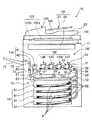
図2は、露光器34の外形の概略を示す図である。LEDアレイ81は発光素子であるLED素子がプリント基板82上に、例えば一列に等間隔(A4用紙サイズで解像度600dpiの場合で例えば約42.3μm間隔)で配置されたもので、例えば5120個のLED素子が主走査方向に並んだものである。ここで、主走査方向とは露光器34のLEDアレイ81が配列された方向で、記録用紙Pの給紙方向に対して垂直な方向である。これに対して、副走査方向とは主走査方向に垂直な方向であり、記録用紙Pに対してLEDアレイ81が相対的に移動する方向である。各LED素子は、描画される画像を形作る各ドットに対応する。LED素子の光路上にはセルフォックレンズ(日本硝子の登録商標)83が等間隔に例えば2列に配列されている。セルフォックレンズ83はLED素子からの光を結像するための円柱状のレンズを配列したものである。基準ピン84は露光器34を画像形成部132の各ユニット13Y,13M,13C,13Kに固定するときの位置を決めるためのもので、これにより露光器34は正しい位置に固定される。 FIG. 2 is a view showing an outline of the outer shape of the
図1に戻って、静電潜像に現像器32からトナーが供給されることにより、感光体ドラム31の周面にトナー像が形成される。各感光体ドラム31の同図における左方下部位置には感光体ドラム31の周面の残留トナーを除去してクリーニングするクリーニング装置35が設けられている。クリーニング装置35によって清浄化処理された感光体ドラム31の周面は、新たな帯電処理のために帯電器33へ向かうことになる。 Returning to FIG. 1, toner is supplied to the electrostatic latent image from the developing
各感光体ドラム31の下方位置には、搬送面が各感光体ドラム31と対向するように配設された転写搬送ベルト20が設けられている。この転写搬送ベルト20は、ブラック用ユニット13Kの若干下流側に設けられた駆動ローラ21と、イエロー用ユニット13Yの若干上流側に設けられた従動ローラ22とに掛け回され、駆動ローラ21の駆動回転によって、図上反時計方向に向けて周回する。そして、用紙貯留部15から供給された記録用紙Pは、この転写搬送ベルト20の周回に誘導されて感光体ドラム31の周面に当接しながら移動し、転写処理が施される。 A
従動ローラ22の上部には、周面が当該従動ローラ22の周面と対向した押えローラ(不図示)が設けられ、後述するレジストローラ対54から給紙された記録用紙Pは、この押えローラの周面に案内されて、転写搬送ベルト20上へ供給される。 A press roller (not shown) whose peripheral surface is opposed to the peripheral surface of the driven
定着部134は、画像形成部132で転写された記録用紙P上のトナー像に対し定着処理を施すものであり、互いに上下に対向配置されたヒートローラ41と加圧ローラ42とを備えている。転写搬送ベルト20の周回によって画像形成部132から導出された転写処理済の記録用紙Pは、これらヒートローラ41および加圧ローラ42の間で加熱されつつ押圧挟持され、それにより熱処理が加えられることによりトナー画像が定着される。その結果、記録用紙P上に安定したカラー画像が形成される。定着処理の完了したカラー画像付の記録用紙Pは、排紙搬送路72を通って装置本体11の左側壁から突設された排紙トレイ71へ向けて排出される。 The fixing
用紙貯留部15は、装置本体11に挿脱自在に装着された複数段の用紙トレイ51を有している。各用紙トレイ51には、それぞれ記録用紙Pの束が貯留される。そして、選択された用紙トレイ51の用紙束からピックアップローラ52の駆動により、記録用紙Pが1枚ずつ繰り出され、給紙搬送路53を通って画像形成部132へ導入される。給紙搬送路53の下流端には、転写搬送ベルト20の上流端に臨んだレジストローラ対54が設けられ、記録用紙Pは、このレジストローラ対54のニップによって安定した状態で転写搬送ベルト20へ給紙される。 The
更に、装置本体11内に記録用紙Pに対して両面印刷を行うための用紙反転部16が設けられている。この用紙反転部16は、画像形成部132と用紙貯留部15との間に介設された、片面に定着処理後の画像を有する記録用紙Pを一時的に貯留する中間トレイ61と、定着部14の直下流位置に設けられ、定着処理後の記録用紙Pに対して排紙搬送路72および返送搬送路73の何れか一方に記録用紙Pを振り分ける切換ガイド62と、一旦中間トレイ61に排紙された記録用紙Pを後端側から排紙する反転ローラ対63とを備えている。 Further, a
ユーザは、操作パネル部190の操作等を通じて両面印刷、通常の片面印刷の何れをも選択することができる。ユーザが、両面印刷を選択した場合には、図3に概略動作を示すように、記録用紙Pは、まず、転写搬送ベルト20に搬送されつつ表(おもて)面に画像の転写を受ける。この状態の記録用紙Pを符号P1で表す。図3には主走査方向x及び副走査方向yを同時に図示している。図3では、露光器34と記録用紙P1との間に介在する感光体ドラム31は省略されており、露光器34が記録用紙P1に直接対向するように描かれている。 The user can select either double-sided printing or normal single-sided printing through operation of the
記録用紙P1は、転写の後、切換ガイド62の切り換え操作によって返送搬送路73および反転ローラ対63を介して一旦中間トレイ61へ排紙される。この状態の記録用紙Pを符号P2で表している。記録用紙P2は、記録用紙P1に対して、前後が逆となり、さらに裏返しとなっている。続いて、記録用紙P2は、反転ローラ対63の逆回転によって後端側から排出され、反転搬送路74へ送られる。この状態にある記録用紙Pを符号P3で表している。記録用紙P3は、更に給紙搬送路53へ送られる。給紙搬送路53へ供給された記録用紙P3は、その後、記録用紙P4として、記録用紙P1に対して前後、表裏とも逆となって、後端側から転写搬送ベルト20へ再び侵入し、裏面に対して画像の転写を受けることとなる。このようにして、記録用紙Pに対する両面印刷が実現する。 After the transfer, the recording sheet P1 is temporarily discharged to the
なお、用紙貯留部15、ピックアップローラ52、給紙搬送路53、レジストローラ対54、及び用紙反転部16は、用紙搬送部131(図4)を構成する。 The
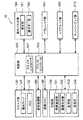
図4は画像形成装置10の主として電気的構成を示すブロック図である。画像形成装置10は、装置全体の動作制御を司る制御部100を備えている。制御部100には、既述のスキャナ部120、画像処理部160、画像メモリ140、記録部130及び操作パネル部190の他に、パラレルインタフェース(I/F)部181、シリアルインタフェース(I/F)部182、及びネットワークインタフェース(I/F)部210が接続されている。 FIG. 4 is a block diagram mainly showing an electrical configuration of the
これらのインタフェース部181、182及び210を通じて、画像形成装置10には外部のパーソナルコンピュータ等の端末装置(不図示)を接続することが可能となっている。それにより、画像形成装置10は、外部の端末装置(不図示)から送られる画像データ及びプリント条件を指定するデータを受信することにより、送られた画像データに基づいて記録用紙Pに画像を記録することが可能である。ネットワークインタフェース部210は、ローカルエリアネットワーク(LAN)等を通じて多数の端末装置を接続することを可能にする。また、ネットワークインタフェース部210は、LANが更に外部のインタネットにもつながることにより、インタネットを通じて各種のデータをやり取りすることをも可能にする。 Through these
制御部100は、不図示のCPU(Central Processing Unit;中央演算処理部)、このCPUの動作を規定するプログラムを格納するRAM或いはROM(Read Only Memory)等の記憶部を有している。すなわち、制御部100はコンピュータを備えている。それにより、制御部100は、スキャナコントローラ101及びプリンタコントローラ103として機能する。 The
スキャナコントローラ101は、スキャナ動作に必要な各部の動作を制御するものである。すなわち、スキャナコントローラ101は、主としてスキャナ部120、画像処理部160、及び画像メモリ140を制御することにより、原稿から画像データを読み取る動作から、当該画像データを画像メモリ140へ保存するまでの一連の動作を実現する。 The
これに対して、プリンタコントローラ103は、プリンタ動作に必要な各部の動作を制御するものである。すなわち、プリンタコントローラ103は、スキャナ部120により読み取られ、画像メモリ140に保存された画像データに基づいて記録部130を制御することにより、記録用紙Pへの画像の記録を実現する。プリンタコントローラ103は、更に、各種インタフェース部181、182、210を通じて外部の端末装置から送られる画像データを、画像メモリ140へ一旦保存すると共に、保存された画像データに基づいて記録部130を制御することにより、記録用紙Pへの画像の記録を実現する。プリンタコントローラ103が実現するこれらのプリンタ機能のうち、前者はコピー機能を構成するものであり、プリンタコントローラ103は、スキャナコントローラ101と連携して装置各部を制御することにより、コピー機能の一部としてのプリンタ機能を実現する。 On the other hand, the
制御部100としてのコンピュータが読み取ることによってこれらの機能を実現するための上記プログラムは、不図示のHDD(ハードディスクドライブ)等の不揮発性かつ大容量の外部記憶装置に格納しておき、上記RAM等の主記憶装置に適宜転送することにより、CPUによる実行に供することも可能である。上記プログラムは、ROM或いはCD−ROM等の記録媒体を通じて供給することも、ネットワークインタフェース部210に接続されるネットワーク等の伝送媒体を通じて供給することも可能である。プログラムがROMを通じて供給される場合には、当該プログラムを記憶したROMを制御部100に搭載することにより、CPUによる実行に供することができる。プログラムがCD−ROMを通じて供給される場合には、CD−ROM読み取り装置を、例えばパラレルインタフェース部181へ接続し、当該プログラムをRAM或いはHDDへ転送することにより、CPUによる実行に供することができる。また、プログラムが伝送媒体を通じて供給される場合には、ネットワークインタフェース部210等を通じて受信したプログラムをRAM或いはHDDへ転送することにより、CPUによる実行に供することができる。 The above-described program for realizing these functions by being read by a computer as the
操作パネル部190は、画像形成装置10の動作に必要な各種の指示を操作者(ユーザ)が入力するためのものである。操作パネル部190は、LCD(liquid crystal display)等を有し、画像形成装置10の操作に必要な各種操作メッセージが表示される表示部191と、コピー実行指示、印刷実行指示、文書の印刷部数、片面印刷か両面印刷かの選択、カラー印刷か単色印刷かの選択等が入力されるテンキー等からなる操作キー部192とを有している。カラー印刷が選択されたときには、プリンタコントローラ103は、画像形成部132を構成する4種のユニット13Y、13M、13C及び13Kの全てを動作させ、単色印刷が選択されたときには、ユニット13Kのみを動作させる。なお、表示部191は、タッチパネル機能を備え、操作者が当該タッチパネルに指等を触れることにより必要な指示を入力できる構成を有することが好ましい。この場合、当該タッチパネルは、操作キー部192の一形態に該当する。 The
図5は、プリンタコントローラ103のうち、露光器34に画像データを入力する機能を果たす部分を示す機能ブロック図である。当該部分は、本発明の露光画像入力装置の一実施形態に該当する。プリンタコントローラ103は、読出部200、切替部203及び補正データメモリ204を有している。読出部200は、画像メモリ140に記憶される画像データを読み出し、露光器34に入力するものである。 FIG. 5 is a functional block diagram showing a portion of the
露光器34は、LEDアレイ81等に加えて、不図示のラインメモリとデジタル・アナログコンバータ(D/Aコンバータ)とを有しており、読出部200が入力する例えば1ライン分のデジタル形式の画像データをラインメモリに保持し、保持される当該画像データをアナログ形式へ変換した上で、1ライン分のLEDアレイ81に印加する。これにより、LEDアレイ81が有する各LED素子は、対応する各画素の画像データが示す強度に変調された放射光を発生する。 The
露光器34は、複数ライン分のラインメモリを有していても良い。この場合には、露光器34は、記録用紙Pの搬送に同期して、ラインメモリの中からLEDアレイ81に印加すべき1ライン分の画像データを選択し、D/Aコンバータへ印加すると良い。そのためには、プリンタコントローラ103は、例えば、選択切替のための同期信号をも露光器34に入力すると良い。 The
露光器34は、色成分に対応した4種の露光ユニット34Y、34M、34C、34Kを有しており、これに対応して、読出部200は、4種の読出ユニット200Y、200M、200C、200Kを有している。読出ユニット200Y、200M、200C、200Kの各々は、第1読出部201と第2読出部202とを有している。第1読出部201は、画像メモリ140から画像データの1ページ分を画素毎に所定の順序で読み出しつつ露光器34に入力する。これに対して、第2読出部202は、画像メモリ140から画像データの1ページ分を画素毎に、第1読出部201が読み出す順序とは逆の順序で読み出しつつ露光器34に入力する。 The
切替部203は、第1読出部201と第2読出部202との一方を選択して動作させるものである。図4では図示を略したが、制御部100は、操作キー部192の操作によるユーザの指示等の入力を受け付けるキー操作受付部107を有している。キー操作受付部107が、片面印刷の指示を受け付けた場合には、切替部203は、第1読出部201と第2読出部202とのうち、第1読出部201のみを選択して動作させる。一方、キー操作受付部107が、両面印刷の指示を受け付けた場合には、切替部203は、画像メモリ140から1ページ分の画像データが読み出される毎に、第1読出部201と第2読出部202とを、交互に選択して動作させる。 The
なお、図5では、第1読出部201と第2読出部202とは、予め準備される2種類の読出部が部分的にも重複することなく設けられたものであるように描かれている。しかしながら、第1読出部201及び第2読出部202とは、図5の通りに、別体のものであっても良いが、一部が重複するものであっても良い。更に、第1読出部201及び第2読出部202は、同一の読出部200が、切替部203によって第2読出部201及び第2読出部202の何れかとして選択的に機能するものであっても良い。 In FIG. 5, the
補正データメモリ204は、主走査方向に沿った画素毎に、或いは、複数画素を1ブロックとしたブロック毎に、副走査方向への画素の位置ずれ量を記憶するためのメモリである。補正データメモリ204は、保持すべき補正データの変更を可能にするために、RAM、或いは読み書き可能なROM(例えば、フラッシュROMなどのEEPROM(電気的消去可能型ROM))を有するのが望ましい。 The
第1読出部201は、副走査方向に順次ずらしつつ主走査方向に沿って、画像メモリ140に記憶される画像データを画素毎に読み出すものである。その際に、第1読出部201は、補正データメモリ204に保持される補正データを参照する。すなわち、第1読出部201は、読み出すべき画素の位置を補正データが規定する量だけずらして画像データを読み出す。 The
第2読出部202は、第1読出部201による読み出し順序とは逆順に画像データを読み出すものであるので、副走査方向の逆方向に順次ずらしつつ、主走査方向の逆方向に沿って、画像メモリ140に記憶される画像データを画素毎に読み出す。その際に、第2読出部202は、補正データメモリ204に保持される補正データを参照することにより、読み出すべき画素の位置を補正データが規定する量の正負を反転し量だけずらして画像データを読み出す。 Since the
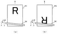
以下に、図6及び図7を参照しつつ、第1読出部201及び第2読出部202のより具体的な動作例を示す。図6は、記録用紙Pの表(おもて)面に大きな文字「R」を記録し(図6(a))、裏(うら)面にも同一形状の文字「R」を記録する(図6(b))ときの記録用紙Pとその移動方向と露光器34との間の概略的な関係を示す説明図である。図6は、露光器34の主軸方向が主走査方向xからずれて配置されている例を誇張して示すとともに、特に、主軸が直線性を保ちつつ主走査方向xに対して傾斜した例を描いている。なお、露光器34の各LED素子の位置ずれは、感光体ドラム31とこれに対向する各LED素子との位置関係が、間接的に記録用紙P上の主走査方向xに対するずれに反映されたものである。しかしながら、図6では簡略化のために、感光体ドラム31を介して記録用紙Pの上に間接的に現れる位置ずれを、露光器34の記録用紙P上の位置ずれとして直接的に表現している。 Hereinafter, a more specific operation example of the
図6(a)が示すように、表面に印刷が行われるときの記録用紙P1は、紙面の先端方向へ搬送される。これに対して、図6(b)が示すように、裏面に印刷が行われるときの記録用紙P4は、紙面の後端方向へ搬送される。すなわち、表面印刷がなされた記録用紙Pが裏返しとなり、且つあたかも180°回転された上で裏面印刷に供される。従って、裏面印刷が行われる場合には、同一の文字「R」と主走査方向x及び副走査方向yとの関係が何れも、表面印刷が行われるときとは逆となる。 As shown in FIG. 6A, the recording paper P1 when printing is performed on the front surface is conveyed toward the front end of the paper surface. In contrast, as shown in FIG. 6B, the recording paper P4 when printing is performed on the back surface is conveyed toward the rear end of the paper surface. That is, the recording paper P on which the front side printing has been performed is turned over and is rotated 180 degrees before being used for back side printing. Therefore, when the back side printing is performed, the relationship between the same character “R” and the main scanning direction x and the sub scanning direction y is opposite to that when the front side printing is performed.
図7は、画像データを画像メモリ140から読み取る工程を示す説明図である。図7(a)に示すように、画像メモリ140には、文字「R」を表現する画像データが保持されているものとする。分かり易くするために、図7(a)では、画像メモリ140のアドレス空間を、主走査方向x及び副走査方向yに沿って展開される画像データと相似形に、二次元展開されているかのように表現している。図7において、二次元的に表現された画像メモリ140のアドレス空間の主走査方向xの幅をHSIZEとし、主走査方向xに沿った画像データの有効幅をHVLDとしている。有効幅HVLDは、画像データによって一般には異なる。また、露光器34の各LED素子の主走査方向xからの位置ずれ量を関数f(x)で表現することとする。ここで、変数xは、主走査方向xに沿った位置を、基準位置からの画素数で表現したものである。関数f(x)の値は、副走査方向yに沿った画素数で表現され、一例として、副走査方向yの正方向へ向かうずれ量を正数で表し、その逆方向へ向かうずれ量を負数で表すものとする。 FIG. 7 is an explanatory diagram showing a process of reading image data from the
図7の例では、アドレス空間幅HSIZEを複数に等分割し、等分割されてなる複数領域をブロックA1〜ANで表す。かかるブロックは、画像データを主走査方向xに沿った複数の画素ごとに分割してなる領域に該当する。補正データメモリ204に記憶させるべき補正データは、ブロック番号m(=1,2,・・・・,N)の関数A[m]で与えられるものとする。すると、関数A[m]は、
A[m]=f(xm)・・・・(式1)
で与えられる。ここで、変数xmは、例えば、
xm=(1/N)×HSIZE×(m−1)・・・・(式2)
で与えられるものとする。In the example of FIG. 7, the address space width HSIZE is equally divided into a plurality, and a plurality of areas that are equally divided are represented by blocks A1 to AN. Such a block corresponds to a region formed by dividing image data into a plurality of pixels along the main scanning direction x. It is assumed that the correction data to be stored in the
A [m] = f (xm) (Equation 1)
Given in. Here, the variable xm is, for example,
xm = (1 / N) × HSIZE × (m−1) (Expression 2)
It shall be given by
図7の例では、総ブロック数Nは、N=5であり、補正データとしての関数A[m]は、A[m]=m−1、で表現される。 In the example of FIG. 7, the total number of blocks N is N = 5, and the function A [m] as correction data is expressed as A [m] = m−1.
図7(b)に示すように、表面印刷の場合には、第1読出部201は、まず第1ライン分の画像データを、主走査方向xに沿って1画素分ずつ読み出す。読み出される第1ライン分の画像データには、符号「1」を付している。第1読出部201は、第1ライン分の画像データを読み出す際に、補正データを参照することにより、第mブロックに属する画素に対しては、関数A[m]だけ副走査方向yにずれたライン上の画像データを読み出す。第1読出部201は、読み出すべき画像データのアドレスからブロック番号mを判断することができ、対応する関数A[m]を補正データメモリ204から読み出して参照する。第1読出部201は、1画素分の画像データを読み出す毎に、読み出した画像データを露光器34のラインメモリに順次入力する。 As shown in FIG. 7B, in the case of front side printing, the
第1ライン分の画像データの読み出しが終了すると、第1読出部201は、副走査方向yに1ライン分ずれた第2ライン分の画像データを読み出す。このとき、第1ライン分の画像データを読み出すときと同様に、第1読出部201は、補正データを参照することにより、第mブロックに属する画素に対しては、関数A[m]だけ副走査方向yにずれたライン上の画像データを読み出す。読み出される第2ライン分の画像データには、符号「2」を付している。以下同様に、第3ライン以下のラインの画像データが読み出され、1画素分毎に、露光器34のラインメモリに順次入力される。 When the reading of the image data for the first line is completed, the
図7(c)に示すように裏面印刷の場合には、図7(b)が示す表面印刷の場合とは、同一の画像データに対して、主走査方向xと副走査方向yとが何れも逆転する。このため、第2読出部202は、第1読出部201による読み出しの順序とは逆の順序で、画像データを読み出す。すなわち、第2読出部202は、図7(b)に示す主走査方向xに沿って、且つ補正データとしての関数A[m]を参照しつつ、画素毎に画像データを読み出す。すなわち、第2読出部202は、補正データを参照することにより、第mブロックに属する画素に対しては、図7(c)に示す副走査方向yに関数A[m]だけずれたライン上の画像データを読み出す。第2読出部202は、第1読出部201と同様に、読み出すべき画像データのアドレスからブロック番号mを判断することができ、対応する関数A[m]を補正データメモリ204から読み出して参照する。第2読出部202は、1画素分の画像データを読み出す毎に、読み出した画像データを露光器34のラインメモリに順次入力する。図7(c)に符号「1」「2」「3」・・・・で示すように、第2読出部202は、読み出し対象であるラインを副走査方向yに沿って順次ずらしてゆく。 As shown in FIG. 7C, in the case of back side printing, the main scanning direction x and the sub-scanning direction y are the same for the same image data as in the case of front side printing shown in FIG. Also reverses. For this reason, the
画像形成装置10は、以上のように動作するので、裏面印刷用に画像データを反転させて画像メモリ140に記憶させることなく、両面印刷を達成することができる。しかも、補正データメモリ204に記憶される補正データに基づいて、主走査方向xに対してずれた位置で画像データの画素毎の読み出しが行われるので、露光器34による露光のラインに設置誤差等に伴うずれがあっても、表面印刷、裏面印刷の何れに対しても当該ずれを補正しつつ、正常な印刷を達成することができる。 Since the
更に、画像形成装置10では、主走査方向xに沿った複数画素からなるブロック毎に、読み取るべき画素の位置を段階的に副走査方向yにずらすので、補正データとして、ブロックm毎にずれ量を規定するデータである関数A[m]が準備されれば足りる。すなわち、補正データメモリ204に記憶すべき補正データを簡素なものとすることができる。 Further, in the
なお、露光器34による露光のラインの補正すべきずれ量f(x)は、記録用紙Pの搬送方向を基準としたずれ、言い換えると主走査方向xに対するずれであっても良いが、カラー印刷を行う場合には、各色に対応した4種の露光ユニット34Y、34M、34C、34Kの間の相対的なずれであってもよい。記録用紙Pの搬送方向に対するずれは、視覚的には目立つものではないのに対して、露光ユニット34Y、34M、34C、34Kの間の相対的なずれは、視覚上に色ずれとして現れるので、より目立つからである。 The deviation amount f (x) to be corrected for the exposure line by the
なお、補正データは、画像形成装置10の工場出荷前に、露光器34のずれ量の計測値に基づいて、補正データメモリ204に格納されてもよく、それと共に、或いはそれに代えて、画像形成装置10がユーザの手に渡った後の適時に、メンテナンス要員の手により、或いはユーザ自身により入力されても良い。そのためには、色ずれを検知し、これを解消するための補正データを割り出すためのテストチャートを準備し、当該テストチャートをコピー或いはプリントすることにより、補正データを検出し、操作キー部192の操作を通じて当該補正データを、補正データメモリ204に更新的に記憶させるように画像形成装置10を構成しても良い。このような形態を採ることにより、露光器34のずれ量の経年変化にも対処することが可能となる。 The correction data may be stored in the
また、読出部200が画像メモリ140から読み出す画像データは、誤差拡散法等により二値化された画像であっても良く、256階調等の階調を有する多値画像であっても良い。何れの画像データを読み出しの対象とすべきかは、画像形成部132が何れのタイプであるかに依存する。 The image data read by the
(その他の実施の形態)
(1) 上記実施の形態では、第1及び第2読出部201、202は、主走査方向xに沿った複数画素からなるブロック毎に、読み出しの際のずれ量すなわち補正値を与える補正データを参照するように構成された。これに対して、第1及び第2読出部201、202は、主走査方向xに沿った画素毎に補正値を与える補正データを参照するように構成しても良い。それにより、よりきめの細かい補正を実現することができる。(Other embodiments)
(1) In the above-described embodiment, the first and
(2) 上記実施の形態では、露光画像入力装置を構成する読出部200及び切替部203は、制御部100の一部として、ソフトウェアを搭載したコンピュータによって実現された。これに対して、露光画像入力装置を制御部100とは別体のものとして、露光器34を駆動する装置部分である印字ヘッドの一部を成すものとして構成することも可能である。この場合に、読出部200及び切替部203を、ソフトウェアを要しない集積回路等のハードウェアのみで構成することも可能である。印字ヘッドには、上記実施の形態における露光器34の一部をなすラインメモリ及びD/Aコンバータをも、露光器34から別体のものとして含めることも可能である。 (2) In the above embodiment, the
(3) 上記実施の形態では、露光器34にはLEDアレイ81が用いられた。これに対して、露光器34としてレーザスキャン装置を用いることも可能であり、他のタイプの露光器を用いることも可能である。 (3) In the above embodiment, the
10 画像形成装置
16 用紙反転部
34 露光器
34Y、34M、34C、34K 露光ユニット
103 プリンタコントローラ(露光画像入力装置)
140 画像メモリ
200 読出部
200Y、200M、200C、200K 読出ユニット
204 補正データメモリ
A1〜AN ブロック
P、P1〜P4 記録用紙
x 主走査方向
y 副走査方向DESCRIPTION OF
140
Claims (4)
Translated fromJapanese前記画像データの画素位置の主走査方向からの副走査方向に沿ったずれ量を規定する補正データを記憶するための補正データメモリと、
前記補正データを参照することにより、前記画像メモリから前記画像データの1ページ分を画素毎に所定の順序で読み出しつつ前記露光器に入力する第1読出部と、
前記補正データを参照することにより、前記画像メモリから前記画像データの1ページ分を画素毎に前記所定の順序とは逆の順序で読み出しつつ前記露光器に入力するする第2読出部と、
前記画像メモリが記憶する前記画像データの1ページ分の読み出し毎に前記第1読出部と前記第2読出部とを交互に動作させる切替部と、を備え、
前記所定の順序は、読み取るべき画素の位置を前記補正データが規定するずれ量だけ前記副走査方向にずらしつつ画素毎に前記主走査方向に沿って読み出すと共に、当該主走査方向に沿った読み出しを副走査方向に順次ずらしつつ反復して実行する順序である露光画像入力装置。An exposure image input device that reads image data stored in an image memory and inputs the image data to an exposure device,
A correction data memory for storing correction data defining the amount of deviation of the pixel position of the image data along the sub-scanning direction from the main scanning direction;
Referring to the correction data, a first reading unit that inputs one page of the image data from the image memory to the exposure unit while reading the data in a predetermined order for each pixel;
A second reading unit that inputs one page of the image data from the image memory to the exposure unit while reading out one page of the image data from the image memory in a reverse order to the predetermined order by referring to the correction data;
A switching unit that alternately operates the first reading unit and the second reading unit every time one page of the image data stored in the image memory is read,
The predetermined order is to read along the main scanning direction for each pixel while shifting the position of the pixel to be read by the shift amount defined by the correction data in the sub-scanning direction for each pixel. An exposure image input device that is repeatedly executed while sequentially shifting in the sub-scanning direction.
当該プリンタ装置は、前記露光器として複数色に対応した複数の露光器を備えるタンデム型のカラープリンタ装置であって、
請求項1又は2の何れかに記載の前記露光画像入力装置を前記複数の露光器の一つ毎に備えるプリンタ装置。The printer device according to claim 3, wherein
The printer apparatus is a tandem type color printer apparatus including a plurality of exposure units corresponding to a plurality of colors as the exposure unit,
A printer apparatus comprising the exposure image input device according to claim 1 for each of the plurality of exposure devices.
Priority Applications (3)
| Application Number | Priority Date | Filing Date | Title |
|---|---|---|---|
| JP2005331461AJP2007136775A (en) | 2005-11-16 | 2005-11-16 | Exposed image inputting device, and printer |
| CNB2006101451155ACN100498569C (en) | 2005-11-16 | 2006-11-13 | Exposed image input device, printer apparatus, and image data input control method |
| US11/598,879US7719723B2 (en) | 2005-11-16 | 2006-11-14 | Exposed image input device, printer apparatus, and image data input control program product |
Applications Claiming Priority (1)
| Application Number | Priority Date | Filing Date | Title |
|---|---|---|---|
| JP2005331461AJP2007136775A (en) | 2005-11-16 | 2005-11-16 | Exposed image inputting device, and printer |
Publications (1)
| Publication Number | Publication Date |
|---|---|
| JP2007136775Atrue JP2007136775A (en) | 2007-06-07 |
Family
ID=38040464
Family Applications (1)
| Application Number | Title | Priority Date | Filing Date |
|---|---|---|---|
| JP2005331461APendingJP2007136775A (en) | 2005-11-16 | 2005-11-16 | Exposed image inputting device, and printer |
Country Status (3)
| Country | Link |
|---|---|
| US (1) | US7719723B2 (en) |
| JP (1) | JP2007136775A (en) |
| CN (1) | CN100498569C (en) |
Cited By (2)
| Publication number | Priority date | Publication date | Assignee | Title |
|---|---|---|---|---|
| JP2009028901A (en)* | 2007-07-24 | 2009-02-12 | Canon Inc | Recording device |
| JP2010118872A (en)* | 2008-11-12 | 2010-05-27 | Canon Inc | Image forming apparatus and control method thereof |
Families Citing this family (3)
| Publication number | Priority date | Publication date | Assignee | Title |
|---|---|---|---|---|
| JP4882925B2 (en)* | 2007-08-31 | 2012-02-22 | セイコーエプソン株式会社 | Image data processing apparatus and image data processing method |
| JP5874256B2 (en) | 2011-09-09 | 2016-03-02 | 株式会社リコー | Light source control device and image forming apparatus |
| CN112497934A (en)* | 2020-11-20 | 2021-03-16 | 衡阳和乐办公设备有限公司 | Automatic paper feeding device of printer |
Citations (3)
| Publication number | Priority date | Publication date | Assignee | Title |
|---|---|---|---|---|
| JPS62186277A (en)* | 1986-02-12 | 1987-08-14 | Casio Comput Co Ltd | recording device |
| JP2004174854A (en)* | 2002-11-26 | 2004-06-24 | Kyocera Mita Corp | Method and device for correcting imaging position deviation of exposure device in image formation apparatus |
| JP2005262655A (en)* | 2004-03-18 | 2005-09-29 | Kyocera Mita Corp | Printing head driving device, and printing head driving method |
Family Cites Families (13)
| Publication number | Priority date | Publication date | Assignee | Title |
|---|---|---|---|---|
| US4857123A (en)* | 1983-05-09 | 1989-08-15 | The Firestone Tire & Rubber Company | Method for ply application |
| JPH0745208B2 (en)* | 1986-04-07 | 1995-05-17 | 株式会社ブリヂストン | Method and apparatus for forming cylindrical tire constituent member |
| US4769104A (en)* | 1986-11-11 | 1988-09-06 | Bridgestone Corporation | Apparatus for sticking a tire component member |
| US5092946A (en)* | 1989-02-22 | 1992-03-03 | Bridgestone Corporation | Method for sticking a belt-like member and apparatus therefore |
| NL9301717A (en)* | 1993-10-06 | 1995-05-01 | Vmi Epe Holland | A method for adapting one side of a strip of flexible material to a reference side and belt strip feeder for feeding a belt strip onto a rotating superstructure drum. |
| US5935377A (en)* | 1994-08-30 | 1999-08-10 | Continental Ag | Device for joining ends of material strips |
| JP3686193B2 (en)* | 1996-11-20 | 2005-08-24 | 株式会社ブリヂストン | Centering method and apparatus for strip member |
| DE10119508C1 (en)* | 2001-04-21 | 2002-10-24 | Fischer Maschf Karl E | Material guide system for splicing machines |
| JP2004082396A (en) | 2002-08-23 | 2004-03-18 | Canon Inc | Full-line recording head, recording apparatus and recording method using the recording head |
| EP1710999B1 (en)* | 2005-04-08 | 2015-01-21 | Canon Kabushiki Kaisha | Color image forming apparatus |
| JP4817727B2 (en)* | 2005-06-24 | 2011-11-16 | キヤノン株式会社 | Color image forming apparatus |
| US7542706B2 (en)* | 2006-03-01 | 2009-06-02 | Kabushiki Kaisha Toshiba | Image forming apparatus, image forming method and image forming program |
| US7512493B2 (en)* | 2006-05-31 | 2009-03-31 | Honeywell International Inc. | High speed gyrocompass alignment via multiple Kalman filter based hypothesis testing |
- 2005
- 2005-11-16JPJP2005331461Apatent/JP2007136775A/enactivePending
- 2006
- 2006-11-13CNCNB2006101451155Apatent/CN100498569C/ennot_activeExpired - Fee Related
- 2006-11-14USUS11/598,879patent/US7719723B2/ennot_activeExpired - Fee Related
Patent Citations (3)
| Publication number | Priority date | Publication date | Assignee | Title |
|---|---|---|---|---|
| JPS62186277A (en)* | 1986-02-12 | 1987-08-14 | Casio Comput Co Ltd | recording device |
| JP2004174854A (en)* | 2002-11-26 | 2004-06-24 | Kyocera Mita Corp | Method and device for correcting imaging position deviation of exposure device in image formation apparatus |
| JP2005262655A (en)* | 2004-03-18 | 2005-09-29 | Kyocera Mita Corp | Printing head driving device, and printing head driving method |
Cited By (2)
| Publication number | Priority date | Publication date | Assignee | Title |
|---|---|---|---|---|
| JP2009028901A (en)* | 2007-07-24 | 2009-02-12 | Canon Inc | Recording device |
| JP2010118872A (en)* | 2008-11-12 | 2010-05-27 | Canon Inc | Image forming apparatus and control method thereof |
Also Published As
| Publication number | Publication date |
|---|---|
| CN100498569C (en) | 2009-06-10 |
| US20070109572A1 (en) | 2007-05-17 |
| US7719723B2 (en) | 2010-05-18 |
| CN1967401A (en) | 2007-05-23 |
Similar Documents
| Publication | Publication Date | Title |
|---|---|---|
| JP5100174B2 (en) | Image forming apparatus | |
| JP2007179005A (en) | Image forming apparatus | |
| JP2009086444A (en) | Image forming apparatus | |
| JP4562574B2 (en) | Tandem image forming apparatus | |
| JP2007237504A (en) | Image forming device, and image forming method | |
| JP2010102239A (en) | Image forming apparatus | |
| US7719723B2 (en) | Exposed image input device, printer apparatus, and image data input control program product | |
| JP4992805B2 (en) | Image forming apparatus and image forming control program | |
| US8155544B2 (en) | Image forming apparatus and image adjusting method involving a fluctuation-information acquiring unit and a control unit that forms a gradation pattern | |
| JP5639917B2 (en) | Image forming apparatus and image forming method | |
| JP2006103284A (en) | Printing system | |
| JP5219647B2 (en) | Image forming apparatus, image forming system, and image processing method | |
| JP3785805B2 (en) | Image forming apparatus | |
| EP1727353A1 (en) | Printing method and apparatus | |
| CN1312900C (en) | Image forming equipment | |
| JP5790111B2 (en) | Image forming apparatus, control method, and control program | |
| JP2018146653A (en) | Image forming apparatus, information processing apparatus, and program | |
| JP2005004121A (en) | Color image forming apparatus | |
| JP2006142713A (en) | Image forming apparatus, replenishment sheet display method thereof, and program for causing computer to execute the method | |
| JP2004112297A (en) | Image reading device and image forming device | |
| JP6882925B2 (en) | Image forming device, control program and control method | |
| US20080044209A1 (en) | Image forming apparatus | |
| JP4985283B2 (en) | Image forming apparatus and image forming method | |
| JP2005055699A (en) | Image forming apparatus | |
| JP5528738B2 (en) | Image forming apparatus and image forming method |
Legal Events
| Date | Code | Title | Description |
|---|---|---|---|
| A621 | Written request for application examination | Free format text:JAPANESE INTERMEDIATE CODE: A621 Effective date:20081027 | |
| A977 | Report on retrieval | Free format text:JAPANESE INTERMEDIATE CODE: A971007 Effective date:20110621 | |
| A131 | Notification of reasons for refusal | Free format text:JAPANESE INTERMEDIATE CODE: A131 Effective date:20110628 | |
| A02 | Decision of refusal | Free format text:JAPANESE INTERMEDIATE CODE: A02 Effective date:20111122 |