Movatterモバイル変換


[0]ホーム

URL:


JP2007136082A - Endoscope insertion aid - Google Patents

Endoscope insertion aid
Download PDF

Info

Publication number
JP2007136082A
JP2007136082AJP2005337621AJP2005337621AJP2007136082AJP 2007136082 AJP2007136082 AJP 2007136082AJP 2005337621 AJP2005337621 AJP 2005337621AJP 2005337621 AJP2005337621 AJP 2005337621AJP 2007136082 AJP2007136082 AJP 2007136082A
Authority
JP
Japan
Prior art keywords
state
endoscope
endoscope insertion
insertion portion
fixed
Prior art date
Legal status (The legal status is an assumption and is not a legal conclusion. Google has not performed a legal analysis and makes no representation as to the accuracy of the status listed.)
Pending
Application number
JP2005337621A
Other languages
Japanese (ja)
Inventor
Shigeki Matsuo
茂樹 松尾
Akira Suzuki
明 鈴木
Takahiro Kishi
孝浩 岸
Current Assignee (The listed assignees may be inaccurate. Google has not performed a legal analysis and makes no representation or warranty as to the accuracy of the list.)
Olympus Medical Systems Corp
Original Assignee
Olympus Medical Systems Corp
Priority date (The priority date is an assumption and is not a legal conclusion. Google has not performed a legal analysis and makes no representation as to the accuracy of the date listed.)
Filing date
Publication date
Application filed by Olympus Medical Systems CorpfiledCriticalOlympus Medical Systems Corp
Priority to JP2005337621ApriorityCriticalpatent/JP2007136082A/en
Publication of JP2007136082ApublicationCriticalpatent/JP2007136082A/en
Pendinglegal-statusCriticalCurrent

Links

Images

Landscapes

Abstract

Translated fromJapanese

【課題】簡単な構成で体腔管腔内への内視鏡挿入部の挿入を円滑かつ迅速におこない得ると共に良好な挿入操作性を備えた内視鏡挿入補助具を提供する。
【解決手段】筒状の挿入空間を形成する内向き面10aを有したチューブ10と、チューブの一端に連設される把持部11とからなるチューブ本体と、チューブ本体に設けられ挿入空間側に位置する突出位置とこの突出位置から内向き面方向へ変位した退避位置との間で、内向き面に対して移動可能な押圧面12bとを具備することを特徴とする。
【選択図】図1
An endoscope insertion assisting tool capable of smoothly and quickly inserting an endoscope insertion portion into a body cavity lumen with a simple configuration and having good insertion operability.
A tube body including a tube having an inward surface forming a cylindrical insertion space, a grip portion connected to one end of the tube, and provided on the tube body on the insertion space side. A pressing surface 12b that is movable with respect to the inward surface is provided between the protruding position that is positioned and a retracted position that is displaced inwardly from the protruding position.
[Selection] Figure 1

Description

Translated fromJapanese

この発明は、内視鏡挿入補助具、詳しくは内視鏡挿入部の挿入を円滑かつ迅速におこない得るよう補助する内視鏡挿入補助具に関するものである。  The present invention relates to an endoscope insertion assisting tool, and more particularly to an endoscope insertion assisting tool that assists in smoothly and quickly inserting an endoscope insertion portion.

従来より、細長状の挿入部を体腔内に挿入することにより、体腔内深部の臓器などを観察したり、必要に応じて挿入部に設けられている処置具挿通用チャンネル内に処置具を挿通させて、体腔内深部において各種の治療や処置などをおこない得るように構成される内視鏡が広く利用されている。  Conventionally, by inserting an elongated insertion part into a body cavity, an organ deep in the body cavity can be observed, and a treatment instrument is inserted into a treatment instrument insertion channel provided in the insertion part as necessary. Endoscopes configured to perform various treatments and treatments in the deep part of the body cavity are widely used.

細長状の挿入部を有する従来の内視鏡においては、一般に挿入部の先端側に湾曲部を設けて構成されている。この湾曲部は、これを構成する湾曲駒に接続される操作ワイヤを進退させることによって、例えば上下方向及び左右方向への湾曲動作を自在におこない得るように構成されている。この場合において、操作ワイヤの進退操作は、操作部に設けられている湾曲ノブなどの操作部材を、術者が手動で回動操作する等によっておこなわれるようになっているのが一般である。  In a conventional endoscope having an elongated insertion portion, a bending portion is generally provided on the distal end side of the insertion portion. The bending portion is configured to be able to freely perform, for example, a bending operation in the up-down direction and the left-right direction by advancing and retracting an operation wire connected to a bending piece constituting the bending portion. In this case, the advancement / retraction operation of the operation wire is generally performed by an operator manually turning an operation member such as a bending knob provided in the operation unit.

通常の場合、複雑に入り組んだ体腔内の管腔であって、例えば大腸などのように360°のループを描く管腔に対して内視鏡の挿入部を挿入する際には、その管腔に沿うように曲線を形成しながら挿入部を挿入することになる。この場合において、管腔の曲線部分では、図30,図31に示すように内視鏡102の挿入部102aと管腔の内壁(腸壁等)とが接触し滑り入ることで、術者が手100等によって挿入部102aを図に示す矢印Xに沿う方向へと押し込む力(挿入部の軸方向に沿う方向の押し込み力)の向きが管腔に沿う方向に変換され、これにより挿入部の先端部は体腔内の深部へと進み入るようになっている。  Usually, when inserting an insertion portion of an endoscope into a lumen in a complicated body cavity, such as a large intestine, in which a loop of 360 ° is drawn, for example, the lumen The insertion portion is inserted while forming a curve along the line. In this case, in the curved portion of the lumen, as shown in FIGS. 30 and 31, theinsertion portion 102a of theendoscope 102 and the inner wall (intestinal wall, etc.) of the lumen come into contact with each other and slip into the operator. The direction of the force (pushing force in the direction along the axial direction of the insertion portion) that pushes theinsertion portion 102a in the direction along the arrow X shown in the figure by thehand 100 or the like is converted into the direction along the lumen. The tip is advanced into the deep part of the body cavity.

また、例えばS字状結腸部のように管腔の曲率が大きい場合には、術者は、例えば湾曲ノブを操作して挿入部先端側に設けられる湾曲部を任意に湾曲動作させると共に、挿入部に対して捻り操作をおこなうことで、当該挿入部の先端部を体腔内深部の観察目的部位へと近付けるように挿入するという手段が用いられる。  Further, for example, when the curvature of the lumen is large as in the sigmoid colon, the operator operates the bending knob, for example, to arbitrarily bend the bending portion provided on the distal end side of the insertion portion and insert the bending portion. By performing a twisting operation on the portion, means for inserting the distal end portion of the insertion portion so as to approach the observation target site deep in the body cavity is used.

そうして、図32に示すように、挿入部の先端部が体腔内深部へと進むにつれて、挿入部と管腔内壁面(腸壁等)との接触部分が増えてくることから、挿入させる際の抵抗が強くなってくる。そこで、さらに挿入部の先端部を先へと進めるためには、その抵抗に抗する強い力量で挿入部を押し込む必要がある。  Then, as shown in FIG. 32, as the distal end portion of the insertion portion advances deeper into the body cavity, the contact portion between the insertion portion and the inner wall surface of the lumen (intestinal wall, etc.) increases. The resistance becomes stronger. Therefore, in order to further advance the distal end portion of the insertion portion, it is necessary to push the insertion portion with a strong force that resists the resistance.

ところが、上述したように、例えば図32に示すように挿入部が体腔内に向けてある程度挿入されて、挿入部と体腔内壁面との接触が増えてくると、挿入部の基端側から押し込む操作をおこなっても、図33に示すように管腔の入口近傍(直腸近傍)にて挿入部が折れ曲がってしまうなどにより、押し込む操作によっては挿入部の先端部を先に進めることができなくなってしまうという問題点がある。  However, as described above, for example, as shown in FIG. 32, when the insertion portion is inserted into the body cavity to some extent and the contact between the insertion portion and the body cavity inner wall surface increases, the insertion portion is pushed in from the proximal end side of the insertion portion. Even if the operation is performed, as shown in FIG. 33, the insertion portion is bent near the entrance of the lumen (near the rectum). There is a problem that.

また、複雑に入り組んだ大腸内の深部にまで内視鏡の挿入部を挿入するのに際して、患者への負担を抑えつつ、円滑かつ迅速に短時間で、当該挿入部を体腔内の管腔を挿通させ得るまでにはさらなる熟練を要することになる。特に、経験の浅い術者においては、挿入部を深部へと挿入していく際に、挿入方向を見失う等に起因して挿通に手間取ってしまったり、腸の走行状態を大きく変化させてしまうようなこともある。  In addition, when inserting the insertion portion of the endoscope into the deep part of the complicated intestine, the insertion portion can be moved smoothly and quickly in a short time while suppressing the burden on the patient. More skill is required before it can be inserted. Especially for inexperienced surgeons, when inserting the insertion part into the deep part, it may take time for insertion due to losing sight of the insertion direction, or greatly change the running state of the intestines. Sometimes it is.

このような点を考慮して、挿入部の挿入性を向上させるための種々の提案が従来よりなされている。  Considering such points, various proposals for improving the insertability of the insertion portion have been made conventionally.

例えば特開平10−286222号公報によって開示されている内視鏡挿入補助具は、内側チューブと外側チューブとによって構成される二重構造チューブからなり、当該チューブの内側空間に内視鏡挿入部を挿通し得るように構成し、内側チューブと外側チューブとを封止して形成される中間室(バルーン部)には、加圧吸引ポンプ等によって空気等の流体を供給または吸引することで、当該補助具を拡張または収縮し得るようになっている。  For example, an endoscope insertion assisting tool disclosed in Japanese Patent Laid-Open No. 10-286222 is composed of a double structure tube constituted by an inner tube and an outer tube, and an endoscope insertion portion is provided in the inner space of the tube. The intermediate chamber (balloon part) formed by sealing the inner tube and the outer tube is configured to be able to be inserted, and by supplying or sucking fluid such as air by a pressurized suction pump or the like, The assisting device can be expanded or contracted.

そして、加圧吸引ポンプを駆動させて中間室に対して空気(流体)を供給したときには、補助具は拡張するので、当該補助具とこれに挿通された挿入部とが一体化するようになっている。さらに、このとき外側チューブの外面側は体腔内の腸壁に接触し、腸内において固設されるようになっている。一方、加圧吸引ポンプを駆動させて中間室から空気(流体)を吸引したときには、当該補助具と挿通された挿入部とが別体となるよう、かつ腸壁に対する外側チューブの接触が解除されるように構成している。
特開平10−286222号公報
When the pressure suction pump is driven and air (fluid) is supplied to the intermediate chamber, the auxiliary tool expands, so that the auxiliary tool and the insertion portion inserted therethrough are integrated. ing. Further, at this time, the outer surface side of the outer tube comes into contact with the intestinal wall in the body cavity and is fixed in the intestine. On the other hand, when the pressure suction pump is driven and air (fluid) is sucked from the intermediate chamber, the auxiliary tool and the inserted insertion portion are separated from each other, and the contact of the outer tube with the intestinal wall is released. It is constituted so that.
JP-A-10-286222

ところが、前記特開平10−286222号公報によって開示されている内視鏡挿入補助具では、挿入部を挿入する際に加圧吸引ポンプによる拡張と収縮を繰り返す必要があり、その操作性が煩雑であるという問題点がある。  However, in the endoscope insertion aid disclosed by the Japanese Patent Laid-Open No. 10-286222, it is necessary to repeat expansion and contraction by the pressure suction pump when inserting the insertion portion, and the operability is complicated. There is a problem that there is.

本発明は、上述した点に鑑みてなされたものであって、その目的とするところは、簡単な構成でありながら、体腔管腔内への内視鏡挿入部の挿入を円滑かつ迅速におこなうことができると共に、より良好な挿入操作性を備えた内視鏡挿入補助具を提供することである。  The present invention has been made in view of the above-described points, and an object of the present invention is to smoothly and promptly insert an endoscope insertion portion into a body cavity lumen with a simple configuration. It is another object of the present invention to provide an endoscope insertion assisting tool that can perform better insertion operability.

上記目的を達成するために、本発明による内視鏡補助具は、筒状の挿入空間を形成する内向き面を有したチューブと、前記チューブの一端に連設される把持部とからなるチューブ本体と、前記チューブ本体に設けられ、挿入空間側に位置する突出位置とこの突出位置から前記内向き面方向へ変位した退避位置との間で、前記内向き面に対して移動可能な押圧面とを具備することを特徴とする。  In order to achieve the above object, an endoscope auxiliary tool according to the present invention comprises a tube having an inward surface that forms a cylindrical insertion space, and a gripping portion that is connected to one end of the tube. A pressing surface that is movable with respect to the inward surface between a main body and a protruding position that is provided on the tube main body and is positioned on the insertion space side and a retracted position that is displaced from the protruding position toward the inward surface. It is characterized by comprising.

本発明によれば、簡単な構成でありながら、体腔管腔内への内視鏡挿入部の挿入を円滑かつ迅速におこなうことができると共に、より良好な挿入操作性を備えた内視鏡挿入補助具を提供することができる。  According to the present invention, it is possible to smoothly and quickly insert an endoscope insertion portion into a body cavity lumen with a simple configuration, and to insert an endoscope with better insertion operability. Auxiliary tools can be provided.

以下、図示の実施の形態によって本発明を説明する。
(第1の実施形態)
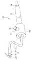
図1〜図8は、本発明の第1の実施形態に関し、このうち図1は、本実施形態の内視鏡挿入補助具の構成を示す斜視図である。なお、この図1及び以下に説明する図2〜図4では、本実施形態の内視鏡挿入補助具に対してその所定の部位に内視鏡挿入部を設置した状態を示している。図2は、図1の内視鏡挿入補助具に内視鏡挿入部を挿通させた状態における先端部近傍を示す要部拡大断面図である。図3は、図1の内視鏡挿入補助具に内視鏡挿入部を挿通させた状態であってかつ挿入部が非固定状態にある場合の当該内視鏡挿入補助具の概略断面を示す図である。図4は、図1の内視鏡挿入補助具に内視鏡挿入部を挿通させた状態であってかつ挿入部を固定状態とした場合の当該内視鏡挿入補助具の概略断面を示す図である。
The present invention will be described below with reference to the illustrated embodiments.
(First embodiment)
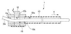
FIGS. 1-8 is related with the 1st Embodiment of this invention, Among these, FIG. 1 is a perspective view which shows the structure of the endoscope insertion auxiliary tool of this embodiment. Note that FIG. 1 and FIGS. 2 to 4 described below show a state in which an endoscope insertion portion is installed at a predetermined portion of the endoscope insertion aid of the present embodiment. FIG. 2 is an enlarged cross-sectional view of a main part showing the vicinity of the distal end portion in a state where the endoscope insertion portion is inserted through the endoscope insertion aid of FIG. FIG. 3 shows a schematic cross section of the endoscope insertion aid when the endoscope insertion portion is inserted through the endoscope insertion aid of FIG. 1 and the insertion portion is in an unfixed state. FIG. FIG. 4 is a diagram showing a schematic cross section of the endoscope insertion aid when the endoscope insertion portion is inserted through the endoscope insertion aid of FIG. 1 and the insertion portion is fixed. It is.

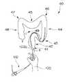
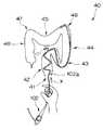
図5〜図8は、本実施形態の内視鏡挿入補助具を用いて内視鏡挿入部を体腔管腔内に挿入する際の手順を示す概念図である。このうち図5は、本実施形態の内視鏡挿入補助具を内視鏡挿入部と共に肛門からS字状結腸部まで挿入した状態を示す図である。図6は、内視鏡挿入部を図5の状態よりも深部(下行結腸部)へと進めた状態を示す図である。図7は、内視鏡挿入部を図6の状態よりも深部(横行結腸部)へと進めた状態を示す図である。図8は、内視鏡挿入部を図7の状態よりも深部(盲腸部近傍)まで進めた状態を示す図である。  5 to 8 are conceptual diagrams showing a procedure for inserting an endoscope insertion portion into a body cavity lumen using the endoscope insertion assisting tool of the present embodiment. Among these, FIG. 5 is a diagram showing a state where the endoscope insertion aid of the present embodiment is inserted from the anus to the sigmoid colon together with the endoscope insertion portion. 6 is a view showing a state in which the endoscope insertion portion is advanced to a deeper portion (descending colon portion) than the state of FIG. FIG. 7 is a view showing a state where the endoscope insertion portion is advanced to a deeper portion (transverse colon portion) than the state of FIG. 6. FIG. 8 is a view showing a state where the endoscope insertion portion is advanced deeper (near the caecum portion) than the state of FIG.

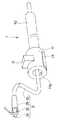
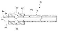
本実施形態の内視鏡挿入補助具1は、図1〜図4に示すように可撓性を有し筒状の挿入空間を形成する内向き面10a(図3,図4参照)を有した中空チューブ10と、この中空チューブ10の後側に設けられ使用時に術者が把持する把持部11とからなるチューブ本体によって主に構成されている。  The endoscopeinsertion assisting tool 1 of this embodiment has aninward surface 10a (see FIGS. 3 and 4) that forms a cylindrical insertion space with flexibility as shown in FIGS. It is mainly comprised by the tube main body which consists of thehollow tube 10 and theholding part 11 which are provided in the back side of thishollow tube 10, and an operator hold | grips at the time of use.

把持部11は、中空の略円筒形状によって構成され、内部に挿入体である内視鏡2の挿入部2aを挿通させ得る挿通部11aが形成されている。この挿通部11aには、図3,図4に示すように中空チューブ10が一体に連設されている。これにより、把持部11の挿通部11aに挿通される内視鏡2の挿入部2aは、当該挿通部11aから中空チューブ10の挿入空間を挿通した後、同中空チューブ10の先端側から突出するようになっている。  The grippingpart 11 is configured by a hollow, substantially cylindrical shape, and aninsertion part 11a through which theinsertion part 2a of theendoscope 2 as an insertion body can be inserted is formed. As shown in FIGS. 3 and 4, ahollow tube 10 is integrally connected to theinsertion portion 11 a. Thereby, theinsertion part 2a of theendoscope 2 inserted through theinsertion part 11a of thegrasping part 11 protrudes from the distal end side of thehollow tube 10 after inserting the insertion space of thehollow tube 10 from theinsertion part 11a. It is like that.

把持部11の外周上の略中央部近傍には、本内視鏡挿入補助具1に挿通される挿入部2aの固定状態を実現する固定部であってかつ挿入部2の固定状態と非固定状態とを切り換える操作部でもある固定解除操作部12が配設されている。この固定解除操作部12は例えば円柱状または角柱状の部材よりなり、その中程の部位であって、上記挿通部11aと重なる部位に、この挿通部11aと略同形同寸法の貫通孔12aが穿設されている。  Near the substantially central part on the outer periphery of the grippingpart 11 is a fixing part that realizes a fixing state of theinsertion part 2a inserted through the endoscopeinsertion assisting tool 1, and is fixed and unfixed to theinsertion part 2. A fixingrelease operation unit 12 which is also an operation unit for switching between states is provided. Theunlocking operation portion 12 is made of, for example, a columnar or prismatic member, and is a central portion of the through-hole 12a having substantially the same shape and the same size as theinsertion portion 11a. Is drilled.

そして、固定解除操作部12は、把持部11の挿通部11aに挿通される内視鏡2の挿入部2aの軸方向(挿通方向。図3の矢印Xに沿う方向)に対して略直交する方向(図3の矢印Yに沿う方向)に移動自在に配設されている。  And the fixingrelease operation part 12 is substantially orthogonal to the axial direction (insertion direction; the direction along the arrow X in FIG. 3) of theinsertion part 2a of theendoscope 2 inserted through theinsertion part 11a of thegrasping part 11. It is movably disposed in a direction (a direction along arrow Y in FIG. 3).

つまり、固定解除操作部12は、中空チューブ10の挿入空間側に突出する位置に配置される突出位置(図4参照)と、この突出位置から中空チューブ10の内向き面10a方向へ変位した退避位置(図3参照)との間で中空チューブ10の内向き面10aに対して移動可能に設けられている。  In other words, the unlockingoperation unit 12 has a protruding position (see FIG. 4) disposed at a position protruding toward the insertion space of thehollow tube 10 and a retreat displaced from the protruding position toward theinward surface 10a of thehollow tube 10. It is provided so as to be movable with respect to theinward surface 10a of thehollow tube 10 between positions (see FIG. 3).

また、把持部11の外周面上であって、上記固定解除操作部12が図4に示す矢印F1に沿う方向に移動したときに当接する部位には、例えば膜状のゴム部材や薄板状の板バネ部材等からなる弾性部材13が貼着されている。この弾性部材13は、固定解除操作部12が常に解除状態を維持するように配設されている。したがって、通常状態においては、図3に示す状態が維持されている。これにより、通常状態では、把持部11の挿通部11aと固定解除操作部12の貫通孔12aと中空チューブ10の内部空間が連通するようになっており、ここに内視鏡2の挿入部2aを抵抗無しに挿通させ得るようになっている。この状態を挿入部2aの非固定状態といい、このときの固定解除操作部12の位置を退避位置または非固定位置というものとする。  Further, on the outer peripheral surface of the grippingportion 11, a portion that comes into contact when the fixingrelease operation portion 12 moves in the direction along the arrow F <b> 1 shown in FIG. 4 is, for example, a film-like rubber member or a thin plate-like shape. Anelastic member 13 made of a leaf spring member or the like is attached. Theelastic member 13 is arranged so that the fixingrelease operation unit 12 always maintains the released state. Therefore, in the normal state, the state shown in FIG. 3 is maintained. Thereby, in the normal state, theinsertion part 11a of thegrip part 11, the throughhole 12a of the fixingrelease operation part 12, and the internal space of thehollow tube 10 communicate with each other, and theinsertion part 2a of theendoscope 2 is connected here. Can be inserted without resistance. This state is referred to as an unfixed state of theinsertion portion 2a, and the position of the fixingrelease operation unit 12 at this time is referred to as a retracted position or an unfixed position.

一方、図3の通常状態において、固定解除操作部12に対して図4の矢印F1に沿う方向への押圧力を加えると、同固定解除操作部12は、把持部11に対して同方向に移動する。これにより、把持部11の挿通部11aに対して固定解除操作部12の貫通孔12aの位置がずれることにより、両者の間の連通状態が閉鎖される。このとき、挿通部11aと貫通孔12aとの間に内視鏡2の挿入部2aが挿通されている状態にあれば、挿入部2aは、固定解除操作部12によって挿通部11aの内壁面に押し付けられる。つまり、固定解除操作部12の貫通孔12aの内周側の押圧面12bが内視鏡2の挿入部2aの外周面の所定部位に当接し、当該部位を図4の矢印F1方向に押圧する。これにより、挿入部2aの外周面の当該部位の近傍が挿通部11aの内壁面に向けて押し付けられ、よって進退し得ない状態に固定される。  On the other hand, when the pressing force in the direction along the arrow F1 in FIG. 4 is applied to the fixingrelease operation unit 12 in the normal state of FIG. Moving. Thereby, when the position of the through-hole 12a of the fixationrelease operation part 12 shifts | deviates with respect to theinsertion part 11a of the holdingpart 11, the communication state between both is closed. At this time, if theinsertion portion 2a of theendoscope 2 is inserted between theinsertion portion 11a and the throughhole 12a, theinsertion portion 2a is placed on the inner wall surface of theinsertion portion 11a by the fixingrelease operation portion 12. Pressed. That is, thepressing surface 12b on the inner peripheral side of the throughhole 12a of the unlockingoperation unit 12 abuts on a predetermined part on the outer peripheral surface of theinsertion part 2a of theendoscope 2, and presses the part in the direction of arrow F1 in FIG. . Thereby, the vicinity of the said site | part of the outer peripheral surface of theinsertion part 2a is pressed toward the inner wall face of theinsertion part 11a, and is fixed to the state which cannot advance / retreat.

この状態は、図4の矢印F1に沿う方向への押圧力が加えられている間は維持されることになる。この状態を挿入部2aの固定状態といい、このときの固定解除操作部12の位置を突出位置または固定位置というものとする。  This state is maintained while the pressing force in the direction along the arrow F1 in FIG. 4 is being applied. This state is referred to as a fixed state of theinsertion portion 2a, and the position of the fixingrelease operation unit 12 at this time is referred to as a protruding position or a fixed position.

なお、図4の状態(固定状態)において、固定解除操作部12に対する図4の矢印F1に沿う方向への押圧力を解除すれば、同固定解除操作部12は、弾性部材13の同図矢印F2に沿う方向への復元弾性力によって図3の状態へと復帰するようになっている。  In the state of FIG. 4 (fixed state), if the pressing force in the direction along the arrow F1 of FIG. It returns to the state of FIG. 3 by the restoring elastic force in the direction along F2.

また、中空チューブ10は、上述したように可撓性を有する部材によって構成されていると共に、その内側表面及び外側表面共に潤滑性を有する部材、例えばポリウレタン等によって形成されるチューブ部材である。したがって、中空チューブ10の内向き面10aは、固定解除操作部12の押圧面12bと比較して潤滑性を有している。  Further, thehollow tube 10 is a tube member formed of a flexible member as described above, and a member having lubricity on the inner surface and the outer surface thereof, such as polyurethane. Therefore, theinward surface 10 a of thehollow tube 10 has lubricity compared to thepressing surface 12 b of the fixingrelease operation unit 12.

このように構成される本実施形態の内視鏡挿入補助具1を適用し得る内視鏡2は、図1に示すように、例えば、一般的な従来の医療用内視鏡と同様の構成からなるものである。  Anendoscope 2 to which the endoscopeinsertion assisting tool 1 of the present embodiment configured as described above can be applied, as shown in FIG. 1, for example, has the same configuration as a general conventional medical endoscope It consists of

即ち、内視鏡2の概略構成は、細長形状の挿入部2aと、この挿入部2aの基端側に設けられ各種の操作部材が設けられる操作部2bと、この操作部2bの側部から延出するユニバーサルコード2d等を備えて構成されている。そして、図示を省略しているが、ユニバーサルコード2dは、例えば光源ユニットやビデオプロセッサ等に接続されている。  That is, the schematic configuration of theendoscope 2 includes anelongated insertion portion 2a, anoperation portion 2b provided on the proximal end side of theinsertion portion 2a and provided with various operation members, and a side portion of theoperation portion 2b. The extendeduniversal cord 2d is provided. Although not shown, theuniversal cord 2d is connected to, for example, a light source unit or a video processor.

なお、本発明の内視鏡挿入補助具1が適用される内視鏡2において、その挿入部2aの先端部近傍については、例えば図2に示すように構成されているものとする。  In theendoscope 2 to which the endoscopeinsertion assisting tool 1 of the present invention is applied, the vicinity of the distal end portion of theinsertion portion 2a is configured as shown in FIG. 2, for example.

即ち、先端側から先端硬質部2eと、この先端硬質部2eの基端側に先端が連設される湾曲部2hと、この湾曲部2hの基端側に先端が連設される可撓部2g等によって構成されている。  That is, the distal endhard portion 2e from the distal end side, the curved portion 2h having the distal end connected to the proximal end side of the distal endhard portion 2e, and the flexible portion having the distal end connected to the proximal end side of the curved portion 2h. 2g and the like.

先端硬質部2eは、最先端部位に配設される先端部材と、これに連設される先端基端部材2hとによって構成されている。  The distal endhard portion 2e is configured by a distal end member disposed at the most distal portion and a distal end proximal end member 2h provided continuously therewith.

先端部材には、特に図示していないが観察像を結像させるための撮像光学系や観察対象物に対して照明を照射する照明光学系等の窓部や内視鏡挿入部内を挿通する処置具挿通用チャンネルに連通する処置具開口等が設けられている。先端基端部材の内部には、撮像素子等の各種の構成部材が配設されている。湾曲部2hには、挿入部2aの先端部近傍を上下方向及び左右方向への湾曲動作を可能とする湾曲機構が構成されている。  Although not particularly shown in the drawing, the distal end member is inserted through a window portion or an endoscope insertion portion such as an imaging optical system for forming an observation image or an illumination optical system for illuminating an observation object. A treatment instrument opening or the like communicating with the instrument insertion channel is provided. Various constituent members such as an image sensor are disposed inside the distal end base end member. The bending portion 2h is configured with a bending mechanism that allows the vicinity of the distal end portion of theinsertion portion 2a to bend vertically and horizontally.

この場合において、先端部材と先端基端部材との連設部位21a及び先端基端部材と湾曲部2hとの連設部位21bは、例えば糸巻接着等の手段によってそれぞれ連設されている。ここで、当該内視鏡2の挿入部2aにおける最大直径d1(図2参照)は、この連設部位21a,21bが相当することになる。  In this case, the continuous portion 21a between the distal end member and the distal end proximal end member and thecontinuous portion 21b between the distal end proximal end member and the bending portion 2h are continuously disposed, for example, by means such as pincushion bonding. Here, thecontinuous portions 21a and 21b correspond to the maximum diameter d1 (see FIG. 2) in theinsertion portion 2a of theendoscope 2.

そして、図2に示すように、本実施形態の内視鏡挿入補助具1の中空チューブ10の内径d2は、挿入部2aの最大直径d1よりも大となるように設定されている。したがって、これにより中空チューブ10の管腔内に挿入部2aを挿通させることができるようになっている。  As shown in FIG. 2, the inner diameter d2 of thehollow tube 10 of theendoscope insertion aid 1 of the present embodiment is set to be larger than the maximum diameter d1 of theinsertion portion 2a. Accordingly, theinsertion portion 2 a can be inserted into the lumen of thehollow tube 10.

通常の内視鏡においては、挿入部における最大直径部分は先端硬質部にある。しかし、本実施形態においては、挿入部における先端硬質部を除く可撓部において、図2に示すように前記先端硬質部最大径より大きい径の部分がある。なお、通常の内視鏡のように、先端硬質部において最大直径を有する挿入部としても良いのは言うまでもない。  In a normal endoscope, the maximum diameter portion in the insertion portion is in the distal end hard portion. However, in the present embodiment, the flexible portion excluding the distal end hard portion in the insertion portion includes a portion having a diameter larger than the maximum diameter of the distal end hard portion as shown in FIG. Needless to say, an insertion portion having a maximum diameter at the distal end hard portion may be used as in a normal endoscope.

このように構成される内視鏡2の挿入部2aを本実施形態の内視鏡挿入補助具1を用いて体腔管腔に挿入する際の手順について、図3,図4及び図5〜図8を用いて、以下に詳述する。なお、以下の説明は、内視鏡挿入補助具1を用いて内視鏡2の挿入部2aを大腸へと挿入する場合の手技の例示である。  FIG. 3, FIG. 4 and FIG. 5 to FIG. 5 show the procedure for inserting theinsertion portion 2a of theendoscope 2 configured in this way into the body cavity lumen using theendoscope insertion aid 1 of this embodiment. 8 will be described in detail below. The following description is an example of a procedure when theinsertion portion 2a of theendoscope 2 is inserted into the large intestine using the endoscopeinsertion assisting tool 1.

まず、内視鏡2の挿入部2aを内視鏡挿入補助具1を用いて体腔管腔に挿入するのに先立って、挿入部2aを内視鏡挿入補助具1にセットする。即ち、本実施形態の内視鏡挿入補助具1が図3の通常状態にあるときに、内視鏡2の挿入部2aを、その先端側を把持部11の挿通部11aの基端側から挿入し、同挿通部11aを挿通させ、固定解除操作部12の貫通孔12aを経て中空チューブ10の内部空間に挿通させる。そして、挿入部2aの最先端部を中空チューブ10の先端部近傍に配置させる。この場合において、挿入部2aの最先端部は、中空チューブ10の先端部より突出しない位置、即ち挿入部2aの最先端面と中空チューブ10の先端面とが面一になる状態、若しくは挿入部2aの最先端部が、中空チューブ10の先端部より没入した状態に設定する。また、挿入部2aの最先端部が、中空チューブ10の先端部より若干突出した状態でも構わない。  First, prior to inserting theinsertion portion 2 a of theendoscope 2 into the body cavity lumen using the endoscopeinsertion assisting tool 1, theinsertion portion 2 a is set on the endoscopeinsertion assisting tool 1. That is, when theendoscope insertion aid 1 of the present embodiment is in the normal state of FIG. 3, theinsertion portion 2 a of theendoscope 2 is moved from the proximal end side of theinsertion portion 11 a of thegrip portion 11. Theinsertion portion 11 a is inserted, and theinsertion portion 11 a is inserted through the throughhole 12 a of the fixingrelease operation portion 12 into the inner space of thehollow tube 10. And the most advanced part of theinsertion part 2a is arrange | positioned in the front-end | tip part vicinity of thehollow tube 10. FIG. In this case, the most distal portion of theinsertion portion 2a does not protrude from the distal end portion of thehollow tube 10, that is, the distal end surface of theinsertion portion 2a and the distal end surface of thehollow tube 10 are flush with each other, or the insertion portion. The state where the most advanced part of 2a is immersed from the tip part of thehollow tube 10 is set. Further, the leading end of theinsertion portion 2 a may be slightly protruded from the distal end portion of thehollow tube 10.

この状態において、術者(特に図示せず)は、把持部11を把持しつつ、固定解除操作部12に対して図4に示す矢印F1に沿う方向への押圧力を加える。すると、この固定解除操作部12は弾性部材13の弾性力に抗して同方向に移動する。  In this state, the surgeon (not shown) applies a pressing force in the direction along the arrow F <b> 1 shown in FIG. 4 to the fixationrelease operation unit 12 while holding the holdingunit 11. Then, the fixingrelease operation unit 12 moves in the same direction against the elastic force of theelastic member 13.

このとき固定解除操作部12の貫通孔12aの内壁面は、挿入部2aの外周面に当接して、この挿入部2aを挿通部11aの内壁面に向けて押し付ける。これにより、挿入部2aは、内視鏡挿入補助具1の内部において、その軸方向(図3の矢印Xに沿う方向)への進退が規制される固定状態(図4の状態)となる。術者は、把持部11を把持し続けることにより、この固定状態を維持し続ける。  At this time, the inner wall surface of the through-hole 12a of the fixingrelease operation unit 12 comes into contact with the outer peripheral surface of theinsertion portion 2a and presses theinsertion portion 2a toward the inner wall surface of theinsertion portion 11a. Thereby, theinsertion part 2a will be in the fixed state (state of FIG. 4) in which the advance / retreat to the axial direction (direction along arrow X of FIG. 3) is controlled inside the endoscope insertionauxiliary tool 1. The surgeon continues to maintain this fixed state by continuing to grip thegrip portion 11.

術者は、図4の固定状態を維持しながら、挿入部2aが挿通された状態の内視鏡挿入補助具1の先端部を、例えばベッド(特に図示せず)上に横たわっている患者(特に図示せず)の肛門41から大腸40内へと挿入する。このとき、術者は、例えば右手100にて把持部11及び固定解除操作部12を把持しつつ、左手(図示せず)にて内視鏡挿入補助具1の先端部を把持して肛門41からの挿入操作をおこなう。  The operator, for example, a patient (for example, a patient lying on the bed (not shown)) with the distal end portion of theendoscope insertion aid 1 in a state where theinsertion portion 2a is inserted while maintaining the fixed state of FIG. It is inserted into thelarge intestine 40 from the anus 41 (not shown). At this time, for example, the operator grasps the distal end portion of the endoscopeinsertion assisting tool 1 with the left hand (not shown) while grasping the graspingportion 11 and the fixationrelease operation portion 12 with theright hand 100, for example. Perform the insertion operation from.

この挿入操作は、内視鏡挿入補助具1の中空チューブ10の外周側を把持しながら、これを、同内視鏡挿入補助具1の軸方向に体腔内に向けて押し込むように進めていく操作である。これによって、内視鏡挿入補助具1は、内視鏡2の挿入部2aを内部に挿通させた状態で、大腸40内を深部に向かって進んでいく。  In this insertion operation, while grasping the outer peripheral side of thehollow tube 10 of theendoscope insertion aid 1, the insertion operation is advanced so as to be pushed into the body cavity in the axial direction of theendoscope insertion aid 1. It is an operation. Thereby, the endoscopeinsertion assisting tool 1 advances toward the deep portion in thelarge intestine 40 with theinsertion portion 2a of theendoscope 2 inserted therethrough.

この場合において、肛門41から挿入された内視鏡挿入補助具1は、術者の挿入操作によって直腸42からS字状結腸部43に向かって進んでいく。  In this case, the endoscopeinsertion assisting tool 1 inserted from theanus 41 proceeds from therectum 42 toward thesigmoid colon portion 43 by the operator's insertion operation.

内視鏡挿入補助具1がS字状結腸部43に到達すると、術者は、内視鏡2の操作部2bの湾曲操作や挿入部2aの捻り操作等の手元操作をおこなうことで、内視鏡挿入補助具1を、図5に示すようにS字状結腸部43の曲線部分を通過させる。  When the endoscopeinsertion assisting tool 1 reaches thesigmoid colon portion 43, the surgeon performs internal operations such as bending operation of theoperation portion 2b of theendoscope 2 and twisting operation of theinsertion portion 2a. Theendoscope insertion aid 1 is passed through the curved portion of thesigmoid colon portion 43 as shown in FIG.

挿入部2aをS字状結腸部43から、さらに深部へと進めると、内視鏡挿入補助具1の先端部は、図6に示すように下行結腸部44の近傍に達する。  When theinsertion portion 2a is advanced from thesigmoid colon portion 43 to a deeper portion, the distal end portion of theendoscope insertion aid 1 reaches the vicinity of the descendingcolon portion 44 as shown in FIG.

この状態において、術者は、図4の固定状態を解除する。即ち、把持部11の把持状態を解放することにより、固定解除操作部12に対する図4の矢印F1に沿う方向への押圧力を解除する。すると、固定解除操作部12は、弾性部材13の図4の矢印F2に沿う方向への復元弾性力によって図3の通常状態へと復帰して、図3の通常状態が維持される。これにより、内視鏡挿入補助具1に挿通されている挿入部2aは、挿通部11aと貫通孔12aと中空チューブ10の内部空間において、その軸方向、つまり図3の矢印Xに沿う方向に進退自在である非固定状態となる。  In this state, the operator releases the fixed state of FIG. That is, by releasing the gripping state of thegripping part 11, the pressing force in the direction along the arrow F1 in FIG. Then, the unlockingoperation unit 12 returns to the normal state of FIG. 3 by the restoring elastic force of theelastic member 13 in the direction along the arrow F2 of FIG. 4, and the normal state of FIG. 3 is maintained. Thereby, theinsertion portion 2a inserted through theendoscope insertion aid 1 is in the axial direction, that is, the direction along the arrow X in FIG. 3 in theinsertion space 11a, the throughhole 12a, and the internal space of thehollow tube 10. It is in a non-fixed state that can freely advance and retract.

次いで、術者は、図7に示すように内視鏡挿入補助具1をその位置に留置させた状態で、手100によって挿入部2aを押し込む挿入操作をおこなう。このとき、中空チューブ10の内面側は潤滑性を有して形成されていることから、挿入部2aは、S字状結腸部43においても中空チューブ10の内部を円滑に抵抗なく進むことになる。  Next, the surgeon performs an insertion operation of pushing theinsertion portion 2a with thehand 100 in a state where the endoscopeinsertion assisting tool 1 is left at the position as shown in FIG. At this time, since the inner surface side of thehollow tube 10 is formed with lubricity, theinsertion portion 2a smoothly proceeds through thehollow tube 10 without resistance even in thesigmoid colon portion 43. .

そして、挿入部2aの先端部は、図7に示すように横行結腸部45を経て、上行結腸部48を通過し、図8に示すように盲腸部49へと到達する。なお、脾湾曲46や肝湾曲47等の曲線部分においては、操作部2bの湾曲操作や挿入部2aの捻り操作等の手元操作をおこなって通過させる。  Then, the distal end portion of theinsertion portion 2a passes through the ascendingcolon portion 45 as shown in FIG. 7, passes through the ascendingcolon portion 48, and reaches thececum portion 49 as shown in FIG. The curved portions such as thesplenic curve 46 and theliver curve 47 are passed by performing a hand operation such as a bending operation of theoperation portion 2b or a twisting operation of theinsertion portion 2a.

このようにして、挿入部2aが、その目的部位である盲腸部49近傍に到達すると、続いて術者は、大腸40内の内視鏡検査をおこなうために、挿入部2aの引き戻し操作をおこなう。  In this way, when theinsertion portion 2a reaches the vicinity of thececal portion 49 that is the target portion, the operator subsequently performs a pull-back operation of theinsertion portion 2a in order to perform an endoscopic examination in thelarge intestine 40. .

そして、挿入部2aの先端部が肛門41から抜去された時点で、この内視鏡検査を終了する。  Then, when the distal end portion of theinsertion portion 2a is removed from theanus 41, this endoscopic examination is terminated.

以上説明したように上記第1の実施形態によれば、挿入部2aが固定保持した状態の内視鏡挿入補助具1を、体内管腔(実施形態においては大腸40)内の所定の部位まで挿通させた後、挿入部2aの固定状態を解除して、内視鏡挿入補助具1をその位置に留置した状態で、挿入部2aの挿入操作をおこなうようにしている。これにより、当該挿入部2aは、例えばS字状結腸部43等の曲線部等においては、内視鏡挿入補助具1の潤滑性を有する中空チューブ10の内部で移動することになるので、挿入部2aは通常の押し込み操作及び湾曲操作等の挿入操作によって、円滑かつ迅速に短時間で体内管腔(大腸40)内の深部にある目的部位まで到達させることができる。  As described above, according to the first embodiment, theendoscope insertion aid 1 in a state where theinsertion portion 2a is fixedly held is moved to a predetermined site in the body lumen (thelarge intestine 40 in the embodiment). After the insertion, theinsertion portion 2a is released from the fixed state, and the insertion operation of theinsertion portion 2a is performed in a state where the endoscopeinsertion assisting tool 1 is left in that position. Accordingly, theinsertion portion 2a moves inside thehollow tube 10 having lubricity of theendoscope insertion aid 1 in a curved portion such as thesigmoid colon portion 43, for example. Thepart 2a can reach a target site deep in the body lumen (large intestine 40) smoothly and quickly in a short time by an insertion operation such as a normal pushing operation and a bending operation.

また、挿入部2aの固定状態と非固定状態とを切り換える固定解除操作部12を、把持部11に設けることにより、把持部11を把持する操作のみで固定解除操作部12による挿入部2aの固定状態とすることができる。その一方で、固定解除操作部12は、弾性部材13の弾性力によって常に非固定状態を維持するように構成しているので、把持部11の把持状態を解除することのみで、挿入部2aの固定状態を解除することが容易にできる。  In addition, by providing the holdingunit 11 with the fixingrelease operation unit 12 that switches between the fixed state and the non-fixed state of theinsertion unit 2a, the fixingunit 2a can be fixed by the fixingrelease operation unit 12 only by the operation of holding the holdingunit 11. State. On the other hand, since the fixingrelease operation unit 12 is configured to always maintain the non-fixed state by the elastic force of theelastic member 13, it is only necessary to release the gripping state of the grippingunit 11, and The fixed state can be easily released.

(第2の実施形態)
次に、本発明の第2の実施形態の内視鏡挿入補助具について、図9〜図11に基づいて、以下に説明する。
(Second Embodiment)
Next, an endoscope insertion aid according to a second embodiment of the present invention will be described below with reference to FIGS.

本実施形態の内視鏡挿入補助具の基本的な構成は、上述の第1の実施形態と略同様の構成からなり、挿入部の固定状態と非固定状態とを切り換える固定非固定切換部の構成が異なるのみである。したがって、上述の第1の実施形態と同様の構成については、同じ符号を附してその詳細な説明は省略し、異なる部材についてのみ以下に詳述する。  The basic configuration of the endoscope insertion aid of this embodiment is substantially the same as that of the first embodiment described above, and is a fixed / non-fixed switching unit that switches between a fixed state and a non-fixed state of the insertion unit. Only the configuration is different. Therefore, the same components as those in the first embodiment described above are denoted by the same reference numerals, detailed description thereof is omitted, and only different members are described in detail below.

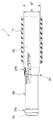
図9,図10,図11は、本発明の第2の実施形態の内視鏡挿入補助具を示し、このうち図9は、本実施形態の内視鏡挿入補助具の構成を示す斜視図である。図10は、図9の内視鏡挿入補助具に内視鏡挿入部を挿通させた状態であってかつ挿入部が固定状態にある場合の当該内視鏡挿入補助具の概略断面を示す図である。図11は、図9の内視鏡挿入補助具に内視鏡挿入部を挿通させた状態であってかつ挿入部を非固定状態とした場合の当該内視鏡挿入補助具の概略断面を示す図である。なお、図9,図10,図11では、本実施形態の内視鏡挿入補助具に対してその所定の部位に内視鏡挿入部を設置した状態を示している。  9, FIG. 10 and FIG. 11 show an endoscope insertion aid according to the second embodiment of the present invention. Among these, FIG. 9 is a perspective view showing the configuration of the endoscope insertion aid of this embodiment. It is. FIG. 10 is a diagram showing a schematic cross section of the endoscope insertion aid when the endoscope insertion portion is inserted through the endoscope insertion aid of FIG. 9 and the insertion portion is in a fixed state. It is. FIG. 11 shows a schematic cross section of the endoscope insertion aid when the endoscope insertion portion is inserted through the endoscope insertion aid of FIG. 9 and the insertion portion is in an unfixed state. FIG. In addition, in FIG.9, FIG10, FIG.11, the state which installed the endoscope insertion part in the predetermined site | part with respect to the endoscope insertion auxiliary tool of this embodiment is shown.

本実施形態の内視鏡挿入補助具1Aは、図9に示すように可撓性を有し筒状の挿入空間を形成する内向き面10aを有した中空チューブ10と、この中空チューブ10の後側に設けられ使用時に術者が把持する把持部11Aとからなるチューブ本体によって主に構成されているのは、上述の第1の実施形態と同様である。  As shown in FIG. 9, theendoscope insertion aid 1 </ b> A of the present embodiment has ahollow tube 10 having aninward surface 10 a that has flexibility and forms a cylindrical insertion space, and thehollow tube 10. It is the same as that of the above-mentioned 1st Embodiment that it is mainly comprised by the tube main body which is provided in the back side and consists of the holdingpart 11A which an operator holds at the time of use.

把持部11Aは、中空の略円筒形状によって構成され、内部に挿入体である内視鏡2の挿入部2aを挿通させ得る挿通部11aが形成されている。そして、把持部11Aの基端側には挿通部11aを挟持し得るように互いに対向する位置に形成される一対の固定爪部15が一体に配設されている。この固定爪部15は、弾性体によって形成されていて、図11に示す通常状態においては、同図矢印R1に沿う方向への弾性が作用している。したがって、図11の通常状態では、挿通部11aが開放状態となるようになっている。  11 A of grip parts are comprised by the hollow substantially cylindrical shape, and thepenetration part 11a which can penetrate theinsertion part 2a of theendoscope 2 which is an insertion body is formed in the inside. A pair of fixedclaw portions 15 formed at positions facing each other so as to sandwich theinsertion portion 11a are integrally disposed on the proximal end side of thegrip portion 11A. The fixedclaw portion 15 is formed of an elastic body, and in the normal state shown in FIG. 11, the elasticity in the direction along the arrow R1 is acting. Therefore, in the normal state of FIG. 11, theinsertion part 11a will be in an open state.

また、把持部11Aの外周側には、環状の硬質部材によって形成される固定非固定切換部である固定解除リング14が図11の矢印X1に沿う方向に摺動自在に配設されている。つまり、この固定解除リング14を任意に矢印X1に沿う方向に摺動させることで、当該内視鏡挿入補助具1Aに挿通させる内視鏡2の挿入部2aを非固定状態(図11の状態)と固定状態(図10の状態)とに切り換えることができるようになっている。  Further, on the outer peripheral side of thegrip portion 11A, a fixingrelease ring 14 which is a fixed / non-fixed switching portion formed by an annular hard member is disposed slidably in the direction along the arrow X1 in FIG. That is, by arbitrarily sliding the fixingrelease ring 14 in the direction along the arrow X1, theinsertion portion 2a of theendoscope 2 inserted through the endoscopeinsertion assisting tool 1A is not fixed (the state shown in FIG. 11). ) And a fixed state (state shown in FIG. 10).

つまり、固定爪部15は、固定解除リング14の矢印X1方向への摺動操作によって、中空チューブ10の挿入空間側に突出する位置に配置される突出位置(図10参照)と、この突出位置から中空チューブ10の内向き面10a方向へ変位した退避位置(図11参照)との間で中空チューブ10の内向き面10aに対して移動可能に設けられている。  That is, the fixedclaw portion 15 has a protruding position (see FIG. 10) arranged at a position protruding toward the insertion space side of thehollow tube 10 by the sliding operation of the fixingrelease ring 14 in the arrow X1 direction, and the protruding position. To the retracted position (see FIG. 11) displaced in the direction of theinward surface 10a of thehollow tube 10 so as to be movable with respect to theinward surface 10a of thehollow tube 10.

したがって、図11の通常状態においては、固定爪部15は同図矢印R1に沿う方向への弾性の作用により、同図に示すように挿通部11aは開放状態となっている。これにより、把持部11の挿通部11aと中空チューブ10の内部空間とが連通しているので、ここに内視鏡2の挿入部2aを抵抗無しに挿通させ得るようになっている。この状態を挿入部2aの非固定状態(図11の状態)といい、このときの固定爪部15及び固定解除リング14の位置を退避位置または非固定位置というものとする。  Therefore, in the normal state of FIG. 11, the fixedclaw portion 15 is in an open state as shown in FIG. 11 due to the elastic action in the direction along the arrow R1. Thereby, since theinsertion part 11a of the holdingpart 11 and the internal space of thehollow tube 10 are connected, theinsertion part 2a of theendoscope 2 can be inserted here without resistance. This state is referred to as an unfixed state of theinsertion portion 2a (the state shown in FIG. 11), and the positions of the fixingclaw portion 15 and the fixingrelease ring 14 at this time are referred to as a retracted position or an unfixed position.

一方、図11の通常状態において、固定解除リング14を図10の矢印X2に沿う方向へ摺動させて図10の状態にすると、同固定解除リング14は、固定爪部15を挿通部11aの内部に向けて互いが相対する方向(図11の矢印R1とは反対方向)へと押圧する。このとき、挿通部11aに内視鏡2の挿入部2aが挿通されている状態にあれば、挿入部2aは、固定爪部15の押圧面15aによって挟持される状態になる。  On the other hand, in the normal state of FIG. 11, when the fixingrelease ring 14 is slid in the direction along the arrow X2 in FIG. 10 to the state of FIG. 10, the fixingrelease ring 14 causes the fixingclaw portion 15 to be inserted into theinsertion portion 11a. It pushes in the direction (opposite direction of arrow R1 in FIG. 11) facing each other toward the inside. At this time, if theinsertion portion 2a of theendoscope 2 is inserted through theinsertion portion 11a, theinsertion portion 2a is sandwiched by thepressing surface 15a of the fixedclaw portion 15.

この状態を挿入部2aの固定状態(図10の状態)といい、このときの固定爪部15及び固定解除リング14の位置を突出位置または固定位置というものとする。なお、図10の状態(固定状態)において、固定解除リング14を図11の矢印X1に沿う方向へ摺動させて図11の状態にすると、固定爪部15は自身の図11の矢印R1に沿う方向への復元弾性力によって図10の状態に復元するようになっている。  This state is referred to as a fixed state of theinsertion portion 2a (the state shown in FIG. 10), and the positions of the fixingclaw portion 15 and the fixingrelease ring 14 at this time are referred to as a protruding position or a fixing position. In the state shown in FIG. 10 (fixed state), when the fixingrelease ring 14 is slid in the direction along the arrow X1 in FIG. 11 to the state shown in FIG. 11, the fixingclaw portion 15 moves to the arrow R1 in FIG. The state is restored to the state shown in FIG. 10 by the restoring elastic force along the direction.

つまり、本実施形態においては、当該内視鏡挿入補助具1Aに挿通される内視鏡2の挿入部2aの外周面の所定部位に当接し、当該部位を押圧する押圧面15aを有する固定爪部15と、この固定爪部15を作動させて非固定位置(退避位置)と固定位置(突出位置)を切り換える固定解除リング14とによって、挿入部2aの固定状態を実現する固定部が構成されている。  That is, in the present embodiment, a fixed claw having apressing surface 15a that comes into contact with a predetermined portion of the outer peripheral surface of theinsertion portion 2a of theendoscope 2 inserted through the endoscopeinsertion assisting tool 1A and presses the portion. The fixing portion that realizes the fixing state of theinsertion portion 2a is configured by theportion 15 and the fixingrelease ring 14 that operates the fixingclaw portion 15 to switch between the non-fixing position (retracted position) and the fixing position (projecting position). ing.

また、本実施形態においても、中空チューブ10は、上述の第1の実施形態と同様に材質の部材により形成されており、中空チューブ10の内向き面10aは、固定爪部15の押圧面15aと比較して潤滑性を有している。  Also in this embodiment, thehollow tube 10 is formed of a material member as in the first embodiment described above, and theinward surface 10a of thehollow tube 10 is thepressing surface 15a of the fixedclaw portion 15. Compared with, it has lubricity.

その他の構成は、上述の第1の実施形態と略同様である。また、本実施形態の内視鏡挿入補助具1Aを適用し得る内視鏡2は、上述の第1の実施形態と同様に、例えば、一般的な従来の医療用内視鏡と同様の構成からなるものである。また、同内視鏡2の挿入部2aの先端部近傍の構成についても、上述の第1の実施形態と同様である(図2参照)。  Other configurations are substantially the same as those in the first embodiment. In addition, theendoscope 2 to which the endoscopeinsertion assisting tool 1A of the present embodiment can be applied has the same configuration as, for example, a general conventional medical endoscope, as in the first embodiment described above. It consists of Further, the configuration in the vicinity of the distal end portion of theinsertion portion 2a of theendoscope 2 is the same as that in the first embodiment (see FIG. 2).

このように構成される本実施形態の内視鏡挿入補助具1Aを用いて内視鏡2の挿入部2aを体腔管腔(例えば大腸等)へと挿入する際の手順は、上述の第1の実施形態と略同様である(図5〜図8参照)。  The procedure for inserting theinsertion portion 2a of theendoscope 2 into a body cavity (for example, the large intestine) using the endoscopeinsertion assisting tool 1A of the present embodiment configured as described above is the first described above. This is substantially the same as the embodiment (see FIGS. 5 to 8).

なお、上述したように、本実施形態と上述の第1の実施形態とでは、固定非固定切換部の操作が異なる。したがって、内視鏡挿入補助具1Aによる挿入部2aの体腔管腔内への挿入手順においては、次に示すような違いがある。  As described above, the operation of the fixed / non-fixed switching unit is different between the present embodiment and the first embodiment described above. Therefore, there are the following differences in the insertion procedure of theinsertion portion 2a into the body cavity lumen by theendoscope insertion aid 1A.

即ち、挿入部2aを内視鏡挿入補助具1Aにセットする際においては、内視鏡2の挿入部2aを把持部11Aの挿通部11aから中空チューブ10の内部空間に挿通させて、挿入部2aの最先端部を中空チューブ10の先端部近傍に配置させる。この場合において、挿入部2aの最先端部は、中空チューブ10の先端部より突出しない位置、即ち挿入部2aの最先端面と中空チューブ10の先端面とが面一になる状態、若しくは挿入部2aの最先端部が、中空チューブ10の先端部より没入した状態に設定する。また、挿入部2aの最先端部が、中空チューブ10の先端部より若干突出した状態でも構わない。  That is, when setting theinsertion portion 2a to the endoscopeinsertion assisting tool 1A, theinsertion portion 2a of theendoscope 2 is inserted from theinsertion portion 11a of thegripping portion 11A into the internal space of thehollow tube 10 to insert theinsertion portion 2a. The most advanced part of 2a is arranged near the tip part of thehollow tube 10. In this case, the most distal portion of theinsertion portion 2a does not protrude from the distal end portion of thehollow tube 10, that is, the distal end surface of theinsertion portion 2a and the distal end surface of thehollow tube 10 are flush with each other, or the insertion portion. The state where the most advanced part of 2a is immersed from the tip part of thehollow tube 10 is set. Further, the leading end of theinsertion portion 2 a may be slightly protruded from the distal end portion of thehollow tube 10.

この状態においては、固定解除リング14は図11に示す非固定位置にある。そこで、術者は、固定解除リング14を図10の矢印X2に沿う方向へと摺動させて図10の固定位置に配置する。すると、固定解除リング14は、固定爪部15を弾性力に抗して図11の矢印R1とは反対方向へと移動させる。そして、固定爪部15は挿入部2aを対向する方向から挟持することで、同挿入部2aが進退し得ないように固定する。これにより、挿入部2aは固定状態となる。この状態とした後は、術者は把持部11Aから手を放したとしても挿入部2aの固定状態は維持される。  In this state, the fixingrelease ring 14 is in the non-fixed position shown in FIG. Therefore, the operator slides thefixation release ring 14 in the direction along the arrow X2 in FIG. 10 and arranges it at the fixed position in FIG. Then, the fixingrelease ring 14 moves the fixingclaw portion 15 in the direction opposite to the arrow R1 in FIG. 11 against the elastic force. And the fixed nail | clawpart 15 is fixed so that theinsertion part 2a cannot advance and retreat by pinching theinsertion part 2a from the direction which opposes. Thereby, theinsertion part 2a will be in a fixed state. After this state, even if the operator releases his / her hand from thegrip portion 11A, the fixed state of theinsertion portion 2a is maintained.

したがって、挿入部2aが挿通された状態の内視鏡挿入補助具1Aを大腸40内へと挿入する挿入操作をおこなう際には、術者は、常に把持部11Aを把持し続けている必要がない。  Therefore, when performing an insertion operation of inserting the endoscopeinsertion assisting tool 1A in a state where theinsertion portion 2a is inserted into thelarge intestine 40, the surgeon must always hold the graspingportion 11A. Absent.

以降、上述の第1の実施形態の場合と同様に内視鏡挿入補助具1Aの挿入操作を続けて、内視鏡挿入補助具1Aの先端部が下行結腸部44の近傍に達すると(図6参照)、この状態で、術者は、挿入部2aの固定状態(図10の状態)を解除する。  Thereafter, the insertion operation of theendoscope insertion aid 1A is continued as in the case of the first embodiment described above, and the distal end portion of theendoscope insertion aid 1A reaches the vicinity of the descending colon portion 44 (see FIG. 6), in this state, the operator releases the fixed state (the state shown in FIG. 10) of theinsertion portion 2a.

即ち、図10の状態に有る固定解除リング14を同図矢印Xに沿う方向へと摺動させて固定爪部15を解放する。これにより、固定爪部15は、図11の矢印R1に沿う方向への復元弾性力によって図11に示す通常状態へと復帰し、挿入部2aへの押圧力が解除される。これにより、内視鏡挿入補助具1Aに挿通されている挿入部2aは、挿通部11aと中空チューブ10との内部空間において、その軸方向、つまり図11の矢印X1に沿う方向に進退自在となる非固定状態になる。その他の挿入手順は、上述の第1の実施形態と全く同様である。  That is, the fixingclaw portion 15 is released by sliding the fixingrelease ring 14 in the state of FIG. 10 in the direction along the arrow X in FIG. Thereby, the fixed nail | clawpart 15 returns to the normal state shown in FIG. 11 with the restoring elastic force to the direction along arrow R1 of FIG. 11, and the pressing force to theinsertion part 2a is cancelled | released. As a result, theinsertion portion 2a inserted through theendoscope insertion aid 1A can advance and retreat in the axial direction of theinsertion portion 11a and thehollow tube 10 in the axial direction, that is, in the direction along the arrow X1 in FIG. It becomes a non-fixed state. Other insertion procedures are the same as those in the first embodiment.

そして、挿入部2aが目的部位である盲腸部49近傍に到達した後、術者は、続いて大腸40内の内視鏡検査をおこなうために、挿入部2aの引き戻し操作をおこなう。  Then, after theinsertion part 2a reaches the vicinity of thececal part 49, which is the target site, the operator performs a pull-back operation of theinsertion part 2a in order to perform an endoscopic examination in thelarge intestine 40.

そして、挿入部2aの先端部が肛門41から抜去された時点で、この内視鏡検査を終了する。  Then, when the distal end portion of theinsertion portion 2a is removed from theanus 41, this endoscopic examination is terminated.

以上説明したように上記第2の実施形態によれば、上述の第1の実施形態と同様の効果を得ることができる。  As described above, according to the second embodiment, the same effects as those of the first embodiment can be obtained.

これに加えて本実施形態においては、固定非固定切換部である固定解除リング14によって挿入部2aを固定状態とした後は、術者の手が内視鏡挿入補助具1Aから離れたとしても、その固定状態が維持されるように構成している。これにより、術者は、挿入部2aの固定状態を維持するために把持部11及び固定非固定切換部を常に把持している必要がなくなり、他の操作等のために、挿入部上の任意の位置を握ることができるようになる。  In addition, in this embodiment, even after the operator's hand is separated from theendoscope insertion aid 1A after theinsertion portion 2a is fixed by the fixingrelease ring 14 which is a fixed / non-fixed switching portion. The fixed state is maintained. This eliminates the need for the operator to always hold thegripping part 11 and the fixed / non-fixed switching part in order to maintain the fixed state of theinsertion part 2a. You will be able to hold the position.

(第3の実施形態)
次に、本発明の第3の実施形態の内視鏡挿入補助具について、図12〜図20に基づいて、以下に説明する。
(Third embodiment)
Next, an endoscope insertion aid according to a third embodiment of the present invention will be described below with reference to FIGS.

本実施形態の内視鏡挿入補助具の基本的な構成は、上述の第1の実施形態と略同様の構成であって、挿入部の固定状態と非固定状態とを切り換える固定非固定切換部の構成が異なるのみである。したがって、上述の第1の実施形態と同様の構成については、同じ符号を附してその詳細な説明は省略し、異なる部材についてのみ以下に詳述する。  The basic configuration of the endoscope insertion aid of the present embodiment is substantially the same as that of the first embodiment described above, and is a fixed / non-fixed switching unit that switches between a fixed state and a non-fixed state of the insertion unit. The only difference is the configuration. Therefore, the same components as those in the first embodiment described above are denoted by the same reference numerals, detailed description thereof is omitted, and only different members are described in detail below.

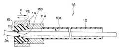
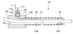
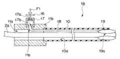
図12〜図20は、本発明の第3の実施形態に関し、このうち図12は、本実施形態の内視鏡挿入補助具の構成を示す斜視図である。図13は、図12の内視鏡挿入補助具に内視鏡挿入部を挿通させた状態であってかつ挿入部が非固定状態にある場合の当該内視鏡挿入補助具の概略断面を示す図である。図14は、図12の内視鏡挿入補助具に内視鏡挿入部を挿通させた状態であってかつ挿入部を固定状態とした場合の当該内視鏡挿入補助具の概略断面を示す図である。図15は、本実施形態の内視鏡挿入補助具における流体注入治具の構成を示す断面図であって、当該流体注入治具を内視鏡挿入補助具に装着した状態を示している。図16は、図15の流体注入治具の作用を示す図であって、当該流体注入治具を内視鏡挿入補助具から取り外すことで、バルーンの膨張状態が維持されるようすを示す図である。なお、図12〜図16では、本実施形態の内視鏡挿入補助具に対してその所定の部位に内視鏡挿入部を設置した状態を示している。  FIGS. 12 to 20 relate to the third embodiment of the present invention. Among these, FIG. 12 is a perspective view showing the configuration of the endoscope insertion aid of the present embodiment. 13 shows a schematic cross section of the endoscope insertion aid when the endoscope insertion portion is inserted through the endoscope insertion aid of FIG. 12 and the insertion portion is in an unfixed state. FIG. 14 is a diagram showing a schematic cross section of the endoscope insertion aid when the endoscope insertion portion is inserted through the endoscope insertion aid of FIG. 12 and the insertion portion is in a fixed state. It is. FIG. 15 is a cross-sectional view showing a configuration of a fluid injection jig in the endoscope insertion aid of the present embodiment, and shows a state in which the fluid injection jig is mounted on the endoscope insertion aid. FIG. 16 is a diagram illustrating the operation of the fluid injection jig of FIG. 15, in which the inflation state of the balloon is maintained by removing the fluid injection jig from the endoscope insertion aid. is there. 12 to 16 show a state in which an endoscope insertion portion is installed at a predetermined portion of the endoscope insertion aid of the present embodiment.

また、図17〜図20は、本実施形態の内視鏡挿入補助具を用いて内視鏡挿入部を体腔管腔内に挿入する際の手順を示す概念図である。このうち図17は、本実施形態の内視鏡挿入補助具を内視鏡挿入部と共に肛門からS字状結腸部まで挿入した状態を示す図である。図18は、内視鏡挿入部を図17の状態よりも深部(下行結腸部)へと進めた状態を示す図である。図19は、内視鏡挿入部を図18の状態よりも深部(横行結腸部)へと進めた状態を示す図である。図20は、内視鏡挿入部を図19の状態よりも深部(盲腸部近傍)まで進めた状態を示す図である。  FIGS. 17 to 20 are conceptual diagrams showing a procedure when an endoscope insertion portion is inserted into a body cavity lumen using the endoscope insertion assisting tool of the present embodiment. Among these, FIG. 17 is a diagram showing a state where the endoscope insertion aid of the present embodiment is inserted from the anus to the sigmoid colon together with the endoscope insertion portion. 18 is a view showing a state in which the endoscope insertion portion is advanced to a deeper portion (descending colon portion) than the state of FIG. FIG. 19 is a view showing a state in which the endoscope insertion portion is advanced to a deeper portion (transverse colon portion) than the state of FIG. FIG. 20 is a diagram showing a state where the endoscope insertion portion is advanced deeper (near the cecum portion) than the state of FIG.

本実施形態の内視鏡挿入補助具1Bは、図12に示すように可撓性を有し筒状の挿入空間を形成する内向き面10aを有した中空チューブ10と、この中空チューブ10の後側に設けられ使用時に術者が把持する把持部11Bとからなるチューブ本体によって主に構成されているのは、上述の第1の実施形態と同様である。  As shown in FIG. 12, the endoscopeinsertion assisting tool 1 </ b> B of the present embodiment has ahollow tube 10 having aninward surface 10 a that has flexibility and forms a cylindrical insertion space, and thehollow tube 10. It is the same as that of the above-mentioned 1st Embodiment that it is mainly comprised by the tube main body which consists of the holdingpart 11B which is provided in the back side and an operator hold | grips at the time of use.

把持部11Bは、管状部材からなり、その外周上の略中央部近傍には、本内視鏡挿入補助具1Bに挿通される挿入部2aの固定状態を実現する固定部であってかつ挿入部2aの固定状態と非固定状態とを切り換える固定非固定切換部の一部を構成する流体注入排出部17が配設されている。この流体注入排出部17は、中空の略円筒形状からなり、両端部には貫通孔17a,17bが穿設されている。  Thegrip portion 11B is made of a tubular member, and is a fixed portion that realizes a fixed state of theinsertion portion 2a inserted through theendoscope insertion aid 1B near the substantially central portion on the outer periphery thereof. A fluid injecting / dischargingunit 17 constituting a part of the fixed / non-fixed switching unit that switches between the fixed state and the non-fixed state of 2a is disposed. The fluid injection /discharge part 17 has a hollow, substantially cylindrical shape, and throughholes 17a and 17b are formed at both ends.

そして、把持部11Bには、流体注入排出部17の貫通孔17bに連設する貫通孔11bが形成されている。この貫通孔11bは、挿通部11aまで達しており、中空チューブ10の先端部近傍に配設される一対のバルーン19との間に流路を形成する管路18の一端部が配設されている。  And the through-hole 11b provided in a line with the through-hole 17b of the fluid injection /discharge part 17 is formed in the holdingpart 11B. The throughhole 11b reaches theinsertion portion 11a, and one end portion of apipe line 18 that forms a flow path between the pair ofballoons 19 provided in the vicinity of the distal end portion of thehollow tube 10 is provided. Yes.

つまり、管路18は、一端が流体注入排出部17の貫通孔17bに接続されており、把持部11の貫通孔11bを介して挿通部11aへと延出され、さらに挿通部11a及び中空チューブ10の内壁面に沿って当該中空チューブ10の先端部へと延出し、他端部がバルーン19に接続されている。  That is, one end of thepipe line 18 is connected to the throughhole 17b of the fluid injecting / dischargingunit 17, and is extended to theinsertion unit 11a through the throughhole 11b of the grippingunit 11, and further theinsertion unit 11a and the hollow tube. 10 extends to the tip of thehollow tube 10 along the inner wall surface, and the other end is connected to theballoon 19.

一方、流体注入排出部17の貫通孔17aには、この貫通孔17aを開閉するための開閉弁16が図13の矢印Yに沿う方向に摺動自在に配設されている。  On the other hand, an opening / closingvalve 16 for opening and closing the throughhole 17a is slidably disposed in the throughhole 17a of the fluid injecting / dischargingunit 17 in the direction along the arrow Y in FIG.

そして、後述する流体注入治具20(図15,図16参照)を用いることにより、流体注入排出部17から管路18を介してバルーン19に空気や水等の流体を注入し、同バルーン19を膨張させることができるようになっている。また、バルーン19を膨張させた状態(図14参照)において、流体注入排出部17の開閉弁16を図13に示す矢印F1に沿う方向に押圧操作することで、管路18及びバルーン19に注入されている流体を流体注入排出部17を介して外部へと排出し、膨張状態にあるバルーン19を緊縮状態とすることができるようになっている。  Then, by using a fluid injection jig 20 (see FIGS. 15 and 16) described later, a fluid such as air or water is injected from the fluid injection /discharge section 17 into theballoon 19 via thepipe line 18. Can be inflated. Further, in the state in which theballoon 19 is inflated (see FIG. 14), the on-offvalve 16 of the fluid injecting / dischargingunit 17 is pressed into the direction along the arrow F1 shown in FIG. The discharged fluid is discharged to the outside through the fluid injecting / dischargingunit 17 so that theballoon 19 in the inflated state can be brought into a contracted state.

一対のバルーン19は、中空チューブ10の先端部近傍において、その内壁面の沿わせて互いに対向する位置に配設されている。そして、当該バルーン19は、上述したように膨張状態(図14の状態)に変位させることによって、バルーン19の表面の一部は押圧面19aとして当該内視鏡挿入補助具1Bに挿通されている挿入部2aの外表面に当接しこれを押圧することにより当該挿入部2aを固定状態とする。また、当該バルーン19を緊縮状態(図13の状態)に変位させることによって、挿入部2aの外表面に対して当接状態にあったバルーン19の押圧部19aは、その押圧を解除して、挿入部2aを非固定状態とするようになっている。  The pair ofballoons 19 are arranged at positions facing each other along the inner wall surface in the vicinity of the distal end portion of thehollow tube 10. Then, as described above, theballoon 19 is displaced into the inflated state (the state shown in FIG. 14), so that a part of the surface of theballoon 19 is inserted into the endoscopeinsertion assisting tool 1B as thepressing surface 19a. Theinsertion portion 2a is fixed by contacting and pressing the outer surface of theinsertion portion 2a. Further, by displacing theballoon 19 in the contracted state (the state of FIG. 13), thepressing portion 19a of theballoon 19 that is in contact with the outer surface of theinsertion portion 2a releases the pressing, Theinsertion portion 2a is set in an unfixed state.

なお、中空チューブ10の内向き面10aは、バルーン19が膨張状態となったときに挿入部2aの外表面に当接する押圧部19aと比較して潤滑性を有している。  In addition, theinward surface 10a of thehollow tube 10 has lubricity compared with thepressing part 19a which contacts the outer surface of theinsertion part 2a when theballoon 19 is in an inflated state.

ここで、上述の流体注入治具20の構成について、図15,図16に基づいて説明する。  Here, the configuration of thefluid injection jig 20 will be described with reference to FIGS. 15 and 16.

流体注入治具20は、図15に示すように流体注入排出部17に嵌合する口金部22と、この口金部22に一端が連設され他端が例えばシリンジ等の流体供給装置(特に図示せず)に接続される流体注入管21とによって主に構成されている。  As shown in FIG. 15, thefluid injection jig 20 includes abase portion 22 that fits into the fluid injection /discharge portion 17, one end connected to thebase portion 22, and the other end of a fluid supply device such as a syringe (particularly, FIG. 15). And afluid injection pipe 21 connected to a main body (not shown).

口金部22の開放端は、上述したように流体注入排出部17に嵌合し得るようになっている。そのために、口金部22の開放端の内径寸法は流体注入排出部17の外径寸法よりも若干大となるように形成されている。なお、口金部22が流体注入排出部17に嵌合した状態では両者間において略気密状態が保持されるようになっている。この場合において、例えば口金部22の内径寸法を開放端から閉塞端側に向けて、徐々に狭まるように形成する等の工夫が考えられる。  The open end of thebase part 22 can be fitted into the fluid injection /discharge part 17 as described above. Therefore, the inner diameter dimension of the open end of thecap part 22 is formed to be slightly larger than the outer diameter dimension of the fluid injection /discharge part 17. In addition, in the state which the nozzle | cap | diepart 22 fitted to the fluid injection | pouringdischarge part 17, a substantially airtight state is maintained between both. In this case, for example, it is conceivable to form the inner diameter of thebase portion 22 so as to gradually narrow from the open end toward the closed end.

一方、口金部22の閉塞端には、外表面から外部に向けて突設される凸部22aと、内表面から内部に向けて突設される凸部22bとが形成されていて、この凸部22a,22bには、口金部22の内部空間と外部とを連設する流体流路22cが形成されている(特に図15参照)。  On the other hand, the closed end of thebase part 22 is formed with aconvex part 22a projecting outward from the outer surface and aconvex part 22b projecting inward from the inner surface. In theportions 22a and 22b, afluid flow path 22c that connects the internal space of thebase portion 22 and the outside is formed (see particularly FIG. 15).

凸部22aには、流体注入管21の一端部が接続されるようになっている。また、凸部22bは、当該口金部22が流体注入排出部17に装着された状態(図15の状態)となったときには、その頂部が開閉弁16に接触して、これを押圧するようになっている。  One end of thefluid injection tube 21 is connected to theconvex portion 22a. Further, theconvex portion 22b is configured such that, when thebase portion 22 is attached to the fluid injection / discharge portion 17 (the state shown in FIG. 15), the top portion of theconvex portion 22b comes into contact with the on-offvalve 16 and presses it. It has become.

これにより、口金部22を流体注入排出部17に装着する動作をおこなうと、これに伴って開閉弁16が開状態とされるようになっている。したがって、これにより流体注入治具20の流体注入管21から口金部22,流体注入排出部17,管路18を介してバルーン19へと至る流体通路が形成されるようになっている。  Thereby, when the operation | movement which mounts the nozzle | cap | diepart 22 to the fluid injection | pouringdischarge part 17 is performed, the on-offvalve 16 will be in an open state in connection with this. Accordingly, a fluid passage extending from thefluid injection tube 21 of thefluid injection jig 20 to theballoon 19 through thebase portion 22, the fluid injection /discharge portion 17, and theconduit 18 is formed.

その他の構成は、上述の第1の実施形態と略同様である。また、本実施形態の内視鏡挿入補助具1Aを適用し得る内視鏡2は、上述の第1の実施形態と同様に、例えば、一般的な従来の医療用内視鏡と同様の構成からなるものである。また、同内視鏡2の挿入部2aの先端部近傍の構成についても、上述の第1の実施形態と同様である(図2参照)。  Other configurations are substantially the same as those in the first embodiment. In addition, theendoscope 2 to which the endoscopeinsertion assisting tool 1A of the present embodiment can be applied has the same configuration as, for example, a general conventional medical endoscope, as in the first embodiment described above. It consists of Further, the configuration in the vicinity of the distal end portion of theinsertion portion 2a of theendoscope 2 is the same as that in the first embodiment (see FIG. 2).

このように構成される本実施形態の内視鏡挿入補助具1Bを用いて内視鏡2の挿入部2aを体腔管腔(例えば大腸等)へと挿入する際の手順は、上述の第1の実施形態と略同様である(図17〜図20参照)。  The procedure for inserting theinsertion portion 2a of theendoscope 2 into a body cavity lumen (for example, the large intestine) using the endoscopeinsertion assisting tool 1B of the present embodiment configured as described above is the first described above. This is substantially the same as the embodiment (see FIGS. 17 to 20).

なお、上述したように、本実施形態と上述の第1の実施形態とでは、固定非固定切換部の操作が異なる。したがって、内視鏡挿入補助具1Bによる挿入部2aの体腔管腔内への挿入手順においては、次に示すような違いがある。  As described above, the operation of the fixed / non-fixed switching unit is different between the present embodiment and the first embodiment described above. Therefore, there are the following differences in the insertion procedure of theinsertion portion 2a into the body cavity lumen by theendoscope insertion aid 1B.

即ち、挿入部2aを内視鏡挿入補助具1Bにセットする際には、まず、把持部11Bの挿通部11aから中空チューブ10の内部空間に挿入部2aを挿通させて、挿入部2aの最先端部を中空チューブ10の先端部近傍に配置させる。この場合において、挿入部2aの最先端部は、中空チューブ10の先端部より突出しない位置、即ち挿入部2aの最先端面と中空チューブ10の先端面とが面一になる状態、若しくは挿入部2aの最先端部が、中空チューブ10の先端部より没入した状態に設定する。また、挿入部2aの最先端部が、中空チューブ10の先端部より若干突出した状態でも構わない。  That is, when setting theinsertion portion 2a to the endoscopeinsertion assisting tool 1B, first, theinsertion portion 2a is inserted from theinsertion portion 11a of the graspingportion 11B into the inner space of thehollow tube 10, and the outermost portion of theinsertion portion 2a is inserted. The tip is disposed near the tip of thehollow tube 10. In this case, the most distal portion of theinsertion portion 2a does not protrude from the distal end portion of thehollow tube 10, that is, the distal end surface of theinsertion portion 2a and the distal end surface of thehollow tube 10 are flush with each other, or the insertion portion. The state where the most advanced part of 2a is immersed from the tip part of thehollow tube 10 is set. Further, the leading end of theinsertion portion 2 a may be slightly protruded from the distal end portion of thehollow tube 10.

この状態において、術者は、把持部11Bの流体注入排出部17に対して流体注入治具20を装着して、流体注入管21を介して流体供給装置より供給される流体をバルーン19へと送ることによって、当該バルーン19を膨張させるための操作をおこなう。  In this state, the operator attaches thefluid injection jig 20 to the fluid injection /discharge portion 17 of the graspingportion 11B, and supplies the fluid supplied from the fluid supply device via thefluid injection tube 21 to theballoon 19. By sending, the operation for inflating theballoon 19 is performed.

ここで、流体注入治具20を用いてバルーン19を膨張させる際の作用を主に図15,図16を用いて以下に説明する。  Here, the operation when theballoon 19 is inflated using thefluid injection jig 20 will be described below mainly with reference to FIGS.

上述のようにして、流体注入排出部17に対して流体注入治具20を装着すると、これにより、流体注入治具20の凸部22bが開閉弁16を図15に示す矢印Y1に沿う方向に押圧する。これにより、開閉弁16は、貫通孔17aを開状態にする。  When thefluid injection jig 20 is attached to the fluid injection /discharge portion 17 as described above, this causes theconvex portion 22b of thefluid injection jig 20 to move the on-offvalve 16 in the direction along the arrow Y1 shown in FIG. Press. Thereby, the on-offvalve 16 opens the through-hole 17a.

この状態で、流体注入治具20の流体注入管21を介して流体供給装置(図示せず)より流体を供給する。これにより、流体は、流体供給装置から流体注入管21,流体流路22cを通って口金部22の内部空間へと送り込まれる。次いで、同流体は、口金部22の内部空間から、開閉弁16により開状態とされている貫通孔17aを通って流体注入排出部17の内部空間に送り込まれる。さらに、同流体は、流体注入排出部17の内部空間から、流体注入排出部17の貫通孔17bに接続される管路18を介してバルーン19へと流入する。これによりバルーン19は図16に示すような膨張状態になる。  In this state, a fluid is supplied from a fluid supply device (not shown) through thefluid injection pipe 21 of thefluid injection jig 20. Thereby, the fluid is sent from the fluid supply device to the internal space of thebase part 22 through thefluid injection pipe 21 and thefluid flow path 22c. Next, the fluid is sent from the internal space of thebase part 22 into the internal space of the fluid injection /discharge part 17 through the through-hole 17 a opened by the on-offvalve 16. Further, the fluid flows from the internal space of the fluid injecting and dischargingportion 17 into theballoon 19 via thepipe line 18 connected to the throughhole 17 b of the fluid injecting and dischargingportion 17. As a result, theballoon 19 is in an inflated state as shown in FIG.

この状態で、流体注入治具20の口金部22を、図16に示す矢印Y2に沿う方向へと引き抜いて、同口金部22を流体注入排出部17から離脱させる。すると、開閉弁16は、流体注入排出部17の内部に充填されている流体の内圧によって同図16の矢印Y2に沿う方向へと移動して、開閉弁16を閉状態にする。これにより流体注入排出部17は、気密状態になる。したがって、流体注入排出部17に対して管路18を介して連設され、流体が充填されている状態のバルーン19の膨張状態が維持される。  In this state, thebase part 22 of thefluid injection jig 20 is pulled out in the direction along the arrow Y2 shown in FIG. 16, and thebase part 22 is detached from the fluid injection /discharge part 17. Then, the on-offvalve 16 moves in the direction along the arrow Y2 in FIG. 16 due to the internal pressure of the fluid filled in the fluid injecting / dischargingunit 17, and closes the on-offvalve 16. As a result, the fluid injecting / dischargingunit 17 becomes airtight. Therefore, the inflated state of theballoon 19 which is connected to the fluid injecting / dischargingunit 17 via thepipe line 18 and filled with the fluid is maintained.

このようにして、バルーン19が膨張状態にされると、中空チューブ10の内部に挿通されている状態の内視鏡2の挿入部2aは、同中空チューブ10の先端部において、バルーン19によって挟持され、これにより、挿入部2aは、その軸方向への進退が規制され固定状態になる(図16参照)。  In this way, when theballoon 19 is in an inflated state, theinsertion portion 2a of theendoscope 2 inserted into thehollow tube 10 is held by theballoon 19 at the distal end portion of thehollow tube 10. As a result, theinsertion portion 2a is fixed in a state where the axial movement of theinsertion portion 2a is restricted (see FIG. 16).

この状態において、術者は、挿入部2aが挿通された状態の内視鏡挿入補助具1Bの先端部を肛門41から大腸40内へと挿入する挿入操作をおこなう。このとき、術者は、上述の第2の実施形態と同様に、内視鏡挿入補助具1Bから手を放したとしても挿入部2aの固定状態が維持されるようになっている。したがって、術者は、この挿入操作をおこなう際には、図17に示すように、常に把持部11Bを把持し続けている必要がないのは、上述の第2の実施形態と同様である。  In this state, the surgeon performs an insertion operation of inserting the distal end portion of theendoscope insertion aid 1B in a state where theinsertion portion 2a is inserted from theanus 41 into thelarge intestine 40. At this time, similarly to the above-described second embodiment, even if the operator releases his / her hand from the endoscopeinsertion assisting tool 1B, the fixed state of theinsertion portion 2a is maintained. Therefore, when performing this insertion operation, as shown in FIG. 17, it is not necessary for the surgeon to always hold the holdingportion 11B, as in the second embodiment described above.

以降、上述の第1の実施形態の場合と同様に内視鏡挿入補助具1Bの挿入操作を続けて、内視鏡挿入補助具1Bの先端部がS字状結腸部43に到達すると、術者は、操作部2bの湾曲操作や挿入部2aの捻り操作等の手元操作をおこなって、内視鏡挿入補助具1Bを、図17に示すようにS字状結腸部43の曲線部分を通過させる。  Thereafter, when the insertion operation of theendoscope insertion aid 1B is continued in the same manner as in the case of the first embodiment described above, and the distal end portion of theendoscope insertion aid 1B reaches thesigmoid colon portion 43, an operation is performed. The person performs a hand operation such as a bending operation of theoperation portion 2b or a twisting operation of theinsertion portion 2a, and passes through the curved portion of thesigmoid colon portion 43 as shown in FIG. Let

挿入部2aをS字状結腸部43から、さらに深部へと進めると、内視鏡挿入補助具1Bの先端部は、図18に示すように下行結腸部44の近傍に達する。この状態で、術者は、挿入部2aの固定状態を解除する。  When theinsertion portion 2a is advanced from thesigmoid colon portion 43 to a deeper portion, the distal end portion of theendoscope insertion aid 1B reaches the vicinity of the descendingcolon portion 44 as shown in FIG. In this state, the operator releases the fixed state of theinsertion portion 2a.

即ち、術者は、開閉弁16に対して図13,図14に示す矢印F1に沿う方向への押圧力を加えることにより、開閉弁16を開状態にする。すると、流体注入排出部17の内部空間,管路18,バルーン19に充填されている流体、貫通孔17aから外部へと流出する。これによってバルーン19は図13等に示す緊縮状態になる。したがって、挿入部2aは非固定状態になり、その軸方向への進退が自在な状態になる。その後の挿入手順は、上述の第1の実施形態と全く同様である(図19,図20参照)。  That is, the surgeon opens the on-offvalve 16 by applying a pressing force to the on-offvalve 16 in the direction along the arrow F1 shown in FIGS. Then, the fluid filled in the internal space of the fluid injecting and dischargingportion 17, thepipe line 18 and theballoon 19, flows out from the throughhole 17 a. As a result, theballoon 19 is in a contracted state as shown in FIG. Accordingly, theinsertion portion 2a is in a non-fixed state and can be freely advanced and retracted in the axial direction. The subsequent insertion procedure is exactly the same as in the first embodiment described above (see FIGS. 19 and 20).

そして、挿入部2aが目的部位である盲腸部49近傍に到達した後(図20参照)、術者は、続いて大腸40内の内視鏡検査をおこなうために、挿入部2aの引き戻し操作をおこなう。  Then, after theinsertion portion 2a reaches the vicinity of thececal portion 49, which is the target site (see FIG. 20), the surgeon subsequently performs a pull-back operation of theinsertion portion 2a in order to perform an endoscopic examination in thelarge intestine 40. Do it.

また、挿入部2aの先端部近傍が内視鏡挿入補助具1Bの先端部近傍まで到達したら、その時点で、挿入部2aの引き戻し操作を一時中断し、内視鏡挿入補助具1Bを引き抜く。その後、挿入部2aの引き戻し操作を再開する。  Further, when the vicinity of the distal end portion of theinsertion portion 2a reaches the vicinity of the distal end portion of the endoscopeinsertion assisting tool 1B, at that time, the pull back operation of theinsertion portion 2a is temporarily interrupted, and the endoscopeinsertion assisting tool 1B is pulled out. Thereafter, the pull back operation of theinsertion portion 2a is resumed.

そして、挿入部2aの先端部が肛門41から抜去された時点で、この内視鏡検査を終了する。  Then, when the distal end portion of theinsertion portion 2a is removed from theanus 41, this endoscopic examination is terminated.

以上説明したように上記第3の実施形態によれば、上述の第1の実施形態と同様の効果を得ることができる。また、バルーン19を膨張状態にすることで、挿入部2aを固定状態にすることができ、開閉弁16を開状態にすることにより流体を放出しない限り、その固定状態を維持することができるので、上述の第2の実施形態と同様に挿入部2aを固定状態とした後は、術者の手が内視鏡挿入補助具1Bから離れたとしても、その固定状態が維持される。したがって操作性の向上に寄与することができる。  As described above, according to the third embodiment, the same effect as that of the first embodiment can be obtained. Further, theinsertion portion 2a can be fixed by inflating theballoon 19, and the fixed state can be maintained unless fluid is discharged by opening the on-offvalve 16. After theinsertion portion 2a is set in a fixed state as in the second embodiment, the fixed state is maintained even if the operator's hand moves away from theendoscope insertion aid 1B. Therefore, it can contribute to the improvement of operability.

また、膨張させることによって挿入部2aを固定状態とするバルーン19を中空チューブ10の先端側に配設したことにより、内視鏡挿入補助具1Bの挿入操作時において、例えば中空チューブ10の先端側が腸壁等に干渉することで捲れてしまうようなことがなく、確実な挿入をおこなうことができる。  In addition, since theballoon 19 that fixes theinsertion portion 2a by being inflated is disposed on the distal end side of thehollow tube 10, when the endoscopeinsertion assisting tool 1B is inserted, for example, the distal end side of thehollow tube 10 is There is no risk of drowning by interfering with the intestinal wall or the like, and reliable insertion can be performed.

なお、バルーン19の配設位置については、上述の第3の実施形態においては、中空チューブ10の先端側の所定の部位としているが、これに限ることはない。例えば、中空チューブ10の内壁面において先端側から基端側に至る範囲内で全体的にバルーンを配設するようにしてもよい。  In addition, about the arrangement | positioning position of theballoon 19, although it is set as the predetermined site | part of the front end side of thehollow tube 10 in the above-mentioned 3rd Embodiment, it does not restrict to this. For example, the balloon may be disposed entirely within the range from the distal end side to the proximal end side on the inner wall surface of thehollow tube 10.

(第4の実施形態)
次に、本発明の第4の実施形態の内視鏡挿入補助具について、図21〜図29に基づいて、以下に説明する。
(Fourth embodiment)
Next, an endoscope insertion aid according to a fourth embodiment of the present invention will be described below with reference to FIGS.

本実施形態の内視鏡挿入補助具の基本的な構成は、上述の第1の実施形態と略同様であり、挿入部の固定状態と非固定状態とを切り換える固定非固定切換部の構成が異なるのみである。したがって、上述の第1の実施形態と同様の構成については、同じ符号を附してその詳細な説明は省略し、異なる部材についてのみ以下に詳述する。  The basic configuration of the endoscope insertion aid of the present embodiment is substantially the same as that of the first embodiment described above, and the configuration of the fixed / non-fixed switching unit that switches between the fixed state and the non-fixed state of the insertion unit is the same. Only different. Therefore, the same components as those in the first embodiment described above are denoted by the same reference numerals, detailed description thereof is omitted, and only different members are described in detail below.

図21〜図29は、本発明の第4の実施形態に関し、このうち図21は、本実施形態の内視鏡挿入補助具の構成を示す斜視図である。図22は、図21の内視鏡挿入補助具に内視鏡挿入部を挿通させた状態であってかつ挿入部が非固定状態にある場合の当該内視鏡挿入補助具の概略断面を示す図である。図23は、図21の内視鏡挿入補助具に内視鏡挿入部を挿通させた状態であってかつ挿入部を固定状態とした場合の当該内視鏡挿入補助具の概略断面を示す図である。  FIGS. 21 to 29 relate to the fourth embodiment of the present invention, and FIG. 21 is a perspective view showing the configuration of the endoscope insertion aid of the present embodiment. 22 shows a schematic cross section of the endoscope insertion aid when the endoscope insertion portion is inserted through the endoscope insertion aid of FIG. 21 and the insertion portion is in an unfixed state. FIG. FIG. 23 is a diagram showing a schematic cross-section of the endoscope insertion aid when the endoscope insertion portion is inserted through the endoscope insertion aid of FIG. 21 and the insertion portion is fixed. It is.

図24,図25は、本実施形態の内視鏡挿入補助具についての変形例の構成を示す断面図であって、図24は、進退ローラによる挿入部の挟持状態を示す図である。図25は、進退ローラによる挿入部の挟持状態を解除した状態を示す図である。  24 and 25 are cross-sectional views showing a configuration of a modified example of the endoscope insertion aid of the present embodiment, and FIG. 24 is a view showing a state in which the insertion portion is clamped by the advance / retreat roller. FIG. 25 is a diagram illustrating a state where the holding state of the insertion portion by the advance / retreat roller is released.

なお、図21〜図25では、本実施形態の内視鏡挿入補助具に対してその所定の部位に内視鏡挿入部を設置した状態を示している。  21 to 25 show a state in which an endoscope insertion portion is installed at a predetermined portion of the endoscope insertion aid of the present embodiment.

また、図26〜図29は、本実施形態の内視鏡挿入補助具を用いて内視鏡挿入部を体腔管腔内に挿入する際の手順を示す概念図である。このうち図26は、本実施形態の内視鏡挿入補助具を内視鏡挿入部と共に肛門からS字状結腸部まで挿入した状態を示す図である。図27は、内視鏡挿入部を図26の状態よりも深部(下行結腸部)へと進めた状態を示す図である。図28は、内視鏡挿入部を図27の状態よりも深部(横行結腸部)へと進めた状態を示す図である。図29は、内視鏡挿入部を図28の状態よりも深部(盲腸部近傍)まで進めた状態を示す図である。  FIGS. 26 to 29 are conceptual diagrams showing a procedure when the endoscope insertion portion is inserted into the body cavity lumen using the endoscope insertion assisting tool of the present embodiment. Among these, FIG. 26 is a diagram showing a state where the endoscope insertion aid of the present embodiment is inserted from the anus to the sigmoid colon together with the endoscope insertion portion. FIG. 27 is a view showing a state in which the endoscope insertion portion is advanced to a deeper portion (descending colon portion) than the state of FIG. FIG. 28 is a view showing a state where the endoscope insertion portion is advanced to a deeper portion (transverse colon portion) than the state of FIG. FIG. 29 is a view showing a state where the endoscope insertion portion is advanced deeper (near the caecum portion) than the state of FIG.

本実施形態の内視鏡挿入補助具1Cは、図21に示すように可撓性を有し筒状の挿入空間を形成する内向き面10aを有した中空チューブ10とこの中空チューブ10の後側に設けられ使用時に術者が把持する把持部11Cとからなるチューブ本体と、把持部11Cに連設され挿入部2aの固定状態と非固定状態とを切り換えると共に同挿入部2aに対して推進力を供給する駆動源である駆動モータ27及びこの駆動モータ27の駆動力を伝達する手段を構成するギアボックス26等からなる駆動部とによって主に構成されている。  As shown in FIG. 21, the endoscopeinsertion assisting tool 1 </ b> C of the present embodiment has ahollow tube 10 having aninward surface 10 a that has flexibility and forms a cylindrical insertion space, and a rear of thehollow tube 10. The tube body which is provided on the side and which is grasped by the surgeon when used by the operator, and theinsertion portion 2a which is connected to the graspingportion 11C is switched between a fixed state and an unfixed state, and is propelled with respect to theinsertion portion 2a. It is mainly configured by a drive unit including adrive motor 27 that is a drive source for supplying force and agear box 26 that constitutes a means for transmitting the drive force of thedrive motor 27.

把持部11Cは、管状部材からなり、その外周上の略中央部近傍には、本内視鏡挿入補助具1Cに挿通される挿入部2aの固定状態を実現する固定部であってかつ挿入部2aの固定状態と非固定状態とを切り換える固定非固定切換部であり、同時に挿入部2aの進退駆動をおこなう駆動部の一部を構成する進退スイッチ25が配設されている。  Thegrip portion 11C is made of a tubular member, and is a fixed portion that realizes a fixed state of theinsertion portion 2a inserted through theendoscope insertion aid 1C near the substantially central portion on the outer periphery thereof. A fixed / non-fixed switching unit that switches between a fixed state and a non-fixed state of 2a, and an advancing / retreatingswitch 25 that constitutes a part of a driving unit that performs the advancing / retreating drive of theinsertion unit 2a is provided.

把持部11Cの内部には、挿通部11aを挟んで対向する部位に一対の進退ローラ28が配設されている。この進退ローラ28の一方はギアボックス26を介して駆動モータ27に連設されている。これにより、駆動モータ27の駆動力はギアボックス26を介して進退ローラ28の一方に伝達され、一方の進退ローラ28を正逆回転させることができるようになっている。つまり、一対の進退ローラ28,ギアボックス26,駆動モータ27,進退スイッチ25等によって、挿入部2aの自動送り機構を構成すると同時に、同挿入部2aの固定非固定切換部の役目もしている。  Inside thegrip portion 11C, a pair of advance /retreat rollers 28 are disposed at portions facing each other across theinsertion portion 11a. One of the advance /retreat rollers 28 is connected to adrive motor 27 via agear box 26. As a result, the driving force of thedrive motor 27 is transmitted to one of the advance /retreat rollers 28 via thegear box 26 so that the one advance /retreat roller 28 can be rotated forward and backward. That is, the pair of advance /retreat rollers 28, thegear box 26, thedrive motor 27, the advance /retreat switch 25, and the like constitute an automatic feed mechanism of theinsertion portion 2a, and also serve as a fixed / non-fixed switching portion of theinsertion portion 2a.

この場合において、駆動モータ27は、進退スイッチ25が電気的に連動しており、同スイッチ25のオンオフ操作によって駆動モータ27の駆動制御をおこなうことができるようになっている。なお、進退ローラ28の他方は常に回動自在状態となっている。  In this case, thedrive motor 27 is electrically interlocked with the advance /retreat switch 25 so that thedrive motor 27 can be controlled by an on / off operation of theswitch 25. The other side of the advance /retreat roller 28 is always rotatable.

そして、一対の進退ローラ28の間隔は、挿入部2aの外径寸法と略同等か若干狭い程度に設定されている。したがって、挿入部2aが挿通部11aに挿通された状態では、同挿入部2aは、一対の進退ローラ28の間に挟持されるようになっている。  The distance between the pair of advance /retreat rollers 28 is set to be approximately equal to or slightly narrower than the outer diameter of theinsertion portion 2a. Therefore, in a state where theinsertion portion 2 a is inserted through theinsertion portion 11 a, theinsertion portion 2 a is sandwiched between the pair of advance /retreat rollers 28.

そして、駆動モータ27によって一方の進退ローラ28が、例えば図22に示す矢印R2に沿う方向へと回動されると、挿入部2aは、図22に示す矢印X1に沿う方向(挿入部2aの軸方向)に進行する非固定状態とされるようになっている。また、駆動モータ27の駆動状態が停止され、一方の進退ローラ28の回動が停止状態になると、挿入部2aは固定状態とされるようになっている。  Then, when one of the advancing and retractingrollers 28 is rotated by thedrive motor 27 in the direction along the arrow R2 shown in FIG. 22, for example, theinsertion portion 2a is moved in the direction along the arrow X1 shown in FIG. A non-fixed state that proceeds in the axial direction). Further, when the drive state of thedrive motor 27 is stopped and the rotation of one advance /retreat roller 28 is stopped, theinsertion portion 2a is fixed.

その他の構成は、上述の第1の実施形態と略同様である。また、本実施形態の内視鏡挿入補助具1Cを適用し得る内視鏡2は、上述の第1の実施形態と同様に、例えば、一般的な従来の医療用内視鏡と同様の構成からなるものである。また、同内視鏡2の挿入部2aの先端部近傍の構成についても、上述の第1の実施形態と同様である(図2参照)。  Other configurations are substantially the same as those in the first embodiment. In addition, theendoscope 2 to which the endoscopeinsertion assisting tool 1C according to the present embodiment can be applied has the same configuration as, for example, a general conventional medical endoscope as in the first embodiment described above. It consists of Further, the configuration in the vicinity of the distal end portion of theinsertion portion 2a of theendoscope 2 is the same as that in the first embodiment (see FIG. 2).

ところで、上述の第4の実施形態では、進退ローラ28の駆動を停止させることで、一対の進退ローラ28により挟持される挿入部2aの固定状態を実現している。したがって、この場合においては、挿入部2aは常に進退ローラ28に挟持されている状態にあり、例えば挿入部2aの捻り操作をおこないたいような場合には、内視鏡挿入補助装置1Cごと捻るといった操作が必要になる。  By the way, in the above-mentioned 4th Embodiment, the fixed state of theinsertion part 2a pinched | interposed by a pair of advance /retreat roller 28 is implement | achieved by stopping the drive of the advance /retreat roller 28. FIG. Therefore, in this case, theinsertion portion 2a is always held between the advance andretraction rollers 28. For example, when theinsertion portion 2a is to be twisted, an operation of twisting the entire endoscopeinsertion assisting device 1C is performed. Is required.

そこで、挿入部2aに対する進退ローラ28の挟持状態を任意に解除し得るような構成とすれば至便である。これについての変形例を図24,図25に示す。  Therefore, it is convenient to adopt a configuration that can arbitrarily release the clamping state of the advance /retreat roller 28 with respect to theinsertion portion 2a. Variations on this are shown in FIGS.

本変形例の内視鏡挿入補助具1Dは、上述の第4の実施形態の構成と基本的に略同様であり、把持部11Dを必要に応じて任意に二分割し得るように構成した点が異なる。したがって、上述の第4の実施形態と同様の構成については、同じ符号を附してその詳細な説明は省略し、異なる部位についてのみ以下に説明する。  The endoscopeinsertion assisting tool 1D of the present modification is basically substantially the same as the configuration of the above-described fourth embodiment, and is configured such that thegrip portion 11D can be arbitrarily divided into two as required. Is different. Therefore, the same components as those in the above-described fourth embodiment are denoted by the same reference numerals, detailed description thereof is omitted, and only different portions will be described below.

本変形例における把持部11Dは、上述したように任意に二分割し得る構成となっている。即ち、図25に示すように把持部11Dの下半部11Ddは、ヒンジ部11Dbを回動中心として本体部分に対して回動自在に配設されている。把持部11Dの下半部11Ddには、上述の第4の実施形態における他方の進退ローラ28、即ち駆動部には連設されず、常に回動自在状態の進退ローラ28が配設されている。  As described above, thegrip portion 11D in this modification has a configuration that can be arbitrarily divided into two. That is, as shown in FIG. 25, the lower half portion 11Dd of the grippingportion 11D is disposed so as to be rotatable with respect to the main body portion with the hinge portion 11Db as the rotation center. The lower half portion 11Dd of thegrip portion 11D is provided with the other advance /retreat roller 28 in the above-described fourth embodiment, that is, the advance /retreat roller 28 which is not continuously connected to the drive portion but is always rotatable. .

そして、術者が把持部11Dを把持することにより、本体部と下半部11Ddとを合わせ持つことによって、一対の進退ローラ28により挿入部2aを挟持状態とすることができるようになっている。また、術者は、任意のときに把持部11Dの把持状態を解放することで、把持部11Dの下半部11Ddは本体部に対して図25に示す矢印R4に沿う方向に回動するようになっている。これにより、下半部11Ddの側の進退ローラ28は挿入部2aから離脱する。したがって、一対の進退ローラ28による挿入部2aの挟持状態は解除されるようになっている。  When the surgeon holds thegrip portion 11D, theinsertion portion 2a can be held between the pair of advancing and retractingrollers 28 by holding the main body portion and the lower half portion 11Dd together. . Further, the operator releases the grasping state of the graspingportion 11D at any time, so that the lower half portion 11Dd of the graspingportion 11D rotates in the direction along the arrow R4 shown in FIG. It has become. Thereby, the advance /retreat roller 28 on the lower half portion 11Dd side is detached from theinsertion portion 2a. Therefore, the holding state of theinsertion portion 2a by the pair of advance /retreat rollers 28 is released.

このような構成とすることによって、例えば挿入部2aの捻り操作(図25に示す矢印R3に沿う方向へ捻る操作)をおこないたいときには、把持部11Dの下半部11Ddの把持を解放することで、一対の進退ローラ28による挿入部2aの挟持状態を解除することができる。したがってこれにより、さらなる操作性の向上に寄与することができることになる。  By adopting such a configuration, for example, when a twisting operation of theinsertion portion 2a (operation for twisting in the direction along the arrow R3 shown in FIG. 25) is desired, the gripping of the lower half portion 11Dd of the grippingportion 11D is released. The sandwiching state of theinsertion portion 2a by the pair of advance /retreat rollers 28 can be released. Therefore, this can contribute to further improvement in operability.

このように構成される本実施形態の内視鏡挿入補助具1Cを用いて内視鏡2の挿入部2aを体腔管腔(例えば大腸等)へと挿入する際の手順は、上述の第1の実施形態と略同様である(図26〜図29参照)。なお、本実施形態の変形例(図24,図25参照)についての操作手順は、本実施形態と略同様である。したがって、以下の説明では、上記第4の実施形態とその変形例における作用を合わせて説明するものとする。  The procedure for inserting theinsertion portion 2a of theendoscope 2 into a body cavity (for example, the large intestine) using the endoscopeinsertion assisting tool 1C of the present embodiment configured as described above is the above-described first procedure. This is substantially the same as the embodiment (see FIGS. 26 to 29). Note that the operation procedure for the modified example of the present embodiment (see FIGS. 24 and 25) is substantially the same as that of the present embodiment. Therefore, in the following description, the operation of the fourth embodiment and its modification will be described together.

本実施形態及びその変形例と上述の第1の実施形態とでは、固定非固定切換部の操作が異なる。したがって、内視鏡挿入補助具1C(1D)による挿入部2aの体腔管腔内への挿入手順においては、次に示すような違いがある。  The operation of the fixed / non-fixed switching unit is different between the present embodiment and its modification and the first embodiment described above. Therefore, there are the following differences in the procedure for inserting theinsertion portion 2a into the body cavity lumen by theendoscope insertion aid 1C (1D).

即ち、挿入部2aを内視鏡挿入補助具1C(1D)にセットする際には、まず、把持部11C(11D)の挿通部11aから中空チューブ10の内部空間に挿入部2aを挿通させて、挿入部2aの最先端部を中空チューブ10の先端部近傍に配置させる。この場合において、挿入部2aの最先端部は、中空チューブ10の先端部より突出しない位置、即ち挿入部2aの最先端面と中空チューブ10の先端面とが面一になる状態、若しくは挿入部2aの最先端部が、中空チューブ10の先端部より没入した状態(押圧面12bが内向き面10aよりも外部に向けて凹んだ位置となる状態)に設定する。また、挿入部2aの最先端部が、中空チューブ10の先端部より若干突出した状態でも構わない。  That is, when setting theinsertion portion 2a to theendoscope insertion aid 1C (1D), first, theinsertion portion 2a is inserted from theinsertion portion 11a of thegrip portion 11C (11D) into the internal space of thehollow tube 10. The most distal end portion of theinsertion portion 2 a is disposed in the vicinity of the distal end portion of thehollow tube 10. In this case, the most distal portion of theinsertion portion 2a does not protrude from the distal end portion of thehollow tube 10, that is, the distal end surface of theinsertion portion 2a and the distal end surface of thehollow tube 10 are flush with each other, or the insertion portion. 2a is set to a state where the most distal end portion of thehollow tube 10 is recessed from the tip of the hollow tube 10 (a state where thepressing surface 12b is recessed outward from theinward surface 10a). Further, the leading end of theinsertion portion 2 a may be slightly protruded from the distal end portion of thehollow tube 10.

この場合において、本実施形態の内視鏡挿入補助具1Cの場合には、挿通部11aに対して挿入部2aを挿通させ、挿入部2aの先端部分が進退ローラ28に当接した時点で、進退スイッチ25をオン状態にする。これにより、進退ローラ28は、図22に示す矢印R2に沿う方向に回動し、挿入部2aを挟持しながら同図矢印Xに沿う方向へと進行させる。そして、挿入部2aが所定の位置(中空チューブ10の先端部近傍の位置)に配置された時点で進退スイッチ25をオフ状態にする。これにより、挿入部2aは、その位置で固定状態となる。  In this case, in the case of the endoscopeinsertion assisting tool 1C of the present embodiment, when theinsertion portion 2a is inserted into theinsertion portion 11a and the distal end portion of theinsertion portion 2a contacts the advance /retreat roller 28, The advance /retreat switch 25 is turned on. Thereby, the advance /retreat roller 28 rotates in the direction along the arrow R2 shown in FIG. 22, and advances in the direction along the arrow X in the figure while holding theinsertion portion 2a. Then, when theinsertion portion 2a is disposed at a predetermined position (a position near the distal end portion of the hollow tube 10), the advance /retreat switch 25 is turned off. Thereby, theinsertion part 2a will be in a fixed state in the position.

本実施形態の変形例の内視鏡挿入補助具1Dの場合には、把持部11Dの下半部11Ddを把持した状態とすれば、上述の第4の実施形態と全く同様の操作で、挿入部2aを中空チューブ10の所定の位置へと設置できる。  In the case of the endoscopeinsertion assisting tool 1D according to the modification of the present embodiment, if the lower half portion 11Dd of the grippingportion 11D is gripped, the insertion can be performed with the same operation as in the fourth embodiment described above. Thepart 2a can be installed at a predetermined position of thehollow tube 10.

また、同変形例の場合には、把持部11Dの下半部11Ddを把持しない状態としておけば、挿入部2aは何の抵抗もなく中空チューブ10の内部空間を挿通させることができるので、挿入部2aの基端側を図25の矢印Xに沿う方向へと単に押し込んでやればよい。  Further, in the case of the same modification, if the lower half portion 11Dd of thegrip portion 11D is not gripped, theinsertion portion 2a can be inserted through the internal space of thehollow tube 10 without any resistance. What is necessary is just to push in the base end side of thepart 2a to the direction in alignment with the arrow X of FIG.

このようにして挿入部2aを固定状態とした後、術者は、挿入部2aが挿通された状態の内視鏡挿入補助具1C(1D)の先端部を肛門41から大腸40内へと挿入する挿入操作をおこなう。  After theinsertion portion 2a is fixed in this manner, the operator inserts the distal end portion of theendoscope insertion aid 1C (1D) with theinsertion portion 2a inserted into thelarge intestine 40 from theanus 41. Perform the insert operation.

この場合において、本実施形態の内視鏡挿入補助具1Cに場合には、上述の第2,第3の実施形態と同様に、術者が内視鏡挿入補助具1Cから手を放したとしても挿入部2aの固定状態が維持されるようになっている。したがって、術者は、この挿入操作をおこなう際には、常に把持部11Cを把持し続けている必要がない。  In this case, in the case of the endoscopeinsertion assisting tool 1C of the present embodiment, it is assumed that the operator releases the hand from the endoscopeinsertion assisting tool 1C as in the second and third embodiments described above. Also, the fixed state of theinsertion portion 2a is maintained. Therefore, when performing this insertion operation, the surgeon does not always need to keep grasping the graspingportion 11C.

以降、上述の第1の実施形態の場合と同様に内視鏡挿入補助具1C(1D)の挿入操作を続けて、内視鏡挿入補助具1C(1D)の先端部がS字状結腸部43に到達すると、術者は、操作部2bの湾曲操作や挿入部2aの捻り操作等の手元操作をおこなって、内視鏡挿入補助具1C(1D)を、図26に示すようにS字状結腸部43の曲線部分を通過させる。  Thereafter, the insertion operation of theendoscope insertion aid 1C (1D) is continued as in the case of the first embodiment described above, and the distal end portion of theendoscope insertion aid 1C (1D) is the sigmoid colon portion. When reaching 43, the surgeon performs a hand operation such as a bending operation of theoperation portion 2b or a twisting operation of theinsertion portion 2a, and the endoscopeinsertion assisting tool 1C (1D) is S-shaped as shown in FIG. The curved portion of thesigmoid colon 43 is passed.

挿入部2aをS字状結腸部43から、さらに深部へと進めると、内視鏡挿入補助具1C(1D)の先端部は、図27に示すように下行結腸部44の近傍に達する。この状態で、術者は、挿入部2aの固定状態を解除する。  When theinsertion portion 2a is advanced further from thesigmoid colon portion 43 to a deeper portion, the distal end portion of theendoscope insertion aid 1C (1D) reaches the vicinity of the descendingcolon portion 44 as shown in FIG. In this state, the operator releases the fixed state of theinsertion portion 2a.

即ち、術者は、進退スイッチ25をオン状態にする。すると、駆動モータ27が回転駆動を開始して、その駆動力はギアボックス26を介して進退ローラ28へと伝達される。これによって進退ローラ28は図22の矢印R2に沿う方向へと回動を始める。これにより、挿入部2aは図22,図24に示す矢印Xに沿う方向へと進行する。その後の挿入手順は、上述の第1の実施形態における挿入部2aの押し込み操作に換えて、駆動モータ27の駆動力を利用して挿入部2aを所定方向(軸方向)へと進行させる点が異なるのみでその他の手順は略同様である(図28,図29参照)。  That is, the surgeon turns the advance /retreat switch 25 on. Then, thedrive motor 27 starts to rotate and the driving force is transmitted to the advance /retreat roller 28 via thegear box 26. As a result, the advance /retreat roller 28 starts to rotate in the direction along the arrow R2 in FIG. Thereby, theinsertion part 2a advances in the direction along the arrow X shown in FIGS. The subsequent insertion procedure uses the driving force of thedrive motor 27 to advance theinsertion portion 2a in a predetermined direction (axial direction) instead of the pushing operation of theinsertion portion 2a in the first embodiment described above. Other steps are substantially the same except for the difference (see FIGS. 28 and 29).

そして、挿入部2aが目的部位である盲腸部49近傍に到達した後(図29参照)、術者は、続いて大腸40内の内視鏡検査をおこなうために、挿入部2aの引き戻し操作をおこなう。  Then, after theinsertion portion 2a reaches the vicinity of thececal portion 49, which is the target site (see FIG. 29), the surgeon subsequently performs a pull-back operation of theinsertion portion 2a in order to perform an endoscopic examination in thelarge intestine 40. Do it.

この場合において、挿入部2aの引き戻し操作は、本実施形態の場合には、駆動モータ27を駆動制御して進退ローラ28の回転方向を挿入時とは逆方向の回転とすれば、挿入部2aは、駆動モータ27の駆動力によっておこなうことが可能である。  In this case, in the case of the present embodiment, the pulling back operation of theinsertion portion 2a is performed by controlling thedrive motor 27 so that the rotation direction of the advance /retreat roller 28 is rotated in the direction opposite to that at the time of insertion. Can be performed by the driving force of the drivingmotor 27.

挿入部2aの先端部が肛門41から抜去された時点で、この内視鏡検査を終了する。  When the distal end portion of theinsertion portion 2a is removed from theanus 41, the endoscopic examination is terminated.

以上説明したように上記第4の実施形態によれば、上述の第1の実施形態と同様の効果を得ることができると共に、上述の第2,第3の実施形態と同様に挿入部の固定状態を維持することができるので、挿入部2aを固定状態とした後は、術者の手が内視鏡挿入補助具1Cから離れたとしても、その固定状態が維持される。したがって操作性の向上に寄与することができる。  As described above, according to the fourth embodiment, the same effects as those of the first embodiment can be obtained, and the insertion portion can be fixed as in the second and third embodiments. Since the state can be maintained, after theinsertion portion 2a is in the fixed state, the fixed state is maintained even if the operator's hand is separated from theendoscope insertion aid 1C. Therefore, it can contribute to the improvement of operability.

さらに、挿入部2aの進退操作を駆動モータ27による電動操作としたので、挿入部2aを押し込み引き戻す操作を手動でおこなう必要がなく、駆動モータ27の駆動制御をスイッチのオンオフ操作でおこなうのみで、容易に挿入部2aの進退を制御することができる。したがって、さらなる操作性の向上に寄与することができる。  Further, since the advancement / retraction operation of theinsertion portion 2a is an electric operation by thedrive motor 27, there is no need to manually push the pull-inportion 2a back, and the drive control of thedrive motor 27 is performed only by turning on / off the switch. The advance / retreat of theinsertion portion 2a can be easily controlled. Therefore, it can contribute to the further improvement of operativity.

なお、上述の各実施形態においては、内視鏡2の挿入部2aを挿入させる体内管腔を大腸として説明しているが、挿入部2aが挿入される管腔としては大腸に限定されるものではなく、例えば口腔から食道や胃及び小腸まで等の体内管腔等であっても、同様に適用することができる。  In each of the above-described embodiments, the body lumen into which theinsertion portion 2a of theendoscope 2 is inserted is described as the large intestine. However, the lumen into which theinsertion portion 2a is inserted is limited to the large intestine. Instead, the present invention can be similarly applied to body lumens such as from the oral cavity to the esophagus, stomach, and small intestine.

[付記]
上記発明の実施形態により、さらに、以下のような構成の発明を得ることができる。
[Appendix]
According to the embodiment of the invention described above, an invention having the following configuration can be obtained.

(1)内視鏡挿入補助具を用いておこなう内視鏡挿入操作方法は、以下の手順による。(1) The endoscope insertion operation method performed using the endoscope insertion assisting tool is according to the following procedure.

第1の手順は、内視鏡挿入補助具に対して内視鏡挿入部を把持部の基端側から先端側に向けて所定位置まで挿通させる手順、
第2の手順は、内視鏡挿入補助具に対して固定非固定切換部の切換操作にて内視鏡挿入部を所定位置にて固定する手順、
第3の手順は、固定非固定切換部の切換操作による内視鏡挿入部の固定状態を維持しながら内視鏡補助具を体腔管腔内の所定位置まで挿入する手順、
第4の手順は、体腔管腔内の所定位置まで挿入した内視鏡挿入補助具の固定非固定切換部を切換操作にて内視鏡挿入部の固定状態を解除する手順、
第5の手順は、内視鏡挿入補助具を体腔管腔内の所定位置に留置した状態で、内視鏡挿入部のみを体腔管腔内の深部へと挿入する手順、
第6の手順は、体腔管腔内の深部の目的部位に到達した内視鏡挿入部を引き戻し操作をしながら内視鏡検査をおこなう手順、
である。
The first procedure is a procedure for inserting the endoscope insertion portion from the proximal end side of the grasping portion toward the distal end side to a predetermined position with respect to the endoscope insertion assisting tool,
The second procedure is a procedure of fixing the endoscope insertion portion at a predetermined position by a switching operation of the fixed / non-fixed switching portion with respect to the endoscope insertion aid.
The third procedure is a procedure for inserting the endoscope auxiliary tool to a predetermined position in the body cavity lumen while maintaining the fixed state of the endoscope insertion portion by the switching operation of the fixed / non-fixed switching portion,
The fourth procedure is a procedure for releasing the fixed state of the endoscope insertion part by switching the fixed / non-fixed switching part of the endoscope insertion aid inserted up to a predetermined position in the body cavity lumen,
The fifth procedure is a procedure of inserting only the endoscope insertion part into a deep part in the body cavity lumen in a state where the endoscope insertion assisting tool is placed at a predetermined position in the body cavity lumen.
The sixth procedure is a procedure for performing an endoscopy while pulling back the endoscope insertion portion that has reached the target site deep in the body cavity lumen,
It is.

(2)前記固定非固定切換部の切換操作は、前記把持部と共に前記固定非固定切換部を把持することにより前記内視鏡挿入部を固定状態とし、前記把持部及び前記固定非固定切換部を把持状態を解放することで前記内視鏡挿入部を非固定状態とする付記(1)に記載の内視鏡挿入操作方法。(2) In the switching operation of the fixed / non-fixed switching unit, the endoscope insertion unit is fixed by gripping the fixed / non-fixed switching unit together with the gripping unit, and the gripping unit and the fixed / non-fixed switching unit The endoscope insertion operation method according to appendix (1), wherein the endoscope insertion portion is brought into an unfixed state by releasing the gripping state.

(3)前記固定非固定切換部の切換操作は、前記把持部に設けられるリング状部材を所定方向に摺動操作することによりおこなう付記(1)に記載の内視鏡挿入操作方法。(3) The endoscope insertion operation method according to appendix (1), wherein the switching operation of the fixed / non-fixed switching unit is performed by sliding an annular member provided in the gripping unit in a predetermined direction.

(4)前記固定非固定切換部による前記内視鏡挿入部の非固定状態から固定状態への切換操作は、前記把持部に設けられる流体注入部より流体を注入操作することによりおこなう付記(1)に記載の内視鏡挿入操作方法。(4) The switching operation from the non-fixed state to the fixed state of the endoscope insertion unit by the fixed / non-fixed switching unit is performed by injecting fluid from the fluid injection unit provided in the gripping unit (1) ) Endoscope insertion operation method.

(5)前記固定非固定切換部による前記内視鏡挿入部の固定状態から非固定状態への切換操作は、前記把持部に設けられる操作部を押圧操作することによりおこなう付記(1)に記載の内視鏡挿入操作方法。(5) The switching operation from the fixed state to the non-fixed state of the endoscope insertion unit by the fixed / non-fixed switching unit is performed by pressing the operation unit provided in the gripping unit. Endoscope insertion operation method.

(6)前記固定非固定切換部の切換操作は、前記把持部に設けられるスイッチ操作によって駆動モータの駆動制御をおこなって、前記駆動モータの駆動を停止させることで前記内視鏡挿入部を固定状態とし、前記駆動モータを駆動させることで前記内視鏡挿入部を非固定状態とする付記(1)に記載の内視鏡挿入操作方法。(6) In the switching operation of the fixed / non-fixed switching unit, the driving motor is controlled by a switch operation provided in the gripping unit, and the driving of the driving motor is stopped to fix the endoscope insertion unit. The endoscope insertion operation method according to appendix (1), wherein the endoscope insertion unit is set to an unfixed state by driving the drive motor.

(7)前記固定非固定切換部の切換操作は、前記駆動モータの動力伝達経路を維持した状態で前記駆動モータの駆動を停止させることで前記内視鏡挿入部を固定状態とし、前記駆動モータの動力伝達経路の一部を遮断することで前記内視鏡挿入部を非固定状態とする付記(1)に記載の内視鏡挿入操作方法。(7) In the switching operation of the fixed / non-fixed switching unit, the endoscope insertion unit is set in a fixed state by stopping driving of the drive motor while maintaining a power transmission path of the drive motor, and the drive motor The endoscope insertion operation method according to appendix (1), wherein the endoscope insertion portion is set in an unfixed state by blocking a part of the power transmission path.

本発明の第1の実施形態の内視鏡挿入補助具の構成を示す斜視図。The perspective view which shows the structure of the endoscope insertion auxiliary tool of the 1st Embodiment of this invention.図1の内視鏡挿入補助具に内視鏡挿入部を挿通させた状態における先端部近傍を示す要部拡大断面図。The principal part expanded sectional view which shows the front-end | tip part vicinity in the state which inserted the endoscope insertion part in the endoscope insertion auxiliary tool of FIG.図1の内視鏡挿入補助具に内視鏡挿入部を挿通させた状態であってかつ挿入部が非固定状態にある場合の当該内視鏡挿入補助具の概略断面を示す図。The figure which shows the schematic cross section of the said endoscope insertion auxiliary tool in the state which made the endoscope insertion part inserted in the endoscope insertion auxiliary tool of FIG. 1, and an insertion part exists in an unfixed state.図1の内視鏡挿入補助具に内視鏡挿入部を挿通させた状態であってかつ挿入部を固定状態とした場合の当該内視鏡挿入補助具の概略断面を示す図。The figure which shows the schematic cross section of the said endoscope insertion auxiliary | assistance tool when the endoscope insertion part is inserted in the endoscope insertion auxiliary tool of FIG.図1の内視鏡挿入補助具を用いて内視鏡挿入部を体腔管腔内に挿入する際の手順を示し、本内視鏡挿入補助具を内視鏡挿入部と共に肛門からS字状結腸部まで挿入した状態を示す概念図。The procedure at the time of inserting an endoscope insertion part in a body cavity lumen using the endoscope insertion aid of FIG. 1 is shown, and this endoscope insertion aid together with the endoscope insertion part is S-shaped from the anus. The conceptual diagram which shows the state inserted to the colon part.図1の内視鏡挿入部を図5の状態よりも深部(下行結腸部)へと進めた状態を示す概念図。The conceptual diagram which shows the state which advanced the endoscope insertion part of FIG. 1 to the deep part (descending colon part) rather than the state of FIG.図1の内視鏡挿入部を図6の状態よりも深部(横行結腸部)へと進めた状態を示す概念図。The conceptual diagram which shows the state which advanced the endoscope insertion part of FIG. 1 to the deep part (transverse colon part) rather than the state of FIG.図1の内視鏡挿入部を図7の状態よりも深部(盲腸部近傍)まで進めた状態を示す概念図。The conceptual diagram which shows the state which advanced the endoscope insertion part of FIG. 1 to the deep part (near cecum part) rather than the state of FIG.本発明の第2の実施形態の内視鏡挿入補助具の内視鏡挿入補助具の構成を示す斜視図。The perspective view which shows the structure of the endoscope insertion auxiliary tool of the endoscope insertion auxiliary tool of the 2nd Embodiment of this invention.図9の内視鏡挿入補助具に内視鏡挿入部を挿通させた状態であってかつ挿入部が非固定状態にある場合の当該内視鏡挿入補助具の概略断面を示す図。The figure which shows the schematic cross section of the said endoscope insertion auxiliary tool when the endoscope insertion part is inserted in the endoscope insertion auxiliary tool of FIG. 9 and the insertion part is in an unfixed state.図9の内視鏡挿入補助具に内視鏡挿入部を挿通させた状態であってかつ挿入部を固定状態とした場合の当該内視鏡挿入補助具の概略断面を示す図。The figure which shows the schematic cross section of the said endoscope insertion auxiliary | assistance tool when the endoscope insertion part is penetrated by the endoscope insertion auxiliary | assistance tool of FIG. 9, and the insertion part is made into a fixed state.本発明の第3の実施形態の内視鏡挿入補助具の構成を示す斜視図。The perspective view which shows the structure of the endoscope insertion auxiliary tool of the 3rd Embodiment of this invention.図12の内視鏡挿入補助具に内視鏡挿入部を挿通させた状態であってかつ挿入部が非固定状態にある場合の当該内視鏡挿入補助具の概略断面を示す図。The figure which shows the schematic cross section of the said endoscope insertion auxiliary tool in the state which made the endoscope insertion part inserted in the endoscope insertion auxiliary tool of FIG. 12, and an insertion part exists in an unfixed state.図12の内視鏡挿入補助具に内視鏡挿入部を挿通させた状態であってかつ挿入部を固定状態とした場合の当該内視鏡挿入補助具の概略断面を示す図。The figure which shows the schematic cross section of the said endoscope insertion auxiliary | assistance tool when the endoscope insertion part is penetrated to the endoscope insertion auxiliary tool of FIG. 12, and the insertion part is made into a fixed state.図12の内視鏡挿入補助具における流体注入治具の構成を示し、当該流体注入治具を内視鏡挿入補助具に装着した状態を示す断面図。Sectional drawing which shows the structure of the fluid injection jig in the endoscope insertion auxiliary tool of FIG. 12, and shows the state with which the said fluid injection jig was mounted | worn with the endoscope insertion auxiliary tool.図15の流体注入治具の作用を示す図であって、当該流体注入治具を内視鏡挿入補助具から取り外すことで、バルーンの膨張状態が維持されるようすを示す図。It is a figure which shows the effect | action of the fluid injection | pouring jig | tool of FIG. 15, Comprising: The figure which shows the state which the balloon inflated state is maintained by removing the said fluid injection | pouring jig | tool from an endoscope insertion auxiliary tool.図12の内視鏡挿入補助具を用いて内視鏡挿入部を体腔管腔内に挿入する際の手順を示し、本内視鏡挿入補助具を内視鏡挿入部と共に肛門からS字状結腸部まで挿入した状態を示す概念図。The procedure at the time of inserting an endoscope insertion part into a body cavity lumen using the endoscope insertion aid of FIG. 12 is shown, and this endoscope insertion aid together with the endoscope insertion part is S-shaped from the anus. The conceptual diagram which shows the state inserted to the colon part.図12の内視鏡挿入部を図17の状態よりも深部(下行結腸部)へと進めた状態を示す概念図。The conceptual diagram which shows the state which advanced the endoscope insertion part of FIG. 12 to the deep part (descending colon part) rather than the state of FIG.図12の内視鏡挿入部を図18の状態よりも深部(横行結腸部)へと進めた状態を示す概念図。The conceptual diagram which shows the state which advanced the endoscope insertion part of FIG. 12 to the deep part (transverse colon part) rather than the state of FIG.図12の内視鏡挿入部を図19の状態よりも深部(盲腸部近傍)まで進めた状態を示す概念図。The conceptual diagram which shows the state which advanced the endoscope insertion part of FIG. 12 to the deep part (the caecum part vicinity) rather than the state of FIG.本発明の第4の実施形態の内視鏡挿入補助具の構成を示す斜視図。The perspective view which shows the structure of the endoscope insertion auxiliary tool of the 4th Embodiment of this invention.図21の内視鏡挿入補助具に内視鏡挿入部を挿通させた状態であってかつ挿入部が非固定状態にある場合の当該内視鏡挿入補助具の概略断面を示す図。The figure which shows the schematic cross section of the said endoscope insertion auxiliary tool in the state which made the endoscope insertion part inserted in the endoscope insertion auxiliary tool of FIG. 21, and an insertion part is in a non-fixed state.図21の内視鏡挿入補助具に内視鏡挿入部を挿通させた状態であってかつ挿入部を固定状態とした場合の当該内視鏡挿入補助具の概略断面を示す図。The figure which shows the general | schematic cross section of the said endoscope insertion auxiliary | assistance tool when the endoscope insertion part is penetrated to the endoscope insertion auxiliary | assistance tool of FIG. 21, and the insertion part is made into a fixed state.本発明の第4の実施形態の内視鏡挿入補助具についての変形例の構成を示す断面図であって、進退ローラによる挿入部の挟持状態を示す図。It is sectional drawing which shows the structure of the modification about the endoscope insertion auxiliary tool of the 4th Embodiment of this invention, Comprising: The figure which shows the clamping state of the insertion part by the advancing / retreating roller.図24の内視鏡挿入補助具において、進退ローラによる挿入部の挟持状態を示す図。The figure which shows the clamping state of the insertion part by an advance / retreat roller in the endoscope insertion auxiliary tool of FIG.図21の内視鏡挿入補助具を用いて内視鏡挿入部を体腔管腔内に挿入する際の手順を示し、本内視鏡挿入補助具を内視鏡挿入部と共に肛門からS字状結腸部まで挿入した状態を示す概念図。The procedure at the time of inserting an endoscope insertion part into a body cavity lumen using the endoscope insertion aid of FIG. 21 is shown, and this endoscope insertion aid together with the endoscope insertion part is S-shaped from the anus. The conceptual diagram which shows the state inserted to the colon part.図21の内視鏡挿入部を図26の状態よりも深部(下行結腸部)へと進めた状態を示す概念図。The conceptual diagram which shows the state which advanced the endoscope insertion part of FIG. 21 to the deep part (descending colon part) rather than the state of FIG.図21の内視鏡挿入部を図27の状態よりも深部(横行結腸部)へと進めた状態を示す概念図。The conceptual diagram which shows the state which advanced the endoscope insertion part of FIG. 21 to the deep part (transverse colon part) rather than the state of FIG.図21の内視鏡挿入部を図28の状態よりも深部(盲腸部近傍)まで進めた状態を示す概念図。The conceptual diagram which shows the state which advanced the endoscope insertion part of FIG. 21 to the deep part (the caecum part vicinity) rather than the state of FIG.従来の問題点を示す図であって、内視鏡挿入部を内視鏡挿入補助具無しで体腔管腔内に挿入する際の手順を示し、内視鏡挿入部をS字状結腸部まで挿入した状態を示す図。It is a figure which shows the conventional problem, Comprising: The procedure at the time of inserting an endoscope insertion part into a body cavity lumen | lumen without an endoscope insertion auxiliary tool is shown, and an endoscope insertion part is extended to a sigmoid colon part. The figure which shows the state inserted.図30の時点より内視鏡挿入部を深部へと進めた状態を示す図。The figure which shows the state which advanced the endoscope insertion part to the deep part from the time of FIG.図31の時点より内視鏡挿入部を深部へと進めた状態を示す図。The figure which shows the state which advanced the endoscope insertion part to the deep part from the time of FIG.図32の時点で内視鏡挿入部を挿入方向に押し込んだ結果、入口近傍で押し込み操作ができなくなった状態を示す図。FIG. 33 is a diagram showing a state in which the pushing operation cannot be performed near the entrance as a result of pushing the endoscope insertion portion in the insertion direction at the time of FIG. 32.

符号の説明Explanation of symbols

1,1A,1B,1C,1D……内視鏡挿入補助具
2……内視鏡
2a……挿入部
10……中空チューブ
10a……内向き面
11,11A,11B,11C,11D……把持部
11a……挿通部
11b……貫通孔
12……固定解除操作部
12a……貫通孔
12b……押圧面
13……弾性部材
14……固定解除リング
15……固定爪部
15a……押圧面
16……開閉弁
17……流体注入排出部
17a……貫通孔
17b……貫通孔
18……管路
19……バルーン
19a……押圧面
20……流体注入治具
21……流体注入管
22……口金部
22c……流体流路
25……進退スイッチ
26……ギアボックス
27……駆動モータ
28……進退ローラ
1, 1A, 1B, 1C, 1D ...Endoscope insertion aid 2 ...Endoscope 2a ...Insert 10 ...Hollow tube 10a ... Inwardly facingsurface 11, 11A, 11B, 11C, 11D ...Grasping part 11a ...Insertion part 11b ... Throughhole 12 ... Fixingrelease operation part 12a ... Throughhole 12b ... Pressingsurface 13 ...Elastic member 14 ... Fixingrelease ring 15 ... Fixingclaw part 15a ... PressingSurface 16 ... On-offvalve 17 ... Fluid injection /discharge part 17a ... Throughhole 17b ... Throughhole 18 ...Pipe line 19 ...Balloon 19a ... Pressingsurface 20 ...Fluid injection jig 21 ...Fluid injection pipe 22 ……Base portion 22c ……Fluid flow path 25 …… Advance /retreat switch 26 ……Gear box 27 …… Drivemotor 28 …… Advance / retreat roller

Claims (4)

Translated fromJapanese
筒状の挿入空間を形成する内向き面を有したチューブと、前記チューブの一端に連設される把持部とからなるチューブ本体と、
前記チューブ本体に設けられ、挿入空間側に位置する突出位置とこの突出位置から前記内向き面方向へ変位した退避位置との間で、前記内向き面に対して移動可能な押圧面と、
を具備することを特徴とする内視鏡挿入補助具。
A tube main body comprising a tube having an inward surface that forms a cylindrical insertion space, and a gripping portion provided continuously to one end of the tube;
A pressing surface that is provided on the tube body and is movable with respect to the inward surface between a protruding position located on the insertion space side and a retracted position displaced from the protruding position toward the inward surface;
An endoscope insertion aid characterized by comprising:
前記内向き面は、前記押圧面と比較して潤滑性を有してなることを特徴とする請求項1に記載の内視鏡挿入補助具。The endoscope insertion aid according to claim 1, wherein the inward surface has lubricity compared to the pressing surface.前記押圧面の退避位置は、前記押圧面が内向き面よりも外部に向けて凹んだ位置となることを特徴とする請求項1または請求項2のいずれか一方に記載の内視鏡挿入補助具。The endoscope insertion assist according to claim 1, wherein the retraction position of the pressing surface is a position where the pressing surface is recessed outward from the inward surface. Ingredients.筒状の挿入空間を有したチューブと、
このチューブの後側に設けられた把持部と、
前記挿入空間に挿入した挿入体に対して前記チューブを固定するための固定部と、
この固定部による前記チューブの固定状態と非固定状態とを切り換え可能とする操作部と、
を具備し、
前記操作部は、前記把持部に設けられていることを特徴とする内視鏡挿入補助具。
A tube having a cylindrical insertion space;
A gripping portion provided on the rear side of the tube;
A fixing portion for fixing the tube to the insert inserted into the insertion space;
An operation unit capable of switching between a fixed state and an unfixed state of the tube by the fixing unit;
Comprising
The endoscope insertion assisting tool, wherein the operation part is provided in the grip part.
JP2005337621A2005-11-222005-11-22 Endoscope insertion aidPendingJP2007136082A (en)

Priority Applications (1)

Application NumberPriority DateFiling DateTitle
JP2005337621AJP2007136082A (en)2005-11-222005-11-22 Endoscope insertion aid

Applications Claiming Priority (1)

Application NumberPriority DateFiling DateTitle
JP2005337621AJP2007136082A (en)2005-11-222005-11-22 Endoscope insertion aid

Publications (1)

Publication NumberPublication Date
JP2007136082Atrue JP2007136082A (en)2007-06-07

Family

ID=38199621

Family Applications (1)

Application NumberTitlePriority DateFiling Date
JP2005337621APendingJP2007136082A (en)2005-11-222005-11-22 Endoscope insertion aid

Country Status (1)

CountryLink
JP (1)JP2007136082A (en)

Cited By (3)

* Cited by examiner, † Cited by third party
Publication numberPriority datePublication dateAssigneeTitle
JP2009273879A (en)*2008-05-132009-11-26Olympus Medical Systems CorpMedical operation device
JP2013202122A (en)*2012-03-272013-10-07Olympus Medical Systems CorpMedical equipment system
JP2023138494A (en)*2022-03-182023-10-02エンド ロボティクス カンパニー リミテッドMovement device

Cited By (4)

* Cited by examiner, † Cited by third party
Publication numberPriority datePublication dateAssigneeTitle
JP2009273879A (en)*2008-05-132009-11-26Olympus Medical Systems CorpMedical operation device
JP2013202122A (en)*2012-03-272013-10-07Olympus Medical Systems CorpMedical equipment system
JP2023138494A (en)*2022-03-182023-10-02エンド ロボティクス カンパニー リミテッドMovement device
JP7680054B2 (en)2022-03-182025-05-20エンド ロボティクス カンパニー リミテッド Mobile Device

Similar Documents

PublicationPublication DateTitle
US20190191983A1 (en)Balloon guided endoscopy
US8758228B2 (en)Endoscope system, endoscope system control program, and endoscope system control method
US10363396B2 (en)Biological navigation device
JP5001082B2 (en) Endoscope device
JP4772446B2 (en) Endoscope insertion aid and endoscope apparatus
US7959559B2 (en)Endoscope insertion assisting device, endoscope apparatus, medical treatment device and endoscope insertion method
JP2005512693A (en) Catheter introduction device having everting tube
JP2010029382A (en)Endoscope insertion aid and endoscope apparatus
JP2012213435A (en)Endoscope insertion assistive device
US20170265723A1 (en)Assist device and endoscope system
JP2007268147A (en) Medical equipment
JP5484699B2 (en) Endoscope insertion aid and endoscope apparatus
JP4499479B2 (en) Endoscope overtube and small intestine endoscope system
JP5498422B2 (en) Endoscope insertion aid
JP5030449B2 (en) Endoscope insertion aid
JP2007136082A (en) Endoscope insertion aid
JP5914774B1 (en) Endoscope system
JP4727152B2 (en) Endoscope system
JP4472375B2 (en) Overtube with balloon
JP2005341993A (en)Overtube for endoscope
AU2005335371B2 (en)Balloon guided endoscopy
AU2013254919B2 (en)Balloon guided endoscopy
JP2006271500A (en) Insertion aid and endoscope device

[8]ページ先頭

©2009-2025 Movatter.jp