JP2007135832A - Clothes dryer - Google Patents
Clothes dryerDownload PDFInfo
- Publication number
- JP2007135832A JP2007135832AJP2005333011AJP2005333011AJP2007135832AJP 2007135832 AJP2007135832 AJP 2007135832AJP 2005333011 AJP2005333011 AJP 2005333011AJP 2005333011 AJP2005333011 AJP 2005333011AJP 2007135832 AJP2007135832 AJP 2007135832A
- Authority
- JP
- Japan
- Prior art keywords
- air
- evaporator
- condenser
- discharge
- water
- Prior art date
- Legal status (The legal status is an assumption and is not a legal conclusion. Google has not performed a legal analysis and makes no representation as to the accuracy of the status listed.)
- Granted
Links
Images


Classifications
- D—TEXTILES; PAPER
- D06—TREATMENT OF TEXTILES OR THE LIKE; LAUNDERING; FLEXIBLE MATERIALS NOT OTHERWISE PROVIDED FOR
- D06F—LAUNDERING, DRYING, IRONING, PRESSING OR FOLDING TEXTILE ARTICLES
- D06F58/00—Domestic laundry dryers
- D06F58/20—General details of domestic laundry dryers
- D06F58/206—Heat pump arrangements
- D—TEXTILES; PAPER
- D06—TREATMENT OF TEXTILES OR THE LIKE; LAUNDERING; FLEXIBLE MATERIALS NOT OTHERWISE PROVIDED FOR
- D06F—LAUNDERING, DRYING, IRONING, PRESSING OR FOLDING TEXTILE ARTICLES
- D06F58/00—Domestic laundry dryers
- D06F58/02—Domestic laundry dryers having dryer drums rotating about a horizontal axis
- D06F58/04—Details
Landscapes
- Engineering & Computer Science (AREA)
- Textile Engineering (AREA)
- Detail Structures Of Washing Machines And Dryers (AREA)
- Main Body Construction Of Washing Machines And Laundry Dryers (AREA)
- Drying Of Solid Materials (AREA)
Abstract
Translated fromJapaneseDescription
Translated fromJapanese本発明は、衣類の乾燥用にヒートポンプを具えた衣類乾燥機に関する。 The present invention relates to a clothes dryer having a heat pump for drying clothes.
従来より、衣類乾燥機において、衣類の乾燥用にヒートポンプを具えたものは、乾燥性能が良く、エネルギーの省減に効果があるものとして注目されている。このヒートポンプを具えた衣類乾燥機においては、衣類を収容して回転する回転槽内の空気を、ヒートポンプの、圧縮機とサイクル接続した蒸発器と凝縮器とを配設した通風路を通して循環させ、そのうちの蒸発器で空気の冷却除湿をし、凝縮器で空気の加熱をして、回転槽内に逐次送り込み、そして又、衣類から水分を奪った空気を通風路に通すということを繰り返すことにより、衣類を漸次乾燥させるようにしている。 2. Description of the Related Art Conventionally, clothes dryers that include a heat pump for drying clothes have been attracting attention as having good drying performance and being effective in saving energy. In the clothes dryer provided with this heat pump, the air in the rotating tub that accommodates and rotates the clothes is circulated through the ventilation path of the heat pump in which the compressor and the cycle-connected evaporator and condenser are arranged, By repeatedly cooling and dehumidifying the air with an evaporator, heating the air with a condenser, sequentially feeding it into a rotating tub, and passing air deprived of moisture from the clothes through an air passage The clothes are gradually dried.
従って、衣類を乾燥させる際に発生する水分を蒸発器で回収し、その折りに回収した潜熱を圧縮機により高温の冷媒状態に変換し、凝縮器で空気を加熱するエネルギーとして再使用する。このようにすることで、外部には僅かな放熱ロスがある以外、ほとんどエネルギーを逃がさず再利用できる。従って、効率の良い乾燥を実現できるのである。 Therefore, the moisture generated when the clothes are dried is collected by the evaporator, the latent heat collected in the fold is converted into a high-temperature refrigerant state by the compressor, and reused as energy for heating the air by the condenser. In this way, the energy can be reused without losing almost any energy except for a slight heat loss outside. Therefore, efficient drying can be realized.
しかして、このものにおいては、上記通風路を蒸発器と凝縮器との間の部分で遮断し、そして、通風路外の空気を蒸発器(冷却器)に通して機外に吐出させることにより、衣類乾燥機が設置された洗面室等のスペースの冷房をすることが考えられている(例えば特許文献1参照)。
上述のごとく考えられたものは、一見、衣類乾燥機が設置されたスペースの冷房ができるように考えられる。しかしながら、その折りの凝縮器の冷却がなされるように考えられておらず、凝縮器は、蒸発器で空気を冷却する際に吸収した熱エネルギーと、圧縮機の仕事によって加わった熱エネルギーとを放出することなく無風の通風路中に存在し続ける。このため、蒸発器での機外空気の冷却も実際にはできず、衣類乾燥機が設置されたスペースの冷房が実際にはできるものではなかった。 At first glance, what was considered as described above seems to be able to cool the space where the clothes dryer is installed. However, the folding condenser is not considered to be cooled, and the condenser uses the heat energy absorbed when the air is cooled by the evaporator and the heat energy added by the work of the compressor. It continues to exist in a windless air passage without being released. For this reason, the outside air cannot be actually cooled by the evaporator, and the space where the clothes dryer is installed cannot be actually cooled.
本発明は上述の事情に鑑みてなされたものであり、従ってその目的は、衣類乾燥用のヒートポンプを利用しての、衣類乾燥機が設置されたスペースの冷房が所望にできる衣類乾燥機を提供するにある。 SUMMARY OF THE INVENTION The present invention has been made in view of the above-described circumstances, and the object thereof is to provide a clothes dryer that uses a heat pump for drying clothes to make it possible to cool the space where the clothes dryer is installed. There is.
上記目的を達成するために、本発明の衣類乾燥機においては、回転槽と、通風路、及び前記回転槽を回転させる駆動装置を具えると共に、前記通風路を通して前記回転槽内の空気を循環させる循環用送風機、並びに前記通風路中に蒸発器と凝縮器とを配設してそれらを圧縮機とサイクル接続することにより構成したヒートポンプを具え、衣類を乾燥させる乾燥運転を行うものにおいて、前記通風路の前記回転槽と蒸発器との間の部分から機外に通じるように設けた吐出風路と、前記乾燥運転を行うときには前記吐出風路を遮断し、この状態からその吐出風路を開放すると共に、前記通風路の前記回転槽と蒸発器との間の部分を遮断するように切換えられる風路切換装置と、前記通風路の前記蒸発器と凝縮器との間の部分に設けた空気導入口と、この空気導入口から通風路外の空気を導入して、それを前記蒸発器を通し、開放された前記吐出風路から機外に吐出する吐出用送風機と、前記凝縮器を冷却する冷却装置とを具備して成ることを特徴とする(請求項1の発明)。 In order to achieve the above object, the clothes dryer of the present invention comprises a rotating tub, an air passage, and a drive device for rotating the rotating tub, and circulates air in the rotating tub through the air passage. A circulation fan to be used, and a heat pump configured by arranging an evaporator and a condenser in the ventilation path and cycle-connecting them with a compressor, and performing a drying operation for drying clothes, The discharge air passage provided so as to communicate with the outside from the portion between the rotary tank and the evaporator of the air passage, and the discharge air passage are shut off when performing the drying operation, and from this state, the discharge air passage is opened. An air path switching device that is opened and switched to block a portion between the rotary tank and the evaporator of the ventilation path, and provided in a portion between the evaporator and the condenser of the ventilation path. Air inlet and A discharge blower that introduces air outside the ventilation path from the air introduction port, passes the air through the evaporator, and is discharged outside the discharge air path, and a cooling device that cools the condenser; It is characterized by comprising (Invention of Claim 1).
上記手段によれば、風路切換装置を、吐出風路を開放すると共に、通風路の回転槽と蒸発器との間の部分を遮断するように切換え、ヒートポンプと吐出用送風機及び冷却装置を作動させることにより、凝縮器を冷却装置で冷却しつつ、空気導入口から導入した通風路外の空気を蒸発器で冷却して吐出風路から機外に吐出することにより、衣類乾燥用のヒートポンプを利用しての、衣類乾燥機が設置されたスペースの冷房が所望にできる。 According to the above means, the air path switching device is switched so as to open the discharge air path and block the portion between the rotating tank and the evaporator of the ventilation path, and operates the heat pump, the blower for discharge, and the cooling device. By cooling the condenser with a cooling device, the air outside the ventilation path introduced from the air introduction port is cooled by the evaporator and discharged from the discharge air path to the outside of the machine, so that the clothes drying heat pump can be Utilization of cooling of the space where the clothes dryer is installed can be desired.
以下、本発明を洗濯乾燥機に適用して、その第1実施例(第1の実施形態)につき、図1ないし図5を参照して説明する。
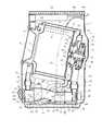
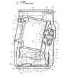
まず、図1には、洗濯乾燥機、中でもドラム式(横軸形)洗濯乾燥機の全体構成を示しており、外殻である外箱1の内部に、水槽2を配設し、水槽2の内部に回転槽(ドラム)3を配設している。Hereinafter, the present invention is applied to a washing and drying machine, and a first example (first embodiment) will be described with reference to FIGS.
First, FIG. 1 shows the overall structure of a washing / drying machine, especially a drum type (horizontal axis) washing / drying machine. A
上記水槽2及び回転槽3は、ともに円筒状を成すもので、前側(図中、左側)の端面部にそれぞれの開口部4,5を有している。このうち、回転槽3の開口部5は洗濯物(衣類)出し入れ用であり、それを水槽2の開口部4が囲繞している。又、水槽2の開口部4は、外箱1の前面部に形成した洗濯物出し入れ用の開口部6にベローズ7で連ねており、外箱1の開口部6には扉8を開閉可能に設けている。 The
回転槽3には又、周側部(胴部)のほゞ全域に孔9を形成しており(一部のみ図示)、この孔9は、洗濯時及び脱水時における通水孔として機能すると共に乾燥時における通風孔としても機能するようになっている。水槽2には、前側の端面部の上部(前記開口部4より上方の部分)に温風出口10を形成し、後側の端面部の上部に温風入口11を形成している。このほか、水槽2の底部の最後部には、排水口12を形成しており、この排水口12に水槽2外で排水弁13を接続し、更に、排水弁13に排水ホース14を接続して、これらにより水槽2内の水を機外に排出するようにしている。 The
回転槽3の後側の端面部の後面(背面)には、補強部材15を取付けており、この補強部材15を介して、回転槽3の後側の端面部の中心部に回転軸16を取付け、該回転軸16を補強部材15から後方へ突出させている。回転槽3の後側の端面部の中心部周りには、多数の小孔から成る温風導入口17を形成している。 A reinforcing
これに対して、水槽2の後側の端面部の後面の中心部には、軸受ハウジング18を取付けており、この軸受ハウジング18の中心部に上記回転軸16を挿通して軸受19,20により回転可能に支承している。又、それにより、回転槽3を水槽2に同軸状で回転可能に支持している。なお、水槽2は、図示しないサスペンションにより前記外箱1に弾性支持しており、その支持形態は、水槽2の軸方向が前後となる横軸状で、しかも前上がりの傾斜状であり、従って、この水槽2に上述のように支持された回転槽3も、同形態となっている。 On the other hand, a
前記軸受ハウジング18には、外周に、モータ21のステータ22を取付けており、このステータ22に、回転軸16の後端部に取付けたロータ23を外側から対向させている。従って、モータ21はアウターロータ形であり、更に、この場合、ブラシレスDCモータであって、回転槽3を回転軸16を中心に回転させる駆動装置として機能するようになっている。 A
水槽2の後側の端面部の内側には、温風カバー24を装着している。この温風カバー24は、下部に開口部25を有し、この開口部25によって前記回転軸16を囲繞している。又、温風カバー24は、開口部25の部分より上方の部分にて前記温風入口11に対向し、該温風入口11を覆っている。更に、温風カバー24の全体として、水槽2の後側の端面部との間に、前記回転槽3の後側の端面部と水槽2の後側の端面部との間の空間の例えば1/3程度の空間を隔てており、その空間によって、上記温風入口11から回転軸16の周囲部分へと通じる温風通路26を構成している。なお、温風カバー24の開口部25は回転軸16より充分径大で、温風通路26の出口部に相当するようになっている。 A
前記補強部材15には、前記回転軸16を取付けた中心部の周囲部分に複数の比較的大きな孔27を形成しており、これが上記温風カバー24の開口部25(温風通路26の出口部)と前記回転槽3の温風導入口17との間にあって、それらを連通させることにより、温風導入路28を構成している。 The reinforcing
前記補強部材15には又、上記温風導入路28を構成した部分の周囲部のうちの後側にシール部材29を装着している。シール部材29は、合成ゴム等の弾性材から成っており、前記温風カバー24の開口部25周囲の部分に当接し、摺接するようになっている。この結果、シール部材29は、回転槽3と水槽2との間において、温風導入路28と温風通路26との間をシールするようになっている。 The reinforcing
水槽2の下方(外箱1の底面上)には、複数個のクッション30を介して台板31を配置し、この台板31上に通風ダクト32を配置している。この通風ダクト32は、前端部の上部に吸風口33を有しており、この吸風口33に、前記水槽2の温風出口10を還風ダクト34及び接続ホース35を介して接続している。なお、還風ダクト34は前記ベローズ7の左側を迂回するように配管している。 A
一方、通風ダクト32の後端部には循環用送風機36のケーシング37を接続しており、このケーシング37の出口部38を、接続ホース39及び給風ダクト40を介して、前記水槽2の温風入口11に接続している。なお、給風ダクト40は前記モータ21の左側を迂回するように配管している。 On the other hand, a
これらの結果、還風ダクト34、接続ホース35、通風ダクト32、ケーシング37、接続ホース39、給風ダクト40により、前記水槽2の温風出口10と温風入口11とを接続して通風路41が設けられている。
なお、前記循環用送風機36は、ケーシング37の内部に送風ファン42を有しており、この送風ファン42を回転させるモータ43をケーシング37の外部に有している。As a result, the
The
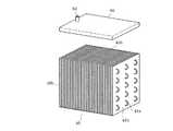
しかして、通風路41中、通風ダクト32の内部には、前部に蒸発器44を配置しており、従って、洗濯乾燥機全体の前側に蒸発器44を配置していて、後部に凝縮器45を配置している。凝縮器45は、詳細には図3に示すように、蛇行状に曲成した冷媒流通パイプ45aに伝熱フィン45bを多数取着して成るもので、蒸発器44も、図示はしないが同様の構成である。又、それらの伝熱フィンの向きは通風ダクト32を後述のように通る風の流れと平行で、要するにそのフィン間を通風させるようになっている。 Thus, in the
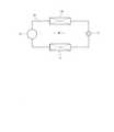
そして更に、それらの蒸発器44及び凝縮器45は、図2に示す圧縮機46及び絞り弁(特には電子式の絞り弁)47と共にヒートポンプ48を構成するもので、このヒートポンプ48においては、冷媒流通パイプ49によって、圧縮機46、凝縮器45、絞り弁47、蒸発器44の順にこれらをサイクル接続しており(冷凍サイクル)、圧縮機46が作動することによって冷媒を循環させるようになっている。なお、圧縮機46は、図1に示すように、通風ダクト32外に並設している。 Further, the
通風ダクト32の側面部中、前記吸風口33と蒸発器44との間における通風ダクト32底面部の最低部32aに臨む部分には、除湿水排出口50を形成している。この除湿水排出口50は、前記外箱1の側面下部に形成した排水口51に接続パイプ52によって接続しており、排水口51には又、通風ダクト32の底面部中、凝縮器45の直前部分に形成した冷却水排出口53を、接続パイプ54によって接続している。なお、通風ダクト32は、底面部中の、蒸発器44の直下に位置する部分32bを上記除湿水排出口50に向け下降する傾斜面とし、蒸発器44の直後に位置する部分32cを冷却水排出口53に向け下降する傾斜面としている。 A dehumidified
更に、前記通風路41における前記回転槽3と前記蒸発器44との間の部分である通風ダクト32の前端部から、機外である前方へは、吐出風路55を設けている。この吐出風路55は通風ダクト32と連通しており、その連通部分には、ダンパ56を設けている。このダンパ56は、図示を省略したモータや電磁石など駆動源の動力にて吐出風路55側の一端部である上端部を中心に回動することにより、上記通風ダクト32の前端部(通風路41における前記回転槽3と前記蒸発器44との間の部分)の遮断、開放の切換えをし、同時に吐出風路55の開放、遮断の切換えをする風路切換装置として機能するようになっている。 Further, a
又、吐出風路55の内部には、吐出用送風機57を設けており、それより前方の吐出風路55の出口部は斜め上方を指向していて、内部に同方向に傾斜するルーバ58を有している。 In addition, a
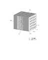
一方、通風路41における蒸発器44と凝縮器45との間の部分である通風ダクト32の中間部上壁には、空気導入口59を形成しており、凝縮器45に対しては、冷却装置60を設けている。この冷却装置60は、この場合、図3に示すように、凝縮器45上に載置した四角形の扁平容器から成っており、凝縮器45と接する側の下壁部に図4に示す散水孔61をほゞ全面にわたり多数有しており、上壁部の一端部に注水受口62を有していて、この注水受口62に図2に示す注水チューブ63の先端部を接続している。 On the other hand, an
しかして、注水チューブ63の基端部は、前記外箱1内の後上部に取付けた給水弁64の出口部の一つに接続している。なお、給水弁64は、注水チューブ63の基端部を接続した出口部のほかにも、出口部を複数有するもので、それらは前記外箱1内の前側の上部に配置した給水ボックス65に接続パイプ66によって接続している。更に、給水ボックス65は、詳しくは図示しないが、洗剤投入部並びに柔軟仕上剤投入部を有していて、上記給水弁64は、出口部の開放の選択により、洗い時に給水ボックス65の洗剤投入部を経て前記水槽2内に給水し、最終すすぎ時に給水ボックス65の柔軟仕上剤投入部を経て同じく水槽2内に給水し、そして、洗濯乾燥機が設置されたスペースの冷房をするときに、注水チューブ63を経て冷却装置60に注水するようにしている。
このほか、外箱1の背面部の下部には、外気吸込口67を形成している。Thus, the proximal end portion of the
In addition, an outside
次に、上記構成の洗濯乾燥機の作用を述べる。
上記構成の洗濯乾燥機では、標準的な運転コースが開始されると、最初に洗濯(洗い及びすすぎ)運転が開始される。この洗濯運転では、給水弁64にて水槽2内に給水する動作が行われ、続いて、モータ21が作動されることにより、回転槽3が低速で正逆両方向に交互に回転される。
洗濯運転が終了すると、次に、脱水運転が開始される。この脱水運転では、水槽2内の水を排出した後、回転槽3を高速で一方向に回転させる動作が行われる。これにより、回転槽3内の洗濯物(衣類)は遠心脱水される。Next, the operation of the washing / drying machine having the above configuration will be described.
In the washing and drying machine having the above configuration, when a standard operation course is started, a washing (washing and rinsing) operation is started first. In this washing operation, an operation of supplying water into the
When the washing operation is completed, the dehydration operation is then started. In this dehydration operation, after the water in the
脱水運転が終了すると、次に、乾燥運転が実行される。この乾燥運転では、ダンパ56が、通風ダクト32の前端部(通風路41における回転槽3と蒸発器44との間の部分)の開放をし、吐出風路55の遮断をするようにセットされる。この状態で、回転槽3を低速で正逆両方向に回転させつつ、循環用送風機36のモータ43を作動させる。すると、送風ファン42の送風作用で、図1に矢印で示すように、水槽2内の空気が温風出口10から通風路41の還風ダクト34及び接続ホース35を経て通風ダクト32内に流入される。 When the dehydration operation is completed, a drying operation is next performed. In this drying operation, the
又、このときには、ヒートポンプ48の圧縮機46の作動が開始される。これにより、ヒートポンプ48に封入した冷媒が圧縮されて高温高圧の冷媒となり、その高温高圧の冷媒が凝縮器45に流れて、通風ダクト32内の空気と熱交換する。その結果、通風ダクト32内の空気が加熱され、反対に、冷媒の温度は低下して液化される。この液化された冷媒が、次に、絞り弁47を通過して減圧された後、蒸発器44に流入し、気化する。それにより、蒸発器44は通風ダクト32内の空気を冷却する。なお、蒸発器44を通過した冷媒は圧縮機46に戻る。 At this time, the operation of the
これらにより、前記水槽2内から通風ダクト32内に流入した空気は、蒸発器44で冷却されて除湿され、その後に凝縮器45で加熱されて温風化される。そして、その温風が接続ホース39、給風ダクト40を経て、温風入口11から水槽2内に供給され、更に、温風通路26、温風導入路28を経て、温風導入口17から回転槽3内に供給される。
回転槽3内に供給された温風は洗濯物の水分を奪った後、前記温風出口10から還風ダクト34及び接続ホース35を経て通風ダクト32内に流入する。As a result, the air that has flowed into the
The hot air supplied into the
かくして、蒸発器44と凝縮器45を有する通風ダクト32と回転槽3との間を空気が循環することにより、回転槽3内の洗濯物が乾燥される。なお、この乾燥運転中、蒸発器44では、前述の通風ダクト32内を通る空気の冷却除湿が行われることに伴い、表面に結露が生じ、その露が蒸発器44から滴下して直下の通風ダクト32における傾斜面32bを流下し、除湿水排出口50から接続パイプ52及び排水口51を通って機外に排出される。 Thus, air circulates between the
以上に対して、洗濯乾燥機が設置されたスペースの冷房を行うときには、図5に示すように、ダンパ56が、通風ダクト32の前端部(通風路41における回転槽3と蒸発器44との間の部分)の遮断をし、吐出風路55の開放をするように切換えられ、この状態で、ヒートポンプ48の圧縮機46の作動が開始されると共に、吐出用送風機57が作動される。 In contrast, when the space where the washing and drying machine is installed is cooled, as shown in FIG. 5, the
これらにより、図5に実線矢印で示すように、通風ダクト32外の空気が空気導入口59から通風ダクト32内に吸入されて蒸発器44を通り冷却される。そして、その冷却された空気が吐出風路55を通って機外の前方に吐出され、洗濯乾燥機が設置されたスペースの冷房を行う。なお、これに伴って、外箱1の外気吸込口67からは、機外の空気が外箱1内(通風ダクト32外)に吸い込まれる。 As a result, as indicated by solid arrows in FIG. 5, the air outside the
又、このときには、図5に破線矢印で示すように、給水弁64から注水チューブ63を経て凝縮器45上の冷却装置60に注水がなされるものであり、従って、冷却装置60の散水孔61からは、凝縮器45に散水がなされ、かくして凝縮器45が冷却、特には水によって冷却される。すなわち、凝縮器45からは、蒸発器44で空気を冷却する際に吸収した熱エネルギーと、圧縮機46の仕事によって加わった熱エネルギーとが、冷却媒体(この場合、水)に放出されるものであり、もって、冷房システムとして実際に稼動し、洗濯乾燥機が設置されたスペースの冷房が所望にできる。 Further, at this time, as shown by a broken line arrow in FIG. 5, water is supplied from the
実験では、このときの凝縮器45の冷却に1〜1.5リットルの水を使用することで、床面積が4〔m2〕のスペースを約1時間で約10〔deg〕冷却することができており、冷房装置としての機能が確認できた。
なお、凝縮器45から上述の熱エネルギーを奪った水は、冷却水排出口53から接続パイプ54及び排水口51を通って機外に排出される。In the experiment, by using 1 to 1.5 liters of water for cooling the
The water deprived of the heat energy from the
又、このとき、凝縮器45は上述のように冷却されるが、それを通る空気の流れを積極的に遮断してはいない。しかし、乾燥運転時に凝縮器45を通る風路は、給風ダクト40等を介して回転槽3に繋がり、更に回転槽3から還風ダクト34に繋がっており、このような構成では、風路はほゞ密閉に近い。従って、冷房時に、還風ダクト34(通風路41における回転槽3と蒸発器44との間の部分)をダンパ56で塞ぐことにより、凝縮器45側の風路は実質的に塞がれることになり、蒸発器44と凝縮器45との間に空気導入口59が存していても、凝縮器45を通る空気流が実際には生じない。よって、ダンパ56はそれ1つを要するのみで冷房ができるという効果を有する。 At this time, the
又、通風ダクト32の空気導入口59を形成した部分は、循環用送風機36が生成する循環風の流れの風下側に位置するもので、負圧となる場所であり、そこで若干の圧力逃がしができることにより、むしろ乾燥運転時の蒸発器44における除湿をしやすくできるという効果がある。 The portion of the
このように本構成のものでは、ダンパ(風路切換装置)56を、吐出風路55を開放すると共に、通風路41における回転槽3と蒸発器44との間の部分を遮断するように切換え、ヒートポンプ48と吐出用送風機57及び冷却装置60を作動させることにより、凝縮器45を冷却装置60で冷却しつつ、空気導入口59から導入した通風路41外の空気を蒸発器44で冷却して吐出風路55から機外に吐出することにより、洗濯物(衣類)乾燥用のヒートポンプ48を利用しての、洗濯乾燥機が設置されたスペースの冷房が所望にできる。 As described above, in this configuration, the damper (air path switching device) 56 is switched so as to open the
加えて、本構成のものの場合、冷却装置60は凝縮器45を水により冷却するものとしており、要するに水冷方式で、冷却効果に優れるから、洗濯乾燥機が設置されたスペースの冷房もより効果的にできる。又、この場合、凝縮器45には冷却装置60に多数存する散水孔61から散水、すなわちシャワー状に散水するものであり、それによって、凝縮器45に広く水をかけて効果的に冷却することができ、従って、洗濯乾燥機が設置されたスペースの冷房も一段と効果的にできる。 In addition, in the case of this configuration, the
そして、更に本構成のものの場合、蒸発器44を、機全体の前側に配設している。これに対して、既述の特許文献1に記載のものでは、蒸発器が、凝縮器より後方で、機全体の後側に配置されている。このため、洗濯乾燥機が設置されたスペースを冷房する際の風路を、凝縮器を迂回して機外に連なる第2の風路(バイパス)として設ける必要がある。しかしながら、そのような第2の風路を設けることは、製品の容積などの理由から困難である。又、第2の風路を設け得たとしても、全体の風路が複雑になってしまう。特に本構成の方式で乾燥及び冷房を行うものにおいては、蒸発器44や凝縮器45は構造上空気の流れに対する抵抗が大きく、これに風路が複雑になることが加わると、風量を充分に出すことができなくなる。 Further, in the case of this configuration, the
それに対して、本構成では、上述のように、蒸発器44を機全体の前側に配置しており、蒸発器44は凝縮器45に対してもそれの前方に位置するから、凝縮器45を迂回して機外に連なる上記第2の風路を設ける必要がない。従って、製品の容積面で有利であるばかりでなく、風の流れとしても、通風ダクト32外の空気が通風ダクト32の蒸発器44と凝縮器45との間に設けた空気導入口59から入り、蒸発器44を通って前方の吹出風路55から機外に放出されることにより、風路の抵抗もなくなり、よって、風量を充分に確保し得、冷房性能を充分に出すことができる。 On the other hand, in this configuration, as described above, the
又、本構成のものの場合、吐出用送風機57を蒸発器44より前方に配置している。これに対して、既述の特許文献1に記載のものでは、吐出用送風機を蒸発器より後方に配置しており、空気循環路外の空気を上述の第2の風路に送り込む方式となっている。この方式では、多数のダンパを配置して風路を切換える必要が生じる。又、蒸発器が、ヒートポンプに一般的に用いられるフィン式のものにおいては、本来空気抵抗が大きく、ダンパによる密閉度を高めないと、所期の風の流れは作りにくい。それに対して、本構成では、上述のように、吐出用送風機57を蒸発器44より前方に配置しており、蒸発器44より効率良く空気を吸い込むことができる。又、ダンパ56も、前述のように、それ1つだけあれば、乾燥運転状態から冷房運転状態への切換えが可能になる。よって、非常に簡単な構造で、洗濯乾燥機が設置されたスペースの冷房ができる。 In the case of this configuration, the
以上に対して、図6ないし図10は本発明の第2ないし第6実施例(第2ないし第6の実施形態)を示すもので、それぞれ、第1実施例と同一の部分には同一の符号を付して説明を省略し、異なる部分についてのみ述べる。 6 to 10 show second to sixth examples (second to sixth embodiments) of the present invention, and the same parts as those of the first example are the same. A description will be omitted with reference numerals, and only different parts will be described.
[第2実施例]
図6に示す第2実施例においては、凝縮器45を冷却する冷却装置71を、前述の冷却装置60に代えて、凝縮器45、特にはそれの冷媒流通パイプ45aの左右並び列の各間に、通水パイプ72を冷媒流通パイプ45aと並行に通して配設することで構成している。そして、その通水パイプ72の基端部には、前述の注水チューブ63の先端部を接続し、この構成で、通水パイプ72に水を流して先端部から排出することにより、凝縮器45を、通水パイプ72に流す水によって、伝熱フィン45bを媒体として伝熱させ、冷却するようにしている。[Second Embodiment]
In the second embodiment shown in FIG. 6, the
このようにしても、凝縮器45を効果的に冷却することができて、洗濯乾燥機が設置されたスペースの冷房が効果的にできる。
なお、この場合、通水パイプ72は、先端部を排水口51に直接接続して排水するようにしても良い。Even if it does in this way, the
In this case, the
[第3実施例]
図7に示す第3実施例においては、凝縮器45を空気で冷却するようにしている。具体的には、この場合、通風ダクト32の出口部38から空冷排気口81を分岐させて設け、これの先端部を外箱1の背面部から後方の機外に臨ませている。又、その空冷排気口81と通風ダクト32の出口部38との連通部分には、ダンパ82を設けており、このダンパ82は、図示を省略したモータや電磁石など駆動源の動力にて空冷排気口81側の一端部を中心に回動することにより、上記通風ダクト32の出口部38先端(通風路41における凝縮器45と回転槽3との間の部分)の遮断、開放の切換えをし、同時に空冷排気口81の開放、遮断の切換えをする第2の風路切換装置として機能するようになっている(この場合、前記ダンパ56は第1の風路切換装置として機能する)。[Third embodiment]
In the third embodiment shown in FIG. 7, the
この構成で、洗濯乾燥機が設置されたスペースの冷房を行うときには、図示のごとく、ダンパ56が前述のように切換えられ、ヒートポンプ48の圧縮機46と、吐出用送風機57とが作動されると共に、ダンパ82が通風ダクト32の出口部38先端の遮断をし、空冷排気口81の開放をするように切換えられ、そして、循環用送風機36が作動される。 In this configuration, when the space where the washing and drying machine is installed is cooled, the
すると、前述のように、通風ダクト32外の空気が空気導入口59から通風ダクト32内に吸入されて蒸発器44を通り、冷却されて吐出風路55から機外の前方に吐出されると共に、通風ダクト32外の空気が空気導入口59から凝縮器45を通り、それの熱を奪って、すなわち凝縮器45の冷却をして、空冷排気口81から機外に放出される。従って、このものの場合には、循環用送風機36が凝縮器45を冷却、特には空気により冷却(空冷)する冷却装置として機能する。 Then, as described above, the air outside the
又、この場合、循環用送風機36は、モータ43に電子制御モータを採用しており、その発生風量は回転速度を制御することで変化させ得るものであって、この冷房を行うには、乾燥運転を行うときの約半分程度の風量を発生することで、凝縮器45を冷却する目的を達することができる。 In this case, the
更に、この場合、空冷排気口81から機外に放出される空気は温風化しており、その温風は、圧縮機46を駆動した分、冷房の冷やす能力よりエネルギー的に大きくなる。このため、洗濯乾燥機が設置されたスペースの全体としては、徐々に加熱される方向にある。しかし、吐出風路55からは、洗濯乾燥機が設置されたスペースの室温よりも約10〔deg〕程度低い冷風が出るので、使用者はそれを浴びて爽快感を感じることができる。 Further, in this case, the air discharged from the air-cooled
かくして、この場合も、洗濯物乾燥用のヒートポンプ48を利用しての、洗濯乾燥機が設置されたスペースの冷房が所望にできる。
なお、このように凝縮器45を空気で冷却するには、循環用送風機36を利用するものに限られず、別にそれ専用の送風機を設けても良い。Thus, in this case as well, it is possible to cool the space where the washing / drying machine is installed by using the
In addition, in order to cool the
[第4実施例]
図8に示す第4実施例においては、上記第3実施例のものおいて、更に、通風ダクト32内の空気導入口59下方の位置に、仕切ダンパ91を起伏可能に設け、洗濯乾燥機が設置されたスペースの冷房を行うときに、その仕切ダンパ91を起立させることにより、空気導入口59から導入された通風ダクト32外の空気を、蒸発器44側と凝縮器45側とに振り分けるようにしている。
このようにすることで、蒸発器44による機外空気の冷却、並びに機外空気による凝縮機の冷却がそれぞれ効果にできるようになる。[Fourth embodiment]
In the fourth embodiment shown in FIG. 8, in the third embodiment, a
By doing so, cooling of the outside air by the
[第5実施例]
図9に示す第5実施例においては、空気導入口59から導入された通風ダクト32外の空気が蒸発器44を経てから機外に放出するまでの部分である吐出風路55内に、ヒータ(特には電気ヒータ)101を設けている。[Fifth embodiment]
In the fifth embodiment shown in FIG. 9, the heater outside the
ヒートポンプ48は、冷媒の流路を切換えることにより、冷媒が蒸発器44から絞り弁47を経て凝縮器45に流れるようにすれば、蒸発器44を凝縮器とし、凝縮器45を蒸発器として、洗濯乾燥機が設置されたスペースに温風を放出し、暖房することが基本的に可能である。しかしながら、その場合、凝縮器(蒸発器44)で加熱をするためのエネルギーを蒸発器(凝縮器45)に外部から与える必要がある。本構成のもので、凝縮器45がそれに外部より与えられる水からエネルギーを吸収することは可能であるが、洗濯乾燥機が設置されたスペースを暖房するほどのエネルギーを吸収することは困難である。 If the refrigerant flows from the
冷房については、例えば床面積が4〔m2〕程度のスペースを10〔deg〕程度冷房する場合、圧縮機46の能力は1.2〔kWh〕程度必要である。これは、床面積1〔m2〕について200W程度を要するとして、上記4〔m2〕程度の面積では、800〔Wh〕程度必要であるものの、圧縮機が機外に設置されるエアコンディショナーと違い、本構成のものの圧縮機46は室内にあり、その分のエネルギーを余分に吸収する必要があるためである。このため、圧縮機46の駆動入力を400Whとして、1.2〔kWh〕程度の冷凍能力が必要になるのである。このエネルギーを毎分1.0リットル程度の水で放出するためには、理論的に17〔deg〕程度の温度上昇をすることになる。従って、夏場の水温が20〔℃〕程度として、約40〔℃〕弱の温水を排出することで冷房が可能となる。As for cooling, for example, when a space having a floor area of about 4 [m2 ] is cooled by about 10 [deg], the capacity of the
一方、暖房については、室温が5〔℃〕程度のスペースを20〔℃〕程度に昇温する必要があり、その15〔deg〕を温度上昇させるためには、上記800〔Wh〕の1.5倍の1.2〔kWh〕程度の能力が必要になる。しかし、この場合、冷房とは逆に、圧縮機46の駆動入力は、圧縮機46が室内に存する分を差し引き、800〔Wh〕程度のエネルギーを必要とするに留め得る。上述と同じく、毎分1.0リットルの水からこのエネルギーを吸収するためには、理論的に14.5〔deg〕程度水温を下げる必要があるが、冬場の水温は5℃程度と考えられるので、−10〔℃〕程度の温度の水が必要となってしまう。水は0〔℃〕で凍ってしまうため、それ以上はエネルギーを吸収することができない。従って、本構成のものでヒートポンプ48を使用しての暖房は実際上できない。 On the other hand, with regard to heating, it is necessary to raise the temperature of a room having a room temperature of about 5 [° C.] to about 20 [° C.]. The capacity of about 1.2 [kWh], which is five times, is required. However, in this case, contrary to cooling, the drive input of the
それに対して、この第5実施例では、空気導入口59から導入された通風ダクト32外の空気が蒸発器44を経てから機外に放出するまでの部分である吐出風路55内に、ヒータ(特には電気ヒータ)101を設けている。この場合、特には、吐出用送風機57への熱影響を考慮し、該吐出用送風機57より機外側にヒータ101を設けることが望ましい。 On the other hand, in the fifth embodiment, the heater outside the
このようにすることで、暖房時には、吐出用送風機57とヒータ101を作動させるのみで、空気導入口59から導入した通風ダクト32外の空気をヒータ101で温風化して機外に放出し、ヒートポンプ48を作動させずに、洗濯乾燥機が設置されたスペースの暖房が可能となる。
なお、この場合、凝縮器45の冷却は第1実施例の冷却装置60でするようにしているが、それに代え、第2実施例の冷却装置71でするようにしても良く、更には第3、第4実施例方式にて循環用送風機36でするようにしても良い。By doing in this way, at the time of heating, only the
In this case, the cooling of the
[第6実施例]
図10に示す第6実施例においては、吐出風路111を、前述の吐出風路55に代えて、機全体の上部に設けている。具体的には、水槽2の温風出口10と対向する還風ダクト34の上部から機外である前方に、吐出風路111を設けている。従って、この吐出風路111は、還風ダクト34と連通しており、その連通部分に、ダンパ112を設けている。このダンパ112、図示を省略したモータや電磁石など駆動源の動力にて吐出風路111側の一端部である上端部を中心に回動することにより、上記還風ダクト34の上部(通風路41における回転槽3と蒸発器44との間の部分)の遮断、開放の切換えをし、同時に吐出風路111の開放、遮断の切換えをする風路切換装置として機能するようになっており、要するに前述のダンパ56と同様に機能するものである。[Sixth embodiment]
In the sixth embodiment shown in FIG. 10, the
又、この場合、吐出用送風機57は、ヒータ101とともに、吐出風路111の内部に設けており、それらより前方の吐出風路111の出口部に、斜め上方に傾斜するルーバ113を設けている。 Further, in this case, the
従って、この場合、冷房時の冷風及び暖房時の温風は、機全体の上部から放出されることになり、使用者が冷風による爽快感や温風による暖かさを、スペースの温度の変化以上に直接的に感じることができると共に、それらの効果を出すのに必要な時間も大幅に短縮することができる。
なお、この場合も、凝縮器45の冷却は第1実施例の冷却装置60でするようにしているが、それに代え、第2実施例の冷却装置71でするようにしても良く、更には第3、第4実施例方式にて循環用送風機36でするようにしても良い。Therefore, in this case, the cool air during cooling and the warm air during heating are discharged from the upper part of the entire machine, and the user feels the refreshing feeling due to the cool air and the warmth due to the warm air more than the change in the temperature of the space. The time required to produce these effects can be greatly reduced.
In this case as well, the
このほか、本発明は上記し且つ図面に示した実施例にのみ限定されるものではなく、特に洗濯乾燥機全体としては、上述の横軸形に限られず、水槽及び回転槽を横軸状に有する横軸形であっても良いし、又、本来的には洗濯と乾燥の両機能を有する洗濯乾燥機に限られず、乾燥機能のみを有する衣類乾燥機にも適用できるなど、要旨を逸脱しない範囲内で適宜変更して実施し得る。 In addition, the present invention is not limited only to the embodiment described above and shown in the drawings. In particular, the entire washing / drying machine is not limited to the above-described horizontal axis shape, and the water tank and the rotating tank are formed in a horizontal axis shape. It does not depart from the gist of the present invention, such as being applicable to a clothes dryer having only a drying function. It can be carried out with appropriate modifications within the range.
図面中、3は回転槽、21はモータ(駆動装置)、36は循環用送風機(冷却装置)、41は通風路、44は蒸発器、45は凝縮器、46は圧縮機、48はヒートポンプ、55は吐出風路、56はダンパ(風路切換装置)、57は吐出用送風機、59は空気導入口、60,71は冷却装置、72は通水パイプ、111は吐出風路、112はダンパ(風路切換装置)を示す。 In the drawings, 3 is a rotating tank, 21 is a motor (drive device), 36 is a circulation fan (cooling device), 41 is a ventilation path, 44 is an evaporator, 45 is a condenser, 46 is a compressor, 48 is a heat pump, 55 is a discharge air path, 56 is a damper (air path switching device), 57 is a blower for discharge, 59 is an air inlet, 60 and 71 are cooling devices, 72 is a water flow pipe, 111 is a discharge air path, and 112 is a damper. (Airway switching device) is shown.
Claims (5)
Translated fromJapanese前記通風路の前記回転槽と蒸発器との間の部分から機外に通じるように設けた吐出風路と、
前記乾燥運転を行うときには前記吐出風路を遮断し、この状態からその吐出風路を開放すると共に、前記通風路の前記回転槽と蒸発器との間の部分を遮断するように切換えられる風路切換装置と、
前記通風路の前記蒸発器と凝縮器との間の部分に設けた空気導入口と、
この空気導入口から通風路外の空気を導入して、それを前記蒸発器を通し、開放された前記吐出風路から機外に吐出する吐出用送風機と、
前記凝縮器を冷却する冷却装置とを具備して成ることを特徴とする衣類乾燥機。A rotating tank, a ventilation path, a driving device for rotating the rotating tank, a circulation fan for circulating the air in the rotation tank through the ventilation path, and an evaporator and a condenser in the ventilation path In which a heat pump configured by cycle-connecting them with a compressor and performing a drying operation for drying clothes,
A discharge air passage provided so as to communicate with the outside from the portion between the rotary tank and the evaporator of the air passage;
When the drying operation is performed, the discharge air passage is shut off, and the discharge air passage is opened from this state, and the air passage is switched to shut off the portion of the ventilation passage between the rotary tank and the evaporator. A switching device;
An air inlet provided in a portion of the ventilation path between the evaporator and the condenser;
A blower for discharge that introduces air outside the ventilation path from this air introduction port, passes it through the evaporator, and discharges it outside the discharge air path,
A clothes dryer comprising a cooling device for cooling the condenser.
2. The clothes dryer according to claim 1, wherein a discharge air passage is provided at an upper portion of the entire machine.
Priority Applications (7)
| Application Number | Priority Date | Filing Date | Title |
|---|---|---|---|
| JP2005333011AJP4783125B2 (en) | 2005-11-17 | 2005-11-17 | Clothes dryer |
| TW095121275ATW200720506A (en) | 2005-11-17 | 2006-06-14 | Clothes dryer |
| PCT/JP2006/322570WO2007058145A1 (en) | 2005-11-17 | 2006-11-13 | Clothes dryer |
| CN2006800429044ACN101310068B (en) | 2005-11-17 | 2006-11-13 | Clothes dryer |
| US12/094,056US7866061B2 (en) | 2005-11-17 | 2006-11-13 | Clothes dryer |
| KR1020087011197AKR100986910B1 (en) | 2005-11-17 | 2006-11-13 | Clothes dryer |
| EP06823344AEP1961853A4 (en) | 2005-11-17 | 2006-11-13 | Clothes dryer |
Applications Claiming Priority (1)
| Application Number | Priority Date | Filing Date | Title |
|---|---|---|---|
| JP2005333011AJP4783125B2 (en) | 2005-11-17 | 2005-11-17 | Clothes dryer |
Publications (2)
| Publication Number | Publication Date |
|---|---|
| JP2007135832Atrue JP2007135832A (en) | 2007-06-07 |
| JP4783125B2 JP4783125B2 (en) | 2011-09-28 |
Family
ID=38048531
Family Applications (1)
| Application Number | Title | Priority Date | Filing Date |
|---|---|---|---|
| JP2005333011AExpired - Fee RelatedJP4783125B2 (en) | 2005-11-17 | 2005-11-17 | Clothes dryer |
Country Status (7)
| Country | Link |
|---|---|
| US (1) | US7866061B2 (en) |
| EP (1) | EP1961853A4 (en) |
| JP (1) | JP4783125B2 (en) |
| KR (1) | KR100986910B1 (en) |
| CN (1) | CN101310068B (en) |
| TW (1) | TW200720506A (en) |
| WO (1) | WO2007058145A1 (en) |
Cited By (4)
| Publication number | Priority date | Publication date | Assignee | Title |
|---|---|---|---|---|
| JP2009017936A (en)* | 2007-07-10 | 2009-01-29 | Toshiba Corp | Washing and drying machine |
| JP2009065995A (en)* | 2007-09-10 | 2009-04-02 | Toshiba Corp | Washing machine |
| JP2009066398A (en)* | 2007-09-13 | 2009-04-02 | Lg Electronics Inc | Ductless dryer |
| US20100126032A1 (en)* | 2007-02-13 | 2010-05-27 | Lg Electronics Inc. | Ductless dryer |
Families Citing this family (56)
| Publication number | Priority date | Publication date | Assignee | Title |
|---|---|---|---|---|
| JP4521297B2 (en)* | 2005-02-22 | 2010-08-11 | 株式会社東芝 | Drum type washer / dryer |
| DE102005013051A1 (en)* | 2005-03-18 | 2006-09-21 | BSH Bosch und Siemens Hausgeräte GmbH | Condensation Dryer |
| DE102005013053A1 (en)* | 2005-05-23 | 2006-11-30 | BSH Bosch und Siemens Hausgeräte GmbH | Condensation Dryer |
| JP4880982B2 (en)* | 2005-11-18 | 2012-02-22 | 株式会社東芝 | Washing and drying machine |
| JP4679352B2 (en)* | 2005-11-25 | 2011-04-27 | 株式会社東芝 | Clothes dryer |
| AU2008213226B2 (en)* | 2007-02-08 | 2011-08-25 | Lg Electronics Inc. | Hot air generating apparatus and dryer having the same |
| WO2009031812A2 (en)* | 2007-09-04 | 2009-03-12 | Lg Electronics Inc. | Dehumidifying apparatus for dryer |
| KR100925738B1 (en)* | 2007-09-04 | 2009-11-11 | 엘지전자 주식회사 | Drying temperature and humidity control device |
| ITVE20070080A1 (en)* | 2007-10-25 | 2009-04-26 | Piovan Spa | INFRARED DEHUMIDIFIER |
| DE102007052079A1 (en)* | 2007-10-31 | 2009-05-07 | BSH Bosch und Siemens Hausgeräte GmbH | Exhaust air dryer with heat recovery and condensate tray and process for its operation |
| DE102007052839A1 (en)* | 2007-11-06 | 2009-05-07 | BSH Bosch und Siemens Hausgeräte GmbH | Dryer with heat pump circuit |
| WO2009074455A1 (en)* | 2007-12-11 | 2009-06-18 | BSH Bosch und Siemens Hausgeräte GmbH | Household appliance comprising a first air conduit and a heat pump |
| DE102007061041A1 (en)* | 2007-12-18 | 2009-06-25 | BSH Bosch und Siemens Hausgeräte GmbH | Clothes drying machine with a heat pump |
| ITPN20080015A1 (en)* | 2008-02-27 | 2009-08-28 | Imat Spa | "HEAT PUMP LINEN DRYING MACHINE" |
| ITBO20080716A1 (en)* | 2008-11-28 | 2010-05-29 | Rivacold S R L | DEVICE FOR STEAM CONDENSATION AND ENERGY RECOVERY |
| DE102008044277A1 (en)* | 2008-12-02 | 2010-06-10 | BSH Bosch und Siemens Hausgeräte GmbH | Dryer with a heat pump and an electric heater and method of operation |
| DE102008044323A1 (en)* | 2008-12-03 | 2010-06-10 | BSH Bosch und Siemens Hausgeräte GmbH | Condensation dryer with a housing |
| US8490438B2 (en)* | 2009-02-05 | 2013-07-23 | Lg Electronics Inc. | Laundry treatment device |
| KR101542389B1 (en) | 2009-02-05 | 2015-08-06 | 엘지전자 주식회사 | A Heat Pump Module and A Drying Machine having the heat pump module |
| CN102292489B (en)* | 2009-02-23 | 2013-05-01 | Lg电子株式会社 | Washing machine |
| EP2398948B1 (en) | 2009-02-23 | 2018-09-12 | LG Electronics Inc. | Washing machine |
| KR101603106B1 (en) | 2009-03-03 | 2016-03-14 | 엘지전자 주식회사 | Washing machine |
| JP5443119B2 (en)* | 2009-10-16 | 2014-03-19 | パナソニック株式会社 | Clothes dryer and washing dryer |
| PL2314757T3 (en)* | 2009-10-20 | 2015-10-30 | Candy Spa | Household appliance with improved condenser cooling system |
| TWI381077B (en)* | 2009-10-22 | 2013-01-01 | Ind Tech Res Inst | Heat pump clothes dryer and controlling method for heat pump clothes dryer |
| CN102094309A (en)* | 2009-12-11 | 2011-06-15 | 博西华电器(江苏)有限公司 | Clothes treatment equipment with drying function and control method thereof |
| RU2507328C1 (en)* | 2010-04-28 | 2014-02-20 | ЭлДжи ЭЛЕКТРОНИКС ИНК. | Device for laundry processing |
| US8650770B1 (en) | 2010-06-17 | 2014-02-18 | George Samuel Levy | Air cycle heat pump dryer |
| CN102337665B (en)* | 2010-07-16 | 2013-03-06 | 田飞 | Drying machine with heat recovery device |
| US8528227B2 (en) | 2010-07-26 | 2013-09-10 | General Electric Company | Apparatus and method for refrigerant cycle capacity acceleration |
| US8601717B2 (en) | 2010-07-26 | 2013-12-10 | General Electric Company | Apparatus and method for refrigeration cycle capacity enhancement |
| US8353114B2 (en)* | 2010-07-26 | 2013-01-15 | General Electric Company | Apparatus and method for refrigeration cycle with auxiliary heating |
| EP2479337B1 (en)* | 2011-01-24 | 2013-08-07 | Electrolux Home Products Corporation N.V. | Household appliance for drying objects |
| CN103547728B (en)* | 2011-03-29 | 2016-03-23 | Lg电子株式会社 | There is the device for clothing processing of heat exchanger cleaning device |
| CN102277712B (en)* | 2011-07-26 | 2016-06-01 | 海尔集团公司 | A kind of dryer with front and back air-exhausting function |
| CN102330316B (en)* | 2011-08-12 | 2016-06-01 | 佛山海尔滚筒洗衣机有限公司 | A kind of have the double; two washing-drying integral machines drying air inlets in front and back and control method |
| CN103103735B (en)* | 2011-11-15 | 2016-04-27 | 上海申光洗涤机械集团有限公司 | Negative-pressure front gate inlet air dryer |
| KR101989522B1 (en)* | 2012-10-22 | 2019-09-30 | 엘지전자 주식회사 | A clothes dryer |
| US9091015B2 (en) | 2012-11-28 | 2015-07-28 | Elwha Llc | Energy efficient dryer systems |
| US8973286B1 (en) | 2014-01-27 | 2015-03-10 | Elwha Llc | Vacuum assisted dryer systems and methods |
| CN104452176A (en)* | 2014-11-06 | 2015-03-25 | 珠海格力电器股份有限公司 | Washing and drying integrated machine |
| KR101613966B1 (en) | 2014-12-29 | 2016-04-20 | 엘지전자 주식회사 | Clothes treating apparatus |
| KR101638923B1 (en) | 2015-01-13 | 2016-07-12 | 엘지전자 주식회사 | drying machine |
| DE102015216433A1 (en)* | 2015-08-27 | 2017-03-02 | BSH Hausgeräte GmbH | Household appliance with cleaning device for heat exchangers |
| KR102585025B1 (en) | 2016-01-05 | 2023-10-05 | 엘지전자 주식회사 | Clothes treatment apparatus having the heat pump module |
| CN107543251B (en)* | 2017-09-19 | 2019-10-01 | 青岛海尔空调器有限总公司 | Indoor unit |
| CN107687676B (en)* | 2017-09-19 | 2019-11-05 | 青岛海尔空调器有限总公司 | Indoor unit |
| EP3467187B1 (en) | 2017-10-09 | 2021-12-22 | Whirlpool Corporation | Filter configured for being used in a machine for drying laundry and machine for drying laundry equipped with such a filter |
| CN109944045B (en)* | 2019-02-19 | 2022-06-17 | 青岛胶州海尔洗涤电器有限公司 | Air exhaust structure and lint cleaning method of clothes drying equipment |
| KR20210009694A (en)* | 2019-07-17 | 2021-01-27 | 삼성전자주식회사 | Clothes care apparatus and control method thereof |
| CN116949777A (en)* | 2019-08-14 | 2023-10-27 | Lg电子株式会社 | Clothes dryer |
| KR102842499B1 (en)* | 2020-01-28 | 2025-08-06 | 삼성전자주식회사 | Clothes dryer |
| WO2022108151A1 (en)* | 2020-11-20 | 2022-05-27 | 삼성전자주식회사 | Dryer and method for controlling same |
| EP4039872A3 (en)* | 2021-02-08 | 2022-11-02 | LG Electronics Inc. | Laundry treating apparatus and method for controlling the same |
| US12378718B2 (en) | 2022-09-13 | 2025-08-05 | Samsung Electronics Co., Ltd. | Clothes care apparatus |
| US12428773B2 (en)* | 2022-10-18 | 2025-09-30 | Samsung Electronics Co., Ltd. | Clothes treating apparatus |
Citations (4)
| Publication number | Priority date | Publication date | Assignee | Title |
|---|---|---|---|---|
| JPH03103144A (en)* | 1989-09-14 | 1991-04-30 | Kanebo Ltd | Preparation of chocolate cake having plural kinds of pastry |
| JPH0956992A (en)* | 1995-08-29 | 1997-03-04 | Sharp Corp | Clothes dryer |
| JP2001183018A (en)* | 1999-12-28 | 2001-07-06 | Sanyo Electric Co Ltd | Air water cooling type condenser |
| JP2003265881A (en)* | 2002-03-19 | 2003-09-24 | Sanyo Electric Co Ltd | Washing/drying machine |
Family Cites Families (18)
| Publication number | Priority date | Publication date | Assignee | Title |
|---|---|---|---|---|
| US2280512A (en)* | 1940-05-02 | 1942-04-21 | B F Sturtevant Co | Refrigeration apparatus |
| US2755072A (en)* | 1954-07-12 | 1956-07-17 | Joseph W Kreuttner | Air conditioning |
| US2825146A (en)* | 1955-03-22 | 1958-03-04 | Westinghouse Electric Corp | Clothes drying apparatus |
| IT1155193B (en)* | 1982-05-10 | 1987-01-21 | Indesit | DRIER APPARATUS PARTICULARLY CLOTHES DRYER |
| JPH0377116A (en) | 1989-08-19 | 1991-04-02 | Mitsubishi Electric Corp | bus relay circuit |
| JPH0712815Y2 (en)* | 1989-11-27 | 1995-03-29 | オリオン機械株式会社 | Air dehumidifier |
| DE4023000C2 (en)* | 1990-07-19 | 2003-02-27 | Bsh Bosch Siemens Hausgeraete | Tumble dryer with a heat pump circuit |
| JPH04120552A (en) | 1990-09-11 | 1992-04-21 | Seiko Epson Corp | Toner for electrophotography and its manufacturing method |
| JPH04120552U (en)* | 1991-04-10 | 1992-10-28 | 株式会社富士通ゼネラル | Air conditioner control device |
| DE4211011C2 (en)* | 1992-04-02 | 1996-08-22 | Bosch Siemens Hausgeraete | Household clothes dryer with a process air duct and a heat exchanger |
| MY115384A (en) | 1994-12-06 | 2003-05-31 | Sharp Kk | Drum type washing machine and drier |
| EP1146161A1 (en)* | 2000-04-10 | 2001-10-17 | Whirlpool Corporation | Accessory assembly for a clothes drum type dryer |
| US6477854B2 (en) | 2000-09-08 | 2002-11-12 | Lg Electronics Inc. | Small air conditioner and dehumidifying device by using the same |
| JP2003111998A (en)* | 2001-10-09 | 2003-04-15 | Matsushita Electric Ind Co Ltd | Dryer |
| JP2004028356A (en)* | 2002-06-21 | 2004-01-29 | Hitachi Home & Life Solutions Inc | Heat pump water heater |
| JP2004116899A (en)* | 2002-09-26 | 2004-04-15 | Matsushita Electric Ind Co Ltd | Heat pump dryer |
| KR20050076213A (en)* | 2004-01-20 | 2005-07-26 | 삼성전자주식회사 | Clothing dryer |
| WO2005088003A1 (en)* | 2004-03-16 | 2005-09-22 | By For The Cleaners Co Ltd | Low-temperature humiditv eliminate drier |
- 2005
- 2005-11-17JPJP2005333011Apatent/JP4783125B2/ennot_activeExpired - Fee Related
- 2006
- 2006-06-14TWTW095121275Apatent/TW200720506A/ennot_activeIP Right Cessation
- 2006-11-13EPEP06823344Apatent/EP1961853A4/ennot_activeWithdrawn
- 2006-11-13WOPCT/JP2006/322570patent/WO2007058145A1/enactiveApplication Filing
- 2006-11-13USUS12/094,056patent/US7866061B2/ennot_activeExpired - Fee Related
- 2006-11-13KRKR1020087011197Apatent/KR100986910B1/ennot_activeExpired - Fee Related
- 2006-11-13CNCN2006800429044Apatent/CN101310068B/ennot_activeExpired - Fee Related
Patent Citations (4)
| Publication number | Priority date | Publication date | Assignee | Title |
|---|---|---|---|---|
| JPH03103144A (en)* | 1989-09-14 | 1991-04-30 | Kanebo Ltd | Preparation of chocolate cake having plural kinds of pastry |
| JPH0956992A (en)* | 1995-08-29 | 1997-03-04 | Sharp Corp | Clothes dryer |
| JP2001183018A (en)* | 1999-12-28 | 2001-07-06 | Sanyo Electric Co Ltd | Air water cooling type condenser |
| JP2003265881A (en)* | 2002-03-19 | 2003-09-24 | Sanyo Electric Co Ltd | Washing/drying machine |
Cited By (4)
| Publication number | Priority date | Publication date | Assignee | Title |
|---|---|---|---|---|
| US20100126032A1 (en)* | 2007-02-13 | 2010-05-27 | Lg Electronics Inc. | Ductless dryer |
| JP2009017936A (en)* | 2007-07-10 | 2009-01-29 | Toshiba Corp | Washing and drying machine |
| JP2009065995A (en)* | 2007-09-10 | 2009-04-02 | Toshiba Corp | Washing machine |
| JP2009066398A (en)* | 2007-09-13 | 2009-04-02 | Lg Electronics Inc | Ductless dryer |
Also Published As
| Publication number | Publication date |
|---|---|
| EP1961853A1 (en) | 2008-08-27 |
| CN101310068A (en) | 2008-11-19 |
| TWI352763B (en) | 2011-11-21 |
| US7866061B2 (en) | 2011-01-11 |
| TW200720506A (en) | 2007-06-01 |
| CN101310068B (en) | 2011-11-02 |
| US20090094852A1 (en) | 2009-04-16 |
| JP4783125B2 (en) | 2011-09-28 |
| KR20080056007A (en) | 2008-06-19 |
| EP1961853A4 (en) | 2011-06-22 |
| KR100986910B1 (en) | 2010-10-08 |
| WO2007058145A1 (en) | 2007-05-24 |
Similar Documents
| Publication | Publication Date | Title |
|---|---|---|
| JP4783125B2 (en) | Clothes dryer | |
| JP4550747B2 (en) | Clothes dryer | |
| JP4607774B2 (en) | Washing and drying machine | |
| JP4388088B2 (en) | Clothes dryer | |
| JP2007229377A (en) | Clothes dryer | |
| KR20090105080A (en) | Clothing processing device and control method | |
| JP2007319458A (en) | Washing and drying machine | |
| JP2003265880A (en) | Washing/drying machine | |
| JP2006141542A (en) | Drum type washer / dryer | |
| JP4791881B2 (en) | Clothes dryer | |
| JP2010088659A (en) | Washing/drying machine | |
| JP4795871B2 (en) | Clothes dryer | |
| JP2008284142A (en) | Clothes dryer | |
| JP2006075417A (en) | Drum type washer / dryer | |
| JP4791882B2 (en) | Clothes dryer | |
| JP2009240737A (en) | Cloth drier | |
| JP2009034188A (en) | Washing and drying machine | |
| JP2009034187A (en) | Washing and drying machine | |
| JP2005027734A (en) | Clothes dryer | |
| JP2005027733A (en) | Clothes dryer | |
| JP2009018088A (en) | Washing and drying machine | |
| JP4791880B2 (en) | Clothes dryer | |
| JP4828960B2 (en) | Clothes dryer | |
| JP2010194249A (en) | Washing/drying machine | |
| JP2003265881A (en) | Washing/drying machine |
Legal Events
| Date | Code | Title | Description |
|---|---|---|---|
| A621 | Written request for application examination | Free format text:JAPANESE INTERMEDIATE CODE: A621 Effective date:20080326 | |
| A131 | Notification of reasons for refusal | Free format text:JAPANESE INTERMEDIATE CODE: A131 Effective date:20100817 | |
| A521 | Request for written amendment filed | Free format text:JAPANESE INTERMEDIATE CODE: A523 Effective date:20101008 | |
| A131 | Notification of reasons for refusal | Free format text:JAPANESE INTERMEDIATE CODE: A131 Effective date:20110125 | |
| A521 | Request for written amendment filed | Free format text:JAPANESE INTERMEDIATE CODE: A523 Effective date:20110322 | |
| TRDD | Decision of grant or rejection written | ||
| A01 | Written decision to grant a patent or to grant a registration (utility model) | Free format text:JAPANESE INTERMEDIATE CODE: A01 Effective date:20110614 | |
| A01 | Written decision to grant a patent or to grant a registration (utility model) | Free format text:JAPANESE INTERMEDIATE CODE: A01 | |
| A61 | First payment of annual fees (during grant procedure) | Free format text:JAPANESE INTERMEDIATE CODE: A61 Effective date:20110708 | |
| FPAY | Renewal fee payment (event date is renewal date of database) | Free format text:PAYMENT UNTIL: 20140715 Year of fee payment:3 | |
| R150 | Certificate of patent or registration of utility model | Free format text:JAPANESE INTERMEDIATE CODE: R150 | |
| S111 | Request for change of ownership or part of ownership | Free format text:JAPANESE INTERMEDIATE CODE: R313117 Free format text:JAPANESE INTERMEDIATE CODE: R313115 | |
| S531 | Written request for registration of change of domicile | Free format text:JAPANESE INTERMEDIATE CODE: R313531 | |
| S533 | Written request for registration of change of name | Free format text:JAPANESE INTERMEDIATE CODE: R313533 | |
| R350 | Written notification of registration of transfer | Free format text:JAPANESE INTERMEDIATE CODE: R350 | |
| LAPS | Cancellation because of no payment of annual fees |