JP2007135148A - Folding mobile radio apparatus - Google Patents
Folding mobile radio apparatusDownload PDFInfo
- Publication number
- JP2007135148A JP2007135148AJP2005328701AJP2005328701AJP2007135148AJP 2007135148 AJP2007135148 AJP 2007135148AJP 2005328701 AJP2005328701 AJP 2005328701AJP 2005328701 AJP2005328701 AJP 2005328701AJP 2007135148 AJP2007135148 AJP 2007135148A
- Authority
- JP
- Japan
- Prior art keywords
- circuit board
- housing
- casing
- ground plate
- conductive material
- Prior art date
- Legal status (The legal status is an assumption and is not a legal conclusion. Google has not performed a legal analysis and makes no representation as to the accuracy of the status listed.)
- Granted
Links
- 239000012811non-conductive materialSubstances0.000claimsabstractdescription15
- 239000004020conductorSubstances0.000claimsdescription14
- 230000002411adverseEffects0.000abstractdescription2
- 239000002184metalSubstances0.000description6
- 238000010586diagramMethods0.000description4
- 230000005855radiationEffects0.000description3
- 230000001413cellular effectEffects0.000description2
- 230000008878couplingEffects0.000description2
- 238000010168coupling processMethods0.000description2
- 238000005859coupling reactionMethods0.000description2
- 230000000694effectsEffects0.000description2
- 239000010408filmSubstances0.000description2
- 239000000463materialSubstances0.000description2
- 239000012528membraneSubstances0.000description2
- 239000012789electroconductive filmSubstances0.000description1
- 238000000465mouldingMethods0.000description1
- 239000003973paintSubstances0.000description1
- 238000010422paintingMethods0.000description1
- 238000007747platingMethods0.000description1
- 239000000126substanceSubstances0.000description1
- 238000007740vapor depositionMethods0.000description1
- 238000004804windingMethods0.000description1
Images


Landscapes
- Support Of Aerials (AREA)
Abstract
Description
Translated fromJapanese本発明は、折畳み式携帯無線機に関し、特に、折畳み式携帯無線機に用いられるアンテナ効率を向上させるための筐体構造に関する。 The present invention relates to a foldable portable wireless device, and more particularly to a housing structure for improving antenna efficiency used in a foldable portable wireless device.
折畳み式携帯電話機のような携帯無線機は、上部筐体と下部筐体をヒンジ部で互いに回動可能に連結して、開閉自在なものである。この折畳み式携帯電話機は、上部筐体に大型の表示画面を備えることができ、開いて使用するときに便利である。さらに、閉じた状態ではコンパクトな形状になるという利点がある。 A portable radio device such as a foldable mobile phone is openable and closable by connecting an upper housing and a lower housing to each other by a hinge so as to be rotatable. This foldable mobile phone can be provided with a large display screen in the upper case, which is convenient when it is opened and used. Furthermore, there exists an advantage that it becomes a compact shape in the closed state.
また、折畳み式携帯電話機には、図4A及び図4Bに示すように、上部筐体1に収納されている回路基板4と下部筐体2に収納されている回路基板5とが、ヒンジ部3を通したフレキシブルケーブル6のみにより電気的に接続されたものがある。そして、上部筐体1または下部筐体2の何れかの回路基板に内蔵アンテナとしてのアンテナ素子7が接続されている。このアンテナ素子は、筐体内部における各回路部品の配置の自由度を増やす目的で、筐体内のヒンジ部付近に配置される。しかし、このような構造では、開状態において上部筐体の内部を流れる電流と下部筐体の内部を流れる電流の位相が逆相(電流が流れる向きが逆)となり、双方の電流の合流地点付近に実装されているアンテナ素子の特性が劣化してしまう問題があった。 In the folding cellular phone, as shown in FIGS. 4A and 4B, the circuit board 4 housed in the
そこで、特許文献1に開示された発明では、開いた時(展開時)に良好なアンテナ特性が得られるように、上部筐体内の回路基板と下部筐体内の回路基板とを接続するフレキシブルケーブルの長さを特定の長さにしている。具体的には、フレキシブルケーブルの長さを、上部筐体の回路基板を流れる電流と下部筐体の回路基板を流れる電流の位相が同相(電流が流れる向きが同じ)になるように調整している。
特許文献1に開示された携帯電話機は、図4Aに示すように開いた状態(展開状態)では各々の筐体の回路基板を流れる電流P,Qが同相になっている。しかし、図4Bに示すように閉じた時(折畳み時)には、上部筐体1の回路基板4を流れる電流Pと下部筐体2の回路基板5を流れる電流Qが互いに逆向きになり、打ち消しあうこととなる。このため、開いた状態から閉じた状態にすると、アンテナの放射効率が低下するという問題がある。 When the cellular phone disclosed in
そこで、本発明は、上下筐体の折畳み時に生じる前述の問題点に鑑みてなされたものであり、上下筐体の展開時と折畳み時ともに、上部筐体及び下部筐体の内部をそれぞれ流れる電流によって内蔵アンテナの特性が悪影響を受けることのない携帯電話機のような折畳み式携帯無線機を提供することを目的とする。 Accordingly, the present invention has been made in view of the above-described problems that occur when the upper and lower casings are folded, and the currents that flow in the upper casing and the lower casing when the upper and lower casings are expanded and folded, respectively. An object of the present invention is to provide a foldable portable radio device such as a mobile phone in which the characteristics of the built-in antenna are not adversely affected by the above.
上記目的を達成するための、本発明は、第一の回路基板を収納する第一の筐体と、第二の回路基板を収納する第二の筐体と、第一の筐体と第二の筐体とを回動自在に連結するヒンジ部と、第一の回路基板と第二の回路基板とをヒンジ部を介して電気的に接続するフレキシブルケーブルと、第一の回路基板及び第二の回路基板の何れか一方に接続され、かつ、ヒンジ部の近傍に配置されたアンテナ素子と、を備えた折畳み式携帯無線機である。そして、フレキシブルケーブルの長さが、第一の筐体の第一の回路基板を流れる電流と第二の筐体の第二の回路基板を流れる電流の位相が同相になるように調整されている。このため、開いた状態(展開状態)では各々の筐体内部を流れる電流が同じ向きに流れ、相互に打ち消し合うことはないので、内蔵されたアンテナ素子の特性が低下しない。 In order to achieve the above object, the present invention provides a first casing for storing a first circuit board, a second casing for storing a second circuit board, a first casing, and a second casing. A hinge part that pivotably connects the housing of the first circuit board, a flexible cable that electrically connects the first circuit board and the second circuit board via the hinge part, the first circuit board, and the second circuit board. A foldable portable wireless device including an antenna element connected to any one of the circuit boards and disposed in the vicinity of the hinge portion. The length of the flexible cable is adjusted so that the phase of the current flowing through the first circuit board of the first casing and the current flowing through the second circuit board of the second casing are in phase. . For this reason, in the open state (deployed state), the currents flowing in the respective casings flow in the same direction and do not cancel each other, so that the characteristics of the built-in antenna element do not deteriorate.
さらに、この無線機は、第一の筐体と第二の筐体の両方が非導電性材料で構成されている。第一の回路基板および第二の回路基板のそれぞれにグランド板が電気的に接続される。そして、第一の回路基板に電気接続されたグランド板と第二の回路基板に電気接続されたグランド板とが、第一の筐体と第二の筐体とを折畳んだ時に接触もしくは近接する構造となっている。 Further, in this wireless device, both the first casing and the second casing are made of a non-conductive material. A ground plate is electrically connected to each of the first circuit board and the second circuit board. The ground plate electrically connected to the first circuit board and the ground plate electrically connected to the second circuit board are in contact with or close to each other when the first casing and the second casing are folded. It has a structure to do.
あるいは、別の態様として、第一の筐体および第二の筐体のいずれか一方が非導電性材料で構成され他方が導電性材料を含んで構成されている。非導電性材料で構成された側の筐体に収納された回路基板にグランド板が電気的に接続される。導電性材料を含んで構成された側の筐体に当該筐体に収納された回路基板が接地される。そして、グランド板と、導電性材料を含んで構成された側の筐体とが、第一の筐体と第二の筐体とを折畳んだ時に接触もしくは近接する構造となっている。この構造では、導電性材料を含んで構成された側の筐体内にグランド板が不要となる。 Alternatively, as another aspect, either one of the first housing and the second housing is made of a non-conductive material and the other is made of a conductive material. The ground plate is electrically connected to the circuit board housed in the casing on the side made of the non-conductive material. The circuit board housed in the housing is grounded to the housing on the side configured to include the conductive material. The ground plate and the casing on the side including the conductive material are in contact with or close to each other when the first casing and the second casing are folded. In this structure, a ground plate is not required in the casing on the side configured to include the conductive material.
以上のような構成によると、展開状態から折畳んだ時には、第一の筐体内の第一の回路基板と第二の筐体内の第二の回路基板との両方のグランドが共通になり、両方の回路基板を電気的に一枚の金属板のようにみせることができる。この結果、各々の筐体の回路基板を流れる電流が同相となる。したがって、折畳んだ状態になっても良好なアンテナ特性を維持できる。 According to the above configuration, when folded from the unfolded state, both the first circuit board in the first housing and the second circuit board in the second housing have a common ground, both The circuit board can be electrically shown as a single metal plate. As a result, the currents flowing through the circuit boards of the respective casings are in phase. Therefore, good antenna characteristics can be maintained even in a folded state.
また、上記のようなグランド板は、非導電性材料で構成された側の筐体の表面に形成された導電性の膜で構成されていてもよい。金属などの導電性材料からなるグランド板を代用することができる。 Moreover, the above ground plate may be comprised with the electroconductive film | membrane formed in the surface of the housing | casing of the side comprised by the nonelectroconductive material. A ground plate made of a conductive material such as metal can be used instead.
また、第一の筐体と前記第二の筐体とは展開状態において相互間に高周波電流が流れないように相互に絶縁された状態にある。この構成によれば、第一の筐体内の第一の回路基板と第二の筐体内の第二の回路基板とが、展開状態においてはフレキシブルケーブルのみを介して相互に接続された状態にできる。 In addition, the first casing and the second casing are insulated from each other so that a high-frequency current does not flow between the first casing and the second casing. According to this configuration, the first circuit board in the first housing and the second circuit board in the second housing can be connected to each other only through the flexible cable in the deployed state. .
本発明によれば、上下筐体の展開時と折畳み時ともに、上部筐体における回路基板電流と下部筐体における回路基板電流の位相が同相になり、アンテナの放射効率を向上させることが可能である。 According to the present invention, the phase of the circuit board current in the upper casing and the circuit board current in the lower casing are in phase both when the upper and lower casings are expanded and folded, and the radiation efficiency of the antenna can be improved. is there.
以下、本発明の実施形態について図面を参照して説明する。 Embodiments of the present invention will be described below with reference to the drawings.
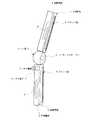
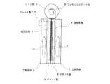
図1は本発明の実施形態による折畳み式携帯無線機の折畳んだ状態の概略図である。図2Aは図1の点線Aで切断した断面であり、展開した状態の模式図、図2Bは図1の点線Aで切断した断面の模式図である。 FIG. 1 is a schematic view of a folding portable wireless device according to an embodiment of the present invention in a folded state. 2A is a cross-sectional view taken along the dotted line A in FIG. 1, and is a schematic view of the developed state. FIG. 2B is a schematic cross-sectional view taken along the dotted line A in FIG.
本実施形態の折畳み式携帯無線機は、図1に示すように、第一の筐体としての上部筐体1と、第二の筐体としての下部筐体2と、上部筐体1と下部筐体2とを相互に回転自在に連結しているヒンジ部3とを備えている。本形態では上部筐体1と下部筐体2はいずれも、非導電材料で構成されている。例えば、上部筐体1及び下部筐体2の双方を、モールドで形成された非導電性物質からなるものとする。 As shown in FIG. 1, the foldable portable wireless device according to the present embodiment includes an
上部筐体1の内部には、第一の基板としての回路基板4が収納されている。下部筐体2の内部には、第二の基板としての回路基板5が収納されている。回路基板4と回路基板5とは、ヒンジ部3の内部を通ったフレキシブルケーブル6により電気的に接続されている。なお、上部筐体1と下部筐体2とは展開状態において相互間に電流(特に高周波電流)が流れないように相互に絶縁された状態にあり、回路基板4と回路基板5とはフレキシブルケーブル6のみを介して相互に接続されている。 A circuit board 4 as a first board is accommodated in the
回路基板5のヒンジ部3寄りに、アンテナ素子7が接続されている。なお、アンテナ素子7は、図2Aとは異なり、回路基板4のヒンジ部3寄りに配置されていても良い。 An
アンテナ素子7として用いられる形状としては、例えば、板金で構成された逆Fアンテナまたは逆Lアンテナ、あるいは、ワイヤより構成されたヘリカルアンテナなど、種々の形状が考えられる。 As the shape used as the
フレキシブルケーブル6は、ヒンジ部3の周囲に少なくとも一回巻かれた状態で配置されている。フレキシブルケーブル6の巻き数を2以上とする場合は、フレキシブルケーブル6はヒンジ部3の長さ方向の軸線を中心としてヒンジ部3の長さ方向にスパイラル状に配置する。このフレキシブルケーブル6を平面状に伸ばしたときの長さは、上部筐体1内の回路基板4を流れる電流の位相と下部筐体2内の回路基板5を流れる電流の位相とが同相(電流の流れる向きが同じ)になるように設定されている。 The
また、上部筐体1および下部筐体2のそれぞれに、金属などの導電性材料でつくられたグランド板8,9が配設されている。グランド板8,9は、上部筐体1と下部筐体2の、折畳み時に接触する2つの面にそれぞれ沿って配置される。グランド板8と回路基板4、グランド板9と回路基板5は、それぞれ電気的に接続されている。そして、グランド板8とグランド板9は、上部筐体1と下部筐体2を折畳んだ時に接触するようになっている。図2A及び図2Bでは、上部筐体1における下部筐体2との接触面にグランド板8を配置し、下部筐体2における上部筐体1との接触面にグランド板9を配置している。しかし、図のようにグランド板を配置することが設計において困難である場合は、グランド板8とグランド板9はそれぞれ上部筐体1と下部筐体2の内部に配置される。そして、各々のグランド板8,9の一部が各筐体1,2の内部から表面に電気的に導出され、上部筐体1と下部筐体2を折畳んだ時に接触するように配置される。 In addition,
なお、本実施形態の携帯無線機が携帯電話である場合は、上部筐体1には、レシーバ、ディスプレイなどが備えられている。下部筐体2には、マイク、バッテリ、および、複数のデータ入力用ボタンまたはキーを含むキー操作部などが備えられている。 When the portable wireless device of the present embodiment is a mobile phone, the
本実施形態の折畳み式携帯無線機によれば、図2Aに示すように開いた状態(展開状態)では各々の筐体1,2の回路基板4,5を流れる電流が同相になっている。すなわち、回路基板4に流れる電流は矢印P方向(ヒンジ部3から離れる方向)に、回路基板5に流れる電流は矢印Q方向(ヒンジ部3に向かう方向)にそれぞれ流れる。これは、フレキシブルケーブル6が、上部筐体1内の回路基板4を流れる電流と下部筐体2内の回路基板5を流れる電流の位相が同相になるような長さに設定されているためである。 According to the foldable portable wireless device of the present embodiment, the currents flowing through the
そして、図2Bに示すように閉じた時(折畳んだ時)には、グランド板8とグランド板9が接触する。これにより、回路基板4と回路基板5とグランド板8とグランド板9を電気的に一枚の金属板のようにみせることができる。この結果、各々の筐体1,2の回路基板4,5を流れる電流が同相になる。すなわち、回路基板4に流れる電流は矢印S方向(ヒンジ部3に向かう方向)に、回路基板5に流れる電流は矢印Q方向(ヒンジ部3に向かう方向)にそれぞれ流れる。 Then, when closed (folded) as shown in FIG. 2B, the
このように展開状態から折畳み状態にしても、上部筐体1及び下部筐体2の内部を流れる2つの電流が相互に打ち消し合うことはないので、アンテナの放射効率が低下しない。つまり、展開時および折畳み時ともに良好なアンテナ特性を維持できる。 Even in the folded state from the expanded state in this way, the two currents flowing inside the
次に、他の実施形態について述べる。 Next, another embodiment will be described.
上述した実施形態は、図2Bに示したように2枚のグランド板8,9が上部筐体1と下部筐体2を折畳んだ時に接触する構造である。 In the embodiment described above, the two
2枚のグランド板8,9は同じ大きさである必要はなく、接触点を有すればグランド板8,9の位置関係および形状は自由である。グランド板8,9の設計例を図3に示す。 The two
図3(a)に示すように2枚のグランド板8,9が同じ大きさで、折畳み時に両者の位置が合うようにしたり、図3(b)のように互いの位置がずれたりしても良い。また、図3(c)(d)に示すように各々のグランド板8,9の大きさが異なっていても良い。さらに、図3(e)に示すようにグランド板8,9に穴が開いていても良い。この穴はLCDユニットのための窓として使用できる。さらに、図示しないが、キー操作を行なえるようにグランド板にドーム形状を有していても良い。勿論、グランド板8,9は四角形である必要はなく、任意の形状をとることができる。 As shown in FIG. 3 (a), the two
また、上述した実施形態では、上部筐体1と下部筐体2を折畳んだ時にグランド板8,9が接触する構造をとっているが、折畳み時に2枚のグランド板8,9を接触させず、容量結合させることでも本発明の効果を得ることができる。 In the above-described embodiment, the
この場合、容量結合を十分得るためにグランド板8,9は回路基板4,5と同程度の大きさであることが望ましく、折畳み時の2枚のグランド板の距離は近いほど効果を得られる。 In this case, it is desirable that the
また、上述した実施形態において、上部筐体1と下部筐体2に用いられる材料はどちらか一方は導電性材料でも可能である。この場合、導電性材料で構成された筐体内のグランド板は不要となる。つまり、導電性材料を含んで構成された筐体に、この筐体内に収納されている回路基板のグランドを接続しておき、導電性材料の筐体と非導電材料の筐体とを折畳むと、非導電材料の筐体内のグランド板と導電性材料の筐体とが接触または近接する構造であってもよい。 In the above-described embodiment, one of the materials used for the
また、上述した実施形態において、グランド板8,9の代わりに、非導電材料で構成された上部筐体1及び/又は下部筐体2の表面に、蒸着やメッキや塗装などにより、導電性物質からなる膜が形成されたものでもよい。この場合は、表面に導電性の膜が形成された非導電材料の筐体内にはグランド板は不要となる。 Further, in the above-described embodiment, instead of the
また、上述した実施形態において、グランド板8及び9は金属などの導電性部材に限られず、非導電材料に導電性塗料を塗ることでも代用できる。 In the above-described embodiment, the
1 上部筐体
2 下部筐体
3 ヒンジ部
4,5 回路基板
6 フレキシブルケーブル
7 アンテナ素子
8、9 グランド板(地板)DESCRIPTION OF
Claims (6)
Translated fromJapanese第二の回路基板を収納する第二の筐体と、
前記第一の筐体と前記第二の筐体とを回動自在に連結するヒンジ部と、
前記第一の回路基板と前記第二の回路基板とを前記ヒンジ部を介して電気的に接続するフレキシブルケーブルと、
前記第一の回路基板及び前記第二の回路基板の何れか一方に接続され、かつ、前記ヒンジ部の近傍に配置されたアンテナ素子と、を備え、
前記フレキシブルケーブルの長さが、前記第一の筐体の前記第一の回路基板を流れる電流と前記第二の筐体の前記第二の回路基板を流れる電流の位相が同相になるように調整されている折畳み式携帯無線機において、
前記第一の筐体および前記第二の筐体の両方が非導電性材料で構成されており、前記第一の回路基板および前記第二の回路基板のそれぞれにグランド板が電気的に接続され、前記第一の回路基板に電気接続されたグランド板と前記第二の回路基板に電気接続されたグランド板とが、前記第一の筐体と前記第二の筐体とを折畳んだ時に接触もしくは近接する構造となっていることを特徴とする折畳み式携帯無線機。A first housing for housing a first circuit board;
A second housing for housing the second circuit board;
A hinge portion that rotatably connects the first housing and the second housing;
A flexible cable for electrically connecting the first circuit board and the second circuit board via the hinge portion;
An antenna element connected to any one of the first circuit board and the second circuit board and disposed in the vicinity of the hinge portion,
The length of the flexible cable is adjusted so that the phase of the current flowing through the first circuit board in the first casing and the current flowing through the second circuit board in the second casing are in phase. In the foldable portable radio that is
Both the first casing and the second casing are made of a non-conductive material, and a ground plate is electrically connected to each of the first circuit board and the second circuit board. When the ground plate electrically connected to the first circuit board and the ground plate electrically connected to the second circuit board are folded between the first casing and the second casing. A foldable portable wireless device characterized in that it has a structure of contact or proximity.
第二の回路基板を収納する第二の筐体と、
前記第一の筐体と前記第二の筐体とを回動自在に連結するヒンジ部と、
前記第一の回路基板と前記第二の回路基板とを前記ヒンジ部を介して電気的に接続するフレキシブルケーブルと、
前記第一の回路基板及び前記第二の回路基板の何れか一方に接続され、かつ、前記ヒンジ部の近傍に配置されたアンテナ素子と、を備え、
前記フレキシブルケーブルの長さが、前記第一の筐体の前記第一の回路基板を流れる電流と前記第二の筐体の前記第二の回路基板を流れる電流の位相が同相になるように調整されている折畳み式携帯無線機において、
前記第一の筐体および前記第二の筐体のいずれか一方が非導電性材料で構成され他方が導電性材料を含んで構成されており、
前記非導電性材料で構成された側の筐体に収納された回路基板にグランド板が電気的に接続され、前記導電性材料を含んで構成された側の筐体に当該筐体に収納された回路基板が接地されており、
前記グランド板と、前記導電性材料を含んで構成された側の筐体とが、前記第一の筐体と前記第二の筐体とを折畳んだ時に接触もしくは近接する構造となっていることを特徴とする折畳み式携帯無線機。A first housing for housing a first circuit board;
A second housing for housing the second circuit board;
A hinge portion that rotatably connects the first housing and the second housing;
A flexible cable for electrically connecting the first circuit board and the second circuit board via the hinge portion;
An antenna element connected to any one of the first circuit board and the second circuit board and disposed in the vicinity of the hinge portion,
The length of the flexible cable is adjusted so that the phase of the current flowing through the first circuit board in the first casing and the current flowing through the second circuit board in the second casing are in phase. In the foldable portable radio that is
Either one of the first casing and the second casing is made of a non-conductive material and the other is made of a conductive material,
A ground plate is electrically connected to the circuit board housed in the housing made of the non-conductive material, and is housed in the housing in the housing made up of the conductive material. The circuit board is grounded,
The ground plate and the housing on the side configured to include the conductive material are in contact with or close to each other when the first housing and the second housing are folded. A foldable portable radio characterized by that.
Priority Applications (1)
| Application Number | Priority Date | Filing Date | Title |
|---|---|---|---|
| JP2005328701AJP4692750B2 (en) | 2005-11-14 | 2005-11-14 | Folding portable radio |
Applications Claiming Priority (1)
| Application Number | Priority Date | Filing Date | Title |
|---|---|---|---|
| JP2005328701AJP4692750B2 (en) | 2005-11-14 | 2005-11-14 | Folding portable radio |
Publications (2)
| Publication Number | Publication Date |
|---|---|
| JP2007135148Atrue JP2007135148A (en) | 2007-05-31 |
| JP4692750B2 JP4692750B2 (en) | 2011-06-01 |
Family
ID=38156419
Family Applications (1)
| Application Number | Title | Priority Date | Filing Date |
|---|---|---|---|
| JP2005328701AExpired - Fee RelatedJP4692750B2 (en) | 2005-11-14 | 2005-11-14 | Folding portable radio |
Country Status (1)
| Country | Link |
|---|---|
| JP (1) | JP4692750B2 (en) |
Cited By (4)
| Publication number | Priority date | Publication date | Assignee | Title |
|---|---|---|---|---|
| WO2010079546A1 (en)* | 2009-01-06 | 2010-07-15 | パナソニック株式会社 | Mobile radio device |
| JP2010258588A (en)* | 2009-04-22 | 2010-11-11 | Panasonic Corp | Portable radio |
| WO2011121956A1 (en)* | 2010-03-31 | 2011-10-06 | 日本電気株式会社 | Wireless communication device and current-reducing method |
| CN115425390A (en)* | 2022-09-05 | 2022-12-02 | 荣耀终端有限公司 | Terminal antenna and electronic equipment |
Citations (3)
| Publication number | Priority date | Publication date | Assignee | Title |
|---|---|---|---|---|
| JP2003008320A (en)* | 2001-06-25 | 2003-01-10 | Nec Saitama Ltd | Portable radio apparatus |
| JP2003273767A (en)* | 2002-03-18 | 2003-09-26 | Murata Mfg Co Ltd | Radio communication apparatus |
| JP2004172919A (en)* | 2002-11-20 | 2004-06-17 | Nec Saitama Ltd | Portable terminal |
- 2005
- 2005-11-14JPJP2005328701Apatent/JP4692750B2/ennot_activeExpired - Fee Related
Patent Citations (3)
| Publication number | Priority date | Publication date | Assignee | Title |
|---|---|---|---|---|
| JP2003008320A (en)* | 2001-06-25 | 2003-01-10 | Nec Saitama Ltd | Portable radio apparatus |
| JP2003273767A (en)* | 2002-03-18 | 2003-09-26 | Murata Mfg Co Ltd | Radio communication apparatus |
| JP2004172919A (en)* | 2002-11-20 | 2004-06-17 | Nec Saitama Ltd | Portable terminal |
Cited By (9)
| Publication number | Priority date | Publication date | Assignee | Title |
|---|---|---|---|---|
| WO2010079546A1 (en)* | 2009-01-06 | 2010-07-15 | パナソニック株式会社 | Mobile radio device |
| JP2010258588A (en)* | 2009-04-22 | 2010-11-11 | Panasonic Corp | Portable radio |
| WO2011121956A1 (en)* | 2010-03-31 | 2011-10-06 | 日本電気株式会社 | Wireless communication device and current-reducing method |
| CN102834969A (en)* | 2010-03-31 | 2012-12-19 | 日本电气株式会社 | Radio communication apparatus and current reducing method |
| CN102834969B (en)* | 2010-03-31 | 2015-02-11 | 联想创新有限公司(香港) | Wireless communication device and current reduction method |
| US9065891B2 (en) | 2010-03-31 | 2015-06-23 | Lenovo Innovations Limited | Radio communication apparatus and current reducing method |
| JP5805626B2 (en)* | 2010-03-31 | 2015-11-04 | レノボ・イノベーションズ・リミテッド(香港) | Wireless communication apparatus and current reduction method |
| EP2555323A4 (en)* | 2010-03-31 | 2016-11-30 | Nec Corp | Wireless communication device and current-reducing method |
| CN115425390A (en)* | 2022-09-05 | 2022-12-02 | 荣耀终端有限公司 | Terminal antenna and electronic equipment |
Also Published As
| Publication number | Publication date |
|---|---|
| JP4692750B2 (en) | 2011-06-01 |
Similar Documents
| Publication | Publication Date | Title |
|---|---|---|
| JP4331072B2 (en) | Portable radio | |
| WO2006046712A1 (en) | Foldable portable radio | |
| JP5121649B2 (en) | Wireless device | |
| JP2005303542A (en) | Wireless communication device | |
| JP4401889B2 (en) | Foldable portable radio | |
| JP4689229B2 (en) | Wireless communication terminal | |
| JPWO2009034648A1 (en) | Wireless communication device | |
| CN101821901B (en) | Wireless device sliding in short-side direction | |
| JPWO2006057350A1 (en) | Folding portable wireless device | |
| JP2009141623A (en) | Wireless device and antenna device | |
| JP5583030B2 (en) | Wireless terminal device | |
| JP4692750B2 (en) | Folding portable radio | |
| JP2008227560A (en) | Portable wireless apparatus | |
| JP2005136668A (en) | Folding portable wireless device. | |
| JP2006005567A (en) | Portable radio | |
| JP2011217184A (en) | Mobile wireless apparatus | |
| JP2005192055A (en) | Openable wireless communication device | |
| JP4962281B2 (en) | ANTENNA DEVICE AND PORTABLE TERMINAL USING THE SAME | |
| JP2008153801A (en) | Terminal device having antenna and wireless function | |
| JP2005333202A (en) | Foldable portable radio | |
| JP4642588B2 (en) | Portable wireless device | |
| JP2008270921A (en) | Radio communication device | |
| JP4696887B2 (en) | Mobile device | |
| JP5757559B2 (en) | Portable radio | |
| JP2011120072A (en) | Portable radio |
Legal Events
| Date | Code | Title | Description |
|---|---|---|---|
| A621 | Written request for application examination | Free format text:JAPANESE INTERMEDIATE CODE: A621 Effective date:20081016 | |
| A977 | Report on retrieval | Free format text:JAPANESE INTERMEDIATE CODE: A971007 Effective date:20100913 | |
| A131 | Notification of reasons for refusal | Free format text:JAPANESE INTERMEDIATE CODE: A131 Effective date:20101124 | |
| A521 | Written amendment | Free format text:JAPANESE INTERMEDIATE CODE: A523 Effective date:20110106 | |
| TRDD | Decision of grant or rejection written | ||
| A01 | Written decision to grant a patent or to grant a registration (utility model) | Free format text:JAPANESE INTERMEDIATE CODE: A01 Effective date:20110126 | |
| A01 | Written decision to grant a patent or to grant a registration (utility model) | Free format text:JAPANESE INTERMEDIATE CODE: A01 | |
| A61 | First payment of annual fees (during grant procedure) | Free format text:JAPANESE INTERMEDIATE CODE: A61 Effective date:20110208 | |
| FPAY | Renewal fee payment (event date is renewal date of database) | Free format text:PAYMENT UNTIL: 20140304 Year of fee payment:3 | |
| R150 | Certificate of patent or registration of utility model | Free format text:JAPANESE INTERMEDIATE CODE: R150 | |
| S111 | Request for change of ownership or part of ownership | Free format text:JAPANESE INTERMEDIATE CODE: R313113 | |
| R350 | Written notification of registration of transfer | Free format text:JAPANESE INTERMEDIATE CODE: R350 | |
| R250 | Receipt of annual fees | Free format text:JAPANESE INTERMEDIATE CODE: R250 | |
| LAPS | Cancellation because of no payment of annual fees |