JP2007133482A - Computer for automatically displaying parent object and display method thereof - Google Patents
Computer for automatically displaying parent object and display method thereofDownload PDFInfo
- Publication number
- JP2007133482A JP2007133482AJP2005323585AJP2005323585AJP2007133482AJP 2007133482 AJP2007133482 AJP 2007133482AJP 2005323585 AJP2005323585 AJP 2005323585AJP 2005323585 AJP2005323585 AJP 2005323585AJP 2007133482 AJP2007133482 AJP 2007133482A
- Authority
- JP
- Japan
- Prior art keywords
- display
- displayed
- display area
- objects
- output device
- Prior art date
- Legal status (The legal status is an assumption and is not a legal conclusion. Google has not performed a legal analysis and makes no representation as to the accuracy of the status listed.)
- Pending
Links
Images


Classifications
- G—PHYSICS
- G06—COMPUTING OR CALCULATING; COUNTING
- G06F—ELECTRIC DIGITAL DATA PROCESSING
- G06F9/00—Arrangements for program control, e.g. control units
- G06F9/06—Arrangements for program control, e.g. control units using stored programs, i.e. using an internal store of processing equipment to receive or retain programs
- G06F9/44—Arrangements for executing specific programs
- G06F9/448—Execution paradigms, e.g. implementations of programming paradigms
- G06F9/4488—Object-oriented
- G06F9/4492—Inheritance
Landscapes
- Engineering & Computer Science (AREA)
- Software Systems (AREA)
- Theoretical Computer Science (AREA)
- Physics & Mathematics (AREA)
- General Engineering & Computer Science (AREA)
- General Physics & Mathematics (AREA)
- User Interface Of Digital Computer (AREA)
- Information Retrieval, Db Structures And Fs Structures Therefor (AREA)
Abstract
Translated fromJapaneseDescription
Translated fromJapanese本願明細書で開示される技術は、階層化された複数のオブジェクトを含む計算機システムに関し、特に、階層化されたオブジェクトの表示方法に関する。 The technology disclosed in this specification relates to a computer system including a plurality of hierarchized objects, and more particularly, to a display method for hierarchized objects.
階層化された複数のオブジェクト(構成要素)を含む計算機システムにおいて、それらのオブジェクトを画面上に表示するグラフィカルユーザインターフェース(GUI)が開示されている(例えば、特許文献1参照)。特許文献1によれば、情報処理装置と、その情報処理装置が管理する論理ユニット(LU)がツリー状の図形として表示される。このため、特許文献1によれば、オブジェクトの階層構造が視覚的にわかりやすく表示される。システム管理者は、上記のGUIを使用して、階層における上位のオブジェクト(親オブジェクト)に関連付けられた下位のオブジェクト(子オブジェクト)を容易に特定することができる。
計算機システムにおいては、一つの子オブジェクトが複数の親オブジェクトに関連する場合がある。例えば、ホスト計算機がストレージシステム内の論理デバイスにアクセスする場合、各論理デバイスは、その論理デバイスを格納するストレージシステムと関連付けられると同時に、その論理デバイスにアクセスするホスト計算機とも関連付けられる。この場合、ホスト計算機及びストレージシステムは、共に、論理デバイスの親オブジェクトである。 In a computer system, one child object may be related to a plurality of parent objects. For example, when a host computer accesses a logical device in the storage system, each logical device is associated with a storage system that stores the logical device and at the same time with a host computer that accesses the logical device. In this case, both the host computer and the storage system are parent objects of the logical device.
例えば、システム管理者は、あるホスト計算機がアクセスする論理デバイスがどのストレージシステムに属しているかを知るために、各ストレージシステムの子オブジェクトを参照して、それらの子オブジェクトに目的の論理デバイスが含まれるか否かを調査する必要がある。調査の範囲に含まれるオブジェクトの数が多いほど、あるいは、オブジェクトの階層が深いほど、この調査のための作業量は増大する。 For example, in order to know to which storage system a logical device accessed by a host computer belongs, the system administrator refers to the child object of each storage system and includes the target logical device in those child objects. It is necessary to investigate whether or not The greater the number of objects included in the survey area, or the deeper the object hierarchy, the greater the amount of work for this survey.
このように、従来の技術によれば、親オブジェクトに関連付けられた子オブジェクトを特定することは容易であったが、一つの子オブジェクトが複数の親オブジェクトに関連付けられている場合に、子オブジェクトに関連付けられた全ての親オブジェクトを特定することは容易でなかった。 As described above, according to the conventional technique, it is easy to specify a child object associated with a parent object. However, when one child object is associated with a plurality of parent objects, It was not easy to identify all the associated parent objects.
本願で開示する代表的な発明は、ホスト計算機及び記憶サブシステムを備える計算機システムを管理する方法であって、前記管理計算機は、第1ネットワークを介して前記ホスト計算機及び前記記憶サブシステムと接続され、前記ホスト計算機及び前記記憶サブシステムは、第2ネットワークを介して相互に接続され、前記管理計算機は、前記第1ネットワークを介して通信する第1インターフェースと、前記第1インターフェースに接続される第1プロセッサと、前記第1プロセッサに接続される第1メモリと、入力を受ける入力装置と、情報を表示する出力装置と、を備え、前記ホスト計算機は、前記第1ネットワークに接続される第2インターフェースと、前記第2ネットワークに接続される第3インターフェースと、前記第2インターフェース及び前記第3インターフェースに接続される第2プロセッサと、前記第2プロセッサに接続される第2メモリと、を備え、前記記憶サブシステムは、前記ホスト計算機が使用するデータを格納するディスクドライブと、前記ディスクドライブを制御するコントローラと、を備え、前記方法は、前記計算機システムに含まれ、相互に関連付けられた対象物を前記出力装置の表示領域に表示し、前記入力装置が前記対象物を指示する入力を受けると、当該指示された対象物の上位に関連付けられた前記対象物を他の前記対象物と異なる態様によって前記出力装置の表示領域に表示することを特徴とする。 A representative invention disclosed in the present application is a method for managing a computer system including a host computer and a storage subsystem, and the management computer is connected to the host computer and the storage subsystem via a first network. The host computer and the storage subsystem are connected to each other via a second network, and the management computer is connected to the first interface that communicates via the first network and the first interface. One host, a first memory connected to the first processor, an input device for receiving input, and an output device for displaying information, wherein the host computer is connected to the first network. An interface, a third interface connected to the second network, and the second interface And a second processor connected to the third interface and a second memory connected to the second processor, and the storage subsystem includes a disk drive for storing data used by the host computer And a controller for controlling the disk drive, the method being included in the computer system and displaying objects associated with each other in a display area of the output device, wherein the input device displays the object. When receiving an instruction to instruct, the object associated with a higher rank of the instructed object is displayed in a display area of the output device in a manner different from that of the other object.
本発明の一形態によれば、子オブジェクトに関連付けられた親オブジェクトを容易に特定することができる。 According to an aspect of the present invention, a parent object associated with a child object can be easily specified.
以下、本発明の実施の形態を、図面を参照して説明する。 Hereinafter, embodiments of the present invention will be described with reference to the drawings.
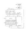
図1は、本発明の実施の形態の計算機システムの構成を示すブロック図である。 FIG. 1 is a block diagram showing a configuration of a computer system according to the embodiment of this invention.
本実施の形態の計算機システムは、管理者用PC100、管理サーバ110、一つ以上のホスト120及び一つ以上のサブシステム140を備える。 The computer system of this embodiment includes an administrator PC 100, a
各ホスト120及び各サブシステム140は、いわゆるストレージエリアネットワーク(SAN)130によって相互に接続される。一方、管理サーバ110は、各ホスト120及び各サブシステム140とインターネットプロトコル(IP)ネットワーク150によって接続される。なお、SAN130及びIPネットワーク150の代わりに他の種類のネットワークが使用されてもよい。 Each
管理者用PC100は、システム管理者が本実施の形態の計算機システムを管理するために使用する計算機である。管理者用PC100は、管理サーバ110に接続されたいわゆるパーソナルコンピュータ(PC)であってもよい。後で詳細に説明するように、管理者用PC100において、本発明の親オブジェクト表示方法が実行される(図16等参照)。管理者用PC100の構成については、後で詳細に説明する(図2参照)。 The administrator PC 100 is a computer that is used by a system administrator to manage the computer system according to the present embodiment. The administrator PC 100 may be a so-called personal computer (PC) connected to the
管理サーバ110は、本実施の形態の計算機システムを管理する計算機である。管理サーバ110は、IPネットワーク150を経由してホスト120及びサブシステム140と通信し、種々の情報を取得する(図7等参照)。管理サーバ110の構成については、後で詳細に説明する(図3参照)。 The
ホスト120は、サブシステム140を使用する計算機である。ユーザは、ホスト120を使用して種々の業務を実行する。ホスト120は、必要に応じて、サブシステム140にデータを書き込み、又は、サブシステム140からデータを読み出す。ホスト120の構成については、後で詳細に説明する(図4参照)。 The
サブシステム140は、ホスト120によって書き込まれたデータを格納するストレージシステム(記憶サブシステム)である。サブシステム140は、コントローラ141及び複数のディスクドライブ142を備える。 The
コントローラ141は、SAN130を介して、ホスト120からデータの書き込み要求及び読み出し要求を受信すると共に、これらの要求の対象のデータを送受信する。さらに、コントローラ141は、ディスクドライブ142を制御して、要求の対象のデータをディスクドライブ142に書き込み、又は、ディスクドライブ142から読み出す。コントローラ141の構成については、後で詳細に説明する(図5参照)。 The
各ディスクドライブ142は、例えば、ハードディスクドライブ(HDD)である。ディスクドライブ142には、ホスト120から書き込まれたデータが格納される。 Each disk drive 142 is, for example, a hard disk drive (HDD). The disk drive 142 stores data written from the
複数のディスクドライブ142は、いわゆるRAID(Redundant Arrays of Inexpensive Disks)を構成する。所定の数(例えば、4個)のディスクドライブ142が一つのパリティグループ143を構成する。パリティグループ143は、RAIDを構成する単位である。一つのパリティグループ内の一つのディスクドライブ142のデータが障害等によって消失した場合、そのパリティグループ143の残りのディスクドライブ142のデータに基づいて、消失したデータが復元される。サブシステム140は、任意の数のパリティグループ143を備えることができる。 The plurality of disk drives 142 constitute so-called RAID (Redundant Arrays of Inexpensive Disks). A predetermined number (for example, four) of disk drives 142 constitutes one
ここで、オブジェクトについて説明する。オブジェクトとは、計算機システムにおいて種々の処理の対象物となる物理的な又は論理的な構成要素である。例えば、図1において、各ホスト120、各サブシステム140及び各パリティグループ143は、オブジェクトである。さらに、後述する各論理デバイス(LDEV)及び各論理ユニット(LU)もオブジェクトである(図6参照)。 Here, the object will be described. An object is a physical or logical component that is an object of various processes in a computer system. For example, in FIG. 1, each
各オブジェクトは、他のオブジェクトと関連付けられる。 Each object is associated with other objects.
例えば、あるサブシステム140が備えるあるパリティグループ143がある論理デバイスを含む場合、そのサブシステム140の下位にそのパリティグループ143が関連付けられ、そのパリティグループ143の下位にその論理デバイスが関連付けられる。あるオブジェクトの上位に直接関連付けられるオブジェクトを親オブジェクト、下位に直接関連付けられるオブジェクトを子オブジェクトと記載する。 For example, when a
なお、以下の説明において、上位に関連付けられるオブジェクト(又は、関連する上位オブジェクト)とは、親オブジェクトに加えて、その親オブジェクトの上位に関連付けられるオブジェクトも含む。 In the following description, an object associated with a higher level (or a related higher level object) includes an object associated with a higher level of the parent object in addition to the parent object.
次に、本実施の形態の計算機システムの各部位について説明する。 Next, each part of the computer system of this embodiment will be described.
図2は、本発明の実施の形態の管理者用PC100の構成を示すブロック図である。 FIG. 2 is a block diagram illustrating a configuration of the
本実施の形態の管理者用PC100は、相互に接続された入力装置201、出力装置202、CPU203、描画プロセッサ204、インターフェース(I/F)205及びメモリ206を備える。 The administrator PC 100 according to the present embodiment includes an
入力装置201は、システム管理者が管理者用PC100に指示又はデータを入力するために使用される。本実施の形態はグラフィカルユーザインターフェース(GUI)を提供するため、入力装置201は、少なくとも、出力装置202に表示されたオブジェクトを指示するためのポインティングデバイス(例えば、マウス)を含む。 The
出力装置202は、管理者用PC100がシステム管理者に情報を表示するために使用される。本実施の形態は計算機システムのオブジェクトをGUIによって視覚的に表示するため、出力装置202は、少なくとも、表示画面(例えば、CRT又は液晶画面)を含む。 The output device 202 is used by the administrator PC 100 to display information to the system administrator. Since the present embodiment visually displays an object of a computer system using a GUI, the output device 202 includes at least a display screen (for example, a CRT or a liquid crystal screen).
CPU203は、メモリ206に格納されたプログラムを実行するプロセッサである。 The
描画プロセッサ204は、出力装置202に画面を表示する処理を実行するプロセッサである。具体的には、描画プロセッサ204は、メモリ206に格納された描画プログラム208を実行して、表示メモリ211に格納された情報に従って、出力装置202に画面を表示する。なお、描画プロセッサ204は、画面を表示する処理を高速に実行するために設けられるものである。このため、高速な処理が要求されない場合、管理者用PC100は描画プロセッサ204を備えなくてもよい。この場合、CPU203が描画プログラム208を実行する。 The
I/F205は、管理サーバ110を介してIPネットワークと接続され、管理者用PC100が管理サーバ110と通信するために使用される。管理者用PC100は、I/F205を介して管理サーバ110と通信することによって、管理サーバ110がホスト計算機120及びサブシステム140から収集した情報を参照することができる。 The I /
メモリ206は、CPU203又は描画プロセッサ204によって実行されるプログラムを格納する記憶装置である。メモリ206は、さらに、プログラムが実行される際に参照される情報を格納する。メモリ206は、例えば、半導体メモリ、磁気ディスクドライブ又はこれらの組み合わせであってもよい。 The
本実施の形態のメモリ206は、オブジェクト表示プログラム207、描画プログラム208、オブジェクト管理テーブル209、表示制御テーブル210及び表示メモリ211を格納する。これらのプログラム等については、後で詳細に説明する。 The
図3は、本発明の実施の形態の管理サーバ110の構成を示すブロック図である。 FIG. 3 is a block diagram illustrating a configuration of the
本実施の形態の管理サーバ110は、相互に接続されたCPU301、I/F302、I/F303及びメモリ304を備える。 The
CPU301は、メモリ304に格納されたプログラムを実行するプロセッサである。 The
I/F302は、管理者用PC100と接続され、管理サーバ110が管理者用PC100と通信するために使用される。 The I /
I/F303は、IPネットワーク150を介して各ホスト120及び各サブシステム140と接続され、これらのホスト120等と通信するために使用される。I/F303は、例えば、一般的なネットワークインターフェースカード(NIC)であってもよい。 The I /
メモリ304は、CPU301によって実行されるプログラム等を格納する記憶装置である。メモリ304は、例えば、半導体メモリ、磁気ディスクドライブ又はこれらの組み合わせであってもよい。 The
本実施の形態のメモリ304は、収集プログラム305及びデータベース306を格納する。収集プログラム305は、各ホスト120及び各サブシステム140からオブジェクトに関する情報を収集して、データベース306に格納する。収集プログラム305が収集する情報については、後で詳細に説明する(図7等参照)。 The
なお、本実施の形態では、管理者用PC100と管理サーバ110が別のハードウエアによって実現されるが、一つのハードウエアが管理者用PC100及び管理サーバ110を兼ねてもよい。例えば、メモリ206に収集プログラム305及びデータベース306が格納された管理者用PC100のI/F205を直接IPネットワーク150に接続してもよい。 In this embodiment, the
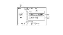
図4は、本発明の実施の形態のホスト120の構成を示すブロック図である。 FIG. 4 is a block diagram illustrating a configuration of the
本実施の形態のホスト120は、相互に接続されたCPU401、I/F402、I/F403及びメモリ404を備える。 The
CPU401は、メモリ404に格納されたプログラムを実行するプロセッサである。 The CPU 401 is a processor that executes a program stored in the
I/F402は、IPネットワーク150を介して管理サーバ110と接続され、管理サーバ110と通信するために使用される。I/F402は、例えば、一般的なネットワークインターフェースカード(NIC)であってもよい。 The I /
I/F403は、SAN130に接続され、SAN130を介してサブシステム140と通信する。SAN130においてファイバーチャネル(FC)プロトコルが使用される場合、I/F403は、例えば、いわゆるホストバスアダプタ(HBA)である。ホスト120は、複数のI/F403を備えてもよい。 The I /
メモリ404は、CPU401によって実行されるプログラム等を格納する記憶装置である。メモリ404は、例えば、半導体メモリ、磁気ディスクドライブ又はこれらの組み合わせであってもよい。 The
本実施の形態のメモリ404は、アプリケーションプログラム405及びLU割り当て情報406を格納する。アプリケーションプログラム405は、ホスト120のユーザが種々の業務を実行するために使用される。メモリ404は、複数のアプリケーションプログラム405を備えてもよい。アプリケーションプログラム405は、必要に応じて、サブシステム140内の論理ユニット(LU)(後述)に対するアクセス要求を発行する。LU割り当て情報406は、各ホスト120と各LUとの関連付けについての情報を含む。LU割り当て情報406については、後で詳細に説明する(図7等参照)。 The
図5は、本発明の実施の形態のコントローラ141の構成を示すブロック図である。 FIG. 5 is a block diagram illustrating a configuration of the
本実施の形態のホスト120は、相互に接続されたCPU501、I/F502及びメモリ503を備える。 The
CPU501は、メモリ503に格納されたプログラム(図示省略)を実行するプロセッサである。 The
I/F502は、SAN130に接続され、SAN130を介してホスト120と通信する。コントローラ141は、複数のI/F502を備えてもよい。 The I /
メモリ503は、CPU501によって実行されるプログラム(図示省略)及びその他の情報を格納する記憶装置である。メモリ503は、例えば、半導体メモリであってもよい。 The
本実施の形態のメモリ503は、LDEV割り当て情報504を格納する。LDEV割り当て情報504は、各LDEVと各LUとの関連付けについての情報を含む。 The
LU割り当て情報406及びLDEV割り当て情報504によって、ホスト120とLDEVとが関連付けられる。 The
図6は、本発明の実施の形態の計算機システムの論理的な構成を示すブロック図である。 FIG. 6 is a block diagram showing a logical configuration of the computer system according to the embodiment of this invention.
図6は、図1に示す本実施の形態の計算機システムの論理的な構成を示す。図6は、説明のため、二つのホスト120及び二つのサブシステム140のみを示す。他の部分及び詳細な構成については、図示を省略する。 FIG. 6 shows a logical configuration of the computer system of this embodiment shown in FIG. FIG. 6 shows only two
図6において、各ホスト120は、ホスト名によって識別される。図6に示す一方のホスト120のホスト名は「Host1」、もう一方のホスト名は「Host2」である。以下の説明において、ホスト名が「Host1」であるホスト120を単にHost1と記載する。Host2についても同様である。 In FIG. 6, each
各サブシステム140は、サブシステム名によって識別される。図6に示す一方のサブシステム140のサブシステム名は「Sub1」、もう一方のサブシステム名は「Sub2」である。以下の説明において、サブシステム名が「Sub1」であるサブシステム140を単にSub1と記載する。Sub2についても同様である。 Each
各ホスト120のI/F403及び各サブシステム140のI/F502は、World Wide Name(WWN)によって識別される。WWNは、各I/F403及びI/F502を全世界で一意に識別する識別子である。図6の例において、Host1が備える二つのI/F403のWWNは、それぞれ、「WWN1」及び「WWN2」である。Host2が備える二つのI/F403のWWNは、それぞれ、「WWN3」及び「WWN4」である。Sub1のコントローラ141が備える四つのI/F502のWWNは、それぞれ、「WWN5」、「WWN6」、「WWN7」及び「WWN8」である。Sub2のコントローラ141が備える三つのI/F502のWWNは、それぞれ、「WWN9」、「WWN10」及び「WWN11」である。以下の説明において、WWNが「WWN1」であるI/F403を単にWWN1と記載する。WWN2等及びI/F502についても同様である。 The I /
各サブシステム140のパリティグループ143は、サブシステム140内で一意のパリティグループ名によって識別される。図6の例において、Sub1が備える三つのパリティグループ143のパリティグループ名は、それぞれ、「RAID1」、「RAID2」及び「RAID3」である。Sub2が備える三つのパリティグループ143のパリティグループ名も、それぞれ、「RAID1」、「RAID2」及び「RAID3」である。以下の説明において、パリティグループ名が「RAID1」であるパリティグループ143を単にRAID1と記載する。RAID2等についても同様である。 The
各パリティグループ143は、任意の数の論理デバイス(LDEV)602を含む。LDEV602とは、一つ又は複数のディスクドライブ142の物理的な記憶領域によって構成される論理的な記憶領域である。 Each
図6の例では、各パリティグループ143は三つのLDEV602を含む。各LDEV602は、サブシステム140内で一意のLDEV名によって識別される。Sub1及びSub2において、RAID1に含まれる三つのLDEV602のLDEV名は、それぞれ、「LDEV1」、「LDEV2」及び「LDEV3」である。RAID2に含まれる三つのLDEV602のLDEV名は、それぞれ、「LDEV4」、「LDEV5」及び「LDEV6」である。RAID3に含まれる三つのLDEV602のLDEV名は、それぞれ、「LDEV7」、「LDEV8」及び「LDEV9」である。以下の説明において、LDEV名が「LDEV1」であるLDEV602を単にLDEV1と記載する。LDEV2等についても同様である。 In the example of FIG. 6, each
上記のように、サブシステム140がパリティグループ143を備え、パリティグループ143がLDEV602を含む場合、これらのオブジェクトは、相互に関連付けられている。例えば、図6において、Sub1はSub1のRAID1の親オブジェクトであり、Sub1のRAID1はSub1の子オブジェクトである。RAID1はLDEV1の親オブジェクトであり、LDEV1はRAID1の子オブジェクトである。 As described above, if the
サブシステム140内に設定されるLU601は、ホスト120によって一つの論理的な記憶装置と認識される。各コントローラ141は、一つ又は複数のLDEV602を、一つの論理ユニット(LU)601に割り当てる。各LU601は、LU名によって識別される。 The
図6の例では、Sub1が二つのLU601を含む。これらのLU601のLU名は、それぞれ、「LU1」及び「LU2」である。以下の説明において、LU名が「LU1」であるLU601を単にLU1と記載する。LU2についても同様である。図6のSub1のLU1には、Sub1のLDEV1及びLDEV2が割り当てられている。一方、Sub1のLU2には、Sub1のLDEV3が割り当てられている。 In the example of FIG. 6,
図6のSub2は、LU1及びLU2を含む。Sub2のLU1には、Sub2のLDEV5が割り当てられている。一方、Sub2のLU2には、Sub2のLDEV2及びLDEV3が割り当てられている。 Sub2 in FIG. 6 includes LU1 and LU2. Sub2 LU1 is assigned to Sub2 LU1. On the other hand, Sub2's LDEV2 and LDEV3 are allocated to Sub2's LU2.
なお、LU601に対するLDEV602の割り当ては、LDEV割り当て情報504によって定義される(図9参照)。 Note that the assignment of the
ホスト120とLU601との間には、アクセス経路(パス)が設定されている。ホスト120は、設定されたパスを経由して、LU601にアクセスすることができる。 An access route (path) is set between the
図6の例では、Host1のWWN1からWWN5を経由してSub1のLU1に至るパスが設定されている。この場合、Host1のアプリケーションプログラム405は、WWN1及びWWN5を経由してLU1にアクセスすることができる。例えば、Host1のアプリケーションプログラム405がLU1対するデータの書き込み要求を発行した場合、その要求及びデータは、WWN1からWWN5に送信される。そして、そのデータは、LU1に割り当てられたLDEV1又はLDEV2に格納される。 In the example of FIG. 6, a path from WWN1 of Host1 to LU1 of Sub1 via WWN5 is set. In this case, the
同様にして、図6の例では、Host1のWWN2からWWN6を経由してSub1のLU2に至るパスが設定されている。Host2のWWN3からWWN6を経由してSub1のLU2に至るパスが設定されている。Host2のWWN3からWWN6を経由してSub2のLU1及びLU2に至るパスが設定されている。Host2のWWN4からWWN9を経由してSub2のLU1及びLU2に至るパスが設定されている。 Similarly, in the example of FIG. 6, a path is set from WWN2 of Host1 to LU2 of Sub1 via WWN6. A path is set from WWN3 of Host2 to LU2 of Sub1 via WWN6. Paths are set from WWN3 of Host2 to LU1 and LU2 of Sub2 via WWN6. Paths from
なお、ホスト120がアクセスすることができるLU601は、LU割り当て情報406によって定義される(図10参照)。 The
上記のように、ホスト120とLU601との間にパスが設定され、LU601にLDEV602が割り当てられている場合、これらのオブジェクトは、相互に関連付けられている。例えば、図6において、Host1はSub1のLU1の親オブジェクトであり、Sub1のLU1はHost1の子オブジェクトである。Sub1のLU1はSub1のLDEV1及びLDEV2の親オブジェクトであり、Sub1のLDEV1及びLDEV2はSub1のLU1の子オブジェクトである。 As described above, when a path is set between the
図7は、本発明の実施の形態の収集プログラム305がホスト120から取得する情報の説明図である。 FIG. 7 is an explanatory diagram of information acquired from the
図7(A)は、収集プログラム305が図6のHost1から取得してデータベース306に格納する情報を示す。この情報は、ホスト名701及びWWN702を含む。ホスト名701には、Host1のホスト名「Host1」が登録される。一方、WWN702には、Host1が備えるI/F403のWWN「WWN1」及び「WWN2」が、それぞれ、Host1に対応して登録される。 FIG. 7A shows information acquired by the
図7(B)は、収集プログラム305が図6のHost2から取得してデータベース306に格納する情報を示す。この情報は、図7(A)と同様、ホスト名701及びWWN702を含む。ホスト名701には、Host2のホスト名「Host2」が登録される。一方、WWN702には、Host2が備えるI/F403のWWN「WWN3」及び「WWN4」が、それぞれ、Host2に対応して登録される。 FIG. 7B shows information acquired by the
図8は、本発明の実施の形態の収集プログラム305がサブシステム140から取得する情報の説明図である。 FIG. 8 is an explanatory diagram of information acquired from the
図8(A)及び図8(B)は、収集プログラム305が図6のSub1から取得する情報の説明図である。 8A and 8B are explanatory diagrams of information acquired by the
図8(A)は、各パリティグループ143に関する情報を示す。この情報は、ID801及びパリティグループ名802を含む。ID801は、各パリティグループ143の識別子である。パリティグループ名802は、各パリティグループ143のパリティグループ名である。 FIG. 8A shows information regarding each
図8(A)の例では、ID801として「R01」、「R02」及び「R03」が登録され、これらに対応するパリティグループ名802として、それぞれ、「RAID1」、「RAID2」及び「RAID3」が登録されている。これは、RAID1、RAID2及びRAID3にそれぞれ「R01」、「R02」及び「R03」という識別子が与えられていることを示す。 In the example of FIG. 8A, “R01”, “R02”, and “R03” are registered as
図8(B)は、各LDEV602に関する情報を示す。この情報は、ID803、LDEV名804及び属性805を含む。ID803は、各LDEV602の識別子である。LDEV名804は、各LDEV602のLDEV名である。属性805は、各LDEV602を含むパリティグループ143のID801である。 FIG. 8B shows information regarding each
図8(B)の例では、ID803として、「L01」から「L09」までが登録され、これらに対応するLDEV名804として、それぞれ、「LDEV1」から「LDEV9までが登録されている。さらに、「LDEV1」から「LDEV3」までに対応する属性805として「R01」が登録され、「LDEV4」から「LDEV6」までに対応する属性805として「R02」が登録され、「LDEV7」から「LDEV9」までに対応する属性805として「R03」が登録されている。これは、LDEV1からLDEV9までにそれぞれ「L01」から「L09」という識別子が与えられていることを示す。さらに、図8(B)の例は、LDEV1からLDEV3がRAID1に含まれ、LDEV4からLDEV6がRAID2に含まれ、LDEV7からLDEV9がRAID3に含まれることを示す。 In the example of FIG. 8B, “L01” to “L09” are registered as
なお、図6の例では、Sub2はSub1と同様のパリティグループ143及びLDEV602を備える。したがって、収集プログラム305がSub2から取得する情報は、Sub1から取得する情報(図8)と同じである。このため、収集プログラム305がSub2から取得する情報については、図示を省略する。 In the example of FIG. 6, Sub2 includes the
図9は、本発明の実施の形態のLDEV割り当て情報504の説明図である。 FIG. 9 is an explanatory diagram of the
LDEV割り当て情報504は、収集プログラム305が取得した情報(図7及び図8参照)に基づいて、管理サーバ110によって作成され、管理サーバ110からIPネットワーク150を介してサブシステム140に送信される。サブシステム140のコントローラ141は、受信したLDEV割り当て情報504をメモリ503に格納する。以後、コントローラ141は、LDEV割り当て情報504を参照して、LU601及びLDEV602を管理する。具体的には、コントローラ141は、ホスト120からLU601に対するアクセス要求を受信したとき、LDEV割り当て情報504を参照して、そのLU601に対応するLDEV602に対してデータを書き込み、又は、そのLDEV602からデータを読み出す。 The
図9(A)は、図6のSub1のLDEV割り当て情報504を示す。 FIG. 9A shows the
LDEV割り当て情報504は、オブジェクト901、オブジェクトID902、属性903、オブジェクト904及びオブジェクトID905を含む。 The
オブジェクト901は、LU601に割り当てられるLDEV602のLDEV名である。図6の例では、Sub1において、LDEV1、LDEV2及びLDEV3がLU1又はLU2に割り当てられている。このため、オブジェクト901には、「LDEV1」、「LDEV2」及び「LDEV3」が登録される。 The
オブジェクトID902は、LU601に割り当てられるLDEV602に与えられる計算機システム内で一意の識別子である。図9(A)の例では、Sub1のLDEV1、LDEV2及びLDEV3に対応するオブジェクトID902として、それぞれ、「S01R01L01」、「S01R01L02」及び「S01R01L03」が登録される。 The
属性903は、LU601に割り当てられるLDEV602を含むパリティグループ143のID801である。図6の例では、LDEV1、LDEV2及びLDEV3がいずれもRAID1に含まれる。このため、LDEV1、LDEV2及びLDEV3に対応する属性903として、「R01」が登録される。 The
オブジェクト904は、LDEV602が割り当てられるLU601のLU名である。図6の例では、Sub1において、LDEV1及びLDEV2がLU1に割り当てられ、LDEV3がLU2に割り当てられている。このため、LDEV1及びLDEV2に対応するオブジェクト904として、「LU1」が登録される。一方、LDEV3に対応するオブジェクト904として、「LU2」が登録される。 The
オブジェクトID905は、LU601に与えられる計算機システム内で一意の識別子である。図9(A)の例では、Sub1のLU1及びLU2に対応するオブジェクトID905として、「S01LU01」及び「S01LU02」が登録される。 The
図9(B)は、図6のSub2のLDEV割り当て情報504を示す。図9(B)において図9(A)と同様の部分については、説明を省略する。 FIG. 9B shows the
図6の例では、Sub2において、LDEV5、LDEV2及びLDEV3がLU1又はLU2に割り当てられている。このため、オブジェクト901には、「LDEV5」、「LDEV2」及び「LDEV3」が登録される。 In the example of FIG. 6, in Sub2, LDEV5, LDEV2, and LDEV3 are assigned to LU1 or LU2. Therefore, “LDEV5”, “LDEV2”, and “LDEV3” are registered in the
図9(A)の例では、Sub2のLDEV5、LDEV2及びLDEV3に対応するオブジェクトID902として、それぞれ、「S02R02L05」、「S02R01L02」及び「S02R01L03」が登録される。 In the example of FIG. 9A, “S02R02L05”, “S02R01L02”, and “S02R01L03” are registered as
図6の例では、LDEV5がRAID2に含まれ、LDEV2及びLDEV3がRAID1に含まれる。このため、LDEV5、LDEV2及びLDEV3に対応する属性903として、それぞれ、「R02」、「R01」及び「R01」が登録される。 In the example of FIG. 6, LDEV5 is included in RAID2, and LDEV2 and LDEV3 are included in RAID1. Therefore, “R02”, “R01”, and “R01” are registered as
図6の例では、Sub2において、LDEV5がLU1に割り当てられ、LDEV2及びLDEV3がLU2に割り当てられている。このため、LDEV5に対応するオブジェクト904として、「LU1」が登録される。一方、LDEV2及びLDEV3に対応するオブジェクト904として、「LU2」が登録される。 In the example of FIG. 6, in Sub2, LDEV5 is assigned to LU1, and LDEV2 and LDEV3 are assigned to LU2. Therefore, “LU1” is registered as the
図9(A)の例では、Sub2のLU1及びLU2に対応するオブジェクトID905として、「S02LU01」及び「S02LU02」が登録される。 In the example of FIG. 9A, “S02LU01” and “S02LU02” are registered as
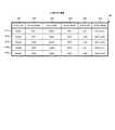
図10は、本発明の実施の形態のLU割り当て情報406の説明図である。 FIG. 10 is an explanatory diagram of the
LU割り当て情報406は、収集プログラム305が取得した情報(図7及び図8参照)に基づいて、管理サーバ110によって作成され、管理サーバ110からIPネットワーク150を介してホスト120に送信される。ホスト120は、受信したLU割り当て情報406をメモリ404に格納する。以後、ホスト120は、LU割り当て情報406を参照して、LU601に対するアクセスを管理する。具体的には、ホスト120は、LU割り当て情報406を参照して、アプリケーションプログラム405が発行したアクセス要求をそのホスト120に割り当てられたLU601に送信する。 The
図10は、図6のホスト120のLU割り当て情報406を示す。 FIG. 10 shows the
LU割り当て情報406は、オブジェクト1001、オブジェクトID1002、オブジェクト1003、オブジェクトID1004、オブジェクト1005及びオブジェクトID1006を含む。 The
オブジェクト1001は、LU601が割り当てられるホスト120のホスト名である。オブジェクトID1002は、各ホスト120に与えられる計算機システム内で一意の識別子である。図10の例では、Host1及びHost2に対して、それぞれ、識別子「H01」及び「H02」が与えられる。 The
オブジェクト1003は、ホスト120に割り当てられるLU601を含むサブシステム140のサブシステム名である。オブジェクトID1004は、各サブシステム140に与えられる計算機システム内で一意の識別子である。図10の例では、Sub1及びSub2に対して、それぞれ、識別子「S01」及び「S02」が与えられる。 An
オブジェクト1005は、ホスト120に割り当てられるLU601のLU名である。オブジェクトID1006は、各LU601に与えられる計算機システム内で一意の識別子である。図10の例では、Sub1のLU1及びLU2に対して、それぞれ、識別子「S01LU01」及び「S01LU02」が与えられる。一方、Sub2のLU1及びLU2に対して、それぞれ、識別子「S02LU01」及び「S02LU02」が与えられる。 The
LU割り当て情報406において、一つの行(エントリ)は、ホスト120からLU601に至る一つのパスに対応する。図6の例では、ホスト120からLU601に至る五つのパスが設定されている。このため、図10のLU割り当て情報406は、五つの行からなる。 In the
行1011は、Host1のWWN1からWWN5を経由してSub1のLU1に至るパスに対応する。このため、行1011には、オブジェクト1001、オブジェクト1003及びオブジェクト1005として、それぞれ、Host1、Sub1及びLU1が登録される。 A
行1012は、Host1のWWN2からWWN6を経由してSub1のLU2に至るパスに対応する。このため、行1012には、オブジェクト1001、オブジェクト1003及びオブジェクト1005として、それぞれ、Host1、Sub1及びLU2が登録される。 A
行1013は、Host2のWWN3からWWN6を経由してSub1のLU2に至るパスに対応する。このため、行1013には、オブジェクト1001、オブジェクト1003及びオブジェクト1005として、それぞれ、Host2、Sub1及びLU2が登録される。 A
行1014は、Host2のWWN3からWWN9を経由してSub2のLU1に至るパスに対応する。このため、行1014には、オブジェクト1001、オブジェクト1003及びオブジェクト1005として、それぞれ、Host2、Sub2及びLU1が登録される。 A
行1015は、Host2のWWN4からWWN9を経由してSub2のLU2に至るパスに対応する。このため、行1015には、オブジェクト1001、オブジェクト1003及びオブジェクト1005として、それぞれ、Host2、Sub2及びLU2が登録される。 A
図11は、本発明の実施の形態のサブシステム140に関するオブジェクト管理テーブル209の説明図である。 FIG. 11 is an explanatory diagram of the object management table 209 related to the
オブジェクト管理テーブル209は、収集プログラム305が取得した情報(図7及び図8参照)に基づいて、管理者用PC100によって作成され、メモリ209に格納される。オブジェクト表示プログラム207は、オブジェクト管理テーブル209を参照して、オブジェクトの表示を実行する(図16等参照)。 The object management table 209 is created by the
図2に示すように、本実施の形態の管理者用PC100のメモリ206には、オブジェクト管理テーブル209が格納される。計算機システムに複数のルートオブジェクトが存在する場合、メモリ206には、ルートオブジェクトと同じ数のオブジェクト管理テーブル209が格納される。 As shown in FIG. 2, an object management table 209 is stored in the
ルートオブジェクトとは、出力装置202の画面に表示される最上位のオブジェクトである。図1及び図6に示す本実施の形態では、ホスト120を含むカテゴリーである「ホスト(Hosts)」、及び、サブシステム140を含むカテゴリーである「サブシステム(Subsystems)」がルートオブジェクトである。したがって、本実施の形態のメモリ206には、二つのオブジェクト管理テーブル209が格納される。図11は、これらのうち、サブシステムに関するオブジェクト管理テーブル209(すなわち、「Subsystems」をルートオブジェクトとするオブジェクト管理テーブル209)を示す。一方、後で説明する図12には、ホストに関するオブジェクト管理テーブル209を示す。 The root object is the highest level object displayed on the screen of the output device 202. In this embodiment shown in FIG. 1 and FIG. 6, “Hosts” that is a category including the
オブジェクト管理テーブル209は、階層1101、最終階層1102、オブジェクト1103、オブジェクトID1104、n−1階層オブジェクトID1105、表示位置1106、表示フラグ1107、表示領域1108を含む。また、オブジェクト管理テーブル209の一つの行は、一つのオブジェクトに対応する。 The object management table 209 includes a
階層1101は、各オブジェクトの親子関係によって決定される階層を示す。すなわち、子オブジェクトは、その親オブジェクトより階層が一つ低い。オブジェクトの階層が低くなるほど、階層1101の値は大きくなる。例えば、ルートオブジェクトの階層1101は「1」であり、その子オブジェクトの階層1101は「2」であり、さらにその子オブジェクトの階層1101は「3」である。 A
最終階層1102は、各オブジェクトが子オブジェクトを持つか否かを示すフラグである。あるオブジェクトに関する最終階層1102が空欄である場合、そのオブジェクトは子オブジェクトを持つ。すなわち、そのオブジェクトを親オブジェクトとするオブジェクトが存在する。一方、あるオブジェクトに関する最終階層1102が「1」である場合、そのオブジェクトは子オブジェクトを持たない。すなわち、そのオブジェクトを親オブジェクトとするオブジェクトが存在しない。このようなオブジェクトは、最終階層のオブジェクトと記載される。 The
オブジェクト1103は、オブジェクト管理テーブル209の各行に対応するオブジェクトのオブジェクト名である。ルートオブジェクトであるサブシステムのオブジェクト1103は、「Subsystems」である。各サブシステム140のオブジェクト1103は、サブシステム名である。各パリティグループ143のオブジェクト1103は、パリティグループ名である。各LDEV602のオブジェクト1103は、LDEV名である(図6参照)。 An
オブジェクトID1104は、オブジェクト1103に対応するオブジェクトの計算機システム内で一意の識別子である。 The
ルートオブジェクトであるサブシステムのオブジェクトID1104は、「S」である。 The
Sub1及びSub2のオブジェクトID1104は、それぞれ、「S01」及び「S02」である。 The
Sub1が備えるRAID1、RAID2及びRAID3のオブジェクトID1104は、それぞれ、「S01R01」、「S01R02」及び「S01R03」である。Sub2が備えるRAID1、RAID2及びRAID3のオブジェクトID1104は、それぞれ、「S02R01」、「S02R02」及び「S02R03」である。 The
Sub1が備えるRAID1に含まれるLDEV1からLDEV3のオブジェクトID1104は、それぞれ、「S01R01L01」から「S01R01L03」である。Sub1が備えるRAID2に含まれるLDEV4からLDEV6のオブジェクトID1104は、それぞれ、「S01R02L04」から「S01R02L06」である。Sub1が備えるRAID3に含まれるLDEV7からLDEV9のオブジェクトID1104は、それぞれ、「S01R03L07」から「S01R03L09」である。 The
Sub2が備えるRAID1に含まれるLDEV1からLDEV3のオブジェクトID1104は、それぞれ、「S02R01L01」から「S02R01L03」である。Sub2が備えるRAID2に含まれるLDEV4からLDEV6のオブジェクトID1104は、それぞれ、「S02R02L04」から「S02R02L06」である。Sub2が備えるRAID3に含まれるLDEV7からLDEV9のオブジェクトID1104は、それぞれ、「S02R03L07」から「S02R03L09」である。 The
n−1階層オブジェクトID1105は、各オブジェクトの一つ上位の階層のオブジェクトのオブジェクトID1104である。 The n-1
図11のオブジェクト管理テーブル209の階層1101からn−1階層オブジェクトID1105の値は、図6に示す計算機システムに対応する。例えば、サブシステム140としてSub1が存在し、Sub1がRAID1を備え、RAID1がLDEV1を含み、そのLDEV1は子オブジェクトを持たない。 The values of the
表示位置1106は、各オブジェクトが出力装置202に表示されるときの座標である。この座標については、後で詳細に説明する。 A
表示フラグ1107は、各オブジェクトの表示の状態を示すフラグである。 A
表示フラグ1107が「0」であるオブジェクトは、表示の対象外である。すなわち、それらのオブジェクトは出力装置202に表示されない。 An object whose
表示フラグ1107が「1」であるオブジェクトは、出力装置202に通常表示される。通常表示とは、オブジェクトを強調されていない状態で表示することである。 An object whose
表示フラグ1107が「2」又は「3」であるオブジェクトは、出力装置202に強調表示される。強調表示とは、対象となるオブジェクトを、通常表示されるオブジェクトと視覚的に区別することができるように、通常表示されるオブジェクトと異なる態様によって表示することである。例えば、強調表示されるオブジェクトは、通常表示されるオブジェクトと異なる形状、大きさ又は色彩の図形によって表示されてもよい。あるいは、通常表示されるオブジェクトが通常の書体の文字によって表示され、強調表示されるオブジェクトが太字又は反転文字によって表示されてもよい。あるいは、強調表示されるオブジェクトが点滅する図形によって表示されてもよい。強調表示されるオブジェクトは、その他、通常表示とは異なる種々の態様で表示されてもよい。 An object whose
強調表示されるオブジェクトには、選択強調表示されるオブジェクトと、関連強調表示されるオブジェクトの2種類がある。表示フラグ1107が「2」であるオブジェクトが選択強調表示されるオブジェクトであり、表示フラグ1107が「3」であるオブジェクトが関連強調表示されるオブジェクトである。 There are two types of highlighted objects: objects that are selected and highlighted and objects that are highlighted. An object whose
なお、選択強調表示されるオブジェクトと、関連強調表示されるオブジェクトとは、それぞれを視覚的に区別できるように、異なる態様で(例えば、異なる図形又は異なる色彩によって)表示される。 It should be noted that the object highlighted and the object highlighted in relation are displayed in different modes (for example, by different graphics or different colors) so that they can be visually distinguished from each other.
システム管理者があるオブジェクトを選択し、その選択されたオブジェクトの子オブジェクトを出力装置202に表示することを指示したとき、その選択されたオブジェクトは、選択強調表示される。 When the system administrator selects an object and instructs the output device 202 to display child objects of the selected object, the selected object is selected and highlighted.
システム管理者があるオブジェクトを選択し、その選択されたオブジェクトに関連付けられている全ての上位のオブジェクトを表示することを指示した場合、それらの全ての上位のオブジェクトは、関連強調表示される。 When the system administrator selects a certain object and instructs to display all higher-order objects associated with the selected object, all those higher-order objects are displayed with relation highlighting.
表示領域1108は、各オブジェクトが表示される出力装置202上の領域を示す。本実施の形態の出力装置202上の領域は、第1領域及び第2領域の二つに分割される。あるいは、出力装置202上の領域は、第1領域から第3領域の三つに分割されてもよい。表示領域1108が「1」であるオブジェクトは、第1領域に表示される。表示領域1108が「2」であるオブジェクトは、第2領域に表示される。表示領域1108が「3」であるオブジェクトは、第3領域に表示される。これらの領域については、後で詳細に説明する。 A
図12は、本発明の実施の形態のホスト120に関するオブジェクト管理テーブル209の説明図である。 FIG. 12 is an explanatory diagram of the object management table 209 related to the
ホスト120に関するオブジェクト管理テーブル209は、階層1101、最終階層1102、オブジェクト1103、オブジェクトID1104、n−1階層オブジェクトID1105、表示位置1106、表示フラグ1107、表示領域1108を含む。これらの説明のうち、図11の説明と同様の部分は、記載を省略する。 The object management table 209 regarding the
ルートオブジェクトであるホストのオブジェクト1103は、「Hosts」である。ホスト120のオブジェクト1103は、ホスト名である。各LU601のオブジェクト1103は、LU名である。各LDEV602のオブジェクト1103は、LDEV名である(図6参照)。 The
ルートオブジェクトであるホストのオブジェクトID1104は、「H」である。 The
Host1及びHost2のオブジェクトID1104は、それぞれ、「H01」及び「H02」である。 The
Sub1のLU1及びLU2のオブジェクトID1104は、それぞれ、「S01LU01」及び「S01LU02」である。Sub2のLU1及びLU2のオブジェクトID1104は、それぞれ、「S02LU01」及び「S02LU02」である。 The
Sub1のLDEV1、LDEV2及びLDEV3のオブジェクトID1104は、それぞれ、「S01R01L01」、「S01R01L02」及び「S01R01L03」である。Sub2のLDEV2、LDEV3及びLDEV5のオブジェクトID1104は、それぞれ、「S02R01L02」、「S02R01L03」及び「S02R02L05」である。 The
図13は、本発明の実施の形態の表示制御テーブル210の説明図である。 FIG. 13 is an explanatory diagram of the display control table 210 according to the embodiment of this invention.
表示制御テーブル210は、オブジェクトの階層と、そのオブジェクトが表示される領域との対応関係を定義する。具体的には、オブジェクト表示プログラム207が各表示領域に表示する階層の範囲が定義される。 The display control table 210 defines the correspondence between the object hierarchy and the area where the object is displayed. Specifically, the range of the hierarchy displayed in each display area by the
図13の例では、「表示領域1」(列1301)の「開始」(行1311)に対応して「最終階層」が登録されている。一方、「表示領域1」(列1301)の「終了」(行1312)に対応して何も登録されていない。これは、表示領域1に最終階層のオブジェクト(すなわち、オブジェクト管理テーブル209の最終階層1102が「1」であるオブジェクト)のみが表示領域1に表示されることを意味する。 In the example of FIG. 13, “final hierarchy” is registered corresponding to “start” (line 1311) of “
一方、「表示領域2」(列1302)の「開始」(行1311)に対応して「第1階層」が登録され、「表示領域2」(列1302)の「終了」(行1312)に対応して「第3階層」が登録されている。これは、表示領域2に第1階層から第3階層までのオブジェクト(すなわち、オブジェクト管理テーブル209の階層1101が「1」、「2」及び「3」であるオブジェクト)のみが表示領域2に表示されることを意味する。 On the other hand, “first layer” is registered corresponding to “start” (line 1311) of “
図13の例では、「表示領域3」(列1303)に対応して何も登録されていない。これは、表示領域3が存在していないことを示す。 In the example of FIG. 13, nothing is registered corresponding to “
オブジェクト表示プログラム207は、表示制御テーブル210を参照して、オブジェクトをどの表示領域に表示するかを判定する。 The
図14は、本発明の実施の形態の表示メモリ211の説明図である。 FIG. 14 is an explanatory diagram of the
表示メモリ211は、出力装置202に表示されるべき内容を格納する。具体的には、表示メモリ211は、各表示領域の各表示位置に表示されるべき内容を格納する。図14は、例として、オブジェクト管理テーブル209が図11及び図12に示す通りであり、かつ、表示制御テーブル210が図13に示す通りである場合の表示メモリ211の内容を示す。 The
表示メモリ211上の領域は、表示領域1、表示領域2及び表示領域3に対応する領域を含み、これらの各領域は、さらに各表示位置に対応する領域を含む。これらの領域には、オブジェクト表示プログラム207によって、出力装置202に表示されるべきオブジェクトのオブジェクト名が格納される。 The area on the
図11及び図12に示すように、Subsystems、Sub1、Sub2、RAID1からRAID3、LDEV1からLDEV3及びHostsの表示フラグ1107が「1」又は「2」である。すなわち、これらのオブジェクトが表示対象であるため、これらのオブジェクトのオブジェクト名が表示メモリ211に格納される。 As shown in FIGS. 11 and 12, the
図11及び図12に示すように、Subsystems、Sub1、Sub2、RAID1からRAID3及びHostsの表示領域1108が「2」である。このため、これらのオブジェクトのオブジェクト名が表示メモリ211上の表示領域2に対応する領域に格納される。一方、LDEV1からLDEV3の表示領域1108が「1」である。このため、これらのオブジェクトのオブジェクト名が表示メモリ211上の表示領域1に対応する領域に格納される。 As shown in FIGS. 11 and 12, the
図11及び図12に示すように、Hosts、Subsystems、Sub1、RAID1、RAID2、RAID3及びSub2の表示位置1106が、それぞれ、「1」「2」「3」「4」「5」「6」「7」である。このため、これらのオブジェクトのオブジェクト名が表示メモリ211上の各表示位置に対応する領域に格納される。 As shown in FIGS. 11 and 12, the
図11に示すように、LDEV1からLDEV3の表示位置1106が、それぞれ、「1」、「2」及び「3」である。このため、これらのオブジェクトのオブジェクト名が表示メモリ211上の各表示位置に対応する領域に格納される。 As shown in FIG. 11, the
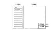
図15は、本発明の実施の形態の出力装置202に表示される画面の説明図である。 FIG. 15 is an explanatory diagram of a screen displayed on the output device 202 according to the embodiment of this invention.
図15は、例として、描画プロセッサ204が図14の表示メモリを参照して出力装置202に表示する画面を示す。 FIG. 15 shows, as an example, a screen that the
図15に示すように、出力装置202に表示される画面は、左右の二つの領域に分割されている。これらのうち、右側の領域が表示領域1であり、左側の領域が表示領域2である。この例では、表示領域3は存在しない。 As shown in FIG. 15, the screen displayed on the output device 202 is divided into two areas on the left and right. Among these, the right area is the
図14に示す表示メモリ211に従って、表示領域2の表示位置1、2、3、4、5、6及び7には、それぞれ、「Hosts」、「Subsystems」、「Sub1」、「RAID1」、「RAID2」、「RAID3」及び「Sub2」が表示される。さらに、表示領域1の表示位置1から3には、それぞれ、「LDEV1」から「LDEV3」が表示される。 According to the
なお、各オブジェクト名の周囲の破線の枠は、各オブジェクト名と表示位置との対応を明示するために表示したものである。このため、これらの枠は、実際の出力装置202には表示されなくてもよい。 A broken line frame around each object name is displayed to clearly show the correspondence between each object name and the display position. For this reason, these frames may not be displayed on the actual output device 202.
図11に示すように、Subsystems、Sub1及びRAID1の表示フラグ1107が「2」である。このため、図15において、「Subsystems」、「Sub1」及びRAID1が選択強調表示される。図15の例では、これらは太字によって表示される。これは、ルートオブジェクトであるSubsystemsが選択されてその子オブジェクトであるSub1及びSub2が表示され、Sub1が選択されてその子オブジェクトであるRAID1からRAID3が表示され、さらに、RAID1が選択されてその子オブジェクトであるLDEV1からLDEV3が表示されていることを意味する。 As shown in FIG. 11, the
次に、本実施の形態のオブジェクト表示プログラム207が実行する処理について説明する。なお、既に説明したとおり、オブジェクト表示プログラム207は、管理者用PC100のCPU203によって実行される。したがって、以下の説明においてオブジェクト表示プログラム207が実行する処理は、実際には、CPU203によって実行される。 Next, processing executed by the
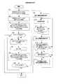
図16は、本発明の実施の形態のオブジェクト表示プログラム207が実行するオブジェクト表示処理のフローチャートである。 FIG. 16 is a flowchart of object display processing executed by the
オブジェクト表示プログラム207は、最初に、システム管理者による指示入力があったか否かを判定する(1601)。指示入力とは、例えば、入力装置201に含まれるポインティングデバイスによって、出力装置の画面上のいずれかの点を指示する操作である。さらに具体的には、システム管理者がマウスによって画面上のいずれかの点を指示してクリックしてもよい。 The
ステップ1601において、指示入力がなかったと判定された場合、オブジェクト表示プログラム207は、ステップ1601に戻り、次の指示入力を待つ。 If it is determined in
一方、ステップ1601において、指示入力があったと判定された場合、オブジェクト表示プログラム207は、指示入力の対象があるか否かを判定する(1602)。例えば、背景画面のように何も表示されていないところがポインティングデバイスによって指示された場合、指示入力の対象がなかったと判定される。一方、オブジェクト又は表示領域の境界線等がポインティングデバイスによって指示された場合、指示入力の対象があったと判定される。 On the other hand, if it is determined in
ステップ1602において、指示入力の対象がないと判定された場合、オブジェクト表示プログラム207は、ステップ1601に戻り、次の指示入力を待つ。 If it is determined in
一方、ステップ1602において、指示入力の対象があると判定された場合、オブジェクト表示プログラム207は、指示された対象がオブジェクトであるか否かを判定する(1603)。 On the other hand, when it is determined in
ステップ1603において、指示された対象がオブジェクトでないと判定された場合、オブジェクト表示プログラム207は、表示変更処理1を実行する(1606)。本実施の形態において、表示変更処理1は、表示領域の境界線が指示された場合に、その境界線を移動させる処理である。 If it is determined in
ここで、表示領域の境界線について説明する。本実施の形態の出力装置202に表示される画面は、図15に示すように、各表示領域に分割される。そして、各表示領域は、さらに二つ以上の領域に分割されてもよい。上記の表示領域の境界線とは、このように一つの表示領域が二つ以上の領域に分割された場合の分割の境界線である。この場合の画面の例については、後で説明する。 Here, the boundary line of the display area will be described. The screen displayed on the output device 202 of the present embodiment is divided into display areas as shown in FIG. Each display area may be further divided into two or more areas. The boundary line of the display area is a boundary line of division when one display area is divided into two or more areas as described above. An example of the screen in this case will be described later.
例えば、図15の表示領域2には、「Hosts」及び「Subsystems」の二つのルートオブジェクトが表示されている。この場合、表示領域2を上下の二つの領域に分割して、その一方の領域にHosts及びその下位のオブジェクトを、もう一方の領域にSubsystems及びその下位のオブジェクトを表示してもよい。この場合、それぞれの領域内で独立してスクロールが実行される。 For example, in the
このように、一つの表示領域がさらに二つ以上の領域に分割された場合、システム管理者は、その表示領域の境界線を任意の位置に移動することができる。本実施の形態のステップ1606において実行される表示変更処理1は、システム管理者が境界線を任意の位置に移動する指示を発行したときに、境界線を移動し、さらに、移動した境界線に合わせて、各オブジェクトの表示位置を更新する処理である。 As described above, when one display area is further divided into two or more areas, the system administrator can move the boundary line of the display area to an arbitrary position. The
表示変更処理1については、後で詳細に説明する(図18参照)。表示領域の境界線以外の対象が指示された場合には、別の処理が実行されてもよい。オブジェクト表示プログラム207は、表示変更処理1を実行した後、ステップ1601に戻り、次の指示入力を待つ。 The
一方、ステップ1603において、指示された対象がオブジェクトであると判定された場合、オブジェクト表示プログラム207は、関連強調表示の指示入力があったか否かを判定する(1604)。関連強調表示の指示入力とは、例えば、システム管理者が出力装置202の画面上の「関連強調表示ボタン」(後述)をポインティングデバイスによって指示することによって実行される。 On the other hand, if it is determined in
ステップ1604において、関連強調表示の指示入力がなかったと判定された場合、オブジェクト表示プログラム207は、関連強調表示をすることを要求されていないため、表示変更処理2を実行する(1607)。 If it is determined in
表示変更処理2は、ステップ1601において指示されたオブジェクトについて選択強調表示を実行する処理である。さらに、指示されたオブジェクトの子オブジェクトがまだ表示されていない場合、表示変更処理2によってそれらの子オブジェクトが表示される。一方、指示されたオブジェクトの子オブジェクトが既に表示されている場合、表示変更処理2によってそれらの子オブジェクトが表示されなくなる。表示変更処理2については、後で詳細に説明する(図19参照)。 The
オブジェクト表示プログラム207は、表示変更処理2を実行した後、ステップ1601に戻り、次の指示入力を待つ。 After executing the
ステップ1604において、関連強調表示の指示入力があったと判定された場合、オブジェクト表示プログラム207は、関連強調表示をすることを要求されている。この場合、オブジェクト表示プログラム207は、関連強調表示処理を実行する(ステップ1605)。関連強調表示処理については、後で詳細に説明する(図17参照)。オブジェクト表示プログラム207は、関連強調表示処理を実行した後、ステップ1601に戻り、次の指示入力を待つ。 If it is determined in
図17は、本発明の実施の形態のオブジェクト表示プログラム207が実行する関連強調表示処理のフローチャートである。 FIG. 17 is a flowchart of the association highlighting process executed by the
この関連強調表示処理は、オブジェクト表示処理のステップ1605において実行される(図16)。 This relation highlighting process is executed in
関連強調表示処理が開始されると、最初に、オブジェクト表示プログラム207は、指示されたオブジェクトのオブジェクトID1104を特定する(1701)。ここで、指示されたオブジェクトとは、図16のステップ1601において指示入力の対象となったオブジェクトである。このオブジェクトID1104を、以下、ID1と記載する。 When the association highlighting process is started, first, the
次に、オブジェクト表示プログラム207は、オブジェクト管理テーブル209において、指示されたオブジェクトに対応する表示フラグ1107を「2」に設定する(1702)。 Next, the
次に、オブジェクト表示プログラム207は、オブジェクトID1104がID1であるオブジェクトの親オブジェクトのうち、まだ強調表示されていないもののオブジェクトID1104を特定する(1703)。この条件に当てはまる複数のオブジェクトID1104が存在する場合、オブジェクト表示プログラム207は、それら全てのオブジェクトID1104を特定する。ここで特定されたオブジェクトID1104を、以下、ID2と記載する。 Next, the
具体的には、オブジェクト表示プログラム207は、オブジェクト管理テーブル209を参照して、オブジェクトID1104がID1であるオブジェクトを全て検索する。そして、オブジェクト表示プログラム207は、検索の結果発見されたオブジェクトのn−1階層オブジェクトID1105を参照する。そして、オブジェクト表示プログラム207は、参照されたn−1階層オブジェクトID1105と同じ値をオブジェクトID1104として持つオブジェクトを検索する。そして、オブジェクト表示プログラム207は、その検索の結果発見されたオブジェクトの表示フラグ1107を参照する。そして、オブジェクト表示プログラム207は、それらのオブジェクトのうち、表示フラグ1107が「1」以下のものを全て特定する。特定されたオブジェクトのオブジェクトID1104がID2である。 Specifically, the
例えば、ステップ1701においてSub1のLDEV1が指示された場合、そのLDEV1のオブジェクトID1104(ID1)は、S01R01L01である。オブジェクト管理テーブル209には、オブジェクトID1104がS01R01L01であるオブジェクトの登録が二つある(図11及び図12参照)。これらのオブジェクトのn−1階層オブジェクトID1105は、それぞれ、S01R01(図11)及びS01LU01(図12)である。オブジェクトID1104がS01R01であるオブジェクトRAID1の表示フラグ1107は、「2」である(図11)。一方、オブジェクトID1104がS01LU01であるオブジェクトLU1の表示フラグ1107は、「0」である(図12)。このため、ステップ1703において、S01LU01が特定され、これがID2となる。 For example, when LDEV1 of Sub1 is instructed in
次に、オブジェクト表示プログラム207は、ステップ1703において特定されたオブジェクトID1104があるか否か、言い換えると、ステップ1703において、少なくとも一つのオブジェクトのオブジェクトID1104が特定されたか否かを判定する(1704)。 Next, the
ステップ1704において、特定されたオブジェクトID1104がないと判定された場合、オブジェクトID1104がID1であるオブジェクトには、まだ強調表示されていない親オブジェクトが存在しない。この場合、関連強調表示の対象が存在しないため、オブジェクト表示プログラム207は、関連強調表示処理を終了する。 If it is determined in
一方、ステップ1704において、特定されたオブジェクトID1104があると判定された場合、オブジェクトID1104がID1であるオブジェクトには、まだ強調表示されていない親オブジェクトが存在する。この場合、その親オブジェクトを関連強調表示するため、オブジェクト表示プログラム207は、その特定されたオブジェクトID1104(すなわちID2)に対応する表示フラグ1107を「3」に設定する(1705)。 On the other hand, if it is determined in
次に、オブジェクト表示プログラム207は、ID2を新たなID1として設定する(1706)。例えば、ステップ1706の直前においてID1がS01R01L01であり、ID2がS01LU01であった場合、ステップ1706においてS01LU01が新たなID1となる。 Next, the
次に、オブジェクト表示プログラム207は、オブジェクトID1104がID1であるオブジェクトの親オブジェクトのうち、まだ強調表示されていないもののオブジェクトID1104を特定する(1707)。この処理は、ステップ1703の処理と同様であるため、説明を省略する。ここで特定されたオブジェクトID1104が、新たなID2となる。 Next, the
次に、オブジェクト表示プログラム207は、ステップ1707において特定されたオブジェクトID1104があるか否かを判定する(1708)。 Next, the
ステップ1708において、特定されたオブジェクトID1104があると判定された場合、オブジェクトID1104がID1であるオブジェクトには、まだ強調表示されていない親オブジェクトが存在する。この場合、その親オブジェクトを関連強調表示するため、処理はステップ1705に戻る。 If it is determined in
一方、ステップ1708において、特定されたオブジェクトID1104がないと判定された場合、オブジェクトID1104がID1であるオブジェクトには、まだ強調表示されていない親オブジェクトが存在しない。この時点で、関連強調表示の対象となるオブジェクトはもう残っていない。このため、オブジェクト表示プログラム207は、次に、表示位置情報更新処理を実行する(1709)。具体的には、オブジェクト表示プログラム207は、関連強調表示されるべきオブジェクトが出力装置202の画面に表示されていない場合、そのオブジェクトを画面に表示するために表示位置情報更新処理を実行する。 On the other hand, if it is determined in
例えば、ステップ1703において説明したように、S01LU01がID2として特定された場合、オブジェクトID1104がS01LU01であるオブジェクトLU1が関連強調表示される。しかし、図15に示すようにLU1が画面に表示されていない場合、LU1を関連強調表示するためには、ルートオブジェクトHostsの子オブジェクトであるHost1及びHost2を表示し、さらに、Host1の子オブジェクトであるLU1及びLU2を表示する必要がある。ステップ1709では、このように、関連強調表示されるべきオブジェクトが新たに表示される。 For example, as described in
ここで実行される表示位置情報更新処理については、後で詳細に説明する(図21等参照)。出力装置202の画面が複数の表示領域に分割されている場合、各表示領域について図21等に示す表示位置情報更新処理が実行される。例えば、図15に示すように、画面が表示領域1及び表示領域2に分割されている場合、図11及び図12に示すオブジェクト管理テーブル209の表示領域1108が「2」のオブジェクトについて図21等に示す表示位置情報更新処理が実行される。さらに、表示領域1108が「1」のオブジェクトについて同様に表示位置情報更新処理が実行される。 The display position information update process executed here will be described in detail later (see FIG. 21 and the like). When the screen of the output device 202 is divided into a plurality of display areas, the display position information update process shown in FIG. 21 and the like is executed for each display area. For example, as shown in FIG. 15, when the screen is divided into the
ただし、一つの表示領域がさらに境界線によって分割されている場合、分割されたそれぞれの領域について図21等に示す表示位置情報更新処理が実行される(図23参照)。 However, when one display area is further divided by the boundary line, the display position information update process shown in FIG. 21 and the like is executed for each divided area (see FIG. 23).
なお、表示位置情報更新処理によって、表示フラグ1107が「1」以上の全てのオブジェクトについて表示位置が更新される。 Note that the display position is updated for all objects having the
次に、オブジェクト表示プログラム207は、画面表示処理を実行する(1710)。画面表示処理とは、ステップ1709において設定された位置情報に従って、各オブジェクトを出力装置202の画面上に表示する処理である。 Next, the
次に、オブジェクト表示プログラム207は、表示フラグ1107が「3」であるオブジェクト(すなわち、関連強調表示されたオブジェクト)が全て画面に表示されたか否かを判定する(1711)。計算機システム内のオブジェクトの数が増加すると、全てのオブジェクトを一つの画面に同時に表示することができなくなる。この場合、全てのオブジェクトを表示するためには、画面をスクロールする必要がある。ステップ1711では、全てのオブジェクトを同時に表示できないことが原因で、まだ画面に表示されていない関連強調表示されたオブジェクトが存在するか否かが判定される。 Next, the
具体的には、オブジェクト管理テーブル209の表示フラグ1107が「3」であり、かつ、表示位置1106の値が表示メモリ211の表示位置の最大値(図14の例では、「11」)より大きいオブジェクトが存在する場合、まだ画面に表示されていない関連強調表示されたオブジェクトが存在すると判定される。 Specifically, the
ステップ1711において、全ての関連強調表示されたオブジェクトが画面に表示されたと判定された場合、オブジェクト表示プログラム207は、関連強調表示処理を終了する。 If it is determined in
一方、ステップ1711において、全ての関連強調表示されたオブジェクトが画面に表示されていないと判定された場合、少なくとも一つの関連強調表示されたオブジェクトがまだ画面に表示されていない。この場合、オブジェクト表示プログラム207は、表示位置情報更新処理を実行する(1712)。 On the other hand, if it is determined in
ステップ1712において、オブジェクト表示プログラム207は、表示位置情報更新処理を実行することによって、出力装置202の画面を自動的にスクロールして全ての関連強調表示されたオブジェクトを表示してもよい。あるいは、オブジェクト表示プログラム207は、システム管理者が入力するスクロールの指示に従って、順次画面をスクロールしてもよい。例えば、まだ表示されていない関連強調表示されたオブジェクトが二つある場合、システム管理者がスクロールの指示を1回入力すると、二つのうち一つの関連強調表示されたオブジェクトが表示されるまでスクロールが実行されてもよい。システム管理者がスクロールの指示をもう1回入力すると、もう一つの関連強調表示されたオブジェクトが表示されるまでスクロールが実行されてもよい。 In
具体的には、ステップ1712において、各オブジェクトの位置情報(すなわち、オブジェクト管理テーブル209の表示位置1106)が更新される。表示位置1106の値が順次1ずつ減少することによって、各オブジェクトの画面上の表示位置が上方向に移動する。 Specifically, in
なお、ステップ1712においてオブジェクトの位置情報が更新され、その後、ステップ1710において、更新された位置情報に従って画面表示が更新される。その結果、スクロールが実行される。 In
表示フラグ1107が「3」であり、かつ、最も大きい表示位置1106を持つオブジェクトの表示位置1106の値が表示メモリ211の表示位置の最大値以下になるまで、ステップ1712及びステップ1710によるスクロールが実行される。その結果、全ての関連強調表示されたオブジェクトが画面に順次表示される。 Scrolling by
次に、オブジェクト表示プログラム207は、表示フラグ1107が「0」でない第1階層のオブジェクトのうち、表示されていないものがあるか否かを判定する(1713)。ここで、第1階層のオブジェクトとは、ルートオブジェクトのことである。例えば、図15において、Sub2の下にも多くのオブジェクトが表示された場合、それらのオブジェクトを表示するために画面をスクロールすることによって、ルートオブジェクト(例えば、Hosts)が画面の外側に追い遣られた結果、いくつかのルートオブジェクトが画面に表示されない場合がある。ステップ1713では、このようにして画面に表示されなくなったルートオブジェクトがあるか否かが判定される。 Next, the
具体的には、オブジェクト管理テーブル209の表示フラグ1107が「1」以上であり、かつ、表示位置1106の値が表示メモリ211の表示位置の最小値(図14の例では、「1」)より小さいルートオブジェクトが存在する場合、画面に表示されなくなったルートオブジェクトが存在すると判定される。 Specifically, the
ステップ1713において、表示されていない第1階層のオブジェクトがないと判定された場合、ステップ1712において更新された位置情報に従って画面表示を実行するため、ステップ1710に戻る。 If it is determined in
一方、ステップ1713において、表示されていない第1階層のオブジェクトがないと判定された場合、その表示されていない第1階層のオブジェクトを表示領域3に表示することが望ましい。システム管理者が全てのルートオブジェクトを容易に把握できることが望ましいためである。 On the other hand, if it is determined in
ここで、表示領域3とは、表示領域2の左側に設けられる領域である。図15に示すように、表示領域3が存在しない場合、表示領域2の左側に新たに表示領域3を設ける必要がある。このため、オブジェクト表示プログラム207は、表示領域3が既に存在しているか否かを判定する(1714)。 Here, the
ステップ1714において、表示領域3が存在していると判定された場合、オブジェクト表示プログラム207は、表示領域3を新たに設ける必要がない。このため、処理はステップ1710に戻る。 If it is determined in
一方、ステップ1714において、表示領域3が存在していないと判定された場合、オブジェクト表示プログラム207は、表示領域3を新たに設ける必要がある。このため、オブジェクト表示プログラム207は、表示領域3を新たに設け、表示位置情報更新処理を実行する(1715)。ステップ1715では、ステップ1709と同様に、図21等に示す表示位置情報更新処理が実行される。 On the other hand, if it is determined in
オブジェクト表示プログラム207は、表示領域3を新たに設けるとき、表示制御テーブル210を更新する。図13の例では、表示領域2に第1階層から第3階層までが表示される。ここで、表示領域3が新たに設定されると、表示領域3に対応する行1311に「第1階層」が登録される。これは、出力装置202の画面に新たに表示領域3が設けられ、その表示領域3にルートオブジェクトが表示されることを意味する。 The
その後、オブジェクト表示プログラム207は、ステップ1712及びステップ1715において更新された位置情報に従って画面表示を実行するために、ステップ1710に戻る。 Thereafter, the
上記のステップ1711から1715の処理をまとめると、次のようになる。 The processing of
関連強調表示されるべきオブジェクトの表示位置1106が出力装置202の表示領域の表示位置の最大値より大きい場合、オブジェクト表示プログラム207は、当該オブジェクトの表示位置1106が当該表示領域の表示位置の最大値以下となるまで、各オブジェクトの表示位置1106の値を減少する。 When the
ルートオブジェクトの表示位置1106が、表示領域のスクロールの結果、表示領域の表示位置の最小値より小さくなったとき、オブジェクト表示プログラム207は、出力装置202に新たな表示領域(表示領域3)を設定し、当該新たに設定された表示領域に当該ルートオブジェクトを表示する。さらに具体的には、オブジェクト表示プログラム207は、表示制御テーブルに、新たな表示領域(表示領域3)に対応して、ルートオブジェクトを登録することによって、出力装置202に当該表示領域3を設定する。 When the
図18は、本発明の実施の形態のオブジェクト表示プログラム207が実行する表示変更処理1のフローチャートである。 FIG. 18 is a flowchart of the
表示変更処理1は、オブジェクト表示処理のステップ1606において実行される(図16)。 The
オブジェクト表示プログラム207は、最初に、システム管理者による指示入力があったか否かを判定する(1801)。ここで、指示入力とは、例えば、システム管理者が入力装置201に含まれるポインティングデバイスを操作して表示領域の境界線を任意の位置に設定する指示をすることである。 The
ステップ1801において、指示入力がなかったと判定された場合、オブジェクト表示プログラム207は、ステップ1801に戻り、次の指示入力を待つ。 If it is determined in
一方、ステップ1801において、指示入力があったと判定された場合、オブジェクト表示プログラム207は、指示入力によって指示された位置に、境界線を設定する(1802)。その結果、境界線が指示された位置に移動する。 On the other hand, if it is determined in
次に、オブジェクト表示プログラム207は、表示位置情報更新処理を実行する(1803)。この表示位置情報更新処理によって、移動した境界線に合わせて各オブジェクトの表示位置が更新される。ステップ1803では、図17のステップ1709と同様、図21等に示す表示位置情報更新処理が実行される。ただし、処理の負荷を減らすため、境界線が設定された表示領域のみを対象として、図21等に示す表示位置情報更新処理が実行される。 Next, the
次に、オブジェクト表示プログラム207は、画面表示処理を実行する(1804)。この画面表示処理は、ステップ1803において更新された位置情報に従って、各オブジェクトを出力装置202の画面上に表示する処理である。 Next, the
オブジェクト表示プログラム207は、ステップ1804を実行すると、表示変更処理1を終了する。 When executing
図19は、本発明の実施の形態のオブジェクト表示プログラム207が実行する表示変更処理2のフローチャートである。 FIG. 19 is a flowchart of the
表示変更処理2は、オブジェクト表示処理のステップ1607において実行される(図16)。 The
表示変更処理2が開始されると、最初に、オブジェクト表示プログラム207は、指示されたオブジェクトのオブジェクトID1104を特定する(1901)。ここで、指示されたオブジェクトとは、図16のステップ1601において指示入力の対象となったオブジェクトである。このオブジェクトID1104を、以下、ID1と記載する。 When the
次に、オブジェクト表示プログラム207は、オブジェクト管理テーブル209において、指示されたオブジェクトに対応する表示フラグ1107を「2」に設定する(1702)。 Next, the
次に、オブジェクト表示プログラム207は、ID1及び指示されたオブジェクトの表示位置に基づいて、オブジェクト管理テーブル209を特定する(1903)。メモリ206には、ルートオブジェクトと同じ数のオブジェクト管理テーブル209が格納される。図6の例では、ルートオブジェクト「Subsystems」に関するオブジェクト管理テーブル209(図11)、及び、ルートオブジェクト「Hosts」に関するオブジェクト管理テーブル209(図12)が存在する。ステップ1903では、指示されたオブジェクトがこれらの管理テーブルのどちらに属するかが特定される。例えば、図15においてRAID1が指示された場合、ステップ1903において、サブシステムに関するオブジェクト管理テーブル209が特定される。 Next, the
さらに、ステップ1903において、オブジェクト表示プログラム207は、特定されたオブジェクト管理テーブル209を参照して、指示されたオブジェクトの子オブジェクトのオブジェクトID1104を特定する。具体的には、オブジェクト表示プログラム207は、特定されたオブジェクト管理テーブル209のn−1階層オブジェクトID1105において、ID1を検索する。その結果発見されたID1に対応するオブジェクトID1104を、指示されたオブジェクトの子オブジェクトのオブジェクトID1104として特定する。以下、ステップ1903において特定されたオブジェクトIDをID2と記載する。 Further, in
次に、オブジェクト表示プログラム207は、ステップ1903において特定されたオブジェクトID1104があるか否か、言い換えると、ステップ1903において、少なくとも一つのオブジェクトのオブジェクトID1104が特定されたか否かを判定する(1904)。 Next, the
ステップ1904において、特定されたオブジェクトID1104がないと判定された場合、指示されたオブジェクトの子オブジェクトが存在しない。すなわち、指示されたオブジェクトの子オブジェクトを表示することができないため、オブジェクト表示プログラム207は、表示変更処理2を終了する。 If it is determined in
一方、ステップ1904において、特定されたオブジェクトID1104があると判定された場合、指示されたオブジェクトの一つ以上の子オブジェクトが存在する。この場合、オブジェクト表示プログラム207は、それらの子オブジェクトが既に表示されているか否かを判定する(1905)。 On the other hand, if it is determined in
ステップ1905において、子オブジェクトが既に表示されていると判定された場合、オブジェクト表示プログラム207は、その表示を取り消す(1906)。具体的には、オブジェクト表示プログラム207は、指定されたオブジェクトの子オブジェクトの表示フラグ1107を「0」にする。 If it is determined in
一方、ステップ1905において、子オブジェクトがまだ表示されていないと判定された場合、オブジェクト表示プログラム207は、子オブジェクトを表示する(1907)。具体的には、オブジェクト表示プログラム207は、指定されたオブジェクトの子オブジェクトの表示フラグ1107を「1」にする。 On the other hand, if it is determined in
次に、オブジェクト表示プログラム207は、表示位置情報更新処理を実行する(1908)。この表示位置情報更新処理によって、新たに表示されるオブジェクトの表示位置が決定する。さらに、オブジェクトの新たな表示又は表示の取り消しによって移動するオブジェクトの表示位置が更新される。ステップ1908では、図17のステップ1709と同様、図21等に示す表示位置情報更新処理が実行される。 Next, the
次に、オブジェクト表示プログラム207は、画面表示処理を実行する(1909)。この画面表示処理は、ステップ1908において更新された位置情報に従って、各オブジェクトを出力装置202の画面上に表示する処理である。 Next, the
オブジェクト表示プログラム207は、ステップ1909を実行すると、表示変更処理2を終了する。 When executing the
次に、表示位置情報更新処理について、図20から図22を参照して説明する。 Next, the display position information update process will be described with reference to FIGS.
図20は、本発明の実施の形態の表示位置情報更新処理の説明におけるオブジェクトの記載方法の説明図である。 FIG. 20 is an explanatory diagram of an object description method in the description of the display position information update processing according to the embodiment of this invention.
以下の説明において、第n階層のj番目のオブジェクトは、O(n、j)と記載される。O(1、1)がルートオブジェクト(すなわち、第1階層の1番目のオブジェクト)である。O(2、1)及びO(2、2)はルートオブジェクトの子オブジェクトである。O(3、1)及びO(3、2)はO(2、1)の子オブジェクトである。O(4、1)及びO(4、2)はO(3、1)の子オブジェクトである。第1階層を除く各階層には、任意の数のオブジェクトが存在し得る。 In the following description, the jth object in the nth layer is described as O (n, j). O (1, 1) is a root object (that is, the first object in the first hierarchy). O (2,1) and O (2,2) are child objects of the root object. O (3, 1) and O (3, 2) are child objects of O (2, 1). O (4, 1) and O (4, 2) are child objects of O (3, 1). There can be any number of objects in each layer except the first layer.
例えば、図11において、SubsystemsがO(1、1)である。Sub1及びSub2がそれぞれO(2、1)及びO(2、2)である。Sub1が備えるRAID1からRAID3がそれぞれO(3、1)からO(3、3)である。Sub1が備えるRAID1に含まれるLDEV1からLDEV3がそれぞれO(4、1)からO(4、3)である。 For example, in FIG. 11, Subsystems is O (1, 1). Sub1 and Sub2 are O (2, 1) and O (2, 2), respectively. RAID1 to RAID3 included in Sub1 are O (3, 1) to O (3, 3), respectively. LDEV1 to LDEV3 included in RAID1 included in Sub1 are O (4, 1) to O (4, 3), respectively.
図21は、本発明の実施の形態のオブジェクト表示プログラム207が実行する表示位置情報更新処理のフローチャートである。 FIG. 21 is a flowchart of the display position information update process executed by the
表示位置情報更新処理は、関連強調表示処理のステップ1709、ステップ1715、表示変更処理1のステップ1803、及び、表示変更処理2のステップ1908において実行される(図17、図18及び図19)。表示位置情報更新処理は、各オブジェクトの位置情報、すなわち、各オブジェクトの表示位置1106を更新する処理である。 The display position information update process is executed in
表示位置情報更新処理が開始されると、オブジェクト表示プログラム207は、最初に、処理の対象となる表示領域の位置情報をクリアする(2101)。具体的には、オブジェクト管理テーブル209において、処理の対象の表示領域1108に対応するオブジェクトの表示位置1106がクリアされる。 When the display position information update process is started, the
次に、オブジェクト表示プログラム207は、n、i及びjの値を「1」に初期設定する(2102)。ここで、nはO(n、j)が属する階層であり、jはその階層におけるO(n、j)の番号である。一方、iは、O(n、j)の表示位置1106として設定されるべき値である。 Next, the
次に、オブジェクト表示プログラム207は、n=1であるか否かを判定する(2103)。 Next, the
ステップ2103において、n=1であると判定された場合、O(n、j)はルートオブジェクトである。この場合、オブジェクト表示プログラム207は、O(n、j)について位置情報設定処理を実行する(2104)。その結果、O(n、j)の表示位置1106が「i」と設定され、その後、iの値が1だけ増加される。なお、ステップ2104、後述するステップ2110及びステップ2117において実行される位置情報設定処理については、後で詳細に説明する(図22参照)。 If it is determined in
次に、オブジェクト表示プログラム207は、OnをO(n、j)とし、nの値を1だけ増加させる(2105)。例えば、n=1、j=1のとき、ステップ2105において、O1がO(1、1)となり、n=2となる。 Next, the
オブジェクト表示プログラム207は、ステップ2105を実行した後、次の階層について処理するために、ステップ2103に戻る。 After executing
ステップ2103において、n=1でないと判定された場合、O(n、j)はルートオブジェクトでない。この場合、オブジェクト表示プログラム207は、O(n、j)が存在するか否かを判定する(2106)。 If it is determined in
ステップ2106において、O(n、j)が存在すると判定された場合、オブジェクト表示プログラム207は、O(n、j)が最終階層であるか否かを判定する(2107)。具体的には、オブジェクト表示プログラム207は、オブジェクト管理テーブル209において、O(n、j)に対応する最終階層1102が「1」であるか否かを判定する。 If it is determined in
ステップ2107において、O(n、j)が最終階層でないと判定された場合、オブジェクト表示プログラム207は、O(n、j)がOmの子オブジェクトであるか否かを判定する(2114)。ここで、m=n−1である。例えば、n=2の場合、ステップ2114において、O(2、j)がO1の子オブジェクトであるか否かが判定される。オブジェクト表示プログラム207は、オブジェクト管理テーブル209のオブジェクトID1104及びn−1階層オブジェクトID1105を参照してステップ2114の判定を実行する。 If it is determined in
ステップ2114において、O(n、j)がOmの子オブジェクトでないと判定された場合、処理は後述するステップ2116に進む。 If it is determined in
一方、ステップ2114において、O(n、j)がOmの子オブジェクトであると判定された場合、オブジェクト表示プログラム207は、O(n、j)について位置情報設定処理が既に実行されているか否かを判定する(2115)。 On the other hand, if it is determined in
ステップ2115において、O(n、j)について位置情報設定処理が既に実行されていると判定された場合、O(n、j)の表示位置1106が既に設定されている。このため、オブジェクト表示プログラム207は、O(n、j)と同じ階層の次のオブジェクトの表示位置1106を設定するために、jの値を1だけ増加させて(2116)、ステップ2106に戻る。 If it is determined in
一方、ステップ2115において、O(n、j)について位置情報設定処理がまだ実行されていないと判定された場合、O(n、j)の表示位置1106がまだ設定されていない。このため、オブジェクト表示プログラム207は、O(n、j)について位置情報設定処理を実行する(2117)。その結果、O(n、j)の表示位置1106が「i」と設定され、その後、iの値が1だけ増加される。 On the other hand, if it is determined in
次に、オブジェクト表示プログラム207は、OnをO(n、j)とし、nの値を1だけ増加させる(2118)。これは、ステップ2105と同様である。さらに、オブジェクト表示プログラム207は、ステップ2118において、jの値を「1」とする。そして、処理はステップ2106に戻る。 Next, the
ステップ2107において、O(n、j)が最終階層であると判定された場合、オブジェクト表示プログラム207は、kの値を「1」に設定する(2108)。ここで、kは、jと同様、オブジェクトの階層内の番号である。 If it is determined in
次に、オブジェクト表示プログラム207は、O(n、k)がOmの子オブジェクトであるか否かを判定する(2109)。ステップ2114と同様、m=n−1である。 Next, the
ステップ2109において、O(n、k)がOmの子オブジェクトでないと判定された場合、処理は後述するステップ2111に進む。 If it is determined in
一方、ステップ2109において、O(n、k)がOmの子オブジェクトであると判定された場合、オブジェクト表示プログラム207は、O(n、k)について位置情報設定処理を実行する(2110)。その結果、O(n、k)の表示位置1106が「i」と設定され、その後、iの値が1だけ増加される。 On the other hand, if it is determined in
次に、オブジェクト表示プログラム207は、kの値を1だけ増加させる(2111)。 Next, the
次に、オブジェクト表示プログラム207は、O(n、k)が存在するか否かを判定する(2112)。 Next, the
ステップ2112において、O(n、k)が存在すると判定された場合、第n階層(すなわち最終階層)には、Omの子オブジェクトであって、かつ、まだ位置情報設定処理が実行されていないオブジェクトが存在する可能性がある。このため、処理はステップ2109に戻る。 If it is determined in
一方、ステップ2112において、O(n、k)が存在しないと判定された場合、第n階層のうち、Omの全ての子オブジェクトについて、位置情報設定処理が実行された。この場合、オブジェクト表示プログラム207は、nの値を1だけ減少させ、jの値を「1」に設定して(2113)、ステップ2106に戻る。 On the other hand, if it is determined in
ステップ2106において、O(n、j)が存在しないと判定された場合、オブジェクト表示プログラム207は、nの値を1だけ減少させ、jの値を1とする(2119)。 If it is determined in
次に、オブジェクト表示プログラム207は、n=1であるか否かを判定する(2120)。 Next, the
ステップ2120において、n=1でないと判定された場合、まだ表示位置1106が設定されていないオブジェクトが存在する可能性がある。このため、残りのオブジェクトの表示位置1106を設定するために、処理はステップ2106に戻る。 If it is determined in
一方、ステップ2120において、n=1であると判定された場合、全てのオブジェクトの表示位置1106が設定された。このため、オブジェクト表示プログラム207は、表示位置情報更新処理を終了する。 On the other hand, if it is determined in
図22は、本発明の実施の形態のオブジェクト表示プログラム207が実行する位置情報設定処理のフローチャートである。 FIG. 22 is a flowchart of the position information setting process executed by the
位置情報設定処理は、表示位置情報更新処理のステップ2104、2110及び2117において実行される(図21参照)。 The position information setting process is executed in
なお、位置情報設定処理が図21のステップ2110において実行される場合、以下の処理において、kの値がjに代入される。 When the position information setting process is executed in
位置情報設定処理が開始されると、オブジェクト表示プログラム207は、O(n、j)が表示位置情報更新処理の対象の表示領域内にあるか否かを判定する(2201)。例えば、表示領域2を対象として表示位置情報更新処理が実行されている場合、オブジェクト表示プログラム207は、表示制御テーブル210(図13)を参照して、nが「1」から「3」までのいずれかであるか否かを判定する。あるいは、オブジェクト表示プログラム207は、オブジェクト管理テーブル209を参照して、O(n、j)に対応する表示領域1108が「2」であるか否かを判定してもよい。 When the position information setting process is started, the
ステップ2201において、O(n、j)が表示位置情報更新処理の対象の表示領域内にないと判定された場合、O(n、j)の表示位置1106を更新する必要がない。このため、オブジェクト表示プログラム207は、位置情報設定処理を終了する。 If it is determined in
一方、ステップ2201において、O(n、j)が表示位置情報更新処理の対象の表示領域内にあると判定された場合、オブジェクト表示プログラム207は、オブジェクト管理テーブル209を参照して、O(n、j)に対応する表示フラグ1107が「1」以上であるか否かを判定する(2202)。 On the other hand, if it is determined in
ステップ2202において、O(n、j)に対応する表示フラグ1107が「1」以上でない(すなわち、表示フラグ1107が「0」である)と判定された場合、O(n、j)は、画面への表示の対象でない。この場合、オブジェクト表示プログラム207は、O(n、j)の表示位置1106を更新する必要がない。したがって、オブジェクト表示プログラム207は、位置情報設定処理を終了する。 If it is determined in
一方、ステップ2202において、O(n、j)に対応する表示フラグ1107が「1」以上であると判定された場合、O(n、j)は、画面への表示の対象である。この場合、オブジェクト表示プログラム207は、O(n、j)の表示位置1106として「i」を設定する(2203)。 On the other hand, if it is determined in
次に、オブジェクト表示プログラム207は、iの値を1だけ増加させる(2204)。そして、オブジェクト表示プログラム207は、位置情報設定処理を終了する。 Next, the
上記図21等に示す表示位置情報更新処理は、出力装置202の画面の各表示領域を対象として実行される。しかし、各表示領域がさらに境界線によって分割されている場合、その分割された領域ごとに図21等に示す表示位置情報更新処理が実行される。 The display position information update process shown in FIG. 21 and the like is executed for each display area of the screen of the output device 202. However, when each display area is further divided by a boundary line, the display position information update process shown in FIG. 21 or the like is executed for each divided area.
図23は、本発明の実施の形態の出力装置202に表示される画面が分割された場合の表示メモリ211の説明図である。 FIG. 23 is an explanatory diagram of the
図23において、図14と同様の部分については、説明を省略する。 In FIG. 23, the description of the same parts as in FIG. 14 is omitted.
図23において、破線の枠内に表示された数字は、オブジェクトの表示位置である。例えば、オブジェクト管理テーブル209の表示位置1106が「1」であるオブジェクトのオブジェクト名は、図23において、「1」が表示された枠が示す領域に格納される。 In FIG. 23, the number displayed in a broken-line frame is the display position of the object. For example, the object name of the object whose
図23の例では、表示領域2が境界線2301によって二つの領域に分割される。境界線2301の上側の領域を表示領域2A、下側の領域を表示領域2Bと記載する。出力装置202の画面の表示領域2が境界線によって上下に分割される。そして、表示メモリ211の表示領域2Aに格納されたオブジェクト名が、画面の表示領域2の上側の領域に表示される。一方、表示メモリ211の表示領域2Bに格納されたオブジェクト名が、画面の表示領域2の下側の領域に表示される。 In the example of FIG. 23, the
表示領域2Aの一番上の枠が示す領域の表示位置は「1」である。その下に続く領域の表示位置は、「2」、「3」及び「4」と、下に行くほど値が大きくなる。 The display position of the area indicated by the uppermost frame of the display area 2A is “1”. The display position of the area that follows is “2”, “3”, and “4”, and the value increases as it goes down.
表示領域2Bの一番上の枠が示す領域の表示位置も「1」である。その下に続く領域の表示位置も、表示領域2Aと同様に、下に行くほど値が大きくなる。 The display position of the area indicated by the uppermost frame of the display area 2B is also “1”. Similarly to the display area 2A, the display position of the area that follows the area increases as it goes down.
このように、表示領域2が二つに分割されている場合、図21等に示す表示位置情報更新処理は、表示領域2A及び表示領域2Bのそれぞれについて実行される。 Thus, when the
次に、本実施の形態によって表示される画面の例を説明する。 Next, an example of a screen displayed according to the present embodiment will be described.
図24は、本発明の実施の形態の出力装置202に表示される画面の例の説明図である。 FIG. 24 is an explanatory diagram illustrating an example of a screen displayed on the output device 202 according to the embodiment of this invention.
図24に示す画面は、表示領域1及び表示領域2からなり、表示領域2にルートオブジェクト「Hosts」及び「Subsysytems」のみが表示されている。 The screen illustrated in FIG. 24 includes a
表示領域1には、関連強調表示ボタン2401及び表示変更ボタン2402が表示されている。これらのボタンについては、後で説明する(図26及び図27参照)。なお、これらのボタンは、画面上の任意の余白に表示される。したがって、これらのボタンは、いずれの表示領域に表示されてもよい。 In the
図25は、本発明の実施の形態の出力装置202に表示される選択強調表示された画面の例の説明図である。 FIG. 25 is an explanatory diagram of an example of a selection highlighted screen displayed on the output device 202 according to the embodiment of this invention.
図24において、システム管理者が「Subsystem」をポインティングデバイスによって指示すると、ルートオブジェクトSubsystemの子オブジェクトであるSub1及びSub2が表示領域2に表示される。ここで、ポインティングデバイスによる指示とは、マウスによってカーソルを「Subsystem」の上に置き、クリックする操作であってもよいし、他の操作であってもよい。以下の説明において、「指示する」とは、このようなポインティングデバイスによる指示を意味する。 In FIG. 24, when the system administrator instructs “Subsystem” with the pointing device, Sub1 and Sub2 which are child objects of the root object Subsystem are displayed in the
さらに、システム管理者が「Sub1」を指示すると、Sub1の子オブジェクトであるRAID1、RAID2及びRAID3が表示領域2に表示される。さらに、システム管理者が「RAID1」を指示すると、RAID1の子オブジェクトであるLDEV1、LDEV2及びLDEV3が表示領域1に表示される(図25)。 Further, when the system administrator instructs “Sub1”, RAID1, RAID2 and RAID3 which are child objects of Sub1 are displayed in the
この場合、Subsystem、Sub1及びRAID1の子オブジェクトが表示されているため、これらのオブジェクトが選択強調表示されている。図25の例では、これらのオブジェクトは太字によって表示されている。 In this case, since the child objects of Subsystem, Sub1, and RAID1 are displayed, these objects are selected and highlighted. In the example of FIG. 25, these objects are displayed in bold.
図25に示す画面が表示されているときのオブジェクト管理テーブル209、表示制御テーブル210及び表示メモリ211の内容は、図11から図14に示す通りである。 The contents of the object management table 209, the display control table 210, and the
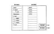
図26は、本発明の実施の形態の出力装置202に表示される関連強調表示された画面の例の説明図である。 FIG. 26 is an explanatory diagram illustrating an example of a screen on which the relation is highlighted, which is displayed on the output device 202 according to the embodiment of this invention.
図25において、システム管理者がLDEV1を指示し、さらに、関連強調表示ボタン2401を指示すると、LDEV1に関連する上位の全てのオブジェクトが図26に示すように関連強調表示される。関連強調表示の手順は、図16のステップ1604及びステップ1605、並びに、図17等に示す通りである。 In FIG. 25, when the system administrator designates LDEV1 and further designates the relation
上記のように、RAID1がLDEV1の親オブジェクトであり、Sub1がRAID1の親オブジェクトであり、SubsystemsがSub1の親オブジェクトである。すなわち、これらのオブジェクトは、LDEV1に関連する上位のオブジェクトである。さらに、図12に示すように、LU1がLDEV1の親オブジェクトであり、Host1がLU1の親オブジェクトであり、HostsがHost1の親オブジェクトである。すなわち、Hosts、Host1及びLU1もLDEV1に関連する上位オブジェクトである。このため、これらの上位オブジェクトが関連強調表示される。ただし、既に選択強調表示されているオブジェクトは、関連強調表示されない(図17のステップ1703及び1707参照)。 As described above, RAID1 is a parent object of LDEV1, Sub1 is a parent object of RAID1, and Subsystems is a parent object of Sub1. That is, these objects are high-order objects related to LDEV1. Further, as shown in FIG. 12, LU1 is a parent object of LDEV1, Host1 is a parent object of LU1, and Hosts is a parent object of Host1. That is, Hosts, Host1, and LU1 are higher-level objects related to LDEV1. For this reason, these high-order objects are highlighted in relation. However, objects that have already been selected and highlighted are not displayed with related highlights (see
その結果、図26に示すように、Hosts、Host1及びLU1が関連強調表示される。図26の例では、これらのオブジェクトを斜体字によって表示している。その結果、これらのオブジェクトは選択強調表示されたオブジェクトと異なる態様で表示される。しかし、例えば、関連強調表示されるオブジェクトは、選択強調表示されるオブジェクトと異なる色彩又は異なる図形によって表示されてもよい。 As a result, as shown in FIG. 26, Hosts, Host1, and LU1 are displayed with relation highlighting. In the example of FIG. 26, these objects are displayed in italics. As a result, these objects are displayed in a different manner from the objects that are selected and highlighted. However, for example, the object that is highlighted in relation may be displayed in a different color or a different graphic than the object that is highlighted in selection.
なお、図25において、Hostsの下位のHost1及びLU1は表示されていない。このため、これらのオブジェクトを関連強調表示するために、これらのオブジェクトが表示領域2の「Hosts」の下に表示される。さらに、Subsystem及びその下位のオブジェクトの表示位置が二つ下に変更される(図17のステップ1709参照)。 In FIG. 25, Host1 and LU1 that are lower than Hosts are not displayed. For this reason, these objects are displayed under “Hosts” in the
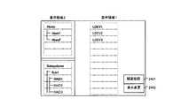
図27は、本発明の実施の形態の出力装置202に表示される表示領域3を含む画面の例の説明図である。 FIG. 27 is an explanatory diagram illustrating an example of a screen including the
システム管理者が表示変更ボタン2402を指示すると、表示領域2の左側に表示領域3が表示される。あるいは、存在する全てのルートオブジェクトを表示領域2に表示することができなくなったときに、自動的に表示領域3が表示されてもよい(図17のステップ1715参照)。 When the system administrator instructs the
例えば、「Hosts」の下位の多数のオブジェクトが表示領域2に表示された結果、「Subsystems」が表示領域2に表示されなくなる場合がある。この場合、システム管理者は、表示領域2をスクロールすることによって「Subsystems」を表示することができる。しかし、その結果、「Hosts」が表示領域2の外に追い遣られ、表示されなくなる場合がある。このとき、表示領域3が表示され、そこに「Hosts」が表示される。システム管理者がさらにスクロールを実行することによって「Subsystems」までもが表示領域2の外に追い遣られると、表示領域3に「Subsystems」の表示が追加される。 For example, “Subsystems” may not be displayed in the
あるいは、表示領域3が最初に表示されたときに、全てのルートオブジェクトが表示領域3に自動的に表示されてもよい。 Alternatively, all the root objects may be automatically displayed in the
図27の例は、表示領域3に「Hosts」及び「Subsystems」が表示された画面を示す。 The example of FIG. 27 shows a screen on which “Hosts” and “Subsystems” are displayed in the
図28は、本発明の実施の形態の出力装置202に表示される分割された画面の例の説明図である。 FIG. 28 is an explanatory diagram illustrating an example of a divided screen displayed on the output device 202 according to the embodiment of this invention.
図28は、表示領域2が境界線によって上下に分割され、分割されたそれぞれの領域にオブジェクトが表示された画面を示す。分割された上下の領域には、同じ階層に属するオブジェクト及びその下位のオブジェクトが表示される。 FIG. 28 shows a screen in which the
図28の例では、分割された上側の領域に、ルートオブジェクトであるHosts及びその下位のオブジェクト(Host1等)が表示される。一方、下側の領域には、ルートオブジェクトであるSubsysytems及びその下位のオブジェクト(Sub1等)が表示される。すなわち、上側の領域は、ホストに関するオブジェクト管理テーブル209(図12)に対応し、下側の領域は、サブシステムに関するオブジェクト管理テーブル209(図11)に対応する。 In the example of FIG. 28, Hosts that are root objects and lower objects (such as Host1) are displayed in the upper divided area. On the other hand, in the lower area, the root system, Subsystems, and its lower objects (Sub1, etc.) are displayed. That is, the upper area corresponds to the host object management table 209 (FIG. 12), and the lower area corresponds to the subsystem object management table 209 (FIG. 11).
図29は、本発明の実施の形態の出力装置202に表示される境界線が移動した画面の例の説明図である。 FIG. 29 is an explanatory diagram illustrating an example of a screen on which the boundary line displayed on the output device 202 according to the embodiment of this invention has moved.
システム管理者は、表示領域が分割されているとき、分割の境界線を指示することによって、境界線の位置を変更することができる(図16のステップ1606及び図18参照)。図29は、システム管理者が図28の境界線を一つ上に移動した画面を示す。その結果、図28では表示されていなかった「Sub2」が、図29では表示される。 When the display area is divided, the system administrator can change the position of the boundary line by indicating the boundary line of the division (see
なお、図28及び図29において、表示領域2は、分割された領域ごとにスクロールする。このとき、各領域は、ルートオブジェクトごとスクロールしてもよい。あるいは、各領域のルートオブジェクト(すなわち、「Hosts」及び「Subsystems」)の表示位置が固定され、それらの下位のオブジェクトのみがスクロールしてもよい。 28 and 29, the
以上の本発明の実施の形態によれば、画面上にオブジェクトの系統図が表示される。システム管理者が画面上でいずれかのオブジェクトを指示し、さらに関連強調表示を指示すると、指示されたオブジェクトに関連する全ての上位のオブジェクトが強調表示される。その結果、一つのオブジェクトが複数の親オブジェクトを持つ場合にも、システム管理者は、全ての関連する上位オブジェクトを特定することができる。 According to the above embodiment of the present invention, the system diagram of the object is displayed on the screen. When the system administrator designates one of the objects on the screen and further instructs the relation highlighting, all the higher-order objects related to the designated object are highlighted. As a result, even when one object has a plurality of parent objects, the system administrator can specify all related higher-level objects.
100 管理者用PC
110 管理サーバ
120 ホスト
130 ストレージエリアネットワーク(SAN)
140 サブシステム
141 コントローラ
142 ディスクドライブ
143 パリティグループ
150 インターネットプロトコル(IP)ネットワーク
201 入力装置
202 出力装置
203、301、401、501 CPU
204 描画プロセッサ
205、302、303、402、403、502 インターフェース(I/F)
206、304、404、503 メモリ
601 論理ユニット(LU)
602 論理デバイス(LDEV)100 PC for administrator
110
204
206, 304, 404, 503
602 Logical device (LDEV)
Claims (14)
Translated fromJapanese管理計算機は、第1ネットワークを介して前記ホスト計算機及び前記記憶サブシステムと接続され、
前記ホスト計算機及び前記記憶サブシステムは、第2ネットワークを介して相互に接続され、
前記管理計算機は、前記第1ネットワークを介して通信する第1インターフェースと、前記第1インターフェースに接続される第1プロセッサと、前記第1プロセッサに接続される第1メモリと、入力を受ける入力装置と、情報を表示する出力装置と、を備え、
前記ホスト計算機は、前記第1ネットワークに接続される第2インターフェースと、前記第2ネットワークに接続される第3インターフェースと、前記第2インターフェース及び前記第3インターフェースに接続される第2プロセッサと、前記第2プロセッサに接続される第2メモリと、を備え、
前記記憶サブシステムは、前記ホスト計算機が使用するデータを格納するディスクドライブと、前記ディスクドライブを制御するコントローラと、を備え、
前記方法は、
前記計算機システムに含まれ、相互に関連付けられた対象物を前記出力装置の表示領域に表示し、
前記入力装置が前記対象物を指示する入力を受けると、当該指示された対象物の上位に関連付けられた前記対象物を他の前記対象物と異なる態様によって前記出力装置の表示領域に表示することを特徴とする方法。A method for managing a computer system comprising a host computer and a storage subsystem, comprising:
A management computer connected to the host computer and the storage subsystem via a first network;
The host computer and the storage subsystem are connected to each other via a second network,
The management computer includes a first interface that communicates via the first network, a first processor connected to the first interface, a first memory connected to the first processor, and an input device that receives input. And an output device for displaying information,
The host computer includes: a second interface connected to the first network; a third interface connected to the second network; a second processor connected to the second interface and the third interface; A second memory connected to the second processor,
The storage subsystem includes a disk drive that stores data used by the host computer, and a controller that controls the disk drive,
The method
The objects included in the computer system and associated with each other are displayed in the display area of the output device,
When the input device receives an input indicating the object, the object associated with a higher rank of the instructed object is displayed in a display area of the output device in a manner different from the other objects. A method characterized by.
前記パリティグループは、論理デバイスを含み、
前記記憶サブシステムには、前記論理デバイスに割り当てられた論理ユニットが設定され、
前記対象物は、少なくとも、前記ホスト計算機、前記記憶サブシステム、前記パリティグループ、前記論理ユニット及び前記論理デバイスを含み、
前記記憶サブシステムは、当該記憶サブシステムが備える前記パリティグループの上位に関連付けられ、
前記パリティグループは、当該パリティグループに含まれる前記論理デバイスの上位に関連付けられ、
前記ホスト計算機は、当該ホスト計算機がアクセスする前記論理ユニットの上位に関連付けられ、
前記論理ユニットは、当該論理ユニットに割り当てられた前記論理デバイスの上位に関連付けられることを特徴とする請求項1に記載の方法。The storage subsystem comprises a parity group consisting of two or more disk drives,
The parity group includes logical devices;
In the storage subsystem, a logical unit assigned to the logical device is set,
The object includes at least the host computer, the storage subsystem, the parity group, the logical unit, and the logical device,
The storage subsystem is associated with a higher rank of the parity group included in the storage subsystem,
The parity group is associated with a higher rank of the logical device included in the parity group,
The host computer is associated with a higher level of the logical unit accessed by the host computer,
The method of claim 1, wherein the logical unit is associated with an upper level of the logical device assigned to the logical unit.
前記第1メモリは、前記各表示領域に表示されるべき前記対象物の階層を定義する表示制御情報を格納し、
前記方法は、前記表示制御情報に基づいて、前記各階層に属する対象物を前記各表示領域に表示することを特徴とする請求項1に記載の方法。A plurality of display areas are set in the output device,
The first memory stores display control information defining a hierarchy of the object to be displayed in each display area,
2. The method according to claim 1, wherein the method displays the objects belonging to the respective layers in the respective display areas based on the display control information.
前記分割された一つの領域に、第1の前記対象物及び当該第1の対象物の下位の対象物を表示し、前記分割された別の領域に、前記第1の対象物と同一の階層の第2の対象物及び当該第2の対象物の下位の対象物を表示することを特徴とする請求項5に記載の方法。One of the display areas is further divided into a plurality of areas;
The first object and the subordinate objects of the first object are displayed in the divided area, and the same hierarchy as the first object is displayed in the divided area. 6. The method according to claim 5, wherein the second object and a subordinate object of the second object are displayed.
前記管理計算機は、第1ネットワークを介して前記ホスト計算機及び前記記憶サブシステムと接続され、
前記ホスト計算機及び前記記憶サブシステムは、第2ネットワークを介して相互に接続され、
前記管理計算機は、前記第1ネットワークを介して通信する第1インターフェースと、前記第1インターフェースに接続される第1プロセッサと、前記第1プロセッサに接続される第1メモリと、入力を受ける入力装置と、情報を表示する出力装置と、を備え、
前記ホスト計算機は、前記第1ネットワークに接続される第2インターフェースと、前記第2ネットワークに接続される第3インターフェースと、前記第2インターフェース及び前記第3インターフェースに接続される第2プロセッサと、前記第2プロセッサに接続される第2メモリと、を備え、
前記記憶サブシステムは、前記ホスト計算機が使用するデータを格納するディスクドライブと、前記ディスクドライブを制御するコントローラと、を備え、
前記第1プロセッサは、前記計算機システムに含まれ、相互に関連付けられた対象物を前記出力装置の表示領域に表示し、
前記入力装置が前記対象物を指示する入力を受けると、前記第1プロセッサは、当該指示された対象物の上位に関連付けられた前記対象物を他の前記対象物と異なる態様によって前記出力装置の表示領域に表示することを特徴とする管理計算機。In a management computer that manages a computer system including a host computer and a storage subsystem,
The management computer is connected to the host computer and the storage subsystem via a first network,
The host computer and the storage subsystem are connected to each other via a second network,
The management computer includes a first interface that communicates via the first network, a first processor connected to the first interface, a first memory connected to the first processor, and an input device that receives input. And an output device for displaying information,
The host computer includes: a second interface connected to the first network; a third interface connected to the second network; a second processor connected to the second interface and the third interface; A second memory connected to the second processor,
The storage subsystem includes a disk drive that stores data used by the host computer, and a controller that controls the disk drive,
The first processor is included in the computer system and displays objects associated with each other in a display area of the output device;
When the input device receives an input indicating the object, the first processor causes the object associated with a higher rank of the instructed object to be different from the other objects in a manner different from the other objects. A management computer characterized by being displayed in a display area.
前記パリティグループは、論理デバイスを含み、
前記記憶サブシステムには、前記論理デバイスに割り当てられた論理ユニットが設定され、
前記対象物は、少なくとも、前記ホスト計算機、前記記憶サブシステム、前記パリティグループ、前記論理ユニット及び前記論理デバイスを含み、
前記記憶サブシステムは、当該記憶サブシステムが備える前記パリティグループの上位に関連付けられ、
前記パリティグループは、当該パリティグループに含まれる前記論理デバイスの上位に関連付けられ、
前記ホスト計算機は、当該ホスト計算機がアクセスする前記論理ユニットの上位に関連付けられ、
前記論理ユニットは、当該論理ユニットに割り当てられた前記論理デバイスの上位に関連付けられることを特徴とする請求項8に記載の管理計算機。The storage subsystem comprises a parity group consisting of two or more disk drives,
The parity group includes logical devices;
In the storage subsystem, a logical unit assigned to the logical device is set,
The object includes at least the host computer, the storage subsystem, the parity group, the logical unit, and the logical device,
The storage subsystem is associated with a higher rank of the parity group included in the storage subsystem,
The parity group is associated with a higher rank of the logical device included in the parity group,
The host computer is associated with a higher level of the logical unit accessed by the host computer,
The management computer according to claim 8, wherein the logical unit is associated with a higher rank of the logical device assigned to the logical unit.
前記第1メモリは、前記各表示領域に表示されるべき前記対象物の階層を定義する表示制御情報を格納し、
前記第1プロセッサは、前記表示制御情報に基づいて、前記各階層に属する対象物を前記各表示領域に表示することを特徴とする請求項8に記載の管理計算機。A plurality of display areas are set in the output device,
The first memory stores display control information defining a hierarchy of the object to be displayed in each display area,
The management computer according to claim 8, wherein the first processor displays objects belonging to the respective layers in the respective display areas based on the display control information.
前記第1プロセッサは、前記分割された一つの領域に、第1の前記対象物及び当該第1の対象物の下位の対象物を表示し、前記分割された別の領域に、前記第1の対象物と同一の階層の第2の対象物及び当該第2の対象物の下位の対象物を表示することを特徴とする請求項12に記載の管理計算機。One of the display areas is further divided into a plurality of areas,
The first processor displays the first object and the subordinate objects of the first object in the one divided area, and the first processor displays the first object in the divided area. The management computer according to claim 12, wherein a second target object at the same level as the target object and a lower-order target object of the second target object are displayed.
Priority Applications (2)
| Application Number | Priority Date | Filing Date | Title |
|---|---|---|---|
| JP2005323585AJP2007133482A (en) | 2005-11-08 | 2005-11-08 | Computer for automatically displaying parent object and display method thereof |
| US11/338,710US20070124470A1 (en) | 2005-11-08 | 2006-01-25 | Computer for displaying parent object automatically and display method therefore |
Applications Claiming Priority (1)
| Application Number | Priority Date | Filing Date | Title |
|---|---|---|---|
| JP2005323585AJP2007133482A (en) | 2005-11-08 | 2005-11-08 | Computer for automatically displaying parent object and display method thereof |
Publications (1)
| Publication Number | Publication Date |
|---|---|
| JP2007133482Atrue JP2007133482A (en) | 2007-05-31 |
Family
ID=38088825
Family Applications (1)
| Application Number | Title | Priority Date | Filing Date |
|---|---|---|---|
| JP2005323585APendingJP2007133482A (en) | 2005-11-08 | 2005-11-08 | Computer for automatically displaying parent object and display method thereof |
Country Status (2)
| Country | Link |
|---|---|
| US (1) | US20070124470A1 (en) |
| JP (1) | JP2007133482A (en) |
Cited By (3)
| Publication number | Priority date | Publication date | Assignee | Title |
|---|---|---|---|---|
| JP2013539115A (en)* | 2010-08-26 | 2013-10-17 | サムスン エレクトロニクス カンパニー リミテッド | Method and system for providing a contact list input interface |
| JP5527521B2 (en)* | 2007-12-06 | 2014-06-18 | 日本電気株式会社 | Hierarchical display device, hierarchical structure display method, and hierarchical structure display control program |
| JP7397936B1 (en) | 2022-09-01 | 2023-12-13 | 三菱電機Itソリューションズ株式会社 | Medication guidance system, medication guidance method, and medication guidance program |
Citations (6)
| Publication number | Priority date | Publication date | Assignee | Title |
|---|---|---|---|---|
| JPH0561926A (en)* | 1991-09-04 | 1993-03-12 | Matsushita Electric Ind Co Ltd | CAD device |
| JPH06333056A (en)* | 1993-05-19 | 1994-12-02 | Fujitsu Ltd | Display device for tree structure having multiple inheritance |
| JPH07141186A (en)* | 1993-06-25 | 1995-06-02 | Hitachi Ltd | Method and device for displaying inheritance relationship |
| JP2001034514A (en)* | 1999-07-22 | 2001-02-09 | Just Syst Corp | DISPLAY CONTROL DEVICE, DISPLAY CONTROL METHOD, AND DATA CIRCUIT COLLECTION DEVICE |
| JP2001306593A (en)* | 2000-04-17 | 2001-11-02 | Kuniichi Okada | Display method, display processor and recording medium |
| JP2005242690A (en)* | 2004-02-26 | 2005-09-08 | Hitachi Ltd | Storage subsystem and performance tuning method |
Family Cites Families (17)
| Publication number | Priority date | Publication date | Assignee | Title |
|---|---|---|---|---|
| US5305435A (en)* | 1990-07-17 | 1994-04-19 | Hewlett-Packard Company | Computer windows management system and method for simulating off-screen document storage and retrieval |
| GB2264798A (en)* | 1992-03-04 | 1993-09-08 | Hitachi Ltd | High speed access control |
| US5479599A (en)* | 1993-04-26 | 1995-12-26 | International Business Machines Corporation | Computer console with group ICON control |
| US5682497A (en)* | 1993-09-28 | 1997-10-28 | Intel Corporation | Managing file structures for a flash memory file system in a computer |
| GB2301757B (en)* | 1995-06-01 | 2000-02-02 | Ibm | Graphical user interface |
| US6035305A (en)* | 1997-08-29 | 2000-03-07 | The Boeing Company | Computer-based method of structuring product configuration information and configuring a product |
| JP2000003241A (en)* | 1998-06-16 | 2000-01-07 | Minolta Co Ltd | Display device |
| US6353451B1 (en)* | 1998-12-16 | 2002-03-05 | Intel Corporation | Method of providing aerial perspective in a graphical user interface |
| US6477572B1 (en)* | 1998-12-17 | 2002-11-05 | International Business Machines Corporation | Method for displaying a network topology for a task deployment service |
| US6963875B2 (en)* | 2000-03-23 | 2005-11-08 | General Atomics | Persistent archives |
| US7082464B2 (en)* | 2001-07-06 | 2006-07-25 | Juniper Networks, Inc. | Network management system |
| GB2382890B (en)* | 2001-12-06 | 2005-04-20 | Ibm | Computer storage subsystem, method, software program and data carrier |
| US8042049B2 (en)* | 2003-11-03 | 2011-10-18 | Openpeak Inc. | User interface for multi-device control |
| US7146376B2 (en)* | 2003-04-24 | 2006-12-05 | International Business Machines Corporation | Data abstraction model driven physical layout |
| JP4421230B2 (en)* | 2003-08-12 | 2010-02-24 | 株式会社日立製作所 | Performance information analysis method |
| US7565621B2 (en)* | 2005-02-17 | 2009-07-21 | International Business Machines Corporation | Methods and apparatus for providing graphical indicators and inline controls for relating and managing portlets in a graphical user interface |
| US7519950B2 (en)* | 2005-02-25 | 2009-04-14 | Microsoft Corporation | Method and system for version negotiation of distributed objects |
- 2005
- 2005-11-08JPJP2005323585Apatent/JP2007133482A/enactivePending
- 2006
- 2006-01-25USUS11/338,710patent/US20070124470A1/ennot_activeAbandoned
Patent Citations (6)
| Publication number | Priority date | Publication date | Assignee | Title |
|---|---|---|---|---|
| JPH0561926A (en)* | 1991-09-04 | 1993-03-12 | Matsushita Electric Ind Co Ltd | CAD device |
| JPH06333056A (en)* | 1993-05-19 | 1994-12-02 | Fujitsu Ltd | Display device for tree structure having multiple inheritance |
| JPH07141186A (en)* | 1993-06-25 | 1995-06-02 | Hitachi Ltd | Method and device for displaying inheritance relationship |
| JP2001034514A (en)* | 1999-07-22 | 2001-02-09 | Just Syst Corp | DISPLAY CONTROL DEVICE, DISPLAY CONTROL METHOD, AND DATA CIRCUIT COLLECTION DEVICE |
| JP2001306593A (en)* | 2000-04-17 | 2001-11-02 | Kuniichi Okada | Display method, display processor and recording medium |
| JP2005242690A (en)* | 2004-02-26 | 2005-09-08 | Hitachi Ltd | Storage subsystem and performance tuning method |
Cited By (4)
| Publication number | Priority date | Publication date | Assignee | Title |
|---|---|---|---|---|
| JP5527521B2 (en)* | 2007-12-06 | 2014-06-18 | 日本電気株式会社 | Hierarchical display device, hierarchical structure display method, and hierarchical structure display control program |
| JP2013539115A (en)* | 2010-08-26 | 2013-10-17 | サムスン エレクトロニクス カンパニー リミテッド | Method and system for providing a contact list input interface |
| JP7397936B1 (en) | 2022-09-01 | 2023-12-13 | 三菱電機Itソリューションズ株式会社 | Medication guidance system, medication guidance method, and medication guidance program |
| JP2024034751A (en)* | 2022-09-01 | 2024-03-13 | 三菱電機Itソリューションズ株式会社 | Medication guidance system, medication guidance method, and medication guidance program |
Also Published As
| Publication number | Publication date |
|---|---|
| US20070124470A1 (en) | 2007-05-31 |
Similar Documents
| Publication | Publication Date | Title |
|---|---|---|
| US7512888B2 (en) | Management method and apparatus for storage apparatus | |
| US6654830B1 (en) | Method and system for managing data migration for a storage system | |
| US7472240B2 (en) | Storage system with plural control device affiliations | |
| JP4100968B2 (en) | Data mapping management device | |
| US8447937B2 (en) | Data migrating method taking end time into consideration | |
| JP4940738B2 (en) | Storage area dynamic allocation method | |
| JP4235220B2 (en) | Computer system and data migration method | |
| US7155593B2 (en) | Method for managing volume groups considering storage tiers | |
| US7912814B2 (en) | Data migration in storage system | |
| US10417195B2 (en) | Management system for managing information system | |
| JP2009276969A (en) | Storage system and method for managing storage system using management device | |
| KR20000076955A (en) | Storage domain management system | |
| WO2016051445A1 (en) | Management system for storage system | |
| JP4804175B2 (en) | Storage system for queuing I/O commands and method for controlling same | |
| US7689787B2 (en) | Device and method for controlling number of logical paths | |
| JP2004341994A (en) | Program, information processing apparatus, and control method of information processing apparatus | |
| US20070106861A1 (en) | Performance reporting method considering storage configuration | |
| JP3904386B2 (en) | Subsystem management method | |
| JP2007133482A (en) | Computer for automatically displaying parent object and display method thereof | |
| JP6500165B2 (en) | Management system for managing computer systems | |
| JP3738358B2 (en) | Window display control device | |
| US20080005745A1 (en) | Management server and server system | |
| US20170160704A1 (en) | Management system for managing information system | |
| JP2001022614A5 (en) | ||
| JP7733303B2 (en) | Information processing program, information processing method, and information processing system |
Legal Events
| Date | Code | Title | Description |
|---|---|---|---|
| A621 | Written request for application examination | Free format text:JAPANESE INTERMEDIATE CODE: A621 Effective date:20080707 | |
| A977 | Report on retrieval | Free format text:JAPANESE INTERMEDIATE CODE: A971007 Effective date:20110303 | |
| A02 | Decision of refusal | Free format text:JAPANESE INTERMEDIATE CODE: A02 Effective date:20111122 |