JP2007133301A - Auto focus camera - Google Patents
Auto focus cameraDownload PDFInfo
- Publication number
- JP2007133301A JP2007133301AJP2005328505AJP2005328505AJP2007133301AJP 2007133301 AJP2007133301 AJP 2007133301AJP 2005328505 AJP2005328505 AJP 2005328505AJP 2005328505 AJP2005328505 AJP 2005328505AJP 2007133301 AJP2007133301 AJP 2007133301A
- Authority
- JP
- Japan
- Prior art keywords
- focus
- area
- lens position
- camera
- camera according
- Prior art date
- Legal status (The legal status is an assumption and is not a legal conclusion. Google has not performed a legal analysis and makes no representation as to the accuracy of the status listed.)
- Pending
Links
Images


Landscapes
- Focusing (AREA)
- Automatic Focus Adjustment (AREA)
- Studio Devices (AREA)
Abstract
Translated fromJapaneseDescription
Translated fromJapanese本発明は、オートフォーカスカメラに関する。 The present invention relates to an autofocus camera.
CCDなどの撮像素子を用いて被写体像を撮像し、撮像素子から出力される撮像信号に基づいて撮影レンズによる焦点位置の調節状態を検出する技術が知られている。たとえば、山登り方式と呼ばれる焦点検出方法では、フォーカスレンズを光軸方向に進退駆動させながら、撮像信号の高周波数成分によるデータ、すなわち、焦点評価値が極大値をとるように合焦位置を検出する(特許文献1参照)。 A technique is known in which an image of a subject is picked up using an image pickup device such as a CCD, and an adjustment state of a focal position by a photographing lens is detected based on an image pickup signal output from the image pickup device. For example, in a focus detection method called a hill-climbing method, the focus position is detected so that the data of the high-frequency component of the imaging signal, that is, the focus evaluation value takes the maximum value, while driving the focus lens back and forth in the optical axis direction (See Patent Document 1).
特許文献2には、撮影画面内に設けられている複数のフォーカスエリアのそれぞれについて合焦位置を検出し、各フォーカスエリアについて検出された複数の合焦位置の中から最至近の合焦位置に対応するフォーカスエリアを選択する技術が開示されている。 In
上述したようにフォーカス検出を行うカメラで合焦位置に対応するフォーカスエリア(フォーカス検出用領域)を示す表示を行う場合、次のような問題が生じる。たとえば、2以上のフォーカスエリアに存在する被写体がそれぞれカメラから等距離に位置する場合、カメラは、最至近と判定した複数のフォーカスエリアを示す表示を行う。この場合、合焦位置の検出誤差に起因して検出のたびに選択されるフォーカスエリアが異なると、表示されるフォーカスエリアの数や位置が変化して煩わしい。 As described above, when displaying a focus area (focus detection area) corresponding to an in-focus position with a camera that performs focus detection, the following problem occurs. For example, when subjects existing in two or more focus areas are located at the same distance from the camera, the camera displays a plurality of focus areas determined to be closest. In this case, if the focus area selected for each detection is different due to the detection error of the focus position, the number and positions of the displayed focus areas change, which is troublesome.
本発明によるオートフォーカスカメラは、撮影画面内の2以上の異なるフォーカス検出用領域にそれぞれ含まれる被写体までの距離情報を検出する測距手段と、測距手段によって検出された距離情報に基づいて合焦レンズ位置を演算するレンズ位置演算手段と、2以上のフォーカス検出用領域の中から、合焦レンズ位置に対応する領域を所定の優先順位に基づいて選択する領域選択手段と、領域選択手段によって選択された領域(以下、選択領域)を表示する表示手段とを備えることを特徴とする。
請求項1に記載のオートフォーカスカメラにおいて、レンズ位置演算手段は、測距手段で検出された複数の距離情報のうち、2以上のフォーカス検出用領域からあらかじめ設定されている選択方式で選択したフォーカス検出用領域に対応する距離情報に基づくレンズ位置を合焦レンズ位置とし、領域選択手段は、合焦レンズ位置を含む所定深度内のレンズ位置に対応するフォーカス検出用領域から選択領域を選択することもできる。
請求項1または2に記載のオートフォーカスカメラはさらに、カメラの縦位置姿勢および横位置姿勢を検出する姿勢検出手段を備えてもよい。この場合の領域選択手段は、姿勢検出手段により検出された姿勢に応じてフォーカス検出用領域の優先順位を変更することもできる。
請求項3に記載のオートフォーカスカメラにおいて、領域選択手段は、姿勢検出手段によってカメラが縦位置であることが検出された場合、撮影画面において左右側より天位置側のフォーカス検出用領域の優先順位を上にすることが好ましい。
請求項3に記載のオートフォーカスカメラにおいて、領域選択手段は、姿勢検出手段によってカメラが横位置であることが検出された場合、撮影画面において天位置側より左右側のフォーカス検出用領域の優先順位を上にすることが好ましい。
請求項1または2に記載のオートフォーカスカメラにおいて、領域選択手段は、設定されている撮影モードに応じてフォーカス検出用領域の優先順位を変更することもできる。
請求項6に記載のオートフォーカスカメラにおいて、領域選択手段は、カメラがポートレート撮影モードに設定された場合、撮影画面において中央より天位置側のフォーカス検出用領域の優先順位を上にすることが好ましい。
請求項1または2に記載のオートフォーカスカメラにおいて、領域選択手段は、レンズ位置演算手段によって合焦レンズ位置として演算される頻度に応じて、対応するフォーカス検出用領域の優先順位を変更することもできる。The autofocus camera according to the present invention is based on distance measurement means for detecting distance information to a subject included in each of two or more different focus detection areas in a shooting screen, and based on distance information detected by the distance measurement means. A lens position calculating means for calculating a focus lens position, an area selecting means for selecting an area corresponding to the focus lens position from two or more focus detection areas based on a predetermined priority, and an area selecting means. And display means for displaying a selected area (hereinafter referred to as a selected area).
2. The autofocus camera according to
The autofocus camera according to
4. The autofocus camera according to
4. The autofocus camera according to
In the autofocus camera according to
7. The autofocus camera according to
3. The autofocus camera according to
本発明によるオートフォーカスカメラでは、合焦レンズ位置に対応するフォーカス検出用領域を表示する際、合焦レンズ位置の検出誤差に起因して表示内容が変化することを防止できる。 In the autofocus camera according to the present invention, when displaying the focus detection area corresponding to the focus lens position, the display content can be prevented from changing due to the detection error of the focus lens position.
以下、図面を参照して本発明を実施するための最良の形態について説明する。図1は、本発明の一実施の形態によるオートフォーカス(AF)電子カメラの要部構成を説明するブロック図である。図1において、電子カメラは、レンズユニット1と、撮像素子2と、A/D変換器3と、メモリ4と、画像処理回路5と、コントロール回路8と、CPU12と、モータ13と、フォーカス制御機構14とを有し、外部記憶回路6が着脱可能に構成される。 The best mode for carrying out the present invention will be described below with reference to the drawings. FIG. 1 is a block diagram for explaining a main configuration of an autofocus (AF) electronic camera according to an embodiment of the present invention. In FIG. 1, an electronic camera includes a
レンズユニット1は、不図示のフォーカスレンズを含む。フォーカスレンズは、レンズユニット1を通過した被写体像が撮像素子2の撮像面上に結像するように、焦点位置を調節するレンズである。モータ13がフォーカス制御機構14を駆動することにより、フォーカス制御機構14がフォーカスレンズを光軸方向に進退移動させる。モータ13は、CPU12から出力されるレンズ駆動信号によって駆動される。 The
撮像素子2は、たとえば、二次元CCDイメージセンサなどによって構成される。撮像素子2は、撮像面上の被写体像を撮像し、各画素に対応する撮像信号を出力する。撮像素子2から出力される撮像信号は、各画素に入射される光の強さに応じてその信号レベルが異なる。なお、撮像素子2は、CCDの代わりにMOSセンサやCIDなどを用いて構成してもよい。コントロール回路8は、撮像素子2に対するタイミング信号を生成して撮像素子2へ送出する。 The
撮像素子2から出力された撮像信号は、A/D変換器3によってディジタル信号に変換された後でメモリ4に格納される。画像処理回路5は、メモリ4に格納された画像データに対して所定の方式(たとえば、JPEG)で圧縮処理を施し、圧縮処理後の画像データを外部記憶回路6に記憶させる。画像処理回路5は、外部記憶回路6に記録されている圧縮データを読み出して伸長する際の伸長処理も行う。外部記憶回路6は、たとえば、メモリカードなどのデータストレージ部材によって構成される。 The image pickup signal output from the
CPU12は、AE/AWB回路7と、バンドパスフィルタ9と、積算回路10と、AF回路11とを含む。CPU12は、コントロール回路8、メモリ4などと接続され、電子カメラの焦点検出(AF)や測光(AE)、ホワイトバランス調整(AWB)などの各種演算とカメラ動作のシーケンス制御とを行う。CPU12には、不図示の操作部材から各種操作信号が入力される。CPU12は、操作部材から入力される操作信号に応じて、電子カメラの焦点検出制御、露出制御、およびカラーバランス制御を総括的に管理する。 The
姿勢検出回路15は、AF電子カメラの縦位置姿勢および横位置姿勢を検出し、姿勢検出信号をCPU12へ送出する。 The
AE/AWB回路7は、周知の露出演算やホワイトバランス調整処理を行う。ホワイトバランス調整処理は、メモリ4に格納されている画像データに対して行われる。 The AE /
バンドパスフィルタ9は、メモリ4に格納されている画像処理前の画像データのうち、焦点検出用の領域(フォーカスエリア)に対応する画像データから高周波数成分を抽出するフィルタである。バンドパスフィルタ9によるフィルタ処理後の画像データは、フィルタ処理前の画像データに比べて、低周波数成分、とくに直流成分が除去されている。 The
積算回路10は、フォーカスエリアに含まれる画素に対応する画像データであって、バンドパスフィルタ9によってフィルタリングされた画像データを積算する。なお、高周波数成分による差分を積算するために、画像データの絶対値を積算する。 The
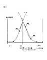
AF回路11は、積算回路10による積算値を用いて焦点評価値を得る。図2は、撮影レンズ1内の不図示のフォーカスレンズの位置と焦点評価値との関係の一例を示す図である。図2において、横軸はフォーカスレンズの位置であり、縦軸は焦点評価値である。焦点評価値を最大にするレンズ位置D1は、主要被写体に対するフォーカスレンズの合焦位置である。合焦位置は、カメラから主要被写体までの距離に応じて変化する。 The
焦点評価値の演算は、たとえば、フォーカスレンズを∞(無限遠)側から至近側へ向けて移動させながら行う。AF回路11が繰り返し焦点評価値を算出する場合の算出レートは、撮像素子2による撮像時間、フィルタ処理および積算値演算に要する時間によって決定される。したがって、図2において黒丸で示すように、焦点評価値は算出レートごとの離散データとしてプロットされる。AF回路11は、焦点評価値カーブの最大点を含むP1〜P3の3点について、いわゆる3点内挿演算を行って焦点評価値カーブの極大点に対応するレンズ位置D1を算出する。レンズ位置D1は、最大点P2と点P3とを通る傾きαの直線と、点P1を通る傾き−αの直線との交点に対応する。このレンズ位置D1は、撮像素子2によって撮像される被写体像のエッジのボケをなくし、画像のコントラストを最大にする位置である。 The calculation of the focus evaluation value is performed, for example, while moving the focus lens from the ∞ (infinity) side to the close side. The calculation rate in the case where the
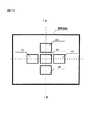
以上の焦点評価値算出処理は、撮影画面内に複数のフォーカスエリアを設け、各フォーカスエリアに対応してそれぞれ行う。図3は、AF電子カメラが横位置で構えられた場合の撮影画面内の5つのフォーカスエリアA1〜A5を例示する図である。本実施形態では、フォーカスエリアA1〜A5のそれぞれに対応させて焦点評価値算出を行うことにより、5つのフォーカスエリアA1〜A5に関する焦点評価値が個別に算出される。 The above-described focus evaluation value calculation processing is performed for each focus area by providing a plurality of focus areas in the shooting screen. FIG. 3 is a diagram illustrating five focus areas A1 to A5 in the shooting screen when the AF electronic camera is held in a horizontal position. In the present embodiment, the focus evaluation values for the five focus areas A1 to A5 are individually calculated by calculating the focus evaluation values corresponding to the focus areas A1 to A5.
一般に、複数のフォーカスエリアを有する場合は、主として合焦させるべきフォーカスエリアを選択する必要がある。この選択には、撮影者が操作部材を操作して選択する方式や、CPU12が複数のフォーカスエリアの中から最至近、あるいは最遠の被写体に対応するフォーカスエリアを自動的に選択する方式などがある。 In general, when a plurality of focus areas are provided, it is necessary to mainly select a focus area to be focused. For this selection, a method in which the photographer operates and selects an operation member, a method in which the
本説明では、フォーカスエリアを自動的に選択する方式が設定されたAF電子カメラが、複数のフォーカスエリアから最至近の被写体に対応するフォーカスエリアを所定数(たとえば1つ)選ぶ動作を中心に説明する。 In this description, the AF electronic camera in which the method for automatically selecting the focus area is set will focus on the operation of selecting a predetermined number (for example, one) of focus areas corresponding to the closest subject from a plurality of focus areas. To do.
図3に例示したフォーカスエリアA1〜A5を示すマークは、たとえば、AF電子カメラの液晶表示モニタ(不図示)に表示されるモニタ用の撮影画像(スルー画像と呼ばれる)に重ねてオーバーレイ表示される。スルー画像は、撮影指示に応じて撮像素子2が行う撮像(本撮影)の前に、撮像素子2が所定時間ごとに繰り返し行う撮像(予備撮影)で得られる画像である。AF電子カメラは、選択したフォーカスエリアを示すマークを選択していないフォーカスエリアを示すマークと異なる態様で表示する。たとえば、選択したフォーカスエリアのマークの色を選択していないフォーカスエリアのマークの色と異ならせたり、表示マークの輝度を変えたりして表示する。 The marks indicating the focus areas A1 to A5 illustrated in FIG. 3 are displayed in an overlay manner, for example, overlaid on a monitor photographed image (called a through image) displayed on a liquid crystal display monitor (not shown) of the AF electronic camera. . The through image is an image obtained by imaging (preliminary shooting) that is repeatedly performed by the
(AF処理)
AF電子カメラのCPU12で行われるAF処理について、図4のフローチャートを参照して説明する。図4による処理は、たとえば、不図示のレリーズスイッチから半押し操作信号がCPU12に入力されると開始される。ステップ#1において、CPU12は、処理に必要なフラグ類を初期化してステップ#2へ進む。初期化により、画像データの低周波数成分まで透過するようにバンドパスフィルタ9のフィルタ係数F1が設定される。フィルタ係数F1は、高周波数成分が少ない白黒エッジチャートから焦点評価値の変化を検出することに適した係数である。(AF processing)
The AF process performed by the
ステップ#2において、CPU12はサーチ初期値(フォーカスレンズの移動範囲)を設定する。本実施形態では、サーチ開始位置SSLPを至近端位置に、サーチ終了位置SELPを無限遠(∞)側の位置に、それぞれ設定する。なお、サーチ開始位置を無限遠端に、サーチ終了位置を至近端に設定してもよい。 In
CPU12はさらに、レンズ移動速度LMVの値をLMV1に設定してステップ#3へ進む。サーチ開始位置SSLPからサーチ終了位置SELPまでのフォーカスレンズの移動時間は、この移動速度LMVによって決定される。レンズ移動速度LMVを遅くすると図2におけるプロット数が多くなり、レンズ移動速度LMVを速くするとプロット数が少なくなる。レンズ移動速度LMVは、焦点評価値カーブの「山」を構成するプロット数が少なくとも3点以上になるように設定するのが好ましい。 The
ステップ#3において、CPU12はモータ13へ駆動信号を出力し、フォーカスレンズ(不図示)をサーチ開始位置SSLPへ移動させてステップ#4へ進む。図5は、AF処理の経過時間(横軸)およびフォーカスレンズ位置(縦軸)の関係を示す図である。図5において、タイミングt1からモータ13が駆動開始され、タイミングt2においてフォーカスレンズがサーチ開始位置SSLP(ここでは至近端)に到達する。 In
ステップ#4において、CPU12は、積算回路10による積算値(焦点評価値)を取得し、フォーカスレンズの位置を示す情報に関連づけて履歴データとしてAF回路11内にそれぞれ記憶し、ステップ#5へ進む。履歴データは、フォーカスエリアごとに記憶する。フォーカスレンズの位置は、たとえば、フォーカス制御機構14からレンズ位置を示す情報を入力して取得する。 In
ステップ#5において、CPU12は、モータ13へ駆動信号を出力してステップ#6へ進む。これにより、フォーカスレンズが上記レンズ移動速度LMV1で駆動される。ステップ#6において、CPU12は、フォーカスレンズの位置がサーチ終了位置SELPか否かを判定する。CPU12は、フォーカスレンズ位置がサーチ終了位置SELPの場合にステップ#6を肯定判定してステップ#7へ進む。一方、フォーカスレンズ位置がサーチ終了位置SELPに到達していない場合には、ステップ#6を否定判定してステップ#4へ戻る。 In
以上のステップ#4〜ステップ#6の処理により、フォーカスレンズの位置がサーチ開始位置SSLPからサーチ終了位置SELPまで移動する間(図5のタイミングt3〜タイミングt4)に、焦点評価値カーブを表す複数の焦点評価値が得られる。ここでは、焦点評価値カーブを構成する複数の焦点評価値を、焦点評価値履歴と呼ぶ。 As a result of the processes of
ステップ#7において、CPU12は、各フォーカスエリアごとに焦点評価値履歴を用いてエリア合焦位置を計算する。合焦位置の計算は、図2のように最大値およびその両隣りの3点について、3点内挿演算を行って焦点評価値履歴カーブの極大値に対応するレンズ位置を算出する。焦点評価値履歴から算出される極大値をMax[x]とし、極大値Max[x]に対応するレンズ位置をエリア合焦位置InfocusPosA[x]とする。CPU12は、エリア合焦位置InfocusPosA[x]を算出するとステップ#8へ進む。xには、5つのフォーカスエリアA1〜A5のそれぞれに対応して、1〜5のいずれかの値が代入される。 In
なお、焦点評価値履歴に所定レベル以上の焦点評価値が含まれていない場合は、当該フォーカスエリアをローコントラストエリアと判定して他のフォーカスエリアと識別できるようにする。ローコントラストエリアは、被写体が白壁や黒壁などのためコントラストが低く、焦点検出処理に必要なコントラスト情報が得られない場合に判定される。ローコントラストエリアでは、焦点評価値の最大点がノイズなどによって生じるため、擬合焦のおそれがある。 When the focus evaluation value history does not include a focus evaluation value of a predetermined level or higher, the focus area is determined as a low contrast area so that it can be distinguished from other focus areas. The low contrast area is determined when contrast is low because the subject is a white wall or a black wall, and contrast information necessary for focus detection processing cannot be obtained. In the low contrast area, the maximum point of the focus evaluation value is generated by noise or the like, and there is a risk of pseudo-focusing.
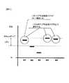
ステップ#8において、CPU12は、ローコントラストエリアを除く各フォーカスエリアにおけるエリア合焦位置InfocusPosA[x]の中から最至近の被写体に対応するものを計算し、最終合焦位置InfocusPosFとする。最終合焦位置InfocusPosFに対応するフォーカスエリアを最終合焦位置エリアInfocusAreaFとする。図6は、フォーカスエリアとエリア合焦位置との関係の一例を示す図である。図6において、横軸はエリア番号であり、縦軸は各フォーカスエリアのエリア合焦位置である。図6によれば、最至近のエリア合焦位置(最終合焦位置InfocusPosF)は、フォーカスエリアA4によって得られる。エリア合焦位置InfocusPosA[x]はカメラから被写体までの距離に応じて異なる値を有するため、距離情報といえる。したがって、エリア合焦位置InfocusPosA[x]を求めることは、カメラから被写体までの距離測定に対応する。 In
ステップ#9において、CPU12は、最終合焦位置InfocusPosFおよび最終合焦位置InfocusPosFから所定範囲内にエリア合焦位置InfocusPosA[x]を有するフォーカスエリアの全てを合焦エリアとして選び、ステップ#10へ進む。図6によれば、最終合焦位置InfocusPosFから所定範囲ΔPos内にエリア合焦位置InfocusPosA[x]を有するフォーカスエリアは、フォーカスエリアA4、A5およびA1である。所定範囲ΔPosは、たとえば、焦点深度の0.5倍〜1.0倍のいずれかの値に設定する。この場合の焦点深度は、あらかじめ定めた値を用いてもよいし、撮影時のF値および焦点距離等の情報に基づいて算出される値を用いてもよい。なお、上記選択される合焦エリアでは、測距によって得られる被写体までの距離は、合焦している被写体までの距離から所定距離内(被写界深度内)である。 In
ステップ#10において、CPU12は、ステップ#9で選択した合焦エリアから1つの合焦エリアを選択するための合焦表示エリア選択優先度を決定してステップ#11へ進む。図7は、決定された合焦表示エリア選択優先度の一例を示す図である。図7によれば、フォーカスエリアA1〜A5の順に、選択優先度1〜5が決定される。 In
ステップ#11において、CPU12は、ステップ#10で決定した選択優先度に基づいて、ステップ#9で選択した合焦エリアから1つの合焦エリア(合焦表示エリアと呼ぶことにする)を選んでステップ#12へ進む。図6の例では、合焦エリアA4、A5およびA1の中から、最も選択優先度が高い合焦エリアA1が選択される。なお、上述したステップ#8において最至近に該当するものが複数存在する場合は、ステップ#10で決定される選択優先度に基づいて最終合焦位置InfocusPosFを決定する。 In
ステップ#12において、CPU12はモータ13へ駆動信号を出力し、フォーカスレンズ(不図示)をサーチ終了位置SELPからステップ#8で算出した最至近のエリア合焦位置(最終合焦位置InfocusPosF)へ移動させて図4による処理を終了する。図5において、タイミングt5からモータ13が駆動開始され、タイミングt6においてフォーカスレンズが最終合焦位置InfocusPosFに到達する。CPU12はさらに、フォーカスレンズの駆動が完了した時点において、液晶表示モニタ(不図示)にオーバーレイ表示しているフォーカスエリアA1〜A5を示すマークのうち、合焦表示エリアを示すマークを他のフォーカスエリアを示すマークと異なる態様で表示させる。 In
なお、全てのフォーカスエリアがローコントラストエリアと判定されている場合のCPU12は、ステップ#12において、フォーカスレンズ(不図示)をサーチ終了位置SELPから検出不能時の所定のレンズ位置(撮影距離1m〜3mのいずれかに対応する位置)に移動させて図4による処理を終了する。 When all the focus areas are determined to be low contrast areas, the
以上説明した実施形態によれば、以下の作用効果が得られる。
(1)AF電子カメラは、複数のフォーカスエリアのそれぞれについて算出したエリア合焦位置InfocusPosA[x]の中から最至近の被写体に対応するものを最終合焦位置InfocusPosFとし、この位置へフォーカスレンズを移動させるようにした。最至近に該当するものが複数存在する場合は、合焦表示エリア選択優先度に基づいて最終合焦位置InfocusPosFを決定する。したがって、異なるフォーカスエリアに存在する被写体がAF電子カメラから等距離にあっても、必ず所定数(上記例では1つ)のフォーカスエリア(合焦エリア)を選択できる。According to the embodiment described above, the following effects can be obtained.
(1) The AF electronic camera uses the area focus position InfocusPosA [x] calculated for each of the plurality of focus areas as the final focus position InfocusPosF corresponding to the closest subject, and the focus lens is moved to this position. I moved it. When there are a plurality of objects corresponding to the closest distance, the final focus position InfocusPosF is determined based on the focus display area selection priority. Therefore, even if subjects existing in different focus areas are equidistant from the AF electronic camera, a predetermined number (in the above example, one) of focus areas (in-focus areas) can always be selected.
(2)合焦表示エリア選択優先度は、AF電子カメラが横位置姿勢の場合に撮影画面の中央、左、右、上(天)、下(地)の順に、選択優先度を1、2、3、4、5とした。一般に、主要被写体が存在する可能性は、撮影者の意図に応じて画面中央、左、右、上(天)、下(地)の順に下がると考えられる。そこで、この順番でフォーカスエリアの選択優先度を決定することにより、主要被写体と他の被写体とが異なるフォーカスエリアにそれぞれ存在し、両被写体がカメラから等距離に位置する場合、カメラが選択する合焦表示エリアが撮影者の意志と合致する可能性を高めることができる。(2) When the AF electronic camera is in the horizontal position and orientation, the selection display priority is set to 1, 2 in the order of the center, left, right, top (top), bottom (ground) of the shooting screen. 3, 4, and 5. In general, the possibility that a main subject exists is considered to decrease in the order of the center of the screen, left, right, upper (top), and lower (ground) according to the photographer's intention. Therefore, by determining the selection priority of the focus area in this order, when the main subject and the other subject exist in different focus areas, and both subjects are located at the same distance from the camera, the camera selects The possibility that the focus display area matches the will of the photographer can be increased.
(3)AF電子カメラは、最終合焦位置InfocusPosFおよび最終合焦位置InfocusPosFから所定範囲ΔPos内にエリア合焦位置InfocusPosA[x]を有するフォーカスエリアのうち、最も選択優先度が高いエリアを合焦表示エリアとして選択するようにした。これにより、2以上のフォーカスエリアにそれぞれ存在する被写体がカメラから等距離に位置する場合、各被写体が静止しているにもかかわらず、焦点評価値の検出誤差に起因して図4の処理を行う度に異なる合焦エリアを選択することが防止され、選択優先度に基づいて同じ合焦エリアを選択できる。この結果、選択した合焦エリアを示すマークを他のフォーカスエリアを示すマークと異なる態様で表示させる場合、被写体が移動しない限り表示状態(異なる態様で表示するマークの数や位置)が変化しないので、表示状態が変化する場合に比べて煩わしさを低減できる。(3) The AF electronic camera focuses on the area with the highest selection priority among the focus area having the area focus position InfocusPosA [x] within the predetermined range ΔPos from the final focus position InfocusPosF and the final focus position InfocusPosF. Now selected as the display area. Accordingly, when subjects existing in two or more focus areas are located at the same distance from the camera, the processing of FIG. 4 is performed due to the detection error of the focus evaluation value even though each subject is stationary. It is possible to prevent different focus areas from being selected each time they are performed, and the same focus area can be selected based on the selection priority. As a result, when the mark indicating the selected focus area is displayed in a different form from the marks indicating the other focus areas, the display state (the number and position of the marks displayed in different forms) does not change unless the subject moves. The troublesomeness can be reduced compared to the case where the display state changes.
(変形例1)
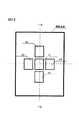
ステップ#10において決定した合焦表示エリア選択優先度を、姿勢検出回路15から出力される検出信号に応じて変更してもよい。図8は、AF電子カメラが縦位置で構えられた場合の撮影画面内の5つのフォーカスエリアA1〜A5を例示する図である。この場合のCPU12は、たとえば、撮影画面の中央、上(天)、左、右、下(地)の順に主要被写体が存在する可能性が下がると判定し、この順番でフォーカスエリアの選択優先度を変更する。図9は、縦位置撮影時に変更された合焦表示エリア選択優先度の一例を示す図である。図9によれば、フォーカスエリアA1〜A5の順に選択優先度1、2、5、4、3が決定される。なお、縦位置姿勢で変更した選択優先度は、横位置姿勢を検出した場合に横位置用の選択優先度に再度変更する。(Modification 1)
The focus display area selection priority determined in
(変形例2)
また、ステップ#10において決定した合焦表示エリア選択優先度を、設定されている撮影モードに応じて変更してもよい。CPU12は、たとえば、縦位置で構えられたAF電子カメラの撮影モードがポートレートモードに設定された場合、撮影画面の上(天)、中央、左、右、下(地)の順に主要被写体が存在する可能性が下がると判定し、この順番でフォーカスエリアの選択優先度を変更する。図10は、縦位置のポートレート撮影モード時に変更された合焦表示エリア選択優先度の一例を示す図である。図10によれば、フォーカスエリアA1〜A5の順に選択優先度2、1、5、4、3が決定される。実際のポートレート撮影において、被写体人物の顔が選択優先度1位の画面上(フォーカスエリアA2)に存在せず、選択優先度2位の画面中央(フォーカスエリアA1)に存在する場合、画面上(フォーカスエリアA2)は背景になるので、選択優先度2位の画面中央(フォーカスエリアA1)が最終合焦位置エリアInfocusAreaFとされる。(Modification 2)
Further, the focus display area selection priority determined in
(変形例3)
上述したAF電子カメラは、複数のフォーカスエリアのそれぞれについて算出したエリア合焦位置InfocusPosA[x]の中から最至近の被写体に対応するレンズ位置情報を最終合焦位置InfocusPosFとし、この位置へフォーカスレンズを移動させるようにした。この代わりに、複数のフォーカスエリアのそれぞれについて算出したエリア合焦位置InfocusPosA[x]の中から最遠の被写体に対応するレンズ位置情報を最終合焦位置InfocusPosFとし、この位置へフォーカスレンズを移動させるようにしてもよい。最遠に該当するものが複数存在する場合は、合焦表示エリア選択優先度に基づいて最終合焦位置InfocusPosFを決定すればよい。最至近の被写体に対応するレンズ位置情報を最終合焦位置InfocusPosFにするか、最遠の被写体に対応するレンズ位置情報を最終合焦位置InfocusPosFにするかの選択方式(至近優先/最遠優先などの選択方式)は、あらかじめAF電子カメラに設定されている。(Modification 3)
In the AF electronic camera described above, the lens position information corresponding to the closest subject from the area focus position InfocusPosA [x] calculated for each of the plurality of focus areas is set as the final focus position InfocusPosF, and the focus lens is moved to this position. Was moved. Instead, the lens position information corresponding to the farthest subject from the area focus position InfocusPosA [x] calculated for each of the plurality of focus areas is set as the final focus position InfocusPosF, and the focus lens is moved to this position. You may do it. If there are a plurality of objects corresponding to the farthest distance, the final focus position InfocusPosF may be determined based on the focus display area selection priority. Selection method for selecting whether the lens position information corresponding to the closest subject is the final focus position InfocusPosF or the lens position information corresponding to the farthest subject is the final focus position InfocusPosF (closest priority / farthest priority, etc.) Is selected in advance in the AF electronic camera.
(変形例4)
上述した最至近や最遠の被写体に対応するレンズ位置情報を選択する他に、公知の顔検出技術や、所定色検出、および特定の輪郭検出技術によって検出された被写体像の領域に対応するレンズ位置情報を選択するように構成してもよい。この場合のCPU12は、検出した被写体領域(たとえば人の顔)に対応するエリア合焦位置を最終合焦位置InfocusPosFとし、この位置へフォーカスレンズを移動させる。そして、最終合焦位置InfocusPosFおよび最終合焦位置InfocusPosFから所定範囲ΔPos内にエリア合焦位置InfocusPosA[x]を有するフォーカスエリアのうち、最も選択優先度が高いエリアを合焦表示エリアとして選択する。(Modification 4)
In addition to selecting the lens position information corresponding to the closest or farthest subject described above, the lens corresponding to the region of the subject image detected by the known face detection technique, the predetermined color detection, and the specific contour detection technique You may comprise so that position information may be selected. In this case, the
(変形例5)
ステップ#10において決定した合焦表示エリア選択優先度は、過去に最終合焦位置InfocusPosFとされた頻度に応じて異ならせてもよい。CPU12は、最終合焦位置InfocusPosFとした回数が多いフォーカスエリアの選択優先度を高くし、最終合焦位置InfocusPosFとした回数が少ないフォーカスエリアの選択優先度を低くする。これにより、撮影者が撮影画面の特定の領域に主要被写体を位置させる構図を好む場合、カメラが選択する合焦表示エリアが撮影者の意志と合致する可能性を高めることができる。たとえば、直近の50回の撮影における最終合焦位置InfocusPosFの履歴情報を保存する構成にすることにより、過去の撮影時の最終合焦位置InfocusPosFの頻度を合焦表示エリアの選択優先度に反映させることができる。なお、直近の50回の撮影における最終合焦位置InfocusPosFの履歴情報には、AF電子カメラ自動的に決定したフォーカスエリアの履歴や、撮影者によってマニュアル設定されたフォーカスエリアの履歴を含めるようにしてもよい。(Modification 5)
The focus display area selection priority determined in
(変形例6)
ステップ#10において決定した合焦表示エリア選択優先度を、流し撮り撮影時に変更してもよい。CPU12は、たとえば、姿勢検出回路15からの検出信号によってAF電子カメラが流し撮り撮影すると判定した場合、進行方向と逆に位置するフォーカスエリアの選択優先度を上げる。一般に、移動する被写体を撮影する場合、撮影画面において移動被写体の前方(進行方向側)に空間を確保することが多い。この場合の移動被写体は、撮影画面において進行方向と反対側に位置することが多くなる。このような場合、撮影画面において流し撮り方向と逆側に位置するフォーカスエリアの選択優先度を高めることにより、カメラが選択する合焦表示エリアが撮影者の意志と合致する可能性を高めることができる。(Modification 6)
The focus display area selection priority determined in
以上の説明では、撮影画面の複数のフォーカスエリアのそれぞれで山登り方式によるAF動作を行う例を説明した。AF動作は、2以上のフォーカスエリアを用いて行うものであれば、周知の瞳分割によって位相差を検出する方式のAF動作を行うように構成してもよい。この場合にも、各フォーカスエリアに存在する被写体までの距離情報が得られるので、最終合焦位置InfocusPosFから所定範囲ΔPos内にエリア合焦位置InfocusPosA[x]を有するフォーカスエリアのうち、最も選択優先度が高いフォーカスエリアを選択するように構成すればよい。 In the above description, the example in which the AF operation by the hill climbing method is performed in each of the plurality of focus areas on the shooting screen has been described. As long as the AF operation is performed using two or more focus areas, the AF operation may be configured to detect a phase difference by a known pupil division. Also in this case, since distance information to the subject existing in each focus area is obtained, the most selective priority is selected from the focus areas having the area focus position InfocusPosA [x] within the predetermined range ΔPos from the final focus position InfocusPosF. What is necessary is just to comprise so that a focus area with high degree may be selected.
電子カメラを例に説明したが、銀塩カメラの焦点検出装置に本発明を適用してもよい。 Although an electronic camera has been described as an example, the present invention may be applied to a focus detection device for a silver salt camera.
以上の説明はあくまで一例であり、発明を解釈する上で、上記の実施形態の構成要素と本発明の構成要素との対応関係に何ら限定されるものではない。 The above description is merely an example, and the interpretation of the invention is not limited to the correspondence between the components of the above-described embodiment and the components of the present invention.
1…レンズユニット
2…撮像素子
3…A/D変換器
4…メモリ
5…画像処理回路
7…AE/AWB回路
8…コントロール回路
9…バンドパスフィルタ
10…積算回路
11…AF回路
12…CPU
13…モータ
14…フォーカス制御機構
15…姿勢検出回路DESCRIPTION OF
13 ...
Claims (8)
Translated fromJapanese前記測距手段によって検出された距離情報に基づいて合焦レンズ位置を演算するレンズ位置演算手段と、
前記2以上のフォーカス検出用領域の中から、前記合焦レンズ位置に対応する領域を所定の優先順位に基づいて選択する領域選択手段と、
前記領域選択手段によって選択された領域(以下、選択領域)を表示する表示手段とを備えることを特徴とするオートフォーカスカメラ。Distance measuring means for detecting distance information to a subject included in each of two or more different focus detection areas in a shooting screen;
Lens position calculation means for calculating a focus lens position based on distance information detected by the distance measurement means;
A region selecting means for selecting a region corresponding to the focusing lens position from the two or more focus detection regions based on a predetermined priority;
An autofocus camera comprising: display means for displaying an area selected by the area selection means (hereinafter referred to as a selection area).
前記レンズ位置演算手段は、前記測距手段で検出された複数の距離情報のうち、前記2以上のフォーカス検出用領域からあらかじめ設定されている選択方式で選択したフォーカス検出用領域に対応する距離情報に基づくレンズ位置を前記合焦レンズ位置とし、
前記領域選択手段は、前記合焦レンズ位置を含む所定深度内のレンズ位置に対応するフォーカス検出用領域から前記選択領域を選択することを特徴とするオートフォーカスカメラ。The autofocus camera according to claim 1,
The lens position calculation means includes distance information corresponding to a focus detection area selected by a selection method preset from the two or more focus detection areas among a plurality of distance information detected by the distance measurement means. The lens position based on the focus lens position,
The auto-focus camera, wherein the area selection unit selects the selection area from a focus detection area corresponding to a lens position within a predetermined depth including the focus lens position.
カメラの縦位置姿勢および横位置姿勢を検出する姿勢検出手段をさらに備え、
前記領域選択手段は、前記姿勢検出手段により検出された姿勢に応じて前記フォーカス検出用領域の優先順位を変更することを特徴とするオートフォーカスカメラ。The autofocus camera according to claim 1 or 2,
It further comprises posture detection means for detecting the vertical position and horizontal position of the camera,
The autofocus camera according to claim 1, wherein the area selection unit changes the priority order of the focus detection areas in accordance with the attitude detected by the attitude detection unit.
前記領域選択手段は、前記姿勢検出手段によってカメラが縦位置であることが検出された場合、撮影画面において左右側より天位置側のフォーカス検出用領域の優先順位を上にすることを特徴とするオートフォーカスカメラ。In the autofocus camera according to claim 3,
The area selection means sets the priority of the focus detection area on the top position side higher than the left and right sides on the shooting screen when the posture detection means detects that the camera is in the vertical position. Autofocus camera.
前記領域選択手段は、前記姿勢検出手段によってカメラが横位置であることが検出された場合、撮影画面において天位置側より左右側のフォーカス検出用領域の優先順位を上にすることを特徴とするオートフォーカスカメラ。In the autofocus camera according to claim 3,
The area selection means sets the priority order of the focus detection areas on the left and right sides higher than the top position side on the shooting screen when the posture detection means detects that the camera is in the horizontal position. Autofocus camera.
前記領域選択手段は、設定されている撮影シーンモードに応じて前記フォーカス検出用領域の優先順位を変更することを特徴とするオートフォーカスカメラ。The autofocus camera according to claim 1 or 2,
The auto-focus camera according to claim 1, wherein the area selection unit changes the priority order of the focus detection areas in accordance with a set shooting scene mode.
前記領域選択手段は、カメラがポートレート撮影モードに設定された場合、撮影画面において中央より天位置側のフォーカス検出用領域の優先順位を上にすることを特徴とするオートフォーカスカメラ。In the autofocus camera according to claim 6,
The auto-focus camera according to claim 1, wherein when the camera is set to a portrait shooting mode, the area selection unit sets the priority order of the focus detection area on the top position side from the center on the shooting screen.
前記領域選択手段は、前記レンズ位置演算手段によって前記合焦レンズ位置として演算される頻度に応じて、対応する前記フォーカス検出用領域の優先順位を変更することを特徴とするオートフォーカスカメラ。The autofocus camera according to claim 1 or 2,
The auto-focus camera according to claim 1, wherein the area selection unit changes the priority order of the corresponding focus detection areas according to the frequency calculated as the focus lens position by the lens position calculation unit.
Priority Applications (1)
| Application Number | Priority Date | Filing Date | Title |
|---|---|---|---|
| JP2005328505AJP2007133301A (en) | 2005-11-14 | 2005-11-14 | Auto focus camera |
Applications Claiming Priority (1)
| Application Number | Priority Date | Filing Date | Title |
|---|---|---|---|
| JP2005328505AJP2007133301A (en) | 2005-11-14 | 2005-11-14 | Auto focus camera |
Publications (1)
| Publication Number | Publication Date |
|---|---|
| JP2007133301Atrue JP2007133301A (en) | 2007-05-31 |
Family
ID=38154998
Family Applications (1)
| Application Number | Title | Priority Date | Filing Date |
|---|---|---|---|
| JP2005328505APendingJP2007133301A (en) | 2005-11-14 | 2005-11-14 | Auto focus camera |
Country Status (1)
| Country | Link |
|---|---|
| JP (1) | JP2007133301A (en) |
Cited By (7)
| Publication number | Priority date | Publication date | Assignee | Title |
|---|---|---|---|---|
| JP2011015304A (en)* | 2009-07-03 | 2011-01-20 | Sanyo Electric Co Ltd | Electronic camera |
| JP2012514886A (en)* | 2009-01-02 | 2012-06-28 | サムスン エレクトロニクス カンパニー リミテッド | Video data acquisition method and apparatus |
| US8254775B2 (en) | 2010-01-06 | 2012-08-28 | Renesas Electronics Corporation | Autofocus control method |
| JP2013195611A (en)* | 2012-03-19 | 2013-09-30 | Ricoh Co Ltd | Imaging apparatus and display processing method |
| JP2014016534A (en)* | 2012-07-10 | 2014-01-30 | Olympus Imaging Corp | Imaging device and focus adjustment method of imaging device |
| JP2016061798A (en)* | 2014-09-12 | 2016-04-25 | キヤノン株式会社 | Automatic focusing apparatus and automatic focusing method |
| CN111226153A (en)* | 2018-08-02 | 2020-06-02 | 深圳市大疆创新科技有限公司 | Control device, method, and program |
- 2005
- 2005-11-14JPJP2005328505Apatent/JP2007133301A/enactivePending
Cited By (7)
| Publication number | Priority date | Publication date | Assignee | Title |
|---|---|---|---|---|
| JP2012514886A (en)* | 2009-01-02 | 2012-06-28 | サムスン エレクトロニクス カンパニー リミテッド | Video data acquisition method and apparatus |
| JP2011015304A (en)* | 2009-07-03 | 2011-01-20 | Sanyo Electric Co Ltd | Electronic camera |
| US8254775B2 (en) | 2010-01-06 | 2012-08-28 | Renesas Electronics Corporation | Autofocus control method |
| JP2013195611A (en)* | 2012-03-19 | 2013-09-30 | Ricoh Co Ltd | Imaging apparatus and display processing method |
| JP2014016534A (en)* | 2012-07-10 | 2014-01-30 | Olympus Imaging Corp | Imaging device and focus adjustment method of imaging device |
| JP2016061798A (en)* | 2014-09-12 | 2016-04-25 | キヤノン株式会社 | Automatic focusing apparatus and automatic focusing method |
| CN111226153A (en)* | 2018-08-02 | 2020-06-02 | 深圳市大疆创新科技有限公司 | Control device, method, and program |
Similar Documents
| Publication | Publication Date | Title |
|---|---|---|
| JP4674471B2 (en) | Digital camera | |
| JP5394296B2 (en) | Imaging apparatus and image processing method | |
| JP5167750B2 (en) | TRACKING DEVICE, IMAGING DEVICE, AND TRACKING METHOD | |
| JP5247076B2 (en) | Image tracking device, focus adjustment device, and imaging device | |
| JP4998308B2 (en) | Focus adjustment device and imaging device | |
| US20080181460A1 (en) | Imaging apparatus and imaging method | |
| JP5380784B2 (en) | Autofocus device, imaging device, and autofocus method | |
| JP2009133903A (en) | Imaging apparatus and imaging method thereof | |
| JP2008009341A (en) | Autofocus device and method, and imaging apparatus | |
| US20060002698A1 (en) | Image-taking apparatus and focusing method | |
| JP2009115981A (en) | Photographing device, its control method, and program | |
| JP2008009340A (en) | Autofocus device and method, and imaging apparatus | |
| US11582394B2 (en) | Control apparatus, control method, and storage medium for providing tilt control | |
| JP4893334B2 (en) | Image tracking device and imaging device | |
| JP2014013368A (en) | Imaging apparatus and control method thereof | |
| JP2004361484A (en) | Auto focus camera | |
| JP2003307669A (en) | camera | |
| JP2011097645A (en) | Image synthesizing apparatus, imaging apparatus, and image synthesizing method | |
| JP2005003813A (en) | Imaging apparatus, imaging system, and imaging method | |
| JP2015106116A (en) | Imaging device | |
| JP4645413B2 (en) | Imaging device | |
| JP2014106324A (en) | Autofocus device and imaging device | |
| JP2005189634A (en) | Camera focus detection device | |
| JP2007133301A (en) | Auto focus camera | |
| JP4902946B2 (en) | Auto focus camera |