JP2007130132A - Endoscope insertion part shape grasping system - Google Patents
Endoscope insertion part shape grasping systemDownload PDFInfo
- Publication number
- JP2007130132A JP2007130132AJP2005324531AJP2005324531AJP2007130132AJP 2007130132 AJP2007130132 AJP 2007130132AJP 2005324531 AJP2005324531 AJP 2005324531AJP 2005324531 AJP2005324531 AJP 2005324531AJP 2007130132 AJP2007130132 AJP 2007130132A
- Authority
- JP
- Japan
- Prior art keywords
- shape
- insertion portion
- grasping system
- sensor
- endoscope insertion
- Prior art date
- Legal status (The legal status is an assumption and is not a legal conclusion. Google has not performed a legal analysis and makes no representation as to the accuracy of the status listed.)
- Withdrawn
Links
Images


Classifications
- A—HUMAN NECESSITIES
- A61—MEDICAL OR VETERINARY SCIENCE; HYGIENE
- A61B—DIAGNOSIS; SURGERY; IDENTIFICATION
- A61B1/00—Instruments for performing medical examinations of the interior of cavities or tubes of the body by visual or photographical inspection, e.g. endoscopes; Illuminating arrangements therefor
- A61B1/005—Flexible endoscopes
- A61B1/009—Flexible endoscopes with bending or curvature detection of the insertion part
Landscapes
- Health & Medical Sciences (AREA)
- Life Sciences & Earth Sciences (AREA)
- Surgery (AREA)
- Biomedical Technology (AREA)
- Medical Informatics (AREA)
- Optics & Photonics (AREA)
- Pathology (AREA)
- Radiology & Medical Imaging (AREA)
- Biophysics (AREA)
- Engineering & Computer Science (AREA)
- Physics & Mathematics (AREA)
- Heart & Thoracic Surgery (AREA)
- Nuclear Medicine, Radiotherapy & Molecular Imaging (AREA)
- Molecular Biology (AREA)
- Animal Behavior & Ethology (AREA)
- General Health & Medical Sciences (AREA)
- Public Health (AREA)
- Veterinary Medicine (AREA)
- Instruments For Viewing The Inside Of Hollow Bodies (AREA)
- Endoscopes (AREA)
Abstract
Translated fromJapaneseDescription
Translated fromJapanese本発明は、挿入時の内視鏡挿入部の位置を検出するとともに、その形状を表示する装置に関する。 The present invention relates to an apparatus that detects the position of an endoscope insertion portion during insertion and displays the shape thereof.
術者にとって、体内に挿入された内視鏡挿入部の形状の把握することは有用である。特に体内への挿入が困難な下部内視鏡の使用において、内視鏡挿入部の形状の把握は極めて有用である。これらのことから内視鏡挿入部の形状把握システムとして様々なものが提案されている。 It is useful for the surgeon to grasp the shape of the endoscope insertion portion inserted into the body. In particular, in the use of a lower endoscope that is difficult to insert into the body, grasping the shape of the endoscope insertion portion is extremely useful. From these facts, various systems for grasping the shape of the endoscope insertion portion have been proposed.
内視鏡挿入部の形状を表示するシステムとして、交流磁界を用いるものが知られている。これは、挿入部内の長手方向に沿って多数のコイルを所定間隔で配置し、交流磁界とコイルとの間の電磁相互作用を利用して各コイルの3次元空間内の位置および方位を検出するものである。内視鏡挿入部の形状は、コイルが配置された測定点の位置データに3次元スプライン曲線等を適用して再現され、モニタに表示される。 A system using an alternating magnetic field is known as a system for displaying the shape of the endoscope insertion portion. In this method, a large number of coils are arranged at predetermined intervals along the longitudinal direction in the insertion portion, and the position and orientation of each coil in the three-dimensional space are detected using the electromagnetic interaction between the AC magnetic field and the coil. Is. The shape of the endoscope insertion portion is reproduced by applying a three-dimensional spline curve or the like to the position data of the measurement point where the coil is arranged, and displayed on the monitor.
内視鏡挿入部は、一般に先端部に接続された湾曲部と、操作部と湾曲部との間を結ぶ軟性部に分けられる。湾曲部は、操作部に設けられたノブの操作に連動して湾曲される部分である。これに対し、軟性部は自由に撓曲する部分である。湾曲部がノブ操作により曲げられるとき、その曲率は、軟性部の自然な撓みによる曲率に比べ極めて大きく、湾曲の態様も大きく異なる。したがって、湾曲部の形状を、軟性部の形状再現と同じ方法で精度よく再現することはできない。 The endoscope insertion portion is generally divided into a bending portion connected to the distal end portion and a flexible portion connecting the operation portion and the bending portion. The bending portion is a portion that is bent in conjunction with operation of a knob provided in the operation portion. On the other hand, the soft part is a part that bends freely. When the bending portion is bent by the knob operation, the curvature is extremely larger than the curvature due to the natural bending of the soft portion, and the bending mode is also greatly different. Therefore, the shape of the curved portion cannot be accurately reproduced by the same method as the shape reproduction of the soft portion.
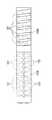
例えば図17に模式的に示されるように、軟性部120Aは螺旋管123から構成され、湾曲部120Bは多数の湾曲駒121から構成される。湾曲駒121は、それぞれヒンジ部122により隣接するもの同士が連結され、湾曲可能な構造とされている。また、図18に湾曲部120Bの別の構造を模式的に示す。図18の例では、湾曲部120Bは、2種類の湾曲駒121A、121Bから構成される。図18の構成では、湾曲部先端側に軟性部側の湾曲駒121Bよりも幅の狭い湾曲駒121Aが用いられ、湾曲部120Bの先端側は軟性部側よりも大きな曲率で湾曲できる。 For example, as schematically shown in FIG. 17, the
図17、18に示される構造から、湾曲部がノブ操作により曲げられるとき、その曲率は、軟性部の自然な撓みによる曲率に比べ極めて大きい。また、その湾曲の態様も大きく異なり、図19に示されるように同じ湾曲部120Bであっても複数の異なる曲率で湾曲される。したがって、湾曲部の形状を、軟性部の形状再現と同じ方法で精度よく再現することはできない。 From the structure shown in FIGS. 17 and 18, when the bending portion is bent by the knob operation, the curvature is extremely larger than the curvature due to the natural bending of the soft portion. Further, the manner of the curvature is also greatly different, and as shown in FIG. 19, even the same
上記問題に対しては、湾曲部に設置されるコイル数を増やすとともにその配置を密にし、これにより湾曲部の形状再現を正確にしたものが知られている(特許文献1)。
しかし、湾曲部への多数のコイルの設置は、湾曲部が許容できる曲率を制限し、コイルおよび湾曲部の耐久性をも低下させ、部品点数の増加、湾曲部寸法の増大等を招く。また、このような形状把握システムでは、X線を用いたときのように、周辺の臓器は表示されず内視鏡挿入部の形状のみが表示されるため実際の大きさを把握し難いと言う問題がある。 However, the installation of a large number of coils in the bending portion limits the curvature that the bending portion can tolerate, reduces the durability of the coil and the bending portion, and causes an increase in the number of parts, an increase in the size of the bending portion, and the like. Further, in such a shape grasping system, it is difficult to grasp the actual size because the surrounding organ is not displayed and only the shape of the endoscope insertion portion is displayed as in the case of using X-rays. There's a problem.
本発明は、簡略な構成で挿入部の形状を再現でき、挿入部の空間的な把握を容易にする内視鏡挿入部形状把握システムを提供することを目的としている。 An object of the present invention is to provide an endoscope insertion portion shape grasping system that can reproduce the shape of an insertion portion with a simple configuration and facilitates spatial grasp of the insertion portion.
本発明に関わる内視鏡挿入部形状把握システムは、可撓性を有する内視鏡挿入部の形状を把握するための内視鏡挿入部形状把握システムであって、挿入部の位置情報を所定間隔毎に検出する位置検出手段と、位置検出手段により検出された挿入部の位置情報から、挿入部の形状を再現する形状再現手段と、形状再現手段により求められた挿入部の再現形状を表示する画像表示手段とを備え、画像表示手段における画像表示において、再現形状に沿って、再現形状の大きさの把握を可能にするマークを表示することを特徴としている。 An endoscope insertion portion shape grasping system according to the present invention is an endoscope insertion portion shape grasping system for grasping the shape of a flexible endoscope insertion portion, and position information of the insertion portion is predetermined. Displays the position detection means that detects each interval, the shape reproduction means that reproduces the shape of the insertion portion from the position information of the insertion portion detected by the position detection means, and the reproduction shape of the insertion portion that is obtained by the shape reproduction means Image display means for displaying, in the image display by the image display means, a mark that enables the size of the reproduced shape to be grasped is displayed along the reproduced shape.
位置検出手段は、所定間隔毎に配置されるセンサを備え、マークは例えばセンサに対応する位置に表示される。またマークは、例えば挿入部に設けられた指標に対応する位置に表示されてもよい。 The position detecting means includes sensors arranged at predetermined intervals, and the mark is displayed at a position corresponding to the sensor, for example. Further, the mark may be displayed at a position corresponding to an index provided in the insertion portion, for example.
位置検出手段は、交流磁界を発生する磁場発生器と、交流磁界を検知する複数のコイルが所定間隔毎に配置された可撓性を有する管状部を備えるセンサプローブとからなる。センサプローブは内視鏡の所定のチャンネルに挿入され、位置検出手段は複数のコイルの位置を検知することにより位置情報を取得する。このとき管状部の長さは、挿入部の先端からチャンネルの入口までの長さに等しく、管状部の基端部は入口に嵌合される装着部に連結されることが好ましい。 The position detection means includes a magnetic field generator that generates an alternating magnetic field, and a sensor probe that includes a flexible tubular portion in which a plurality of coils that detect the alternating magnetic field are arranged at predetermined intervals. The sensor probe is inserted into a predetermined channel of the endoscope, and the position detection unit acquires position information by detecting the positions of the plurality of coils. At this time, the length of the tubular portion is equal to the length from the distal end of the insertion portion to the inlet of the channel, and the proximal end portion of the tubular portion is preferably connected to a mounting portion fitted to the inlet.
また、内視鏡挿入部形状把握システムは、挿入部における湾曲部の両端の間の距離を検出する距離検出手段と、この距離に対応して、湾曲部の形状を再現するための湾曲部形状データを格納するメモリとを備えることが好ましい。このとき距離検出手段は、位置検出手段により検出された両端の位置から上記距離を算出する距離算出手段とを備える。 Further, the endoscope insertion portion shape grasping system includes a distance detection means for detecting a distance between both ends of the bending portion in the insertion portion, and a bending portion shape for reproducing the shape of the bending portion corresponding to the distance. And a memory for storing data. At this time, the distance detection means includes distance calculation means for calculating the distance from the positions of both ends detected by the position detection means.
また位置検出手段は交流磁界を用い、交流磁界を発生する磁場発生器と、交流磁界を検知するセンサ部とを備え、センサ部からの信号に基づき湾曲部両端の位置を算出する。例えば湾曲部の両端において、挿入部の先端部側に第1コイル、挿入部の軟性部側に第2コイルとが配置される。センサ部のセンサは、第1及び第2コイルを含み、交流磁界により誘導される第1及び第2コイルの電気信号に基づき第1及び第2コイルの位置が算出される。 The position detection means includes an AC magnetic field, a magnetic field generator that generates an AC magnetic field, and a sensor unit that detects the AC magnetic field, and calculates positions of both ends of the bending portion based on a signal from the sensor unit. For example, at both ends of the bending portion, a first coil is disposed on the distal end side of the insertion portion, and a second coil is disposed on the flexible portion side of the insertion portion. The sensor of the sensor unit includes first and second coils, and the positions of the first and second coils are calculated based on the electrical signals of the first and second coils induced by the alternating magnetic field.
また、センサ部は可撓性を有する管状部を備えたセンサプローブからなり、センサプローブは、内視鏡の所定のチャンネルに挿入されることにより、第1及び第2コイルがこの両端に対応する位置に装置される。センサプローブは、位置算出手段に着脱自在であり、メモリは、センサプローブに設けられる。 Further, the sensor part is composed of a sensor probe having a flexible tubular part, and the sensor probe is inserted into a predetermined channel of the endoscope so that the first and second coils correspond to both ends. Device in position. The sensor probe is detachable from the position calculating means, and the memory is provided in the sensor probe.
更に、内視鏡挿入部形状把握システムは、湾曲部の形状を湾曲部形状データに基づいて再現する湾曲部形状再現手段を備え、湾曲部形状データは、湾曲部に関わる1点以上の位置情報からなる。また、内視鏡挿入部形状把握システムは、挿入部における軟性部の形状を再現する軟性部形状再現手段を備える。軟性部形状再現手段は、軟性部の長手方向に沿って配置される複数のセンサの位置を結ぶ補間曲線を用いて再現される。 Furthermore, the endoscope insertion portion shape grasping system includes a bending portion shape reproducing unit that reproduces the shape of the bending portion based on the bending portion shape data, and the bending portion shape data includes one or more pieces of position information related to the bending portion. Consists of. The endoscope insertion part shape grasping system includes a soft part shape reproducing unit that reproduces the shape of the soft part in the insertion part. The soft part shape reproducing means is reproduced by using an interpolation curve connecting the positions of a plurality of sensors arranged along the longitudinal direction of the soft part.
以上のように、本発明によれば、簡略な構成で挿入部の形状を再現でき、挿入部の空間的な把握を容易にする内視鏡挿入部形状把握システムを提供できる。 As described above, according to the present invention, it is possible to provide an endoscope insertion portion shape grasping system that can reproduce the shape of the insertion portion with a simple configuration and facilitates spatial grasp of the insertion portion.
以下、本発明の実施の形態を、図面を参照して説明する。
図1は、本発明の一実施形態である内視鏡挿入部形状把握システムが適用される内視鏡の概観図である。なお、本実施形態では、内視鏡の一例として電子内視鏡が採用されるがこれに限定されるものではない。Hereinafter, embodiments of the present invention will be described with reference to the drawings.
FIG. 1 is a schematic view of an endoscope to which an endoscope insertion portion shape grasping system according to an embodiment of the present invention is applied. In this embodiment, an electronic endoscope is employed as an example of an endoscope, but the present invention is not limited to this.
電子内視鏡10は、術者が把持・操作するための操作部11を備える。操作部11には、挿入部12及びライトガイドケーブル13がそれぞれ連結され、ライトガイドケーブル13の先端にはコネクタ13Aが設けられる。コネクタ13Aは、例えば光源と映像信号処理回路が一体的に収容されてなるプロセッサ装置(図示せず)に着脱自在に装着され、電子内視鏡10のコネクタ13A及びライトガイドケーブル13等を通してプロセッサ装置の光源部から照明光が体腔内に供給され、電子内視鏡10からの画像信号がプロセッサ装置の映像信号処理回路に供給される。 The
挿入部12は、軟性部12Aと、湾曲部12Bと、先端部12Cとから構成される。軟性部12Aは、自由に屈曲される可撓管であり、挿入部12の大部分を占め、操作部11に直接接続される。湾曲部12Bは、先端部12Cと軟性部12Aとの間を結ぶ区間に設けられ、操作部11に設けられたアングルノブ11Aの回転操作に連動して先端部12Cの向きが例えば約180°回転されるまで湾曲可能である。 The
挿入部12には、操作部11から先端部12Cまで連通する鉗子チャンネルが形成され、操作部11には、鉗子チャンネルの入り口となる鉗子口11Bが設けられる。なお、先端部12Cには、後述するように、撮像光学系や撮像素子、また照明光学系等が搭載される。 The
図2は、挿入部12の位置を検出・表示する挿入部形状把握システムにおいて用いられるセンサ部の構成を模式的に示す概略図である。また、図3は、センサ部の電気的な構成を模式的に示すブロック図である。 FIG. 2 is a schematic diagram schematically showing a configuration of a sensor unit used in an insertion unit shape grasping system that detects and displays the position of the
本実施形態において挿入部形状把握システムのセンサ部は、プローブ型のセンサ(センサプローブ)である。センサプローブ20は、可撓性を有する管状部21と、その一端に接続され鉗子口11Bに固定される装着部22とを備え、装着部22は、信号ケーブル23を介して位置検出装置本体25に着脱自在に装着されるコネクタ部24(図5参照)に連結される。 In this embodiment, the sensor part of the insertion part shape grasping system is a probe type sensor (sensor probe). The
管状部21の長さは、図1に示される内視鏡先端部12Cから、鉗子口11Bまでの長さLに等しく、その基端部は装着部22に接続される。装着部22において、管状部21の基端部が接続された位置には、管状部21を取り囲むように円筒形の嵌合部22Aが形成される。 The length of the
すなわち、管状部21の先端は、鉗子口11Bから鉗子チャンネル内に挿入され、その先端は先端部12Cにある鉗子チャンネルの先端に装置される。このとき管状部21の基端部は鉗子口11Bと略同位置となり、嵌合部22Aは、円筒形に突出する鉗子口11Bにピッタリと嵌め合わせられる。なお、装着部22が鉗子口11Bに装着された状態を図4に示す。 That is, the distal end of the
管状部21の先端には、第1センサS1が設けられる。第1センサS1から管の長手方向に沿って装着部22側へ距離B移動した位置には、第2センサS2が設けられる。第2センサS2よりも更に装着部22側には、所定の間隔A毎に第3センサS3、第4センサS4、第5センサS5、・・・、第nセンサSnが順次設けられる。第1センサS1〜第nセンサSnは、例えば磁気センサ用のコイルである。 A first sensor S <b> 1 is provided at the distal end of the
装着部22内には信号処理部22Bが設けられ、第1センサS1〜第nセンサSnの各々は、図3に示されるように、信号処理部22B内の多チャンネルA/D変換器221に電気的に接続される(図3にはS1〜S5のみ図示)。第1センサS1〜第nセンサSnからの信号は、各々多チャンネルプリアンプ220において所定のゲインで増幅された後、多チャンネルA/D変換器221においてA/D変換され、信号ケーブル23(図2)へと出力される。 A
また、装着部22の側面には、表示切替ボタン22C(後述)が設けられ、表示切替ボタン22Cは信号処理部22B内に設けられたスイッチ222に接続される。すなわち、表示切替ボタン22Cが操作されると、スイッチ222から画面切替信号が信号ケーブル23へと出力される。なお、A/D変換はコネクタ部24(図5)あるいは、位置検出装置本体25(図5)内で行なわれてもよい。 Further, a
図5は、本実施形態の挿入部形状把握システム全体のブロック図である。本実施形態では、挿入部形状把握システムは、例えばセンサプローブ、位置検出装置本体、磁場発生器、画像表示装置から構成される。 FIG. 5 is a block diagram of the entire insertion portion shape grasping system of the present embodiment. In the present embodiment, the insertion portion shape grasping system includes, for example, a sensor probe, a position detection device main body, a magnetic field generator, and an image display device.
図5において、センサプローブ20の管状部21は電子内視鏡10の鉗子チャンネルに装着されており、コネクタ部24は位置検出装置本体25に接続されている。上述したように、センサプローブ20は、鉗子口11Bから挿入部12内に設けられた鉗子チャンネル14に挿入され、その先端は、挿入部12の先端部12Cに配置される。すなわち、第1センサS1は、先端部12C内に配置される。 In FIG. 5, the
先端部12Cは、一般にリジッドな構成とされ、その内部には、撮像素子15やライトガイド16の先端16Aが配置される。また挿入部12の先端部12Cには、ライトガイド16からの光を照射するための照明用光学系16Bや撮像素子15に被写体像を結像するための撮像光学系15Aが設けられる。 The
一方、センサプローブ20のコネクタ部24は、位置検出装置本体25に着脱自在に接続される。センサプローブ20の各センサS1〜Snからの信号は、装着部22の信号処理部22B、信号ケーブル23、コネクタ部24を介して位置検出装置本体25の信号処理回路26に入力される。信号処理回路26では、第1センサS1〜第nセンサSnからの信号の増幅、検波、A/D変換が行われ、位置検出装置本体25の制御演算部27に入力される。なお、表示切替ボタン22C(図2、3、4)からの操作信号は、コネクタ部24から後述する画像表示制御部28へ直接入力される。 On the other hand, the
また、コネクタ部24には、不揮発性のメモリ24Mが設けられ、コネクタ部24が位置検出装置本体25に接続されると、メモリ24Mは制御演算部27に接続される。メモリ24Mには、後述するように、挿入部12の形状表示処理を行なう際に、湾曲部12Bの形状表示に用いられるデータ(湾曲部形状データ)が格納されている。湾曲部形状データは、例えば挿入部形状把握システムの電源が投入され、コネクタ部24が位置検出装置本体25に装着されると、メモリ24Mから制御演算部27へと出力される。 The
一方、位置検出装置本体25には、磁場発生器40が例えばコネクタを介して接続される。磁場発生器40は、例えば直交座標系XYZの各座標軸XYZに対応した方向に時系列的に交流磁場を発生する装置であり、その駆動は、位置検出装置本体25内の駆動回路XYZ29からの信号により駆動され、駆動回路XYZ29は、制御演算部27からの信号により制御される。 On the other hand, the
従来周知のように、交流磁界を用いた挿入部形状把握システムにおいて、センサプローブ20に設けられたコイルS1〜Snは、磁場発生器40から発生するこれら交流磁場からの電磁誘導作用により、磁場発生器40に設定されたXYZ座標系の座標軸方向(X、Y、Z軸方向)の距離に対応した誘導起電力誘導起電力を検知信号として発生する。制御演算部27では、各コイルS1〜Snにおいて発生した検知信号の検波結果に基づいて、各コイルS1〜Snに対応する位置座標が所定の座標系において計算される。 As is conventionally known, in the insertion portion shape grasping system using an alternating magnetic field, the coils S1 to Sn provided in the
制御演算部27は更に、コイルS1〜Snの位置座標データ及びメモリ24Mから読み出された湾曲部形状データに基づいて挿入部12の形状を再現した画像データを作成し、画像表示制御部28へ出力する。画像表示制御部28は、タイミング回路30のクロック信号に基づいて、制御演算部27からの挿入部12の形状を再現した画像データを所定の映像信号に変換し、位置検出装置本体25に接続された画像表示装置41に出力する。なお、制御演算部27には操作パネル31が接続されており、操作パネル31に設けられたスイッチ類を操作することにより、制御演算部27に操作信号が入力される。 The
これにより、画像表示装置41には、例えば被験者の体内に挿入された挿入部12の形状が再現されて表示される。なお、信号処理回路26、制御演算部27、駆動回路XYZ29等の駆動タイミングもタイミング回路30からのクロック信号に基づいて制御される。 Thereby, on the
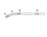
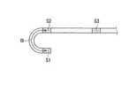
次に本実施形態における挿入部形状表示処理の詳細について説明する。図6、図7は、センサプローブ20が電子内視鏡10の鉗子チャンネルに装着され、それぞれアングルノブ11Aが操作され、挿入部12が湾曲された状態におけるセンサプローブ20の先端部付近の形状を示す模式図であり、図6は湾曲部12Bが僅かに曲げられたとき、図7は、先端部12Cの端面が略180°反転されるまで湾曲部12Bが曲げられた状態を示す。なお、図6、7には、センサプローブ20のみが描かれ、内視鏡挿入部12は省略されている。 Next, details of the insertion portion shape display processing in the present embodiment will be described. 6 and 7, the
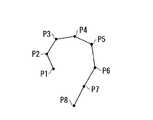
挿入部形状表示処理では、交流磁界を用いて求められた磁気センサ用コイルS1〜Snの位置に対応する点P1〜Pnを結ぶことにより、挿入部12の形状が画像表示装置41の画面に再現される。図8に点P1〜Pnの間を直線で結んだとき(直線補間)の状態を示し、図9に点P1〜Pnの間をベジェ曲線やスプライン曲線等の所定の曲線を用いて補間(フィッティング)したときの状態を示す。 In the insertion portion shape display process, the shape of the
湾曲部12Bは、一般に軟性部12Aとその構造が異なるとともに、アングルワイヤにより力が与えられなど力の掛かり方も大きく異なる。したがって、湾曲部12Bでは湾曲の仕方も軟性部12Aとは大きく異なり、従来のように湾曲部12Bでの補間に軟性部12Aと同じ方法を用いると、再現される湾曲部12Bの形状は実際のものと著しく異なる場合が発生する。 The
図10に、湾曲部12Bが大きく湾曲されたときの点P1〜P4の位置と、これらを直線補間したときの様子が示される。図10において、直線補間により再現された挿入部12Bの形状(点P1〜P4を直線で結んだもの)が実線Lsで示され、挿入部12の実際の形状が破線Lbで示される。 FIG. 10 shows the positions of the points P1 to P4 when the bending
図10に示されるように、軟性部12Aは、緩やかに撓むため軟性部12Aに対応する点P2〜点P4の間の区間では、再現された形状(Ls)と実際の形状(Lb)との間に余り大きな差はない。しかし、湾曲部12Bに対応する点P1〜点P2の間の再現形状は、実際の形状と大きく異なる。図10の例では、極端な例として直線補間の場合を挙げたが、ベジェ曲線やスプライン曲線を用いた補間においても、軟性部12Aと湾曲部12Bに同じ補間方法を用いる場合、湾曲部12Bが大きく湾曲されたときに対応することは出来ない。 As shown in FIG. 10, since the
湾曲部12Bの形状再現をより正確に行なうために、湾曲部12B内に多数の磁気センサを配置することも考えられるが、磁気センサ用のコイルが湾曲部12B内に配置されると、アングルノブ11Aによる湾曲操作が阻害されるだけでなく、センサが破壊される恐れがあり、センサプローブ20の耐久性が悪化する。 In order to more accurately reproduce the shape of the bending
これらのことから、図2、図3、図5を参照して説明されたように、本実施形態では第1センサS1と第2センサS2は、湾曲部12B(管状部21の先端部12Cの隣接部)の軸方向に沿って距離B離れて配置され、この距離Bは、湾曲部12Bの長さよりもわずかに長い。すなわち、センサプローブ20が鉗子チャンネル14に装着されると、第1センサS1は、リジッドな先端部12C内に配置され、第2コイルS2は、湾曲部12Bに隣接する軟性部12A内に配置され、湾曲部12B内に磁気センサ用コイルが配置されないように構成されている。 From these things, as demonstrated with reference to FIG.2, FIG.3, FIG.5, in this embodiment, 1st sensor S1 and 2nd sensor S2 are the
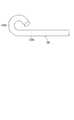
ところで、湾曲部12Bの湾曲の仕方は、一般に製品ごとに特徴がある。図11に湾曲部12Bの実際の湾曲状態と点P1の点P2に対する位置関係を模式的に示す。図11には湾曲部12Bが湾曲されていない状態から、湾曲部12Bが略反対向きにまで湾曲されるまでの状態が9つのステップとして描かれている。 By the way, the way of bending of the bending
図11において、9つの湾曲状態に対する点P1の各位置をP1(0)〜P1(8)とする。また、湾曲部12Bが湾曲されていないときに先端部12Cが向けられていた方向に対する湾曲時の先端部12Cの方向を角θで表わし、これにより湾曲部12Bの湾曲状態を表わす。すなわち、湾曲部12Bが湾曲されておらず、点P1がP1(0)に位置するときθ=0°であり、湾曲部12Bが反対向きにまで湾曲され、点P1がP1(8)に位置するときθ=180°である。また更に、位置P1(0)〜P1(8)でのθの値をそれぞれθ0〜θ8で表わす。 In FIG. 11, each position of the point P1 with respect to nine bending states is defined as P1 (0) to P1 (8). Further, the direction of the
このとき、点P1と点P2の間の距離(直線距離)Dと角度θとの間には通常1対1の対応関係がある(すなわち、D=D(θ)、θ=D-1(D))。また、先端部12Cがθ方向に向けられているときの湾曲部12Bの湾曲形状は、通常一通りである。したがって、点P1、点P2の位置から距離Dが決定されると、湾曲部12Bの形状を決定することができる。At this time, there is usually a one-to-one correspondence between the distance (linear distance) D between the points P1 and P2 and the angle θ (that is, D = D (θ), θ = D−1 ( D)). Further, the bending shape of the bending
本実施形態では、内視鏡10に対応したセンサプローブ20を用意し、センサプローブ20のコネクタ部24のメモリ24Mに、距離D(すなわち点P1の点P2に対する相対位置)と湾曲部12Bの形状の関係を示す情報が湾曲部形状データとして格納されている。なお、距離D(点P1の相対位置)に対する湾曲部12Bの形状は、予め計測されたものであり、湾曲部形状データの1例を表1に示す。 In this embodiment, the

表1に示されるように、湾曲部形状データは、例えば、各相対位置P1(0)〜P1(8)に対応して、湾曲部12Bの長手方向に沿った所定間隔の位置座標(x、y、z)が記録されている。表1に示された例では、点P1、P2間に対応する湾曲部12Bの位置座標データは、点P1、P2間を例えば10等分する間隔で用意され、P1(0)〜P1(8)毎に例えば9個の位置座標データ(X1、Y1、Z1)〜(X9、Y9、Z9)が記録されている。なお、図12に位置座標データ(X1、Y1、Z1)〜(X9、Y9、Z9)と湾曲部12Bとの関係を点P1がP1(0)、P1(4)、P1(8)に位置するときを例に模式的に示す。 As shown in Table 1, for example, the curved portion shape data corresponds to the relative coordinates P1 (0) to P1 (8), and the position coordinates (x, x) at predetermined intervals along the longitudinal direction of the
上述したように、距離Dが計算されると、点P2に対する点P1の相対位置(軸回りの自由度は考えない)は一意的に決定され、これに基づいて相対位置P1(0)〜P1(8)の何れかが選択され、そのときの位置座標データ(X1、Y1、Z1)〜(X9、Y9、Z9)に基づいて、湾曲部12Bの形状が再現される。 As described above, when the distance D is calculated, the relative position of the point P1 with respect to the point P2 (not considering the degree of freedom around the axis) is uniquely determined, and based on this, the relative positions P1 (0) to P1 are determined. One of (8) is selected, and the shape of the bending
本実施形態において湾曲部形状データは、点P1、P2間にある所定の点(1個以上)の位置情報であってもよいし、そのときの湾曲部12Bの曲率であってもよい。また、距離D毎に所定の補間関数や、補間関数のパラメータを格納しておいてもよく、以上のものを組み合わせたものであってもよい。 In the present embodiment, the bending portion shape data may be position information of a predetermined point (one or more) between the points P1 and P2, or may be the curvature of the bending
したがって、本実施形態の挿入部形状表示処理では、湾曲部12Bと軟性部12Aで異なる補間方法が採用され、これらを組み合わせることにより挿入部12全体の形状が再現される。すなわち、軟性部12Aに対しては、各コイルの位置をベジェ曲線やスプライン曲線などを用いて結び、従来の方法で挿入部12の形状が再現され、湾曲部12B、先端部12Cに対しては、予め湾曲部12Bにおける湾曲の仕方を調べた湾曲部形状データと、湾曲部12Bの両端に位置する軟性部12Aと先端部12Cに設けられた磁気センサ用コイルS1、S2の相対位置関係とに基づいて、補間が行なわれ形状が再現される。 Therefore, in the insertion portion shape display process of the present embodiment, different interpolation methods are adopted for the bending
なお、軟性部12Aの補間曲線にベジェ曲線やスプライン曲線などが用いられる場合、軟性部12Aの補間曲線の点P2に対する制御点は、湾曲部12Bに対し選択された補間曲線の接線や曲率などの幾何学的なパラメータを参照して決定される。 When a Bezier curve, a spline curve, or the like is used for the interpolation curve of the
以上のように、本実施形態によれば、簡略な構成で、より正確に湾曲部12Bの形状を再現することができ、これにより、挿入部全体の形状をより正確に再現することが可能となる。 As described above, according to the present embodiment, the shape of the bending
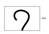
上記方法により求められた挿入部12の形状に対応する曲線を用いて画像表示装置41の画面41Aには、例えば図13に示されるように、挿入部12の輪郭形状が再現表示される。しかし、挿入部12の輪郭形状のみを表示した場合、表示された挿入部12と比較するものがないため、現実の大きさを把握することが難しいことから位置の把握も難しいものとなる。 The contour shape of the
これらのことから、本実施形態では、図14に示されるように、挿入部12の形状とともにセンサS1〜Snの位置を画面41A上に表示するモードを設けた。すなわち、本実施形態では、センサプローブ20の装着部22に設けられた画像表示切替ボタン22Cの操作に連動して、画面41Aにおける画像表示が図13から図14に、あるいは図14から図13へと切り替え可能である。 Accordingly, in the present embodiment, as shown in FIG. 14, a mode for displaying the positions of the sensors S <b> 1 to Sn together with the shape of the
以上により、施術者はセンサS1〜Snの相対的な位置関係から、画面に表示された挿入部12の大きさを大まかに把握することが可能となる。 As described above, the practitioner can roughly grasp the size of the
また、内視鏡の挿入部には、先端部12Cからの長さを示す指標が所定の長さ(例えば10cm)置きに記されているのが一般的である。したがって、図14の表示に代え、求められた補間曲線に沿った先端12Cからの距離を算出し、指標が描かれた位置に対応する位置に対応する指標を示すマークを図15のように表示するモードを設けることも可能である。 In general, an index indicating the length from the
また更に、図16に示されるように、内視鏡挿入部12の指標N1〜Nnが設けられる位置に合わせてセンサS1〜Snが配置されるように、センサプローブ20においてセンサS1〜Snを配置し、先端部12Cからの距離の計算を行なうことなく図15の表示を直接行なえるようにしてもよい。 Furthermore, as shown in FIG. 16, the sensors S1 to Sn are arranged in the
なお本実施形態では、位置検出装置本体が再現画像のデータを作成する装置としても使用され、画像表示装置が直接接続された。しかし、磁気センサ用コイルの位置情報をコンピュータに出力し、コンピュータにおいて、挿入部の形状を再現し画面表示を行なってもよい。 In the present embodiment, the position detection device main body is also used as a device for creating reproduced image data, and the image display device is directly connected. However, the position information of the magnetic sensor coil may be output to a computer, and the computer may reproduce the shape of the insertion portion and display the screen.
また本実施形態では、センサプローブに設けられたメモリに湾曲形状データが格納されたが、例えば位置検出装置本体やコンピュータのメモリに格納されていてもよい。このような場合には、例えばセンサプローブや内視鏡の種類(型番)毎に湾曲形状データをメモリに格納しておき、センサプローブ、内視鏡の型番を画面上にリスト表示し、これらの中から対応する型番を選択することにより対応する湾曲形状データを取得する構成としてもよい。また、型番をセンサプローブのメモリに記録しておき、これを読み出して型番に対応する湾曲形状データを自動選択する構成としてもよい。 In the present embodiment, the curved shape data is stored in the memory provided in the sensor probe. However, the curved shape data may be stored in the memory of the position detection device main body or the computer, for example. In such a case, for example, the curved shape data is stored in the memory for each type (model number) of the sensor probe and endoscope, and the model numbers of the sensor probe and endoscope are displayed in a list on the screen. It is good also as a structure which acquires corresponding curve shape data by selecting a corresponding model number from the inside. Alternatively, the model number may be recorded in the memory of the sensor probe, read out, and the curved shape data corresponding to the model number may be automatically selected.
本実施形態では、外部に設置された磁場発生器により生成された交流磁界をプローブに設けられたセンサ用のコイルを用いて検出したが、磁界発生用のコイルをプローブに設け、これを外部に設置されたセンサで検出する構成としてもよい。また、本実施形態では、鉗子チャンネルにセンサプローブを装着する構成としたが、センサプローブが挿入されるチャンネルは、これに限定されるものではない。またセンサコイルを内視鏡の挿入部内に直接設けることも可能である。 In the present embodiment, the AC magnetic field generated by the magnetic field generator installed outside is detected using the sensor coil provided on the probe. However, the magnetic field generating coil is provided on the probe, and this is externally provided. It is good also as a structure detected with the installed sensor. In this embodiment, the sensor probe is attached to the forceps channel, but the channel into which the sensor probe is inserted is not limited to this. It is also possible to provide the sensor coil directly in the insertion part of the endoscope.
また本実施形態では、湾曲部の湾曲状態が第1センサと第2センサの間の距離によって一意的に決定されるものとし、この距離のみに基づいて湾曲部の状態を判定し湾曲部形状データの参照が行なわれたが、距離の違いによる判定が困難な場合には、更に第1及び第2センサにより検出されるそれぞれのセンサの方向を判定に取り入れてもよい。 Further, in the present embodiment, the bending state of the bending portion is uniquely determined by the distance between the first sensor and the second sensor, and the bending portion state data is determined by determining the state of the bending portion based only on this distance. However, if it is difficult to make a determination due to a difference in distance, the directions of the respective sensors detected by the first and second sensors may be taken into the determination.
10 内視鏡
11B 鉗子口
12 挿入部
12A 軟性部
12B 湾曲部
12C 先端部
20 センサプローブ
21 管状部
24M メモリ
26 信号処理回路
27 制御演算部
28 画像表示制御部
29 駆動回路XYZ
40 磁場発生器
41 画像表示装置
S1〜Sn センサ(コイル)
DESCRIPTION OF
40
Claims (18)
Translated fromJapanese前記挿入部の位置情報を所定間隔毎に検出する位置検出手段と、
前記位置検出手段により検出された挿入部の位置情報から、前記挿入部の形状を再現する形状再現手段と、
前記形状再現手段により求められた前記挿入部の再現形状を表示する画像表示手段とを備え、
前記画像表示手段における画像表示において、前記再現形状に沿って、前記再現形状の大きさの把握を可能にするマークを表示する
ことを特徴とする内視鏡挿入部形状把握システム。An endoscope insertion portion shape grasping system for grasping the shape of a flexible endoscope insertion portion,
Position detecting means for detecting position information of the insertion portion at predetermined intervals;
From the position information of the insertion portion detected by the position detection means, shape reproduction means for reproducing the shape of the insertion portion,
Image display means for displaying the reproduction shape of the insertion portion determined by the shape reproduction means,
In the image display in the image display means, a mark that enables the size of the reproduced shape to be grasped is displayed along the reproduced shape.
前記距離に対応して、前記湾曲部の形状を再現するための湾曲部形状データを格納するメモリと
を備えることを特徴とする請求項1に記載の内視鏡挿入部形状把握システム。Distance detecting means for detecting a distance between both ends of the bending portion in the insertion portion;
The endoscope insertion portion shape grasping system according to claim 1, further comprising: a memory that stores bending portion shape data for reproducing the shape of the bending portion corresponding to the distance.
The endoscope insertion according to claim 17, wherein the soft part shape reproducing means is reproduced by using an interpolation curve connecting positions of a plurality of sensors arranged along a longitudinal direction of the soft part. Part shape grasping system.
Priority Applications (1)
| Application Number | Priority Date | Filing Date | Title |
|---|---|---|---|
| JP2005324531AJP2007130132A (en) | 2005-11-09 | 2005-11-09 | Endoscope insertion part shape grasping system |
Applications Claiming Priority (1)
| Application Number | Priority Date | Filing Date | Title |
|---|---|---|---|
| JP2005324531AJP2007130132A (en) | 2005-11-09 | 2005-11-09 | Endoscope insertion part shape grasping system |
Publications (1)
| Publication Number | Publication Date |
|---|---|
| JP2007130132Atrue JP2007130132A (en) | 2007-05-31 |
Family
ID=38152292
Family Applications (1)
| Application Number | Title | Priority Date | Filing Date |
|---|---|---|---|
| JP2005324531AWithdrawnJP2007130132A (en) | 2005-11-09 | 2005-11-09 | Endoscope insertion part shape grasping system |
Country Status (1)
| Country | Link |
|---|---|
| JP (1) | JP2007130132A (en) |
Cited By (5)
| Publication number | Priority date | Publication date | Assignee | Title |
|---|---|---|---|---|
| JP2011523576A (en)* | 2008-06-06 | 2011-08-18 | マイクロポート メディカル (シャンハイ) カンパニー リミテッド | Method for simulating curved shape of catheter and magnetic guiding catheter |
| WO2012119694A1 (en)* | 2011-03-08 | 2012-09-13 | Olympus Winter & Ibe Gmbh | Method and system for displaying video-endoscopic image data of a video endoscope |
| JP2017225866A (en)* | 2012-02-03 | 2017-12-28 | インテュイティブ サージカル オペレーションズ, インコーポレイテッド | Steerable flexible needle with embedded shape sensing function |
| CN110856648A (en)* | 2018-08-24 | 2020-03-03 | 富士胶片株式会社 | Display control device, endoscope system, display control method, and program therefor |
| CN111031885A (en)* | 2017-08-29 | 2020-04-17 | 乔伊马克斯有限责任公司 | Endoscope device |
Citations (3)
| Publication number | Priority date | Publication date | Assignee | Title |
|---|---|---|---|---|
| JPH08542A (en)* | 1994-04-21 | 1996-01-09 | Olympus Optical Co Ltd | Endoscope position detector |
| JPH10332309A (en)* | 1997-05-29 | 1998-12-18 | Olympus Optical Co Ltd | Measuring method for coil position |
| JP2000175862A (en)* | 1998-12-17 | 2000-06-27 | Olympus Optical Co Ltd | Endoscope inserted shape detecting device |
- 2005
- 2005-11-09JPJP2005324531Apatent/JP2007130132A/ennot_activeWithdrawn
Patent Citations (3)
| Publication number | Priority date | Publication date | Assignee | Title |
|---|---|---|---|---|
| JPH08542A (en)* | 1994-04-21 | 1996-01-09 | Olympus Optical Co Ltd | Endoscope position detector |
| JPH10332309A (en)* | 1997-05-29 | 1998-12-18 | Olympus Optical Co Ltd | Measuring method for coil position |
| JP2000175862A (en)* | 1998-12-17 | 2000-06-27 | Olympus Optical Co Ltd | Endoscope inserted shape detecting device |
Cited By (17)
| Publication number | Priority date | Publication date | Assignee | Title |
|---|---|---|---|---|
| JP2011523576A (en)* | 2008-06-06 | 2011-08-18 | マイクロポート メディカル (シャンハイ) カンパニー リミテッド | Method for simulating curved shape of catheter and magnetic guiding catheter |
| WO2012119694A1 (en)* | 2011-03-08 | 2012-09-13 | Olympus Winter & Ibe Gmbh | Method and system for displaying video-endoscopic image data of a video endoscope |
| US9510735B2 (en) | 2011-03-08 | 2016-12-06 | Olympus Winter & Ibe Gmbh | Method and system for displaying video-endoscopic image data of a video endoscope |
| US11583204B2 (en) | 2012-02-03 | 2023-02-21 | Intuitive Surgical Operations, Inc. | Steerable flexible needle with embedded shape sensing |
| JP2017225866A (en)* | 2012-02-03 | 2017-12-28 | インテュイティブ サージカル オペレーションズ, インコーポレイテッド | Steerable flexible needle with embedded shape sensing function |
| US12295718B2 (en) | 2012-02-03 | 2025-05-13 | Intuitive Surgical Operations, Inc. | Steerable flexible needle with embedded shape sensing |
| US10638953B2 (en) | 2012-02-03 | 2020-05-05 | Intuitive Surgical Operations, Inc. | Steerable flexible needle with embedded shape sensing |
| JP7329248B2 (en) | 2017-08-29 | 2023-08-18 | ジョイマックス ゲーエムベーハー | endoscope device |
| KR20200047536A (en)* | 2017-08-29 | 2020-05-07 | 요이막스 게엠베하 | Endoscopic device |
| JP2020532332A (en)* | 2017-08-29 | 2020-11-12 | ジョイマックス ゲーエムベーハー | Endoscope device |
| KR20200047537A (en)* | 2017-08-29 | 2020-05-07 | 요이막스 게엠베하 | Detection system and method for automatic detection of surgical instruments |
| US11647891B2 (en) | 2017-08-29 | 2023-05-16 | Joimax Gmbh | Endoscope device |
| CN111031885A (en)* | 2017-08-29 | 2020-04-17 | 乔伊马克斯有限责任公司 | Endoscope device |
| CN111031885B (en)* | 2017-08-29 | 2023-09-12 | 乔伊马克斯有限责任公司 | Endoscope apparatus |
| KR102577934B1 (en) | 2017-08-29 | 2023-09-14 | 요이막스 게엠베하 | Detection system and method for automatic detection of surgical instruments |
| KR102612012B1 (en)* | 2017-08-29 | 2023-12-11 | 요이막스 게엠베하 | endoscope device |
| CN110856648A (en)* | 2018-08-24 | 2020-03-03 | 富士胶片株式会社 | Display control device, endoscope system, display control method, and program therefor |
Similar Documents
| Publication | Publication Date | Title |
|---|---|---|
| US6589163B2 (en) | Endoscope shape detecting apparatus wherein form detecting processing is controlled according to connection state of magnetic field generating means | |
| JP4709946B2 (en) | MEDICAL DEVICE SYSTEM AND MEDICAL DEVICE CALIBRATION METHOD | |
| US20070106114A1 (en) | Endoscope-shape monitoring system | |
| CN102939040B (en) | Probe shape detection device and probe shape detection method | |
| EP1354557A1 (en) | Ultrasonic diagnostic apparatus and method | |
| JP4827495B2 (en) | Endoscope insertion part shape grasping system | |
| US20070106115A1 (en) | Endoscope-shape monitoring system | |
| JP2001046318A (en) | Endoscope shape detector | |
| EP2572625B1 (en) | Probe-shape detecting apparatus and probe-shape detecting method | |
| JP3290153B2 (en) | Endoscope insertion shape detection device | |
| JP4708963B2 (en) | Endoscope insertion part shape grasping system | |
| CN101026988A (en) | Bending control device | |
| JP2007130132A (en) | Endoscope insertion part shape grasping system | |
| WO2006051949A1 (en) | Endoscope profile detector | |
| JP2007130175A (en) | Endoscope insertion part shape grasping system | |
| JP4142189B2 (en) | Endoscope shape detection system | |
| JP5160619B2 (en) | Endoscope shape detection device | |
| JP6429618B2 (en) | Endoscope insertion shape observation device | |
| JP3458060B2 (en) | Endoscope shape detection device and endoscope shape display control method | |
| JP4647972B2 (en) | Endoscope shape detection device | |
| JP4708962B2 (en) | Endoscope insertion part shape grasping system | |
| JP2007130151A (en) | Endoscope insertion part shape grasping system | |
| JP2009090023A (en) | Endoscope shape analyzer | |
| JP6464110B2 (en) | Endoscope shape grasp system | |
| JP4699068B2 (en) | Endoscope shape detection device |
Legal Events
| Date | Code | Title | Description |
|---|---|---|---|
| A621 | Written request for application examination | Free format text:JAPANESE INTERMEDIATE CODE: A621 Effective date:20071212 | |
| A711 | Notification of change in applicant | Free format text:JAPANESE INTERMEDIATE CODE: A712 Effective date:20080501 | |
| A977 | Report on retrieval | Free format text:JAPANESE INTERMEDIATE CODE: A971007 Effective date:20100629 | |
| A131 | Notification of reasons for refusal | Free format text:JAPANESE INTERMEDIATE CODE: A131 Effective date:20100706 | |
| A761 | Written withdrawal of application | Free format text:JAPANESE INTERMEDIATE CODE: A761 Effective date:20100906 |