JP2007129658A - Portable terminal device and power exchange method - Google Patents
Portable terminal device and power exchange methodDownload PDFInfo
- Publication number
- JP2007129658A JP2007129658AJP2005322591AJP2005322591AJP2007129658AJP 2007129658 AJP2007129658 AJP 2007129658AJP 2005322591 AJP2005322591 AJP 2005322591AJP 2005322591 AJP2005322591 AJP 2005322591AJP 2007129658 AJP2007129658 AJP 2007129658A
- Authority
- JP
- Japan
- Prior art keywords
- terminal device
- battery
- portable terminal
- secondary coil
- power
- Prior art date
- Legal status (The legal status is an assumption and is not a legal conclusion. Google has not performed a legal analysis and makes no representation as to the accuracy of the status listed.)
- Withdrawn
Links
- 238000000034methodMethods0.000titleclaimsabstractdescription11
- 230000005540biological transmissionEffects0.000claimsdescription8
- 230000006698inductionEffects0.000claimsdescription6
- 230000010355oscillationEffects0.000claimsdescription6
- 230000005672electromagnetic fieldEffects0.000claimsdescription4
- 238000007599dischargingMethods0.000claims2
- 230000001413cellular effectEffects0.000description3
- 238000010586diagramMethods0.000description2
- 229920001690polydopaminePolymers0.000description2
- 238000007796conventional methodMethods0.000description1
- 230000005674electromagnetic inductionEffects0.000description1
Images


Landscapes
- Charge And Discharge Circuits For Batteries Or The Like (AREA)
- Telephone Set Structure (AREA)
- Mobile Radio Communication Systems (AREA)
- Telephone Function (AREA)
Abstract
Description
Translated fromJapanese本発明は、例えば携帯電話端末やPDA(Personal Digital Assistant)等の携帯端末装置及び携帯端末装置間で電力を伝送するための電力送受電方法に関する。 The present invention relates to a mobile terminal device such as a mobile phone terminal or PDA (Personal Digital Assistant) and a power transmission / reception method for transmitting power between the mobile terminal devices.
近年は、携帯電話端末やPDA等のような小型の携帯端末装置が広く普及している。これらの携帯端末装置は、一般に、充電可能なバッテリから供給される電力により動作するものであり、当該バッテリへの充電は、その携帯端末装置専用の充電装置により行われている。 In recent years, small mobile terminal devices such as mobile phone terminals and PDAs have become widespread. These portable terminal devices generally operate using electric power supplied from a rechargeable battery, and charging of the battery is performed by a charging device dedicated to the portable terminal device.
最近では、これらの携帯端末装置に様々な機能が搭載され、使用する電力量は著しく増加してきている。そのため、外出先などにおいて携帯端末装置を長時間使用したりすると、バッテリ電圧が低下し、電源が切れてしまうことがある。例えば、携帯電話端末では、本来の電話機能の他にアドレス帳やメモ帳など、手帳に代った利用もされているが、電源が切れてしまうとその閲覧すらも不可能になり、使用者にとっては大変不便である。 Recently, various functions are installed in these portable terminal devices, and the amount of power used has increased remarkably. For this reason, when the mobile terminal device is used for a long time in places such as going out, the battery voltage may drop and the power may be turned off. For example, mobile phone terminals are used in place of notebooks such as address book and memo pad in addition to the original telephone function, but when the power is turned off, even browsing is impossible. It is very inconvenient for me.
従来は、外出先などでバッテリの充電を行うための方法として、携帯用の充電装置と乾電池を使用して充電する方法や、充電装置を用いて商用電源から充電する方法などがあった。しかし、これらの方法では、充電のための外部装置を携帯しておく必要があり、更に後者では、充電可能な商用電源のコンセント等を確保する必要があるため、充電を行える場所が限定されるなどの問題があった。 Conventionally, as a method for charging a battery while away from home, there are a method of charging using a portable charging device and a dry battery, a method of charging from a commercial power source using a charging device, and the like. However, in these methods, it is necessary to carry an external device for charging, and in the latter case, it is necessary to secure an outlet for a commercial power source that can be charged, so that the places where charging can be performed are limited. There were problems such as.
そのため、携帯端末装置の内部に一次コイルと二次コイルを設け、バッテリ残容量がなくなった携帯端末装置の二次コイルに他のバッテリ残容量の多い携帯端末装置の一次コイルを近づけることにより、電磁誘導を用いてバッテリを充電する、無接点方式の充電方法が提案されている。 Therefore, by providing a primary coil and a secondary coil inside the mobile terminal device, and bringing the primary coil of another mobile terminal device with a large remaining battery capacity close to the secondary coil of the mobile terminal device that has no remaining battery capacity, A contactless charging method for charging a battery using induction has been proposed.
特許文献1には、放電可能な自機バッテリの残容量を検知しておき、他の携帯端末装置が近接してきたことを検知すると、他の携帯端末装置のバッテリ残容量を検知して、バッテリの残要領の多い装置が電力を外部へ出力し、バッテリの残要領の少ない装置が無接点方式で自機バッテリを充電するように、自動的に切り替え制御できる携帯型電子装置の例についての開示がある。
ところで、無接点方式による充電は、対面する一次コイルと二次コイルの位置により、取り出せる電力量は大きく変化する。そのため、携帯電話端末などのバッテリ容量の小さい装置の場合、バッテリ残容量がなくなり電源が切れてしまった装置の電源を、再度入れて起動できるようにするために十分な充電を行うことは難しいという問題があった。 By the way, in the charge by the non-contact method, the amount of electric power that can be taken out varies greatly depending on the positions of the primary coil and the secondary coil facing each other. Therefore, in the case of a device with a small battery capacity, such as a mobile phone terminal, it is difficult to fully charge the device so that it can be turned on again and started after the remaining battery capacity has been exhausted and the power has been turned off. There was a problem.
本発明は、外出先など、専用の充電装置が無い環境下へ携帯端末装置を持ち出して使用するような場合において、バッテリ残容量がなくなった携帯端末装置のバッテリを、充分な残容量がある携帯端末装置から無接点充電することにより、使用可能にすることができる、携帯端末装置、及び、携帯端末装置間で電力を伝送するための電力送受電方法を提供することを目的とする。 In the case where the portable terminal device is taken out and used in an environment where there is no dedicated charging device, such as a place where the user is away from home, the battery of the portable terminal device that has no remaining battery capacity is used as a portable device having a sufficient remaining capacity. It aims at providing the power transmission / reception method for transmitting electric power between the portable terminal device and portable terminal device which can be used by non-contact charge from a terminal device.
本発明は、携帯端末装置の筐体の所定面に凹部と凸部を設け、例えば、携帯端末装置の筐体に設けた窪みの底辺の部分の内側に一次コイルを内蔵し、筐体から突出するように設けた凸部分の内部に二次コイルを内蔵するように構成したものである。 The present invention provides a concave portion and a convex portion on a predetermined surface of a casing of a mobile terminal device, for example, a primary coil is incorporated inside a bottom portion of a recess provided in the casing of the mobile terminal device, and protrudes from the casing. The secondary coil is built in the convex portion provided as described above.
このように携帯端末装置の筐体に凹凸を設けることで、充電時には電力を供給する側の携帯端末装置の凹部に、バッテリを充電する側の携帯端末装置の凸部を差し込むことにより、一次コイルと二次コイルの位置を固定することが可能になる。 In this way, by providing irregularities in the casing of the mobile terminal device, the primary coil is inserted by inserting the convex portion of the mobile terminal device on the battery charging side into the concave portion of the mobile terminal device on the power supply side during charging. And the position of the secondary coil can be fixed.
本発明によると、専用の充電装置を用いることなく携帯端末装置間で無接点充電することが可能になる。更に、携帯端末装置間で無接点充電する場合に、一次コイルと二次コイルの位置を固定することが可能になるため、従来の方法よりも充電の効率を向上させることが可能になる。 According to the present invention, it is possible to perform contactless charging between portable terminal devices without using a dedicated charging device. Furthermore, since the positions of the primary coil and the secondary coil can be fixed when contactless charging is performed between portable terminal devices, the charging efficiency can be improved as compared with the conventional method.
また、充電する場合に、携帯端末装置の筐体に設けた凹凸のガイドに従って差し込めばよいため、筐体の位置関係を気にすることなく簡単に充電が可能となる。また、一つの携帯端末装置の中に一次コイルと二次コイルを内蔵するため、送電/受電のどちらも可能となる。 In addition, when charging, it is only necessary to insert the guide according to the uneven guide provided on the casing of the portable terminal device, so that charging can be easily performed without worrying about the positional relationship of the casing. Moreover, since the primary coil and the secondary coil are built in one portable terminal device, both power transmission and power reception are possible.
以下、本発明の一実施の形態を、図1〜図3を参照して説明する。 Hereinafter, an embodiment of the present invention will be described with reference to FIGS.
本例の携帯端末装置は、例えば携帯電話端末やPDA、ノート型パーソナルコンピュータ(パソコン)などに適用可能であり、図1は、携帯電話端末に適用した場合の全体構成例を示す。 The mobile terminal device of this example is applicable to, for example, a mobile phone terminal, a PDA, a notebook personal computer (personal computer), etc. FIG. 1 shows an example of the overall configuration when applied to a mobile phone terminal.
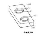
図1において、携帯電話端末10の筐体の背面に筐体から突出した凸部13を設け、その内部に二次コイル28を内蔵している。また、凸部13と同じ面に凹部14を設け、その窪みの底部に一次コイル21を内蔵している。凸部13は凹部14の窪みにはめ込むことができる形状とし、凹凸の高さ及び位置は、使用者が携帯電話端末を操作する場合に操作の支障にならない程度の高さになるよう構成する。例えば、凸部13はバッテリパックを収納する蓋の部分に設け、高さは約5mm程度とする。また、本例では、凹凸部の形状を円形としているが、凸部の内部にコイルが収納可能で、凹部と凸部を組み合わせることができれば、どのような形状でも可能である。なお、携帯電話端末10の表面などには、電話機として必要な部品(操作キー、表示パネルなど)を配置しているが、それらが一般的に備えている他の構成については図示及び説明を省略する。 In FIG. 1, a
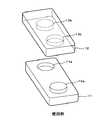
次に図2を参照して、携帯電話端末11を用いて携帯電話端末12を充電する場合について説明する。携帯電話端末11の筐体の背面には、二次コイルを内蔵した凸部13aと、一次コイルを内蔵した凹部14aを設ける。携帯電話端末12には、携帯電話端末11と同様に二次コイルを内蔵した凸部13bと一次コイルを内蔵した凹部14bを設ける。携帯電話端末11による充電は、携帯電話端末11の背面と携帯電話端末12の背面を向き合わせ、携帯電話端末11の凹部14aと携帯電話端末12の凸部13bとが互いに組み合わさるように近づける。そして互いの凹凸のガイドに従って差し込んだ状態で配置することにより、一次コイルと二次コイルの位置を固定することができる。この状態で携帯電話端末11から携帯電話端末12への無接点充電を行う。 Next, with reference to FIG. 2, the case where the
図3は、本例の内部構成のうち、電力の送受電を行う機能を実現する部分の構成を示すブロック図である。携帯電話端末10の内部には、携帯電話端末10の各部へ電力を供給するための二次電池であるバッテリ25がある。このバッテリ25を用いて電力の送受電を行うため、バッテリ25に接続する送電側の機器と、受電側の機器とを構成している。送電側の構成としては、バッテリ25は、スイッチ24を介して昇圧器23に接続し、昇圧器23から発振回路22を介して電力を放電する一次コイル21に接続している。受電側の構成としては、電力を受電する二次コイル28は、整流器27を介してレギュレータ26に接続し、レギュレータ26はバッテリ25に接続するよう構成する。 FIG. 3 is a block diagram illustrating a configuration of a portion that realizes a function of transmitting and receiving power in the internal configuration of this example. Inside the
次に、電力の送電を行う場合について説明する。携帯電話端末10を送電器として使用するときは、まずスイッチ24を入り状態にする。スイッチ24は、携帯電話端末10の外部に設け、使用者が機械的に入り/切りの操作を行うように構成する場合や、携帯電話端末10に備えた表示部(図示せず)にメニューなどの表示を行い、携帯電話端末10に設けられている操作釦(図示せず)を用いてスイッチの入り/切りを選択するように構成してもよい。スイッチ24を入り状態にすると、スイッチ24を介してバッテリ25から昇圧器23に電力が入力される。昇圧器23は、入力された電力を発振回路22の入力に必要な電圧になるまで昇圧し、発振回路22へ入力する。発振回路22は、入力された直流電流を交流電流に変換し、一次コイル21へ入力する。このようにして、一次コイル21から携帯電話端末10の外部へ誘導電磁界を発生させることができる。 Next, a case where power transmission is performed will be described. When the
次に、電力を受電する場合について説明する。電力を受電する場合は、携帯電話端末10に送電器として用いる携帯電話端末を近づけ、上記説明したように、携帯電話端末の凹凸部を組み合わせるようにする。すると、送電器となる携帯電話端末の一次コイルから発生した誘導電磁界に、受電側となる携帯電話端末10の二次コイル28が入るため、二次コイル28にはその誘導電磁界からの電磁誘導により、極性の異なる起電力が交互に発生する。そして、二次コイル28で発生した起電力により、二次コイル28から交流電流が発生し、その交流電流は整流器27へ入力される。整流器27は、入力された交流電流を直流電流へ変換し、レギュレータ26へ供給する。レギュレータ26で定電圧化した電圧をバッテリ25へ供給し、バッテリ25を充電する。 Next, a case where power is received will be described. When receiving electric power, the cellular phone terminal used as a power transmitter is brought close to the
このようにして、充電のための外部装置なしで、携帯電話端末などの携帯端末装置の充電を行うことができるが、筐体に設けた凹凸部のガイドにより、一次コイルと二次コイルの位置が固定できるため、電磁誘導を用いた充電を効率よく行うことができる。 In this way, it is possible to charge a mobile terminal device such as a mobile phone terminal without an external device for charging, but the positions of the primary coil and the secondary coil are guided by the guides of the concave and convex portions provided on the housing. Therefore, charging using electromagnetic induction can be performed efficiently.
なお、ここまで説明した実施の形態では、携帯端末装置としてスティック型の携帯電話端末に適用した例について説明したが、これに限定されず、折りたたみ式の携帯電話端末に適用することも可能である。図4は、折りたたみ式の携帯電話端末30に適用した場合の構成例を示している。携帯電話端末30の背面には、二次コイルを内蔵した凸部13cと、一次コイルを内蔵した凹部14cを設ける。この凹凸部を差し込むことにより、充電側装置と送電側装置とを組み合わせて固定し、充電することができる。 In the embodiment described so far, an example in which the mobile terminal device is applied to a stick-type mobile phone terminal has been described. However, the present invention is not limited to this and can be applied to a foldable mobile phone terminal. . FIG. 4 shows a configuration example when applied to a foldable
また、上述した実施の形態では、一次コイルを凹部14に内蔵させ、二次コイルを凸部13に内蔵させた例としたが、逆に、一次コイルを凸部13に内蔵させ、二次コイルを凹部14に内蔵させた構成としてもよい。 In the above-described embodiment, the primary coil is built in the
また、本発明は、携帯電話端末に限らず、バッテリを搭載した携帯型の装置であれば適用が可能である。例えば、PDAやノート型パーソナルコンピュータ(パソコン)、デジタルカメラなど、様々な機器に適用できる。 In addition, the present invention is not limited to a mobile phone terminal, and can be applied to any portable device equipped with a battery. For example, the present invention can be applied to various devices such as PDAs, notebook personal computers (personal computers), and digital cameras.
10,11,12,30…携帯電話端末、13,13a,13b,13c…凸部、14,14a,14b,14c…凹部、21…一次コイル、22…発振回路、23…昇圧器、24…スイッチ、25…バッテリ、26…レギュレータ、27…整流器、28…二次コイル DESCRIPTION OF
Claims (3)
Translated fromJapanese筐体の所定面に凹部と凸部を設け、
前記凹部の底部内側に一次コイル又は二次コイルを内蔵し、
前記凸部の内部に二次コイル又は一次コイルを内蔵し、
前記一次コイルは、スイッチを介して前記バッテリと接続する昇圧器と、昇圧器に接続する発振回路を経由して前記バッテリに接続するよう構成し、
前記二次コイルは、整流器と、整流器に接続するレギュレータを経由して前記バッテリに接続するよう構成し、
自機の凸部と他機の凹部又は自機の凹部と他機の凸部とを組み合わせることにより、自機又は他機のバッテリを充電することを特徴とする
携帯端末装置。In a portable terminal device equipped with a battery,
Providing concave and convex portions on a predetermined surface of the housing,
A primary coil or a secondary coil is built inside the bottom of the recess,
A secondary coil or a primary coil is built in the convex part,
The primary coil is configured to be connected to the battery via a booster connected to the battery via a switch and an oscillation circuit connected to the booster,
The secondary coil is configured to be connected to the battery via a rectifier and a regulator connected to the rectifier,
A portable terminal device that charges a battery of the own device or the other device by combining the convex portion of the own device and the concave portion of the other device or the concave portion of the own device and the convex portion of the other device.
前記バッテリに接続するスイッチを入り状態にすることで、前記バッテリから前記昇圧器へ電力を入力して昇圧し、昇圧した電力を前記発振回路へ入力して発生させた交流電流を前記一次コイルへ供給することにより放電する、電力の放電手段と、
前記二次コイルを誘導電磁界に入れることにより、前記二次コイルに起電力が発生して交流電流が発生し、発生した交流電流を整流器に入力して直流電流へ変換し、変換した直流電流をレギュレータにより定電圧化して前記バッテリを充電する、充電手段とを備えた
携帯端末装置。The mobile terminal device according to claim 1,
By switching on the switch connected to the battery, power is input from the battery to the booster to boost the voltage, and the alternating current generated by inputting the boosted power to the oscillation circuit is supplied to the primary coil. Electric power discharging means for discharging by supplying,
By placing the secondary coil in an induction electromagnetic field, an electromotive force is generated in the secondary coil and an alternating current is generated. The generated alternating current is input to a rectifier and converted into a direct current, and the converted direct current is generated. A portable terminal device comprising charging means for charging the battery by making the voltage constant with a regulator.
電力送受電方法。
A concave portion or a convex portion provided in the casing of the first portable terminal device on which the battery that can be discharged is mounted, and a convex portion or a concave portion provided in the casing of the second portable terminal device in which the battery voltage is reduced. In combination, by turning on a switch provided in the first portable terminal device, the primary coil built in the bottom surface of the concave or convex portion of the first portable terminal device, and the second portable A power transmission / reception method in which the battery of the second portable terminal device is contactlessly charged via a secondary coil of the terminal device.
Priority Applications (1)
| Application Number | Priority Date | Filing Date | Title |
|---|---|---|---|
| JP2005322591AJP2007129658A (en) | 2005-11-07 | 2005-11-07 | Portable terminal device and power exchange method |
Applications Claiming Priority (1)
| Application Number | Priority Date | Filing Date | Title |
|---|---|---|---|
| JP2005322591AJP2007129658A (en) | 2005-11-07 | 2005-11-07 | Portable terminal device and power exchange method |
Publications (1)
| Publication Number | Publication Date |
|---|---|
| JP2007129658Atrue JP2007129658A (en) | 2007-05-24 |
Family
ID=38151921
Family Applications (1)
| Application Number | Title | Priority Date | Filing Date |
|---|---|---|---|
| JP2005322591AWithdrawnJP2007129658A (en) | 2005-11-07 | 2005-11-07 | Portable terminal device and power exchange method |
Country Status (1)
| Country | Link |
|---|---|
| JP (1) | JP2007129658A (en) |
Cited By (7)
| Publication number | Priority date | Publication date | Assignee | Title |
|---|---|---|---|---|
| JP2009148151A (en)* | 2007-12-12 | 2009-07-02 | Lg Electronics Inc | Mobile terminal having wireless charging menu providing function and wireless charging method thereof |
| JP2010011696A (en)* | 2008-06-30 | 2010-01-14 | Mitsui Eng & Shipbuild Co Ltd | Non-contact power supply system for ships, ship and ship power supply method |
| JP2012143148A (en)* | 2007-03-02 | 2012-07-26 | Qualcomm Inc | Wireless power apparatus and methods |
| US8629576B2 (en) | 2008-03-28 | 2014-01-14 | Qualcomm Incorporated | Tuning and gain control in electro-magnetic power systems |
| US9124120B2 (en) | 2007-06-11 | 2015-09-01 | Qualcomm Incorporated | Wireless power system and proximity effects |
| US9130602B2 (en) | 2006-01-18 | 2015-09-08 | Qualcomm Incorporated | Method and apparatus for delivering energy to an electrical or electronic device via a wireless link |
| US11983037B2 (en) | 2012-03-14 | 2024-05-14 | Popsockets Llc | Gaming controller docking accessory for mobile electronic devices |
- 2005
- 2005-11-07JPJP2005322591Apatent/JP2007129658A/ennot_activeWithdrawn
Cited By (11)
| Publication number | Priority date | Publication date | Assignee | Title |
|---|---|---|---|---|
| US9130602B2 (en) | 2006-01-18 | 2015-09-08 | Qualcomm Incorporated | Method and apparatus for delivering energy to an electrical or electronic device via a wireless link |
| JP2012143148A (en)* | 2007-03-02 | 2012-07-26 | Qualcomm Inc | Wireless power apparatus and methods |
| US9774086B2 (en) | 2007-03-02 | 2017-09-26 | Qualcomm Incorporated | Wireless power apparatus and methods |
| US9124120B2 (en) | 2007-06-11 | 2015-09-01 | Qualcomm Incorporated | Wireless power system and proximity effects |
| JP2009148151A (en)* | 2007-12-12 | 2009-07-02 | Lg Electronics Inc | Mobile terminal having wireless charging menu providing function and wireless charging method thereof |
| KR101432590B1 (en)* | 2007-12-12 | 2014-08-21 | 엘지전자 주식회사 | A mobile terminal having a wireless charging menu providing function and a charging method thereof |
| US8629576B2 (en) | 2008-03-28 | 2014-01-14 | Qualcomm Incorporated | Tuning and gain control in electro-magnetic power systems |
| JP2010011696A (en)* | 2008-06-30 | 2010-01-14 | Mitsui Eng & Shipbuild Co Ltd | Non-contact power supply system for ships, ship and ship power supply method |
| US11983037B2 (en) | 2012-03-14 | 2024-05-14 | Popsockets Llc | Gaming controller docking accessory for mobile electronic devices |
| US11989057B2 (en) | 2012-03-14 | 2024-05-21 | Popsockets Llc | Collapsible stand docking accessory for mobile electronic devices |
| US11989058B2 (en) | 2012-03-14 | 2024-05-21 | Popsockets Llc | Docking accessory platform for mobile electronic devices |
Similar Documents
| Publication | Publication Date | Title |
|---|---|---|
| JP4852829B2 (en) | Non-contact power transmission device | |
| CN101841173B (en) | Charging system | |
| CN113178900A (en) | Wireless charging system, chip and wireless charging circuit | |
| EP2278654B1 (en) | Contactless cell apparatus | |
| US8901875B2 (en) | Bi-directional wireless charger | |
| JP6196861B2 (en) | Mobile battery | |
| KR101554605B1 (en) | Mobile phone cover comprising auxiliary battery | |
| CN104348216A (en) | Wireless charger equipped with auxiliary power supply and auxiliary power device | |
| CN112698733A (en) | Wireless keyboard | |
| CN113922515A (en) | Wireless charging system | |
| JP2010098861A (en) | Charger apparatus of mobile electronic device | |
| JP2006287555A (en) | Power transfer system between cellular phones | |
| US20110260674A1 (en) | Carrying case, portable electronic device, and electronic apparatus using the same | |
| EP2472697A1 (en) | Wireless charging transmitter for portable electronic device | |
| JP2007129658A (en) | Portable terminal device and power exchange method | |
| JP3996171B2 (en) | Battery pack lid providing non-contact charging interface and mobile phone including the battery pack lid | |
| EP2015422B1 (en) | Electronic device including handheld electronic device with dual battery configuration, and associated method | |
| KR20140117185A (en) | Wireless charging apparatus having rechargable module, wire and wireless complex charing system | |
| KR102196543B1 (en) | Mobile terminal cover having battery which enables to be charged by non-contact method and mobile terminal having the same | |
| US7990104B2 (en) | Mobile charger receptacle configured with universal serial bus (USB), cigarette lighter adapter (CLA) plug and control firmware | |
| KR101520935B1 (en) | Multi-function charging device with the Wireless Charging function installed in the diary | |
| JP2010148169A (en) | Portable electronic equipment | |
| KR102753836B1 (en) | Mobile terminal cover having battery which enables to be charged by non-contact method and mobile terminal having the same | |
| JP2000224776A (en) | Non-contact power supply | |
| KR20160038655A (en) | Filp cover |
Legal Events
| Date | Code | Title | Description |
|---|---|---|---|
| A300 | Application deemed to be withdrawn because no request for examination was validly filed | Free format text:JAPANESE INTERMEDIATE CODE: A300 Effective date:20090203 |