JP2007121886A - Optical fiber connection jig - Google Patents
Optical fiber connection jigDownload PDFInfo
- Publication number
- JP2007121886A JP2007121886AJP2005316796AJP2005316796AJP2007121886AJP 2007121886 AJP2007121886 AJP 2007121886AJP 2005316796 AJP2005316796 AJP 2005316796AJP 2005316796 AJP2005316796 AJP 2005316796AJP 2007121886 AJP2007121886 AJP 2007121886A
- Authority
- JP
- Japan
- Prior art keywords
- optical fiber
- optical
- guide portion
- mechanical splice
- fiber
- Prior art date
- Legal status (The legal status is an assumption and is not a legal conclusion. Google has not performed a legal analysis and makes no representation as to the accuracy of the status listed.)
- Granted
Links
Images


Landscapes
- Mechanical Coupling Of Light Guides (AREA)
Abstract
Translated fromJapaneseDescription
Translated fromJapanese本発明は、メカニカルスプライス型の光コネクタに光ファイバを接続する際に利用する光ファイバ接続用治具に関する。 The present invention relates to an optical fiber connecting jig used when connecting an optical fiber to a mechanical splice type optical connector.
メカニカルスプライス型の光コネクタに光ファイバを接続する際に用いられる治具として、例えば特許文献1に記載の接続工具がある。この接続工具では、まず操作用ボタンを所定量押下すると、操作用ボタンに連動する楔がメカニカルスプライス内に挿入され、メカニカルスプライスが開状態となる。そして、メカニカルスプライス内の短尺光ファイバに光ファイバを接続した後、操作用ボタンをさらに押下すると、楔がメカニカルスプライス内から抜脱され、メカニカルスプライスが閉状態となって光ファイバと短尺光ファイバとの接続部分が固定される。
このような治具を扱う敷設現場では、接続作業をなるべく片手で行えることが望まれる。しかしながら、上述した従来の接続治具では、操作用ボタンの押下量を調整することによって楔の抜脱操作を行うので、片手で治具の保持と楔の抜脱操作とを行うには、作業者の熟練性が要求されてしまうという問題があった。 In the laying site where such a jig is handled, it is desired that the connection work can be performed with one hand as much as possible. However, in the conventional connecting jig described above, the wedge is pulled out by adjusting the pressing amount of the operation button. Therefore, in order to hold the jig and remove the wedge with one hand, work There was a problem that the skill of a person would be required.
本発明は、上記課題の解決のためになされたものであり、片手で容易に治具の保持と楔の抜脱操作とを行うことができる光ファイバ接続用治具を提供することを目的とする。 The present invention has been made to solve the above-described problems, and an object thereof is to provide an optical fiber connecting jig capable of easily holding a jig and removing a wedge with one hand. To do.
上記課題の解決のため、本発明に係る光ファイバ接続用治具は、メカニカルスプライスを内蔵する光コネクタへの光ファイバの接続に使用する光ファイバ接続用治具であって、光コネクタが載置されるコネクタ載置部、及び当該コネクタ載置部に向けて光ファイバを案内するファイバガイド部が一面側に設けられたベースと、ベースの他面側に設けられた回動アームと、回動アームの一端側に設けられ、コネクタ載置部に進出してメカニカルスプライスに挿入される楔と、楔がメカニカルスプライスから抜脱されるようにアームを回動させる操作部とを備え、操作部は、ベースの他面側において、ファイバガイド部の反対側に位置していることを特徴としている。 In order to solve the above problems, an optical fiber connecting jig according to the present invention is an optical fiber connecting jig used for connecting an optical fiber to an optical connector having a built-in mechanical splice, and the optical connector is placed thereon. And a base provided with a fiber guide for guiding the optical fiber toward the connector placement part, a pivot arm provided on the other side of the base, and a pivot Provided on one end side of the arm, provided with a wedge that advances into the connector mounting portion and is inserted into the mechanical splice, and an operation portion that rotates the arm so that the wedge is removed from the mechanical splice. The other surface side of the base is located on the opposite side of the fiber guide portion.
この光ファイバ接続用治具では、ベースの一面側に光コネクタを載置するコネクタ載置部が設けられており、ベースの他面側に楔をメカニカルスプライスから抜脱するための操作部が位置している。このような構成により、作業者は、接続する光ファイバをメカニカルスプライス内に挿入した後、光ファイバ接続用治具を把持している手で操作部を操作することが可能となっている。これにより、片手で容易に治具の保持と楔の抜脱操作とを行うことができ、作業者の熟練性が要求されることなく、光コネクタへの光ファイバの接続を行うことができる。 In this optical fiber connecting jig, a connector mounting portion for mounting an optical connector is provided on one surface side of the base, and an operation portion for removing the wedge from the mechanical splice is positioned on the other surface side of the base. is doing. With such a configuration, the operator can operate the operation unit with the hand holding the optical fiber connecting jig after inserting the optical fiber to be connected into the mechanical splice. Thereby, holding | maintenance of a jig | tool and extraction operation | movement of a wedge can be easily performed with one hand, and the connection of the optical fiber to an optical connector can be performed, without requiring a worker's skill.
また、回動アームの他端側は、回動アームの回動軸を挟んでファイバガイド部の反対側に延在しており、操作部は、回動アームの他端側に設けられていることが好ましい。この場合、回動軸を挟む回動アームの他端側が操作部となるので、回動軸を支点とする梃子の原理の作用により、片手でも容易にメカニカルスプライスから楔を脱抜できる。 Further, the other end side of the rotation arm extends to the opposite side of the fiber guide portion with the rotation axis of the rotation arm interposed therebetween, and the operation portion is provided on the other end side of the rotation arm. It is preferable. In this case, since the other end side of the rotation arm sandwiching the rotation shaft is an operation portion, the wedge can be easily detached from the mechanical splice with one hand by the action of the lever principle with the rotation shaft as a fulcrum.
また、コネクタ載置部とファイバガイド部との間には、光ファイバの先端側をメカニカルスプライスに対して位置決めする位置決め用ガイド部が更に設けられていることが好ましい。この場合、光ファイバをメカニカルスプライスに挿入する際に、光ファイバの先端側を大まかに位置決めできるので、端末処理した光ファイバの先端が光コネクタや治具に当たることを抑止できる。 Moreover, it is preferable that a positioning guide portion for positioning the tip side of the optical fiber with respect to the mechanical splice is further provided between the connector placement portion and the fiber guide portion. In this case, when the optical fiber is inserted into the mechanical splice, the distal end side of the optical fiber can be roughly positioned, so that the distal end of the optical fiber subjected to the terminal treatment can be prevented from hitting the optical connector or the jig.
また、位置決め用ガイド部は、可撓性を有する樹脂材料によって形成されていることが好ましい。この場合、位置決め用ガイド部のベース上への配置・退避(あるいは除去)を選択的に行うことが可能となる。したがって、光コネクタの種類によって位置決め用ガイド部の要否が異なる場合でも、この光ファイバ接続用治具を共通化して使用することができる。 Moreover, it is preferable that the positioning guide part is formed of a resin material having flexibility. In this case, it is possible to selectively perform placement / retraction (or removal) of the positioning guide portion on the base. Therefore, even when the necessity of the positioning guide portion differs depending on the type of optical connector, the optical fiber connecting jig can be used in common.
また、コネクタ載置部、ファイバガイド部、及び位置決め用ガイド部は、樹脂材料によって一体成型されていることが好ましい。このような一体成型により、部品点数を削減でき、光ファイバ接続用治具の製造コストを低減できる。 Moreover, it is preferable that the connector mounting portion, the fiber guide portion, and the positioning guide portion are integrally formed of a resin material. By such integral molding, the number of parts can be reduced, and the manufacturing cost of the optical fiber connecting jig can be reduced.
以上説明したように、本発明に係る光ファイバ接続用治具によれば、片手で容易に治具の保持と楔の抜脱操作とを行うことができる。 As described above, according to the optical fiber connecting jig according to the present invention, it is possible to easily hold the jig and remove the wedge with one hand.
以下、図面を参照しながら、本発明に係る光ファイバ接続用治具の好適な実施形態について詳細に説明する。 Hereinafter, a preferred embodiment of an optical fiber connecting jig according to the present invention will be described in detail with reference to the drawings.
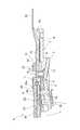
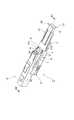
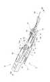
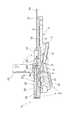
図1は、本発明に係る光ファイバ接続用治具の一実施形態を示す斜視図である。図2は、図1に示した光ファイバ接続用治具の平面図であり、図3は、その側面図である。また、図4は、図1におけるIV−IV線断面図である。 FIG. 1 is a perspective view showing an embodiment of an optical fiber connecting jig according to the present invention. 2 is a plan view of the optical fiber connecting jig shown in FIG. 1, and FIG. 3 is a side view thereof. 4 is a cross-sectional view taken along line IV-IV in FIG.
図1〜図4に示す光ファイバ接続用治具1は、メカニカルスプライス型の光コネクタに光ファイバを接続する際に利用する治具である。図1においては、光コネクタとして、素線把持型の光コネクタプラグAを例示している。この光コネクタプラグAは、メカニカルスプライス20を内蔵しており、メカニカルスプライス20の先端部分には、短尺光ファイバ23が挿入されたフェルール24が保持されている(図7参照)。 The optical
図1〜図4に示すように、光ファイバ接続用治具1は、略直方体形状のベース2と、回動アーム3とを備えている。ベース2は、例えばPOM(ポリオキシメチレン)、PPE(ポリフェニレンエーテル)といった可撓性を有する合成樹脂によって一体成型されている。或いは、ベース2は、PC(ポリカーボネイト)といった汎用合成樹脂により一体成型される。ベース2の先端側の左右には、下方に延在する略長方形状の側板部4,4がそれぞれ形成されており、この側板部4,4の一部には、作業者が光ファイバ接続用治具1を保持しやすいように滑り止め加工が施されている。ベース2の先端側には、上下に貫通する断面矩形の楔挿通開口部5がベース2の長手方向に沿って形成されている。また、ベース2の後端側の底面には、後述する第2の操作部17の押下量を規制するための断面台形状の規制部6(図3参照)が形成されている。 As shown in FIGS. 1 to 4, the optical
このベース2の上面には、先端側から順に、光コネクタプラグAが載置されるコネクタ載置部7と、素線ホルダ31に保持された光ファイバ素線30を案内するファイバガイド部8とが設けられている。また、コネクタ載置部7とファイバガイド部8との間には、光ファイバ素線30の先端側を位置決めする位置決め用ガイド部9が設けられている。 On the upper surface of the
コネクタ載置部7は、ベース2上面の両縁部に沿って延在する一対のコネクタ保持壁10,10と、コネクタ保持壁10,10よりも中央側の両縁部に形成された一対のコネクタ位置決め壁11,11とを有している。このコネクタ保持壁10,10及びコネクタ位置決め壁11,11の協働により、コネクタ載置部7に載置される光コネクタプラグAは、内蔵するメカニカルスプライス20の楔挿入口20a(図7参照)と、楔挿通開口部5との位置を合わせた状態でしっかりと保持される。また、コネクタ位置決め壁11,11の背面には、環状の引掛部11a,11aがそれぞれ形成されている。この引掛部11aは、光コネクタプラグAと素線ホルダ31との仮固定に用いられる。 The
ファイバガイド部8は、ベース2上面の略中央で長手方向に延在するレール12と、レール12の端部に設けられたホルダ位置決め壁13とを有している。ホルダ位置決め壁13は、素線ホルダ31がファイバガイド部8に載置される際の初期位置を規定している。また、レール12は、初期位置に載置された素線ホルダ31をコネクタ載置部7に向けてスライド可能に案内する。 The
位置決め用ガイド部9は、コネクタ位置決め壁11,11の間に位置しており、位置決め用ガイド部9の上面側には、断面U字状の溝部14が形成されている。この位置決め用ガイド部9により、ファイバガイド部8によって案内される光ファイバ素線30の先端側は、光コネクタプラグA内のメカニカルスプライス20に対して大まかに位置決めされる。また、位置決め用ガイド部9は、ベース2を成型する合成樹脂の可撓性により変形容易となっており、上方から一定の押圧力を加えることで下方に潰れ、ベース2上から退避するようになっている。 The
回動アーム3は、ベース2の底面側に配置され、ベース2の長手方向と直交するように側板部4,4の後端側に設けられた回動軸Xを中心として回動自在となっている。回動アーム3の先端側は、図4に示すように、回動軸Xからベース2の先端側に延在しており、回動アーム3の先端側の上面には、前後一対の楔15,15が設けられている。また、回動アーム3の後端側は、回動軸Xを挟んでベース2の後端側まで延在している。 The
回動アーム3の先端側の底面には、この回動アーム3の先端側をコネクタ載置部7に近づける向きに手動で回動させる第1の操作部16が設けられている。この第1の操作部16を押下することにより、楔15,15が楔挿通開口部5を通してコネクタ載置部7に進出し、光コネクタプラグAのメカニカルスプライス20の下部に設けられた楔挿入口20aに挿入される。これにより、図5(a)に示すように、メカニカルスプライス20内の一対の保持部材21,21が付勢部材22の付勢力に抗して離間し、メカニカルスプライス20のファイバ挿入空間Sが開状態(すなわち、光ファイバを挿入可能な状態)となる。 On the bottom surface on the distal end side of the
一方、回動アーム3の後端側の底面には、回動アーム3の先端側をコネクタ載置部7から遠ざける向きに手動で回動される第2の操作部17が設けられている。この第2の操作部17を規制部6に当接する位置まで押下することより、楔15,15が楔挿入口20aを通ってコネクタ載置部7から退避し、楔挿入口20aから抜脱される。これにより、図5(b)に示すように、メカニカルスプライス20内の一対の保持部材21,21が付勢部材22の付勢力に従って突き合わされ、ファイバ挿入空間Sが閉状態(すなわち、光ファイバを挿入不可能な状態)となる。 On the other hand, on the bottom surface on the rear end side of the
なお、図1及び図4に示すように、第1の操作部16及び第2の操作部17のそれぞれにも、作業者が押下しやすいように滑り止め加工が施されている。 As shown in FIGS. 1 and 4, each of the
次に、上述した構成を有する光ファイバ接続用治具1を用いて光ファイバを光コネクタに接続する接続手順について説明する。 Next, a connection procedure for connecting an optical fiber to an optical connector using the optical
まず、図6及び図7に示すように、光コネクタプラグAをコネクタ載置部7に載置する。この状態で、第1の操作部16を押下すると、楔15,15がメカニカルスプライス20の楔挿入口20aに挿入され、ファイバ挿入空間Sが開状態となる。 First, as shown in FIGS. 6 and 7, the optical connector plug A is placed on the
次に、図8及び図9に示すように、ファイバガイド部8に光ファイバ素線30を保持した素線ホルダ31を載置する。この素線ホルダ31は、光ファイバ素線30の先端側が載置される素線載置部32と、光ファイバ素線30の先端側を素線載置部32に押さえ付けて保持する素線押さえ部33とを備えている。また、素線載置部32の両側面には、引掛部11a,11aに対応する突起部32a,32aが形成されている。素線載置部32の先端側から突出する光ファイバ素線30の先端部分には端末処理が施されており、所定長さの光ファイバ34が露出している。 Next, as shown in FIGS. 8 and 9, the
この素線ホルダ31をファイバガイド部8に載置する際、まず素線載置部32の背面側をホルダ位置決め壁13の前面側に当接させるようにして、素線ホルダ31をレール12上に載置する。このとき、光ファイバ34の先端側は、位置決め用ガイド部9の溝部14に載置され、メカニカルスプライス20に対して大まかに位置決めされる。そして、素線ホルダ31をファイバガイド部8のレール12に沿って光コネクタプラグA側にスライドさせると、光ファイバ34がメカニカルスプライス20のファイバ挿入空間S内に挿入され、光ファイバ34の先端と、メカニカルスプライス20内の短尺光ファイバ23の後端とが突き合わされる。 When placing the
なお、素線ホルダ31の光コネクタプラグA側へのスライド量は、素線載置部2の前面側が位置決め用ガイド部27に当接する位置で規制される。また、この位置において、引掛部11aが突起部32aに掛け止められ、素線ホルダ31と光コネクタプラグAとが仮固定される。 Note that the sliding amount of the
この後、第2の操作部17を規制部6に当接する位置まで押下すると、図10及び図11に示すように、楔15,15がメカニカルスプライス20の楔挿入口20aから脱抜され、ファイバ挿入空間Sが閉状態となる。これにより、光ファイバ34と短尺光ファイバ23との突き合わせ部分が固定される。最後に、光ファイバ接続用治具1を光コネクタプラグAから取り外し、光ファイバ素線30から素線ホルダ31を取り外すと、図12に示すように、光コネクタプラグAへの光ファイバ素線30の接続が完了する。 Thereafter, when the
以上説明したように、光ファイバ接続用治具1では、ベース2の上面側に光コネクタプラグAを載置するコネクタ載置部7が設けられており、ベース2の底面側に、楔15,15をメカニカルスプライス20から抜脱するための第2の操作部17が位置している。このような構成により、作業者は、接続する光ファイバ34をメカニカルスプライス20内に挿入した後、光ファイバ接続用治具1を把持している手で第2の操作部17を操作することが可能となっている。これにより、片手で容易に光ファイバ接続用治具1の保持と楔15,15の抜脱操作とを行うことができ、敷設現場において作業者の熟練性が要求されることなく、光コネクタプラグAへの光ファイバ素線30の接続を行うことができる。 As described above, in the optical
また、光ファイバ接続用治具1では、第2の操作部17は、回動アーム3の回動軸Xを挟んでベース2の後端側におけるファイバガイド部8の反対側に延在する回動アーム3の他端側に設けられている。これにより、第2の操作部17を押下する際に、回動軸Xを支点とする梃子の原理の作用により、片手でも容易にメカニカルスプライス20から楔15,15を脱抜できる。 Further, in the optical
また、コネクタ載置部7とファイバガイド部8との間には、位置決め用ガイド部9が設けられている。このため、光ファイバ34をメカニカルスプライス20に挿入するにあたり、光ファイバ34の先端側を大まかに位置決めできるので、端末処理した光ファイバ34の先端が光コネクタプラグAや光ファイバ接続用治具1に当たることを抑止できる。 Further, a
さらに、光ファイバ接続用治具1では、コネクタ載置部7、ファイバガイド部8、及び位置決め用ガイド部9は、POM等の可撓性を有する樹脂材料によって一体成型されているので(或いは、PC等の剛性の高い樹脂により一体成型されているので)、部品点数を削減でき、光ファイバ接続用治具1の製造コストの低減を実現できる。 Furthermore, in the optical
また、位置決め用ガイド部9が、前述した可撓性を有する樹脂材料によって形成されているため(或いは、PC等の剛性の高い樹脂により一体成型されているため)、位置決め用ガイド部9のベース2上への配置・退避(或いは除去)を選択的に行うことが可能となる。したがって、光コネクタの種類によって位置決め用ガイド部9の要否が異なる場合でも、この光ファイバ接続用治具1を共通化して使用することができる。 In addition, since the
続いて、光ファイバ接続用治具1を用いて光ファイバを光コネクタに接続する接続手順の別の実施例について説明する。 Next, another embodiment of a connection procedure for connecting an optical fiber to an optical connector using the optical
この別の実施例では、光コネクタとして、素線把持型の光コネクタソケットBに光ファイバ素線30を接続する。この光コネクタソケットBは、光コネクタプラグAと対になる部材であり、光コネクタプラグAと同様に、メカニカルスプライス20を内蔵し、メカニカルスプライス20の先端部分には、短尺光ファイバ23が挿入されたフェルール24が保持されている(図14参照)。 In this another embodiment, the
この場合、図13及び図14に示すように、まず光コネクタソケットBをコネクタ載置部7に載置する。そして、第1の操作部16を押下し、ファイバ挿入空間Sを開状態とする。次に、図15及び図16に示すように、ファイバガイド部8に光ファイバ素線30を保持した素線ホルダ31を載置する。そして、素線ホルダ31を光コネクタソケットB側にスライドさせ、素線ホルダ31から突出する光ファイバ34をファイバ挿入空間S内に挿入し、光ファイバ34の先端と短尺光ファイバ23の後端とを突き合わせる。 In this case, as shown in FIGS. 13 and 14, the optical connector socket B is first placed on the
この後、図17及び図18に示すように、第2の操作部17を押下し、ファイバ挿入空間Sを閉状態とする。最後に、光ファイバ接続用治具1を光コネクタソケットBから取り外し、光ファイバ素線30から素線ホルダ31を取り外すと、図19に示すように、光コネクタソケットBへの光ファイバ素線30の接続が完了する。 Thereafter, as shown in FIGS. 17 and 18, the
このように、光ファイバ用接続治具1では、光コネクタソケットBについても共通の接続手順で光ファイバ素線30の接続を行うことができる。この接続にあたっては、上述した実施形態と同様の作用効果により、片手で容易に光ファイバ接続用治具1の保持と楔15,15の抜脱操作とを行うことができ、敷設現場において作業者の熟練性が要求されることなく、光コネクタソケットBへの光ファイバ素線30の接続を行うことができる。 Thus, in the optical
続いて、光ファイバ接続用治具1を用いて光ファイバを光コネクタに接続する接続手順の更に別の実施例について説明する。 Next, still another embodiment of a connection procedure for connecting an optical fiber to an optical connector using the optical
この更に別の実施例では、光コネクタとして、コード把持型の光コネクタプラグCに光ファイバコード40を接続する。この光コネクタプラグCも、メカニカルスプライス20を内蔵し、メカニカルスプライス20の先端部分には、短尺光ファイバ23が挿入されたフェルール24が保持されている(図21参照)。また、メカニカルスプライス20の後端側には、光ファイバ34(図22参照)をメカニカルスプライス20に対して位置決めする断面U字状の位置決め部材50が設けられている。さらに、光コネクタプラグCの後端側には、位置決め部材50を覆うための開閉自在のキャップ51が取り付けられている。 In still another embodiment, the
この場合、図20及び図21に示すように、まず光コネクタプラグCをコネクタ載置部7に載置する。このとき、光ファイバ接続用治具1の位置決め用ガイド部9は、光コネクタプラグCの後端側が載置されることによって下方に潰れ、ベース2上から退避する。 In this case, as shown in FIGS. 20 and 21, the optical connector plug C is first placed on the
次に、第1の操作部16を押下して、ファイバ挿入空間Sを開状態とし、さらに、図22及び図23に示すように、ファイバガイド部8に光ファイバコード40の先端側を保持したコードホルダ41を載置する。そして、コードホルダ41を光コネクタプラグC側にスライドさせ、コードホルダ41から突出する光ファイバ42をファイバ挿入空間S内に挿入し、光ファイバ42の先端と短尺光ファイバ23の後端とを突き合わせる。 Next, the
この後、図24及び図25に示すように、第2の操作部17を押下し、ファイバ挿入空間Sを閉状態とする。最後に、光ファイバ接続用治具1を光コネクタプラグCから取り外し、光コネクタプラグCのキャップ51を閉じると、図26に示すように、光コネクタプラグCへの光ファイバコード40の接続が完了する。 Thereafter, as shown in FIGS. 24 and 25, the
このように、光ファイバ接続用治具1では、コード把持型の光コネクタプラグCについても共通の接続手順で光ファイバコード40の接続を行うことができる。この接続にあたっても、上述した実施形態と同様の作用効果により、片手で容易に光ファイバ接続用治具1の保持と楔15,15の抜脱操作とを行うことができ、敷設現場において作業者の熟練性が要求されることなく、光コネクタプラグCへの光ファイバコード40の接続を行うことができる。 As described above, in the optical
1…光ファイバ接続用治具、2…ベース、3…回動アーム、7…コネクタ載置部、8…ファイバガイド部、9…位置決め用ガイド部、15…楔、17…第2の操作部(操作部)、20…メカニカルスプライス、34,42…光ファイバ、A,C…光コネクタプラグ、B…光コネクタソケット、X…回動軸。 DESCRIPTION OF
Claims (5)
Translated fromJapanese前記光コネクタが載置されるコネクタ載置部、及び当該コネクタ載置部に向けて前記光ファイバを案内するファイバガイド部が一面側に設けられたベースと、
前記ベースの他面側に設けられた回動アームと、
前記回動アームの一端側に設けられ、前記コネクタ載置部に進出して前記メカニカルスプライスに挿入される楔と、
前記楔が前記メカニカルスプライスから抜脱されるように前記アームを回動させる操作部とを備え、
前記操作部は、前記ベースの他面側において、前記ファイバガイド部の反対側に位置していることを特徴とする光ファイバ接続用治具。An optical fiber connecting jig used for connecting an optical fiber to an optical connector incorporating a mechanical splice,
A connector mounting portion on which the optical connector is mounted, and a base provided on one surface side with a fiber guide portion for guiding the optical fiber toward the connector mounting portion;
A pivot arm provided on the other side of the base;
A wedge provided on one end side of the pivot arm, advanced to the connector mounting portion and inserted into the mechanical splice;
An operating portion for rotating the arm so that the wedge is removed from the mechanical splice;
The operation part is located on the other side of the base on the opposite side of the fiber guide part.
前記操作部は、前記回動アームの他端側に設けられていることを特徴とする請求項1記載の光ファイバ接続用治具。The other end side of the rotation arm extends to the opposite side of the fiber guide portion with the rotation axis of the rotation arm interposed therebetween,
The optical fiber connection jig according to claim 1, wherein the operation portion is provided on the other end side of the rotating arm.
Priority Applications (1)
| Application Number | Priority Date | Filing Date | Title |
|---|---|---|---|
| JP2005316796AJP4537935B2 (en) | 2005-10-31 | 2005-10-31 | Optical fiber connection jig |
Applications Claiming Priority (1)
| Application Number | Priority Date | Filing Date | Title |
|---|---|---|---|
| JP2005316796AJP4537935B2 (en) | 2005-10-31 | 2005-10-31 | Optical fiber connection jig |
Publications (2)
| Publication Number | Publication Date |
|---|---|
| JP2007121886Atrue JP2007121886A (en) | 2007-05-17 |
| JP4537935B2 JP4537935B2 (en) | 2010-09-08 |
Family
ID=38145772
Family Applications (1)
| Application Number | Title | Priority Date | Filing Date |
|---|---|---|---|
| JP2005316796AActiveJP4537935B2 (en) | 2005-10-31 | 2005-10-31 | Optical fiber connection jig |
Country Status (1)
| Country | Link |
|---|---|
| JP (1) | JP4537935B2 (en) |
Cited By (19)
| Publication number | Priority date | Publication date | Assignee | Title |
|---|---|---|---|---|
| JP2007121888A (en)* | 2005-10-31 | 2007-05-17 | Sumitomo Electric Ind Ltd | Wire holder and optical fiber connection method |
| JP2007163763A (en)* | 2005-12-13 | 2007-06-28 | Hitachi Cable Ltd | Connection jig for optical connectors |
| JP2009139839A (en)* | 2007-12-10 | 2009-06-25 | Furukawa Electric Co Ltd:The | Optical connector |
| WO2009136583A1 (en)* | 2008-05-09 | 2009-11-12 | 住友電気工業株式会社 | Optical connector assembling jig and optical connector assembling method |
| WO2010016451A1 (en) | 2008-08-04 | 2010-02-11 | 住友電気工業株式会社 | Jig for optical connector |
| WO2011040276A1 (en)* | 2009-10-02 | 2011-04-07 | 住友電気工業株式会社 | Method for connecting optical fibers |
| WO2013022071A1 (en)* | 2011-08-09 | 2013-02-14 | 株式会社フジクラ | Mechanical splice unit, connection tool for mechanical splice, and optical fiber connection method |
| JP2013037231A (en)* | 2011-08-09 | 2013-02-21 | Fujikura Ltd | Connecting tool for mechanical splice and connecting method for optical fiber |
| JP2013037233A (en)* | 2011-08-09 | 2013-02-21 | Fujikura Ltd | Connecting tool for mechanical splice, connecting method for optical fiber, and attachment |
| WO2013035872A1 (en)* | 2011-09-08 | 2013-03-14 | 株式会社フジクラ | Optical fiber connection unit, optical fiber connection method, and optical fiber connection unit holding member |
| JP6078667B1 (en)* | 2016-02-10 | 2017-02-08 | 株式会社フジクラ | Optical connector manufacturing method and tool |
| US10561353B2 (en) | 2016-06-01 | 2020-02-18 | Glysens Incorporated | Biocompatible implantable sensor apparatus and methods |
| US10561351B2 (en) | 2011-07-26 | 2020-02-18 | Glysens Incorporated | Tissue implantable sensor with hermetically sealed housing |
| US10638962B2 (en) | 2016-06-29 | 2020-05-05 | Glysens Incorporated | Bio-adaptable implantable sensor apparatus and methods |
| US10660550B2 (en) | 2015-12-29 | 2020-05-26 | Glysens Incorporated | Implantable sensor apparatus and methods |
| US11255839B2 (en) | 2018-01-04 | 2022-02-22 | Glysens Incorporated | Apparatus and methods for analyte sensor mismatch correction |
| US11278668B2 (en) | 2017-12-22 | 2022-03-22 | Glysens Incorporated | Analyte sensor and medicant delivery data evaluation and error reduction apparatus and methods |
| KR20230060508A (en) | 2020-09-04 | 2023-05-04 | 니혼 츠신 덴자이 리미티드 | Optical fiber connection jigs and optical connectors |
| WO2025100084A1 (en)* | 2023-11-10 | 2025-05-15 | 株式会社フジクラ | Optical fiber processing tool |
Citations (7)
| Publication number | Priority date | Publication date | Assignee | Title |
|---|---|---|---|---|
| JPH10123347A (en)* | 1996-10-16 | 1998-05-15 | Furukawa Electric Co Ltd:The | Optical fiber mechanical splice apparatus and work tool for connecting the optical fiber |
| JP2000056175A (en)* | 1998-08-07 | 2000-02-25 | Fujikura Ltd | Optical connector connection tool |
| JP2000147316A (en)* | 1998-11-17 | 2000-05-26 | Hitachi Cable Ltd | Optical fiber butt connection tool |
| JP2005134585A (en)* | 2003-10-29 | 2005-05-26 | Fujikura Ltd | Optical fiber splicing tool |
| JP2005250294A (en)* | 2004-03-05 | 2005-09-15 | Chugoku Electric Power Co Inc:The | Member and method for reinforcing optical fiber connection part |
| JP2005283954A (en)* | 2004-03-30 | 2005-10-13 | Fujikura Ltd | Optical connector, optical connector assembly method |
| JP2006285149A (en)* | 2005-04-05 | 2006-10-19 | Sumitomo Electric Ind Ltd | Optical fiber connecting jig and optical connector with the jig |
- 2005
- 2005-10-31JPJP2005316796Apatent/JP4537935B2/enactiveActive
Patent Citations (7)
| Publication number | Priority date | Publication date | Assignee | Title |
|---|---|---|---|---|
| JPH10123347A (en)* | 1996-10-16 | 1998-05-15 | Furukawa Electric Co Ltd:The | Optical fiber mechanical splice apparatus and work tool for connecting the optical fiber |
| JP2000056175A (en)* | 1998-08-07 | 2000-02-25 | Fujikura Ltd | Optical connector connection tool |
| JP2000147316A (en)* | 1998-11-17 | 2000-05-26 | Hitachi Cable Ltd | Optical fiber butt connection tool |
| JP2005134585A (en)* | 2003-10-29 | 2005-05-26 | Fujikura Ltd | Optical fiber splicing tool |
| JP2005250294A (en)* | 2004-03-05 | 2005-09-15 | Chugoku Electric Power Co Inc:The | Member and method for reinforcing optical fiber connection part |
| JP2005283954A (en)* | 2004-03-30 | 2005-10-13 | Fujikura Ltd | Optical connector, optical connector assembly method |
| JP2006285149A (en)* | 2005-04-05 | 2006-10-19 | Sumitomo Electric Ind Ltd | Optical fiber connecting jig and optical connector with the jig |
Cited By (33)
| Publication number | Priority date | Publication date | Assignee | Title |
|---|---|---|---|---|
| JP2007121888A (en)* | 2005-10-31 | 2007-05-17 | Sumitomo Electric Ind Ltd | Wire holder and optical fiber connection method |
| JP2007163763A (en)* | 2005-12-13 | 2007-06-28 | Hitachi Cable Ltd | Connection jig for optical connectors |
| JP2009139839A (en)* | 2007-12-10 | 2009-06-25 | Furukawa Electric Co Ltd:The | Optical connector |
| US8401356B2 (en) | 2008-05-09 | 2013-03-19 | Sumitomo Electric Industries, Ltd. | Optical connector assembling jig and optical connector assembling method |
| WO2009136583A1 (en)* | 2008-05-09 | 2009-11-12 | 住友電気工業株式会社 | Optical connector assembling jig and optical connector assembling method |
| JP2009271431A (en)* | 2008-05-09 | 2009-11-19 | Sumitomo Electric Ind Ltd | Optical connector assembling tool and optical connector assembling method |
| WO2010016451A1 (en) | 2008-08-04 | 2010-02-11 | 住友電気工業株式会社 | Jig for optical connector |
| CN102099719A (en)* | 2008-08-04 | 2011-06-15 | 住友电气工业株式会社 | Jig for optical connector |
| US9075204B2 (en) | 2008-08-04 | 2015-07-07 | Sumitomo Electric Industries, Ltd. | Optical connector construction tool |
| KR20110040880A (en) | 2008-08-04 | 2011-04-20 | 스미토모 덴키 고교 가부시키가이샤 | Jig for Optical Connector |
| WO2011040276A1 (en)* | 2009-10-02 | 2011-04-07 | 住友電気工業株式会社 | Method for connecting optical fibers |
| JP2011081038A (en)* | 2009-10-02 | 2011-04-21 | Sumitomo Electric Ind Ltd | Method for connecting optical fibers |
| CN102576126A (en)* | 2009-10-02 | 2012-07-11 | 住友电气工业株式会社 | Fiber connection method |
| US8763246B2 (en) | 2009-10-02 | 2014-07-01 | Sumitomo Electric Industries, Ltd. | Method for connecting optical fibers |
| US10561351B2 (en) | 2011-07-26 | 2020-02-18 | Glysens Incorporated | Tissue implantable sensor with hermetically sealed housing |
| JP2013037233A (en)* | 2011-08-09 | 2013-02-21 | Fujikura Ltd | Connecting tool for mechanical splice, connecting method for optical fiber, and attachment |
| US9541706B2 (en) | 2011-08-09 | 2017-01-10 | Fujikura Ltd. | Mechanical splice unit, mechanical splicing tool, and optical fiber splicing method |
| JP2013037231A (en)* | 2011-08-09 | 2013-02-21 | Fujikura Ltd | Connecting tool for mechanical splice and connecting method for optical fiber |
| WO2013022071A1 (en)* | 2011-08-09 | 2013-02-14 | 株式会社フジクラ | Mechanical splice unit, connection tool for mechanical splice, and optical fiber connection method |
| US10025037B2 (en) | 2011-08-09 | 2018-07-17 | Fujikura Ltd. | Method of splicing optical fiber and optical fiber splicing device |
| CN103858036A (en)* | 2011-09-08 | 2014-06-11 | 株式会社藤仓 | Optical fiber connection unit, optical fiber connection method, and optical fiber connection unit holding member |
| CN103858036B (en)* | 2011-09-08 | 2017-01-11 | 株式会社藤仓 | Optical fiber connection unit, optical fiber connection method, and optical fiber connection unit holding member |
| US9494743B2 (en) | 2011-09-08 | 2016-11-15 | Fujikura Ltd. | Optical fiber splicing unit, optical fiber splicing method, and holding member for optical fiber splicing unit |
| WO2013035872A1 (en)* | 2011-09-08 | 2013-03-14 | 株式会社フジクラ | Optical fiber connection unit, optical fiber connection method, and optical fiber connection unit holding member |
| US10736553B2 (en) | 2012-07-26 | 2020-08-11 | Glysens Incorporated | Method of manufacturing an analyte detector element |
| US10660550B2 (en) | 2015-12-29 | 2020-05-26 | Glysens Incorporated | Implantable sensor apparatus and methods |
| JP6078667B1 (en)* | 2016-02-10 | 2017-02-08 | 株式会社フジクラ | Optical connector manufacturing method and tool |
| US10561353B2 (en) | 2016-06-01 | 2020-02-18 | Glysens Incorporated | Biocompatible implantable sensor apparatus and methods |
| US10638962B2 (en) | 2016-06-29 | 2020-05-05 | Glysens Incorporated | Bio-adaptable implantable sensor apparatus and methods |
| US11278668B2 (en) | 2017-12-22 | 2022-03-22 | Glysens Incorporated | Analyte sensor and medicant delivery data evaluation and error reduction apparatus and methods |
| US11255839B2 (en) | 2018-01-04 | 2022-02-22 | Glysens Incorporated | Apparatus and methods for analyte sensor mismatch correction |
| KR20230060508A (en) | 2020-09-04 | 2023-05-04 | 니혼 츠신 덴자이 리미티드 | Optical fiber connection jigs and optical connectors |
| WO2025100084A1 (en)* | 2023-11-10 | 2025-05-15 | 株式会社フジクラ | Optical fiber processing tool |
Also Published As
| Publication number | Publication date |
|---|---|
| JP4537935B2 (en) | 2010-09-08 |
Similar Documents
| Publication | Publication Date | Title |
|---|---|---|
| JP4537935B2 (en) | Optical fiber connection jig | |
| JP4665030B2 (en) | T5 terminal mounting tool | |
| US7103968B2 (en) | Cable terminating apparatus | |
| JP4476015B2 (en) | Optical fiber connector removal tool | |
| EP0871270A2 (en) | Hand tool | |
| US6872090B2 (en) | Cable terminating apparatus and method | |
| JPH0789509B2 (en) | Tongs for finishing conductor ends | |
| JP4832389B2 (en) | Optical connector assembly jig | |
| JP3851839B2 (en) | Connector release structure and connector release jig | |
| JP4631513B2 (en) | Optical fiber connecting jig and optical connector with the jig | |
| JP4634280B2 (en) | Wire holder and optical fiber connection method | |
| JP2006178289A (en) | Optical fiber holder and optical fiber cable processing method | |
| JP2008262245A (en) | Optical connector assembly tool | |
| JP4198129B2 (en) | Cable connector insertion / extraction tool | |
| JP5027012B2 (en) | Optical cable connection structure | |
| US20100021110A1 (en) | Mechanical splice` | |
| JPH1130727A (en) | Optical fiber holder | |
| JP4303713B2 (en) | Optical fiber core holding member and optical connector connection method | |
| JP2011059137A (en) | Mounting auxiliary device for optical connector and optical connector | |
| JP2004233403A (en) | Connector and its attachment / detachment tool | |
| JP3995250B2 (en) | Centering and cutting mechanism | |
| RU2835722C1 (en) | Hand-held crimping tongs | |
| JP5719796B2 (en) | Optical fiber connection tool and optical fiber connection method | |
| JP4177306B2 (en) | Optical fiber fixing jig | |
| JP2009087571A (en) | Lever connector |
Legal Events
| Date | Code | Title | Description |
|---|---|---|---|
| A621 | Written request for application examination | Free format text:JAPANESE INTERMEDIATE CODE: A621 Effective date:20080515 | |
| A977 | Report on retrieval | Free format text:JAPANESE INTERMEDIATE CODE: A971007 Effective date:20100127 | |
| A131 | Notification of reasons for refusal | Free format text:JAPANESE INTERMEDIATE CODE: A131 Effective date:20100316 | |
| A521 | Request for written amendment filed | Free format text:JAPANESE INTERMEDIATE CODE: A523 Effective date:20100511 | |
| TRDD | Decision of grant or rejection written | ||
| A01 | Written decision to grant a patent or to grant a registration (utility model) | Free format text:JAPANESE INTERMEDIATE CODE: A01 Effective date:20100615 | |
| A01 | Written decision to grant a patent or to grant a registration (utility model) | Free format text:JAPANESE INTERMEDIATE CODE: A01 | |
| A61 | First payment of annual fees (during grant procedure) | Free format text:JAPANESE INTERMEDIATE CODE: A61 Effective date:20100618 | |
| FPAY | Renewal fee payment (event date is renewal date of database) | Free format text:PAYMENT UNTIL: 20130625 Year of fee payment:3 | |
| R150 | Certificate of patent or registration of utility model | Ref document number:4537935 Country of ref document:JP Free format text:JAPANESE INTERMEDIATE CODE: R150 Free format text:JAPANESE INTERMEDIATE CODE: R150 | |
| S531 | Written request for registration of change of domicile | Free format text:JAPANESE INTERMEDIATE CODE: R313531 | |
| R350 | Written notification of registration of transfer | Free format text:JAPANESE INTERMEDIATE CODE: R350 | |
| R250 | Receipt of annual fees | Free format text:JAPANESE INTERMEDIATE CODE: R250 | |
| R250 | Receipt of annual fees | Free format text:JAPANESE INTERMEDIATE CODE: R250 | |
| R250 | Receipt of annual fees | Free format text:JAPANESE INTERMEDIATE CODE: R250 | |
| R250 | Receipt of annual fees | Free format text:JAPANESE INTERMEDIATE CODE: R250 | |
| R250 | Receipt of annual fees | Free format text:JAPANESE INTERMEDIATE CODE: R250 | |
| R250 | Receipt of annual fees | Free format text:JAPANESE INTERMEDIATE CODE: R250 | |
| R250 | Receipt of annual fees | Free format text:JAPANESE INTERMEDIATE CODE: R250 | |
| R250 | Receipt of annual fees | Free format text:JAPANESE INTERMEDIATE CODE: R250 | |
| R250 | Receipt of annual fees | Free format text:JAPANESE INTERMEDIATE CODE: R250 | |
| R250 | Receipt of annual fees | Free format text:JAPANESE INTERMEDIATE CODE: R250 |