JP2007121499A - Differential interference observation method and microscope - Google Patents
Differential interference observation method and microscopeDownload PDFInfo
- Publication number
- JP2007121499A JP2007121499AJP2005311021AJP2005311021AJP2007121499AJP 2007121499 AJP2007121499 AJP 2007121499AJP 2005311021 AJP2005311021 AJP 2005311021AJP 2005311021 AJP2005311021 AJP 2005311021AJP 2007121499 AJP2007121499 AJP 2007121499A
- Authority
- JP
- Japan
- Prior art keywords
- differential interference
- objective lens
- light
- beam splitter
- disposed
- Prior art date
- Legal status (The legal status is an assumption and is not a legal conclusion. Google has not performed a legal analysis and makes no representation as to the accuracy of the status listed.)
- Withdrawn
Links
Images


Landscapes
- Microscoopes, Condenser (AREA)
Abstract
Translated fromJapaneseDescription
Translated fromJapanese本発明は、同軸落射照明光学系による微分干渉観察方法、及び同軸落射照明光学系を備えた顕微鏡に関する。 The present invention relates to a differential interference observation method using a coaxial epi-illumination optical system, and a microscope including the coaxial epi-illumination optical system.
顕微鏡の照明法の1つに、対物レンズを観察と照明との双方に利用する同軸落射照明法がある。この照明法では、対物レンズへ投光された照明光の一部が対物レンズの途中で反射し、フレアの発生する可能性があるので、フレア防止機能付きの同軸落射照明光学系が有効である(特許文献1など参照)。
この同軸落射照明光学系は、偏光を利用し、対物レンズの途中で反射した迷光と対物レンズの全体を往復した必要光とを分離するものである。これを利用するときには、迷光の偏光方向と必要光の偏光方向とに差異を与えるため、対物レンズの先端へ1/4波長板を装着する必要がある。One of the illumination methods of a microscope is a coaxial epi-illumination method that uses an objective lens for both observation and illumination. In this illumination method, a part of the illumination light projected onto the objective lens may be reflected in the middle of the objective lens and flare may occur, so a coaxial epi-illumination optical system with a flare prevention function is effective. (Refer
This coaxial epi-illumination optical system uses polarized light to separate stray light reflected in the middle of the objective lens and necessary light that reciprocates the entire objective lens. When this is used, in order to give a difference between the polarization direction of the stray light and the polarization direction of the necessary light, it is necessary to attach a quarter wavelength plate to the tip of the objective lens.
また、この照明光学系で微分干渉観察(特許文献2などを参照)を行う場合は、対物レンズの後側焦点近傍へ微分干渉プリズムを挿入すると共に、対物レンズ先端の1/4波長板をダミーガラスへ付け替えればよい。
しかしながら、この付け替えの作業は手間がかかるので、通常観察から微分干渉観察への切り替えは、あまり頻繁には行われない。
そこで本発明の目的は、フレア防止機能付きの同軸落射照明光学系を用いながら簡単に微分干渉観察を行うことのできる微分干渉観察方法及び顕微鏡を提供することにある。However, since this replacement work takes time, switching from normal observation to differential interference observation is not performed very frequently.
SUMMARY OF THE INVENTION An object of the present invention is to provide a differential interference observation method and a microscope capable of easily performing differential interference observation while using a coaxial epi-illumination optical system with a flare prevention function.
本発明の微分干渉観察方法は、光源から射出した光線をビームスプリッタ及び対物レンズを介して標本面へ導光すると共に、その標本面から射出した光線を、前記対物レンズ及び前記ビームスプリッタを介して前記標本面の像を観察するための観察手段へ導光する同軸落射照明光学系を用いた微分干渉観察方法であって、前記対物レンズの前記標本面の側に波長板を配置し、前記光源と前記ビームスプリッタとの間に偏光子を配置し、前記ビームスプリッタと前記観察手段との間に検光子を配置し、前記対物レンズの後側焦点面近傍に微分干渉プリズムを配置し、前記微分干渉プリズムにより光軸上で分離された互いに垂直な振動方向を有する2つの直線偏光に生じる位相差と、前記波長板が前記2つの直線偏光に与える位相差とを、等量反対符号に設定することを特徴とする。 The differential interference observation method of the present invention guides the light beam emitted from the light source to the sample surface via the beam splitter and the objective lens, and transmits the light beam emitted from the sample surface via the objective lens and the beam splitter. A differential interference observation method using a coaxial epi-illumination optical system that guides light to observation means for observing an image of the sample surface, wherein a wave plate is disposed on the sample surface side of the objective lens, and the light source A polarizer is disposed between the beam splitter and the beam splitter, an analyzer is disposed between the beam splitter and the observation means, a differential interference prism is disposed near the rear focal plane of the objective lens, and the differential The phase difference generated in two linearly polarized lights having vibration directions perpendicular to each other separated on the optical axis by the interference prism and the phase difference given to the two linearly polarized lights by the wave plate are equivalent to each other. And setting the sign.
なお、前記微分干渉プリズムにより分離された互いに垂直な振動方向を有する2つの直線偏光の光軸上の位相差が1/4波長であることが望ましい。
また、本発明の顕微鏡は、光源から射出した光線をビームスプリッタ及び対物レンズを介して標本面へ導光すると共に、その標本面から射出した光線を、前記対物レンズ及び前記ビームスプリッタを介して前記標本面の像を観察するための観察手段へ導光する同軸落射照明光学系を用いた顕微鏡であって、前記標本面の側に波長板を配置した前記対物レンズと、前記光源と前記ビームスプリッタとの間に配置される偏光子と、前記ビームスプリッタと前記観察手段との間に配置される検光子と、前記対物レンズの後側焦点面近傍に配置される微分干渉プリズムとを備え、前記微分干渉プリズムにより光軸上で分離された互いに垂直な振動方向を有する2つの直線偏光に生じる位相差と、前記波長板が前記2つの直線偏光に与える位相差とは、等量反対符号に設定されることを特徴とする。In addition, it is desirable that the phase difference on the optical axis of the two linearly polarized light having the vibration directions perpendicular to each other separated by the differential interference prism is ¼ wavelength.
The microscope of the present invention guides the light beam emitted from the light source to the sample surface via the beam splitter and the objective lens, and transmits the light beam emitted from the sample surface via the objective lens and the beam splitter. A microscope using a coaxial epi-illumination optical system for guiding light to an observation means for observing an image of a sample surface, the objective lens having a wave plate disposed on the sample surface side, the light source, and the beam splitter A polarizer disposed between, an analyzer disposed between the beam splitter and the observation means, and a differential interference prism disposed in the vicinity of a rear focal plane of the objective lens, The phase difference that occurs in two linearly polarized light having mutually perpendicular vibration directions separated on the optical axis by the differential interference prism, and the phase difference that the wavelength plate gives to the two linearly polarized light are: Characterized in that it is set to an amount opposite sign.
本発明によれば、フレア防止機能付きの同軸落射照明光学系を用いながら簡単に微分干渉観察を行うことのできる微分干渉観察方法及び顕微鏡が実現する。 ADVANTAGE OF THE INVENTION According to this invention, the differential interference observation method and microscope which can perform differential interference observation simply, using the coaxial epi-illumination optical system with a flare prevention function are implement | achieved.
本実施形態は、顕微鏡及びそれを用いた観察方法の実施形態である。
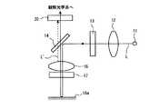
図1は、顕微鏡の構成を示す図である。
図1に示すとおり、本顕微鏡1には、微分干渉観察と通常観察とに適用できる光源11、集光レンズ12、偏光子13、ハーフミラー(ビームスプリッタ)14、ステージ19、検光子20、観察光学系21などが備えられる。顕微鏡1のレボルバには対物レンズ16が装着され、ステージ19には被観察物(標本)18が載置される。対物レンズ16は、例えば低倍率観察用(1倍〜2.5倍程度)の対物レンズである。The present embodiment is an embodiment of a microscope and an observation method using the microscope.
FIG. 1 is a diagram illustrating a configuration of a microscope.
As shown in FIG. 1, the
このうち、光源11、集光レンズ12、ハーフミラー14、対物レンズ16が、同軸落射照明光学系を構成している。このうち、ハーフミラー14よりも光源側の光路に偏光子13が配置され、ハーフミラー14よりも観察側の光路に検光子20が配置され、対物レンズ16の先端に1/4波長板17が装着されている。これらの偏光子13、検光子20、及び1/4波長板17が、フレア防止機能を果たす。 Among these, the
また、顕微鏡1には、対物レンズ16の後側焦点近傍に対し微分干渉プリズム15を挿脱するためのスライド機構が設けられている。この微分干渉プリズム15が離脱された状態では、同軸落射照明による通常観察が可能となり、微分干渉プリズム15が挿入された状態では、同軸落射照明による微分干渉観察が可能となる。因みに、本実施形態の微分干渉観察時には、1/4波長板17をダミーガラスへ付け替える必要は無い。 Further, the
なお、図1では、観察像を観察眼Eの網膜上へ結像するタイプの観察光学系21を示したが、観察像を撮像素子上へ結像するタイプの観察光学系を適用することも可能である。その場合、撮像素子は不図示のモニタへ接続され、ユーザはそのモニタ上で観察像を観察することになる。
先ず、本顕微鏡による通常観察を説明する。Although FIG. 1 shows an observation
First, normal observation with this microscope will be described.
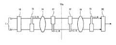
図2は、通常観察時に本顕微鏡に形成される光路を説明する図である。なお、図2では、対物レンズ16を単レンズで表した。
図2に示すとおり、光源11から射出した光Lは、集光レンズ12、偏光子13を順に通過した後、ハーフミラー14で反射し、像側から対物レンズ16へ入射する。その光Lは、対物レンズ16の物体側から射出し、1/4波長板17を介して標本面18aを照明する。その光Lは、標本面18aで反射することで観察像の情報を含んだ光となり、1/4波長板17、対物レンズ16を逆に進行した後、ハーフミラー14を通過し、検光子20へ入射する。FIG. 2 is a diagram for explaining an optical path formed in the microscope during normal observation. In FIG. 2, the
As shown in FIG. 2, the light L emitted from the
ここで、偏光子13の偏光軸、1/4波長板17の高速軸、検光子20の偏光軸の関係は、図3に示すとおりに設定されている。すなわち、偏光子13と検光子20とはクロスニコルの関係で配置されており、1/4波長板17の高速軸は、偏光子13及び検光子20の偏光軸から45°傾いている。
このとき、図2の偏光子13から射出する光Lは、偏光子13の偏光軸に沿った直線偏光となる。その光Lの多くは対物レンズ16を通過するが、光Lの一部は対物レンズ16の何れかのレンズ面で反射し、迷光L’となる。Here, the relationship between the polarization axis of the
At this time, the light L emitted from the
この迷光L’は、偏光子13の偏光軸に沿った直線偏光のまま、検光子20へ向かうが、検光子20の偏光軸はその迷光L’の偏光方向と90°の角度を成すので、迷光L’は検光子20を通過することはできずにカットされる。
一方、対物レンズ16を通過した光Lは、偏光子13の偏光軸に沿った直線偏光のまま1/4波長板17へ向かう。その1/4波長板17の高速軸は、その光Lの偏光方向と45°の角度を成すので、光Lのうち、高速軸方向の偏光成分と低速軸方向の偏光成分とには、1/4波長板17において1/4波長分の位相差が与えられる。よって、標本面18aは、円偏光の光Lで照明される。The stray light L ′ travels toward the
On the other hand, the light L that has passed through the
また、それらの2つの偏光成分には、1/4波長板17を再度通過することで、さらに1/4波長分の位相差が与えられる。よって、1/4波長板17を往復した後の2つの偏光成分には、トータルで1/2波長分の位相差が設けられる。よって、対物レンズ16に戻る光Lは、往復前の偏光方向(=偏光子13の偏光軸の方向)から90°ずれた方向(=検光子20の偏光軸の方向)の直線偏光となる。よって、この光Lは、検光子20を通過することができる。 Further, a phase difference corresponding to 1/4 wavelength is given to these two polarization components by passing through the 1/4
したがって、本実施形態の通常観察では、フレアの発生しない良好な観察像が形成される。
次に、本顕微鏡による微分干渉観察を説明する。
図4は、微分干渉観察時に本顕微鏡に形成される光路を説明する図である。なお、図4(a)では、光路を透過型で表した。標本面18aの左側が、標本面18aに入射するまでの光Lの光路であり、標本面18aの右側が、標本面18aで反射してからの光Lの光路である。なお、ハーフミラー14を省略し、わかりやすくするために微分干渉プリズム15のシア量を実際よりも大きく表した。Therefore, in the normal observation of this embodiment, a good observation image without flare is formed.
Next, differential interference observation with this microscope will be described.
FIG. 4 is a diagram illustrating an optical path formed in the microscope during differential interference observation. In FIG. 4A, the optical path is shown as a transmission type. The left side of the
図4(a)に示すように、微分干渉観察時であっても、1/4波長板17は光路に挿入されたままである。また、図4(b)に示すように、微分干渉プリズム15のシア方向は、偏光子13及び検光子20の偏光軸と45°の角度を成している。
図4の偏光子13から射出された直線偏光Lは、微分干渉プリズム15で偏光方向が互いに垂直である2つの偏光成分Lx、Lyに分離される。各偏光成分の偏光方向はLx:シア方向と垂直方向、Ly:シア方向と平行方向である。本実施形態の微分干渉プリズム15は、光軸上で前記微分干渉プリズム15によって分離された2つの直線偏光成分Lx,Lyの間に1/4波長分位相差が生じるように配置されている。2つの直線偏光成分Lx,Lyは、微分干渉プリズム15から互いに異なる方向へ進行し、対物レンズ16、1/4波長板17を経由して、わずかにずれた平行光として標本面18aに射出される。標本面18aで反射された偏光成分Lx,Lyは、1/4波長板17、対物レンズ16の互いにずれた位置を進行して微分干渉プリズム15へ戻る。この間、2つの偏光成分Lx,Lyは、対物レンズ16によって対物レンズ16の後側焦点面に集光され、微分干渉プリズム15において互いの光路を重ね合わせ1つの光Lに統合される。その光Lのうち、検光子20の偏光軸方向の成分が検光子20を通過し、観察像(ここでは微分干渉観察像)を形成する。As shown in FIG. 4A, the quarter-
The linearly polarized light L emitted from the
ここで、本実施形態の微分干渉プリズム15と光Lの光路との位置関係は、図5(a)に概念的に示すとおり、2つの偏光成分Lx,Lyに1/4波長分の位相差が生じるように最適化されている。
すなわち、本実施形態の微分干渉プリズム15は、光軸上で分離された2つの直線偏光Lx,Lyの位相差がプリズム通過後に1/4波長となるように設計されている。因みに本実施形態の微分干渉プリズム15によると、分離後の位相差が0となるのは、図5(b)に示すように、光軸からシア方向に平行にずれた位置で分離された2つの直線偏光Lx’,Ly’である。Here, the positional relationship between the
That is, the
そのため、例えば、本顕微鏡の微分干渉プリズム15を挿脱するスライド機構は、図5(a)の位置関係が達成された時点でスライドを停止させる位置決め機能を搭載しているとよい。或いは、微分干渉プリズム15の外形(保持枠の外形)が、図5(a)の位置関係が達成した時点でスライドを停止させるような形状に整えられていてもよい。
なお、各図では、微分干渉プリズム15がウォラストンプリズム(分離点がプリズム内部に存在するもの)であるかのごとく示したが、ノマルスキィプリズム(分離点がプリズム外部に存在するもの)であってもよい。何れの場合も、分離点が対物レンズ16の後側焦点と略一致する。Therefore, for example, the slide mechanism that inserts and removes the
In each figure, the
図6は、微分干渉プリズム15から偏光成分Ly,Lxに与えられる位相差の量を説明する概念図である。
図6に示すとおり、2つの偏光成分Ly,Lxには、微分干渉プリズム15を通過したときと、1/4波長板17を通過したときとの双方において位相差が与えられる。
1/4波長板17にて進相するのが偏光成分Lyであるときには、微分干渉プリズム15においてはその偏光成分Lyを遅相させればよい(つまり、微分干渉プリズム15においてもう一方の偏光成分Lxを進相させればよい。)。このとき、偏光子13から検光子20までの全光路(但し、標本面18aは除く)から2つの偏光成分Ly,Lxに与えられるトータルの位相差は、ゼロとなる。FIG. 6 is a conceptual diagram illustrating the amount of phase difference given from the
As shown in FIG. 6, the two polarization components Ly and Lx are given a phase difference both when they pass through the
When it is the polarization component Ly that is advanced by the
このため、仮に標本面18aが一様であれば、偏光子13から射出した光Lは、その偏光方向を変化させないまま、検光子20へ入射する。上述したとおり検光子20は偏光子13とクロスニコルの関係で配置されているので、その光Lは検光子20を通過することができず、微分干渉像は真っ黒となる。
一方、仮に標本面18aに段差が存在していれば、その段差に相当する光線にのみ、検光子20を通過できる偏光成分が含まれることになる。よって、微分干渉像上の段差部分のみが明るく表現される。For this reason, if the
On the other hand, if there is a step on the
したがって、本実施形態の微分干渉観察では、1/4波長板17が装着されたままであるにも拘わらず、良好な背景の微分干渉像を形成することが可能である。通常観察から微分干渉観察への切り替え時に、1/4波長板17を離脱させる手間も、それをダミーガラスに付け替える手間も生じない。
なお、本実施形態の微分干渉観察では、1/4波長板17を鋭敏色板として利用することも可能である。具体的には、2つの偏光成分のうち微分干渉プリズム15で進相させた成分を、前述とは逆に1/4波長板17でさらに進相させると、2つの偏光成分間の全位相差量が1波長となる。これにより、微分干渉像の背景を赤紫鋭敏色にすることができる。Therefore, in the differential interference observation of this embodiment, it is possible to form a good differential interference image of the background even though the quarter-
In the differential interference observation of this embodiment, the
また、本実施形態の顕微鏡には1/4波長板が用いられたが、1/4波長板の代わりに1/8波長板などの他の波長板を用いてもよい。何れの場合も、微分干渉プリズムから偏光成分Ly,Lxへ与えられる位相差を、波長板から2つの偏光成分Ly,Lxに与えられる位相差の等量反対符号に設定すればよい。 In addition, although the quarter wavelength plate is used in the microscope of the present embodiment, other wavelength plates such as a 1/8 wavelength plate may be used instead of the quarter wavelength plate. In any case, the phase difference given from the differential interference prism to the polarization components Ly and Lx may be set to the opposite sign of the equivalent phase difference given from the wave plate to the two polarization components Ly and Lx.
1…顕微鏡,11…光源,12…集光レンズ,13…偏光子,14…ハーフミラー,18…標本,19…ステージ,20…検光子,21…観察光学系,15…微分干渉プリズム,17…1/4波長板,16…対物レンズ DESCRIPTION OF
Claims (3)
Translated fromJapanese前記対物レンズの前記標本面の側に波長板を配置し、
前記光源と前記ビームスプリッタとの間に偏光子を配置し、
前記ビームスプリッタと前記観察手段との間に検光子を配置し、
前記対物レンズの後側焦点面近傍に微分干渉プリズムを配置し、
前記微分干渉プリズムにより光軸上で分離された互いに垂直な振動方向を有する2つの直線偏光に生じる位相差と、前記波長板が前記2つの直線偏光に与える位相差とを、等量反対符号に設定する
ことを特徴とする微分干渉観察方法。In order to guide the light beam emitted from the light source to the specimen surface via the beam splitter and the objective lens, and to observe the image of the specimen surface via the objective lens and the beam splitter. A differential interference observation method using a coaxial epi-illumination optical system that guides light to the observation means,
A wave plate is disposed on the sample surface side of the objective lens;
A polarizer is disposed between the light source and the beam splitter;
Placing an analyzer between the beam splitter and the observation means;
A differential interference prism is disposed in the vicinity of the rear focal plane of the objective lens,
The phase difference generated in the two linearly polarized lights having the vibration directions perpendicular to each other separated on the optical axis by the differential interference prism and the phase difference given to the two linearly polarized lights by the wavelength plate are equal in opposite sign. A differential interference observation method characterized by setting.
前記微分干渉プリズムにより分離された互いに垂直な振動方向を有する2つの直線偏光の光軸上の位相差が1/4波長である
ことを特徴とする微分干渉観察方法。The differential interference observation method according to claim 1,
A differential interference observation method, wherein a phase difference on an optical axis of two linearly polarized light beams having vibration directions perpendicular to each other separated by the differential interference prism is ¼ wavelength.
前記標本面の側に波長板を配置した前記対物レンズと、
前記光源と前記ビームスプリッタとの間に配置される偏光子と、
前記ビームスプリッタと前記観察手段との間に配置される検光子と、
前記対物レンズの後側焦点面近傍に配置される微分干渉プリズムとを備え、
前記微分干渉プリズムにより光軸上で分離された互いに垂直な振動方向を有する2つの直線偏光に生じる位相差と、前記波長板が前記2つの直線偏光に与える位相差とは、等量反対符号に設定される
ことを特徴とする顕微鏡。In order to guide the light beam emitted from the light source to the specimen surface via the beam splitter and the objective lens, and to observe the image of the specimen surface via the objective lens and the beam splitter. A microscope using a coaxial epi-illumination optical system for guiding light to the observation means,
The objective lens having a wave plate disposed on the sample surface side;
A polarizer disposed between the light source and the beam splitter;
An analyzer disposed between the beam splitter and the observation means;
A differential interference prism disposed in the vicinity of the rear focal plane of the objective lens,
The phase difference generated in the two linearly polarized lights having the vibration directions perpendicular to each other separated on the optical axis by the differential interference prism and the phase difference given to the two linearly polarized lights by the wavelength plate are equal in opposite sign. A microscope characterized by being set.
Priority Applications (1)
| Application Number | Priority Date | Filing Date | Title |
|---|---|---|---|
| JP2005311021AJP2007121499A (en) | 2005-10-26 | 2005-10-26 | Differential interference observation method and microscope |
Applications Claiming Priority (1)
| Application Number | Priority Date | Filing Date | Title |
|---|---|---|---|
| JP2005311021AJP2007121499A (en) | 2005-10-26 | 2005-10-26 | Differential interference observation method and microscope |
Publications (1)
| Publication Number | Publication Date |
|---|---|
| JP2007121499Atrue JP2007121499A (en) | 2007-05-17 |
Family
ID=38145429
Family Applications (1)
| Application Number | Title | Priority Date | Filing Date |
|---|---|---|---|
| JP2005311021AWithdrawnJP2007121499A (en) | 2005-10-26 | 2005-10-26 | Differential interference observation method and microscope |
Country Status (1)
| Country | Link |
|---|---|
| JP (1) | JP2007121499A (en) |
Cited By (10)
| Publication number | Priority date | Publication date | Assignee | Title |
|---|---|---|---|---|
| WO2008090636A1 (en) | 2007-01-26 | 2008-07-31 | Canon Kabushiki Kaisha | Process for manufacturing electrophotographic photoreceptor |
| WO2009064670A3 (en)* | 2007-11-13 | 2009-07-02 | Zygo Corp | Interferometer utilizing polarization scanning |
| US7978338B2 (en) | 2008-11-26 | 2011-07-12 | Zygo Corporation | Compound reference interferometer |
| JP2012145722A (en)* | 2011-01-12 | 2012-08-02 | Keyence Corp | Lens module, magnifying observation apparatus using the lens module, and magnifying observation method |
| CN104793326A (en)* | 2015-04-30 | 2015-07-22 | 麦克奥迪实业集团有限公司 | Stereo microscope with coaxial lighting effect |
| KR101731498B1 (en) | 2015-09-08 | 2017-04-28 | 한국과학기술연구원 | Apparatus and method for inspecting display surface |
| JP2017181608A (en)* | 2016-03-28 | 2017-10-05 | オリンパス株式会社 | Laminar bone observation microscope |
| CN107449361A (en)* | 2017-07-25 | 2017-12-08 | 西安工业大学 | A kind of dual wavelength of stabilization interferes microscope equipment and its application method in real time |
| JP2019219489A (en)* | 2018-06-19 | 2019-12-26 | オリンパス株式会社 | Enlargement observation device, enlargement observation device control method, and enlargement observation device control program |
| WO2024062667A1 (en)* | 2022-09-21 | 2024-03-28 | 株式会社Screenホールディングス | Gradient light interference microscope |
- 2005
- 2005-10-26JPJP2005311021Apatent/JP2007121499A/ennot_activeWithdrawn
Cited By (16)
| Publication number | Priority date | Publication date | Assignee | Title |
|---|---|---|---|---|
| WO2008090636A1 (en) | 2007-01-26 | 2008-07-31 | Canon Kabushiki Kaisha | Process for manufacturing electrophotographic photoreceptor |
| WO2009064670A3 (en)* | 2007-11-13 | 2009-07-02 | Zygo Corp | Interferometer utilizing polarization scanning |
| US7978337B2 (en) | 2007-11-13 | 2011-07-12 | Zygo Corporation | Interferometer utilizing polarization scanning |
| US8902431B2 (en) | 2008-11-26 | 2014-12-02 | Zygo Corporation | Low coherence interferometry with scan error correction |
| US8004688B2 (en) | 2008-11-26 | 2011-08-23 | Zygo Corporation | Scan error correction in low coherence scanning interferometry |
| US8120781B2 (en) | 2008-11-26 | 2012-02-21 | Zygo Corporation | Interferometric systems and methods featuring spectral analysis of unevenly sampled data |
| US8379218B2 (en) | 2008-11-26 | 2013-02-19 | Zygo Corporation | Fiber-based interferometer system for monitoring an imaging interferometer |
| US7978338B2 (en) | 2008-11-26 | 2011-07-12 | Zygo Corporation | Compound reference interferometer |
| JP2012145722A (en)* | 2011-01-12 | 2012-08-02 | Keyence Corp | Lens module, magnifying observation apparatus using the lens module, and magnifying observation method |
| CN104793326A (en)* | 2015-04-30 | 2015-07-22 | 麦克奥迪实业集团有限公司 | Stereo microscope with coaxial lighting effect |
| KR101731498B1 (en) | 2015-09-08 | 2017-04-28 | 한국과학기술연구원 | Apparatus and method for inspecting display surface |
| JP2017181608A (en)* | 2016-03-28 | 2017-10-05 | オリンパス株式会社 | Laminar bone observation microscope |
| CN107449361A (en)* | 2017-07-25 | 2017-12-08 | 西安工业大学 | A kind of dual wavelength of stabilization interferes microscope equipment and its application method in real time |
| JP2019219489A (en)* | 2018-06-19 | 2019-12-26 | オリンパス株式会社 | Enlargement observation device, enlargement observation device control method, and enlargement observation device control program |
| JP7118346B2 (en) | 2018-06-19 | 2022-08-16 | 株式会社エビデント | Magnifying Observation Device, Control Method for Magnifying Observation Device, and Control Program for Magnifying Observation Device |
| WO2024062667A1 (en)* | 2022-09-21 | 2024-03-28 | 株式会社Screenホールディングス | Gradient light interference microscope |
Similar Documents
| Publication | Publication Date | Title |
|---|---|---|
| JP4671463B2 (en) | Illumination optical system and microscope equipped with illumination optical system | |
| US5966204A (en) | Near-infrared microscope | |
| JP4312777B2 (en) | Confocal self-interference microscope with side lobes removed | |
| JP5162781B2 (en) | Microscope assembly | |
| US20100133417A1 (en) | Autofocus device | |
| JP3885334B2 (en) | Differential interference microscope | |
| US7961397B2 (en) | Single-channel optical processing system for energetic-beam microscopes | |
| JP2007121499A (en) | Differential interference observation method and microscope | |
| JP2006235624A (en) | Laser microdissection unit | |
| JP5307474B2 (en) | Microscope objective lens and magnification imaging device | |
| EP1882968A1 (en) | Polarization microscope | |
| US4512640A (en) | Polarizing microscope | |
| US20100277794A1 (en) | Microscope | |
| US20040252379A1 (en) | Microscope having at least one beam splitter and a scattered light reducing device | |
| JP4406108B2 (en) | Multiphoton excitation laser microscope | |
| JP2001242382A (en) | Differential interference optical system | |
| JP3012825B2 (en) | Light microscope | |
| JP2004334222A (en) | Microscope for generating superposed image and method for inspecting microscope | |
| US11086117B2 (en) | Apparatus and method for light-sheet-like illumination of a sample | |
| JP4434612B2 (en) | Microscope and zoom objective | |
| US20050088735A1 (en) | Multi-axis imaging system with single-axis relay | |
| US20060291048A1 (en) | Multi-axis imaging system with single-axis relay | |
| JP2007293333A (en) | Imaging device for imaging microscopic or macroscopic object | |
| JPH07253545A (en) | Differential interference microscope | |
| JP2000035540A (en) | Differential interference microscope |
Legal Events
| Date | Code | Title | Description |
|---|---|---|---|
| A300 | Withdrawal of application because of no request for examination | Free format text:JAPANESE INTERMEDIATE CODE: A300 Effective date:20090106 |