JP2007120744A - Vibration suppression device - Google Patents
Vibration suppression deviceDownload PDFInfo
- Publication number
- JP2007120744A JP2007120744AJP2006079338AJP2006079338AJP2007120744AJP 2007120744 AJP2007120744 AJP 2007120744AJP 2006079338 AJP2006079338 AJP 2006079338AJP 2006079338 AJP2006079338 AJP 2006079338AJP 2007120744 AJP2007120744 AJP 2007120744A
- Authority
- JP
- Japan
- Prior art keywords
- vibration
- damping
- plate
- damping plate
- vibration damping
- Prior art date
- Legal status (The legal status is an assumption and is not a legal conclusion. Google has not performed a legal analysis and makes no representation as to the accuracy of the status listed.)
- Pending
Links
- 230000001629suppressionEffects0.000titleabstractdescription7
- 238000013016dampingMethods0.000claimsabstractdescription340
- 229920001971elastomerPolymers0.000claimsdescription92
- 230000002093peripheral effectEffects0.000claimsdescription40
- 239000000463materialSubstances0.000claimsdescription15
- 239000007769metal materialSubstances0.000claimsdescription9
- 229920005989resinPolymers0.000claimsdescription5
- 239000011347resinSubstances0.000claimsdescription5
- 230000000694effectsEffects0.000abstractdescription74
- 230000001747exhibiting effectEffects0.000abstract1
- 238000005452bendingMethods0.000description33
- 230000009471actionEffects0.000description21
- 239000005357flat glassSubstances0.000description19
- 238000006073displacement reactionMethods0.000description16
- 229910052751metalInorganic materials0.000description10
- 239000002184metalSubstances0.000description10
- 230000005489elastic deformationEffects0.000description9
- 230000009191jumpingEffects0.000description8
- 238000000926separation methodMethods0.000description8
- 230000008859changeEffects0.000description7
- 230000005284excitationEffects0.000description7
- XEEYBQQBJWHFJM-UHFFFAOYSA-NIronChemical compound[Fe]XEEYBQQBJWHFJM-UHFFFAOYSA-N0.000description6
- 239000013013elastic materialSubstances0.000description4
- 230000007246mechanismEffects0.000description4
- 230000006872improvementEffects0.000description3
- 229920003002synthetic resinPolymers0.000description3
- 239000000057synthetic resinSubstances0.000description3
- 239000010426asphaltSubstances0.000description2
- 230000003139buffering effectEffects0.000description2
- 230000000052comparative effectEffects0.000description2
- 238000002474experimental methodMethods0.000description2
- 230000005484gravityEffects0.000description2
- 229910052742ironInorganic materials0.000description2
- 230000001788irregularEffects0.000description2
- 238000005259measurementMethods0.000description2
- 238000003466weldingMethods0.000description2
- 229910000838Al alloyInorganic materials0.000description1
- ZAMOUSCENKQFHK-UHFFFAOYSA-NChlorine atomChemical compound[Cl]ZAMOUSCENKQFHK-UHFFFAOYSA-N0.000description1
- 229910000640Fe alloyInorganic materials0.000description1
- 244000043261Hevea brasiliensisSpecies0.000description1
- 239000004677NylonSubstances0.000description1
- 229910000831SteelInorganic materials0.000description1
- 210000001015abdomenAnatomy0.000description1
- 230000002159abnormal effectEffects0.000description1
- 239000006096absorbing agentSubstances0.000description1
- 230000002411adverseEffects0.000description1
- 229910052782aluminiumInorganic materials0.000description1
- XAGFODPZIPBFFR-UHFFFAOYSA-NaluminiumChemical compound[Al]XAGFODPZIPBFFR-UHFFFAOYSA-N0.000description1
- 229910052801chlorineInorganic materials0.000description1
- 239000000460chlorineSubstances0.000description1
- 239000002131composite materialSubstances0.000description1
- 230000007423decreaseEffects0.000description1
- 238000010586diagramMethods0.000description1
- 229920003244diene elastomerPolymers0.000description1
- 238000003780insertionMethods0.000description1
- 230000037431insertionEffects0.000description1
- 238000009434installationMethods0.000description1
- 230000002452interceptive effectEffects0.000description1
- 238000004519manufacturing processMethods0.000description1
- 238000000034methodMethods0.000description1
- 238000012986modificationMethods0.000description1
- 230000004048modificationEffects0.000description1
- 229920003052natural elastomerPolymers0.000description1
- 229920001194natural rubberPolymers0.000description1
- 229920001778nylonPolymers0.000description1
- 230000009467reductionEffects0.000description1
- 230000004044responseEffects0.000description1
- 239000010959steelSubstances0.000description1
- 238000004073vulcanizationMethods0.000description1
Images


Classifications
- F—MECHANICAL ENGINEERING; LIGHTING; HEATING; WEAPONS; BLASTING
- F16—ENGINEERING ELEMENTS AND UNITS; GENERAL MEASURES FOR PRODUCING AND MAINTAINING EFFECTIVE FUNCTIONING OF MACHINES OR INSTALLATIONS; THERMAL INSULATION IN GENERAL
- F16F—SPRINGS; SHOCK-ABSORBERS; MEANS FOR DAMPING VIBRATION
- F16F7/00—Vibration-dampers; Shock-absorbers
- F16F7/10—Vibration-dampers; Shock-absorbers using inertia effect
Landscapes
- Engineering & Computer Science (AREA)
- General Engineering & Computer Science (AREA)
- Mechanical Engineering (AREA)
- Vibration Prevention Devices (AREA)
Abstract
Description
Translated fromJapanese本発明は、振動部材の振動を低減する新規な構造の制振装置に関するものである。 The present invention relates to a vibration damping device having a novel structure for reducing vibration of a vibration member.
従来から、自動車のボデーや住宅の窓ガラスや建具等のような振動部材の振動を低減する制振デバイスとしては、例えば、振動部材の表面に貼着されたアスファルトシートやゴムシート等の制振構造材や、振動部材に対してバネ部材を介してマス部材を連結支持させたダイナミックダンパ(動的吸振器)等が知られている。 Conventionally, as a vibration control device for reducing vibration of a vibration member such as a car body, a window glass of a house, a fitting, etc., for example, vibration control of an asphalt sheet or a rubber sheet attached to the surface of the vibration member. Known are structural members and dynamic dampers (dynamic vibration absorbers) in which mass members are connected to and supported by vibration members via spring members.
ところが、制振構造材やダイナミックダンパにおいては、何れも、有効な制振効果を得るために、広い貼着面積や大きなマス部材の質量が必要になり、それによって、重量が嵩むという問題があった。また、制振構造材を構成するアスファルトやダイナミックダンパのバネ部材を構成するゴム弾性体等の特性が温度に影響され易いため、制振効果の温度依存性が大きくなって、目的とする制振効果が安定して得られ難い問題があった。 However, in both the vibration damping structure material and the dynamic damper, in order to obtain an effective vibration damping effect, there is a problem that a large sticking area and a mass of a large mass member are required, thereby increasing the weight. It was. In addition, since the characteristics of the asphalt that constitutes the damping structure and the rubber elastic body that constitutes the spring member of the dynamic damper are easily affected by temperature, the temperature dependence of the damping effect increases and the desired damping There was a problem that it was difficult to obtain stable effects.
しかも、ダイナミックダンパでは、マス−バネ系からなる副振動系の固有振動数が主振動系たる振動部材において制振すべき振動周波数域にチューニングされることにより振動部材に対して制振効果が得られるようになっているが、かかる制振効果が副振動系がチューニングされた比較的に狭い周波数域でしか発揮され難いため、複数の乃至は広い周波数域の振動に対して有効な制振効果が発揮され難い問題を内在していた。 In addition, in the dynamic damper, a vibration damping effect is obtained for the vibration member by tuning the natural frequency of the sub-vibration system composed of the mass-spring system to the vibration frequency region to be damped in the vibration member as the main vibration system. However, since such a damping effect can only be exerted in a relatively narrow frequency range in which the secondary vibration system is tuned, it is effective for a plurality of or a wide frequency range. The problem was difficult to be demonstrated.
また、近年では、振動部材の多種多様化や要求される制振性能の向上に伴い、例えば、特許文献1(特開2001−241498号公報)に示される如き制振装置が提案されている。かかる制振装置においては、振動部材に固定される剛性のハウジングに対して隙間を隔てて独立マス部材を変位可能に配設した構造とされており、振動入力時に、マス部材がハウジングに対して弾性的な当接面を介して打ち当たることにより、打ち当たりに際しての滑り摩擦や衝突によるエネルギ損失を利用して、制振効果を得るようになっている。 In recent years, along with the diversification of vibration members and the improvement of required damping performance, for example, a damping device as disclosed in Patent Document 1 (Japanese Patent Laid-Open No. 2001-241498) has been proposed. Such a vibration damping device has a structure in which an independent mass member is displaceable with a gap with respect to a rigid housing fixed to the vibration member. By striking through an elastic contact surface, a vibration damping effect is obtained by utilizing energy loss due to sliding friction and collision upon hitting.
しかしながら、上述の制振装置では、発揮される制振効果と、制振効果に対する重量の、何れについても、未だ要求特性を十分に満足し得るものとは言い難かった。 However, in the above-described vibration damping device, it is difficult to say that the required characteristics can be sufficiently satisfied with respect to both the vibration damping effect to be exhibited and the weight with respect to the vibration damping effect.
また、特許文献2(特開平7−293659号公報)には、上記特許文献1と同様、独立マス部材の打ち当たりによる制振効果を利用したものとして、円形断面の長手ロッド形状を有するロッド状マスを用いた制振装置が開示されている。この制振装置は、振動部材であるボールねじ軸を中空の円筒形状として、その中心孔にロッド状マスを挿入して収容したものである。特に、この特許文献2には、ロッド状マスの軸方向で相互に離隔して複数のブッシュが外挿されており、これらブッシュの装着位置をロッド状マスの軸方向で調節することによって、ロッド状マスにおけるラジアル方向の固有振動数を変化させて、複数の周波数域で制振効果を得ることが出来ると記載されている。 Further, in Patent Document 2 (Japanese Patent Application Laid-Open No. 7-293659), as in Patent Document 1, a rod shape having a long rod shape with a circular cross section is assumed to use the vibration damping effect due to the impact of the independent mass member. A damping device using a mass is disclosed. In this vibration damping device, a ball screw shaft, which is a vibration member, has a hollow cylindrical shape, and a rod-shaped mass is inserted and accommodated in the center hole thereof. In particular, in
しかしながら、ロッド状マスへのブッシュの装着位置を変更するだけで、単一のロッド状マスにおける固有振動数を変更調節することが出来るとは考え難く、複数の周波数域での制振効果を有効に得られるか、疑問である。しかも、ロッド状マスのボールねじ軸に対する、ブッシュを介しての打ち当たりは、何れも円形断面の内外周面で行われることから、打ち当たり面が点又は線による単純なものとなる。それ故、ロッド状マスのボールねじ軸に対する打ち当たりも単純となるから、結局、有効な制振効果が発揮される振動周波数域は、狭いものとならざるを得ないと考えられる。 However, it is difficult to think that it is possible to change and adjust the natural frequency of a single rod-shaped mass simply by changing the mounting position of the bush on the rod-shaped mass, and effective vibration suppression effects in multiple frequency ranges It is doubtful whether it is obtained. In addition, since the contact of the rod-shaped mass with the ball screw shaft through the bush is performed on the inner and outer peripheral surfaces of the circular cross section, the contact surface is simple with dots or lines. Therefore, since the striking of the rod-shaped mass with respect to the ball screw shaft becomes simple, the vibration frequency range in which an effective vibration damping effect is exhibited is inevitably narrow.
ここにおいて、本発明は上述の如き事情を背景として為されたものであり、その解決課題とするところは、複数の乃至は広い周波数域の振動に対する制振効果が簡単な構造で有利に発揮され得る、新規な構造の制振装置を提供することにある。 Here, the present invention has been made in the background as described above, and the problem to be solved is that the damping effect for vibrations in a plurality of or a wide frequency range is advantageously exhibited with a simple structure. An object of the present invention is to provide a vibration damping device having a novel structure.
以下、このような課題を解決するために為された本発明の態様を記載する。なお、以下に記載の各態様において採用される構成要素は、可能な限り任意の組み合わせで採用可能である。また、本発明の態様乃至は技術的特徴は、以下に記載のものに限定されることなく、明細書全体および図面に記載されたもの、或いはそれらの記載から当業者が把握することの出来る発明思想に基づいて認識されるものであることが理解されるべきである。 Hereinafter, the aspect of this invention made | formed in order to solve such a subject is described. In addition, the component employ | adopted in each aspect as described below is employable by arbitrary combinations as much as possible. Further, aspects or technical features of the present invention are not limited to those described below, but are described in the entire specification and drawings, or an invention that can be understood by those skilled in the art from those descriptions. It should be understood that it is recognized based on thought.
(本発明の態様1)
本発明の態様1の特徴とするところは、制振対象となる振動部材の表面に対して弾性プレート部材を重ね合わせて配設し、該弾性プレート部材の固有振動数を該振動部材において制振すべき振動の周波数域にチューニングすると共に、該振動部材の表面上に該弾性プレート部材を設置するための位置決め手段を設けた制振装置にある。(Aspect 1 of the present invention)
A feature of the first aspect of the present invention is that an elastic plate member is disposed so as to overlap a surface of a vibration member to be controlled, and the natural frequency of the elastic plate member is controlled by the vibration member. There is a vibration damping device that is tuned to a frequency range of vibration to be provided and that has positioning means for installing the elastic plate member on the surface of the vibration member.
このような本態様に従う構造とされた制振装置においては、振動部材の振動入力に伴い、弾性プレート部材が振動部材の表面上で弾性変形し、弾性プレート部材に曲げ振動が発生する。この曲げ振動に基づき振動部材に対して制振効果(振動減衰効果)が発揮される。特に、弾性プレート部材の固有振動数が制振すべき振動の周波数域にチューニングされていることによって、弾性プレート部材の曲げ共振により、大きな制振効果が効率的に得られる。 In the vibration damping device having the structure according to this aspect, the elastic plate member is elastically deformed on the surface of the vibration member in accordance with the vibration input of the vibration member, and bending vibration is generated in the elastic plate member. Based on this bending vibration, a vibration damping effect (vibration damping effect) is exerted on the vibration member. In particular, since the natural frequency of the elastic plate member is tuned to the frequency range of vibration to be damped, a large vibration damping effect can be obtained efficiently due to the bending resonance of the elastic plate member.
しかも、弾性プレート部材の弾性変形に伴い、弾性プレート部材と振動部材の当接面が変化して、弾性プレート部材の振動部材に対する支持形態が変化することにより、弾性プレート部材の固有振動数が変化する。従って、制振すべき振動の周波数が複数あったり変化したりする場合にも、振動ピークが移行して共振作用が発揮されることとなり、結果として、チューニングによる制振効果の有効範囲が拡張されて、複数の乃至は広い周波数域に亘って有効な制振効果が発揮され得るのである。 In addition, as the elastic plate member elastically deforms, the contact surface between the elastic plate member and the vibration member changes, and the support form of the elastic plate member with respect to the vibration member changes, so that the natural frequency of the elastic plate member changes. To do. Therefore, even when there are multiple or changes in the frequency of the vibration to be damped, the vibration peak shifts and the resonance action is exerted. As a result, the effective range of the damping effect by tuning is expanded. Thus, an effective damping effect can be exhibited over a plurality of or a wide frequency range.
また、振動の大きさによっては、弾性プレート部材の一部または全部が振動部材から離隔すると共に振動部材に打ち当たることとなり、滑り摩擦や打撃によるエネルギ損失に基づく制振効果が発揮される。その結果、振動部材の振動モードに合わせて弾性プレート部材を厳密に配置しなくとも、大きな振動が入力されて弾性プレート部材が飛び跳ね変位した際には、所定の制振効果が期待され得る。 Further, depending on the magnitude of vibration, a part or all of the elastic plate member is separated from the vibration member and hits the vibration member, and a damping effect based on energy loss due to sliding friction or impact is exhibited. As a result, even if the elastic plate member is not strictly arranged in accordance with the vibration mode of the vibration member, when a large vibration is input and the elastic plate member jumps and is displaced, a predetermined vibration damping effect can be expected.
特に、本態様の制振装置では、弾性プレート部材の曲げ共振を利用して制振効果が効率的に得られることから、比較的に小さな質量の弾性プレート部材でも有効な制振効果を得ることが可能となる。加えて、特に弾性プレート部材がプレート形状(板形状)とされており、振動部材の表面に沿うようにして重ね合わせて配設されていることから、小さい配設スペースを利用して他部材への緩衝を回避しつつ、弾性プレート部材の質量を有利に確保することが出来る。 In particular, in the vibration damping device of this aspect, since the vibration damping effect can be efficiently obtained by utilizing the bending resonance of the elastic plate member, an effective vibration damping effect can be obtained even with an elastic plate member having a relatively small mass. Is possible. In addition, in particular, the elastic plate member has a plate shape (plate shape), and is disposed so as to be superposed along the surface of the vibration member. The mass of the elastic plate member can be advantageously secured while avoiding the buffering.
また、本態様の制振装置では、振動部材から加振力が弾性プレート部材に及ぼされることにより、板形状とされた弾性プレート部材における曲げ変形が、円形ロッド形状のものに比して多様な方向で生ぜしめられる。振動部材の振動状態に応じて、弾性プレート部材は、例えば縦方向(長手方向)だけでなく横方向(幅方向)にも、弾性変形せしめられる。しかも、板形状とされた弾性プレート部材は、振動部材に対して、点よりも線、或いは面で当接せしめられ易くなり、振動部材の振動状態等に応じて、弾性プレート部材の振動部材への打ち当たり部位が変化せしめられる。これにより、弾性プレート部材における上述の如き曲げ共振や、振動部材への打ち当たりに際しての滑り摩擦や振動相殺等による制振作用が、振動部材における複数種類の振動に対して効果的に発揮される。それ故、例えば、振動部材における複数の或いは異なる周波数域の振動や、異なるモードの振動に対しても、有効な制振効果を得ることが可能となるのである。 Further, in the vibration damping device of this aspect, the bending force in the plate-shaped elastic plate member is varied as compared with that of the circular rod shape by applying an excitation force from the vibration member to the elastic plate member. Be born in the direction. Depending on the vibration state of the vibration member, the elastic plate member is elastically deformed not only in the longitudinal direction (longitudinal direction) but also in the lateral direction (width direction), for example. In addition, the plate-shaped elastic plate member is more likely to be brought into contact with the vibration member by a line or a surface rather than a point, and depending on the vibration state of the vibration member, etc. The hitting part of the is changed. As a result, the above-described bending resonance in the elastic plate member and the vibration damping action due to sliding friction and vibration cancellation upon hitting the vibration member are effectively exhibited against a plurality of types of vibration in the vibration member. . Therefore, for example, it is possible to obtain an effective damping effect even with respect to vibrations in a plurality of or different frequency ranges in the vibration member and vibrations in different modes.
更にまた、本態様の制振装置では、弾性プレート部材の位置決め手段が設けられていることによって、弾性プレート部材が、振動部材の表面上で不必要に移動してしまうことが防止される。これにより、振動部材における略一定の場所に弾性プレート部材を配設することで、目的とする制振効果を安定して得ることが可能となる。 Furthermore, in the vibration damping device of this aspect, the elastic plate member positioning means is provided, so that the elastic plate member is prevented from unnecessarily moving on the surface of the vibration member. As a result, by disposing the elastic plate member at a substantially constant location in the vibration member, it is possible to stably obtain the intended vibration damping effect.
なお、弾性プレート部材の位置決め手段は、上述の如く振動部材の表面上における弾性プレート部材の位置ずれを防止するものであれば良いが、それに加えて、例えば、弾性プレート部材が振動部材から飛び跳ね変位する方向(離隔する方向)においても、弾性プレート部材の振動部材に対する相対変位量を制限するものを採用しても良い。このように、弾性プレート部材が振動部材から離隔方向で変位量を制限される際、振動部材に固設された位置決め部材に対して弾性プレート部材が打ち当たるようにすれば、かかる打ち当たり作用に基づく制振効果も期待できる。 The elastic plate member positioning means may be any means that prevents the displacement of the elastic plate member on the surface of the vibration member as described above. In addition, for example, the elastic plate member jumps from the vibration member. Also in the direction (separation direction) to perform, the thing which restrict | limits the relative displacement amount with respect to the vibration member of an elastic plate member may be employ | adopted. In this way, when the elastic plate member is limited in the displacement direction in the direction away from the vibrating member, the elastic plate member can be brought into contact with the positioning member fixed to the vibrating member. The vibration control effect based on this can be expected.
(本発明の態様2)
本発明の態様2の特徴とするところは、本発明の態様1に係る制振装置において、前記振動部材の制振すべき振動の周波数域に対して、前記弾性プレート部材における一次の固有振動数をチューニングしたことにある。(
A feature of
本態様においては、弾性プレート部材の基本振動が振動部材の共振周波数の振動にチューニングされることとなり、制振効果がより効率的に発揮され得る。 In this aspect, the basic vibration of the elastic plate member is tuned to the vibration of the resonance frequency of the vibration member, and the vibration damping effect can be exhibited more efficiently.
(本発明の態様3)
本発明の態様3の特徴とするところは、本発明の態様1又は2に係る制振装置において、前記振動部材の制振すべき振動の周波数:Fに対して、前記弾性プレート部材における固有振動数:fを、0.8≦f/F≦2.0となるようにチューニングしたことにある。(Aspect 3 of the present invention)
A feature of aspect 3 of the present invention is that in the vibration damping device according to
本態様においては、本発明者が多くの実験を行って検討を加えた結果、0.8≦f/F≦2.0の関係が成立すれば、弾性プレート部材の共振作用に基づく制振効果が安定して得られることが認められた。このことからも、本態様の制振装置においては、弾性プレート部材の弾性変形に伴い、弾性プレート部材と振動部材の当接面が変化して、弾性プレート部材の固有振動数が変化することにより、チューニングによる制振効果の有効範囲が有利に拡張されるものと考えられる。 In this aspect, as a result of the inventor's many experiments and studies, if the relationship of 0.8 ≦ f / F ≦ 2.0 is established, the vibration damping effect based on the resonance action of the elastic plate member Was found to be obtained stably. Also from this, in the vibration damping device of this aspect, the elastic plate member and the vibration member change in contact with the elastic plate member, and the natural frequency of the elastic plate member changes due to the elastic deformation of the elastic plate member. It is considered that the effective range of the damping effect by tuning is advantageously extended.
(本発明の態様4)
本発明の態様4の特徴とするところは、本発明の態様1乃至3の何れか一つに係る制振装置において、前記振動部材と前記弾性プレート部材との当接面にゴム弾性層を設けたことにある。(Aspect 4 of the present invention)
A feature of aspect 4 of the present invention is that in the vibration damping device according to any one of aspects 1 to 3 of the present invention, a rubber elastic layer is provided on a contact surface between the vibration member and the elastic plate member. That is.
本態様においては、振動部材と弾性プレート部材がゴム弾性層を介して緩衝的に当接することとなり、当接時の異音が効果的に低減され得る。 In this aspect, the vibration member and the elastic plate member abut against each other through the rubber elastic layer in a buffering manner, and abnormal noise during the abutment can be effectively reduced.
(本発明の態様5)
本発明の態様5の特徴とするところは、本発明の態様1乃至4の何れか一つに係る制振装置において、前記位置決め手段は、前記弾性プレート部材の外周縁部を前記振動部材に対して位置決めすることにある。(Aspect 5 of the present invention)
A feature of the fifth aspect of the present invention is that in the vibration damping device according to any one of the first to fourth aspects of the present invention, the positioning means has an outer peripheral edge portion of the elastic plate member with respect to the vibration member. And positioning.
本態様においては、振動部材に対する弾性プレート部材の有効面積が大きく確保され、弾性プレート部材の弾性変形に基づく制振効果の更なる向上が図られ得る。 In this aspect, a large effective area of the elastic plate member with respect to the vibration member is ensured, and the vibration damping effect based on the elastic deformation of the elastic plate member can be further improved.
(本発明の態様6)
本発明の態様6の特徴とするところは、本発明の態様1乃至5の何れか一つに係る制振装置において、前記位置決め手段は、前記弾性プレート部材に位置決め用孔を設けて該位置決め用孔の内周縁部を前記振動部材に対して位置決めすることにある。(Aspect 6 of the present invention)
A feature of the sixth aspect of the present invention is that in the vibration damping device according to any one of the first to fifth aspects of the present invention, the positioning means includes a positioning hole provided in the elastic plate member. The purpose is to position the inner peripheral edge of the hole with respect to the vibration member.
本態様においては、弾性プレート部材の軽量化および位置決め手段のコンパクト化が達成されることとなり、それによって、位置決め手段を備えた制振装置の更なる軽量化が図られ得る。 In this aspect, the elastic plate member can be reduced in weight and the positioning means can be reduced in size, whereby the vibration damping device including the positioning means can be further reduced in weight.
このような位置決め用孔の内周縁部を振動部材に対して位置決めする位置決め手段としては、例えば、振動部材に固定されるボルトやピン等が好適に採用される。ボルトやピン等を用いると、位置決めが簡便になることに加えて、位置決め手段の小型化が図られ得る。位置決め手段の小型化は、弾性プレート部材の質量や有効面積を確保する上で有効である。これにより、例えば、ボルトやピンの位置を弾性プレート部材の節の部分に設定することで、弾性プレート部材の弾性変形乃至は共振作用に対する悪影響を回避しつつ、弾性プレート部材を振動部材の所定の位置に容易に位置決めすることも可能となる。 As positioning means for positioning the inner peripheral edge of the positioning hole with respect to the vibration member, for example, a bolt or a pin fixed to the vibration member is preferably employed. When bolts, pins, or the like are used, positioning can be simplified, and the positioning means can be downsized. The downsizing of the positioning means is effective in securing the mass and effective area of the elastic plate member. Accordingly, for example, by setting the position of the bolt or pin at the node portion of the elastic plate member, the elastic plate member is prevented from being adversely affected by elastic deformation or resonance action, and the elastic plate member is fixed to the predetermined vibration member. It is also possible to easily locate the position.
(本発明の態様7)
本発明の態様7の特徴とするところは、本発明の態様1乃至6の何れか一つに係る制振装置において、前記振動部材の表面上で異なる位置に複数の前記弾性プレート部材を重ね合わせて配設したことにある。(Aspect 7 of the present invention)
A feature of aspect 7 of the present invention is that in the vibration damping device according to any one of aspects 1 to 6 of the present invention, a plurality of the elastic plate members are overlapped at different positions on the surface of the vibration member. It is in the arrangement.
本態様においては、特に、一次等の低次の振動モードを含む複数のモードの振動が発生する振動部材に対して、制振効果が有利に発揮され得る。また、振動モードの複数の腹を調査して、各腹となる位置にそれぞれのモードの固有振動数にチューニングした弾性プレート部材を重ね合わせることによって、制振効果がより一層向上され得る。 In this aspect, the damping effect can be advantageously exerted particularly on a vibration member that generates vibrations of a plurality of modes including low-order vibration modes such as the primary. Further, the vibration suppression effect can be further improved by investigating a plurality of antinodes of the vibration mode and superimposing an elastic plate member tuned to the natural frequency of each mode on each antinode.
(本発明の態様8)
本発明の態様8の特徴とするところは、本発明の態様1乃至7の何れか一つに係る制振装置において、前記弾性プレート部材が、金属材または樹脂材で形成されていることにある。(Aspect 8 of the present invention)
A feature of aspect 8 of the present invention is that in the vibration damping device according to any one of aspects 1 to 7 of the present invention, the elastic plate member is formed of a metal material or a resin material. .
本態様においては、ゴム弾性体等に比して、温度による特性変化が抑えられることから、制振効果の温度依存性が軽減乃至は回避されて、チューニング周波数の安定化が図られ得る。
In this aspect, since the change in characteristics due to temperature is suppressed as compared with a rubber elastic body or the like, the temperature dependence of the damping effect can be reduced or avoided, and the tuning frequency can be stabilized.
上述の説明からも明らかなように、本発明に従う構造とされた制振装置においては、弾性プレート部材それ自体の曲げ共振を利用することで、打ち当たりによる制振効果を得ることが出来る。それ故、入力される振動エネルギが小さくても、弾性プレート部材の曲げ共振作用で、弾性プレート部材が振動部材に対して効率的に打ち当たって有効な制振効果が発揮される。特に、板形状の弾性プレート部材を採用したことで曲げ共振が効果的に発現されるのであり、弾性プレート部材の重心が殆ど変化しなくても、即ち弾性プレート部材が全体として振動部材から殆ど浮き上がらなくても、その曲げ共振に基づいて、振動部材に対して有効な打ち当たりが生ずる。 As is clear from the above description, in the vibration damping device having the structure according to the present invention, the vibration damping effect by hitting can be obtained by utilizing the bending resonance of the elastic plate member itself. Therefore, even if the input vibration energy is small, the elastic plate member strikes the vibration member efficiently by the bending resonance action of the elastic plate member, and an effective damping effect is exhibited. In particular, by adopting a plate-shaped elastic plate member, bending resonance is effectively expressed, and even if the center of gravity of the elastic plate member hardly changes, that is, the elastic plate member as a whole hardly floats from the vibrating member. Even if it does not exist, the effective hit | damage with respect to a vibration member arises based on the bending resonance.
加えて、弾性プレート部材の共振作用を利用したことで、振動部材の振動エネルギが小さくても、大きな打ち当たり力が作用せしめられることとなる。 In addition, by utilizing the resonance action of the elastic plate member, a large hitting force can be applied even if the vibration energy of the vibration member is small.
このように、弾性プレート部材それ自体の共振作用に着目し、かかる共振作用による打ち当たりを利用したことにより、例えば従来のダイナミックダンパや制振鋼板等に比して、質量が充分に小さい弾性プレート部材により、小さな振動から大きな振動まで、有効な制振効果を発揮し得る、従来にない新規な構造の制振装置が実現可能となったのである。 In this way, by paying attention to the resonance action of the elastic plate member itself, and utilizing the hitting by such resonance action, for example, an elastic plate having a sufficiently small mass compared to a conventional dynamic damper, a damping steel plate, or the like. By using the members, it is possible to realize a vibration damping device having a novel structure that is not conventionally available and that can exhibit an effective vibration damping effect from a small vibration to a large vibration.
しかも、本発明に係る制振装置においては、弾性プレート部材の弾性変形による弾性プレート部材と振動部材の当接面の変化によって、弾性プレート部材それ自体の固有振動数も固定的でなく、ある程度の周波数域に亘って変化することが確認されている。従って、例えば制振すべき振動の周波数が複数あった場合、或いは或る程度の周波数域に存在している場合にも、それら複数の振動の周波数を含む周波数域にチューニング周波数が設定されることによって、複数の周波数域の振動や或る程度の周波数域に亘る振動に対しても、共振作用に基づいて打ち当たることによる、上述の如き制振効果が安定して得られる。 In addition, in the vibration damping device according to the present invention, the natural frequency of the elastic plate member itself is not fixed due to a change in the contact surface between the elastic plate member and the vibration member due to elastic deformation of the elastic plate member. It has been confirmed that it varies over the frequency range. Therefore, for example, when there are a plurality of vibration frequencies to be damped, or even if they are in a certain frequency range, the tuning frequency is set in the frequency range including the plurality of vibration frequencies. Thus, the vibration damping effect as described above can be stably obtained by striking against vibrations in a plurality of frequency ranges or vibrations over a certain frequency range based on the resonance action.
さらに、過大な振動入力時には、弾性プレート部材が飛び跳ね変位して振動部材に打ち当たることにより、弾性プレート部材の打撃作用に基づいて、一層に大きな制振効果が発揮される。要するに、共振作用に基づく曲げ変形に伴う打ち当たりに加えて、弾性プレート部材全体が飛び跳ねて振動部材に打ち当たる全体としてのマス打ち当たりによる制振効果が相加的に発揮されるのである。
Furthermore, when an excessive vibration is input, the elastic plate member jumps and displaces and strikes the vibration member, so that an even greater damping effect is exhibited based on the striking action of the elastic plate member. In short, in addition to the hitting due to the bending deformation based on the resonance action, the damping effect by the mass hitting as a whole that the entire elastic plate member jumps and hits the vibrating member is additionally exhibited.
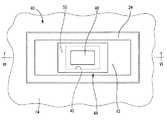
以下、本発明を更に具体的に明らかにするために、本発明の実施形態について説明する。先ず、図1〜2には、本発明の第一の実施形態としての制振装置10が示されている。制振装置10は、弾性プレート部材としての制振板12を備えており、かかる制振板12が制振対象となる振動部材としての自動車ボデー14の表面16に重ね合わせられて配設されている。これにより、制振装置10が、主振動系たるボデー14に装着されて、主振動系に対する副振動系を構成している。 Hereinafter, in order to clarify the present invention more specifically, embodiments of the present invention will be described. 1 to 2 show a
より詳細には、制振板12は、鉄やアルミニウム等の金属材やナイロン系樹脂等の樹脂材、或いはそれらの複合材等を用いて形成される。制振板12は、振動部材である自動車ボデー14の装着部位(表面16)の形状や大きさ、当該装着部位の質量や振動の周波数域等に応じて、その大きさや質量,形状が適当に設定されるものであり、特に限定されるものでないが、好ましくは、図示されているように矩形板形状とされる。 More specifically, the damping
特に、制振板12は、曲げ変形が比較的に容易に生ぜしめられるように、厚さ寸法に対して長さ寸法が充分に大きく設定されていることが望ましい。厚さ寸法:tに対する長さ寸法:Lが、好ましくは50≦L/t≦10000とされ、より好ましくは100≦L/t≦1000とされる。また、平面形状は必ずしも矩形状である必要はないが、安定した曲げ変形を生ぜしめさせるためには、矩形状であることが望ましい。その場合、幅寸法:Bは、振動部材(自動車ボデー14)に制振力を効果的に与えるために、1≦L/B≦10とされる。また、制振板12の曲げ共振による変形を安定して効率的に生ぜしめるために、制振板12は、その全体に亘って厚さ寸法が一定とされることが望ましい。更にまた、振動部材に対する制振効果を効果的に発揮させるためには、振動部材の表面16と制振板12の重ね合わせ面が何れも平坦であることが望ましい。 In particular, it is desirable that the damping
また、制振板12の曲げ強度は、入力される振動の大きさや振動部材の剛性(強度)等に応じて、制振板12の厚さ寸法を決定する際に考慮されることとなる。 Further, the bending strength of the damping
さらに、制振板12の質量は、防振すべき振動エネルギを考慮して決定されるが、一般に、自動車ボデー14における制振対象部位の質量の0.05〜10%程度が好適であり、より好ましくは0.1〜5%とされる。蓋し、余り質量が小さ過ぎると充分な制振効果を得ることが難しくなる一方、質量が大き過ぎると重量化が問題となり易い。 Furthermore, the mass of the damping
また、制振板12における一方(図2中、下)の表面18の全体や外周縁部(面)20、更に他方(図2中、上)の表面22の外周側における略矩形枠状の領域には、ゴム弾性層としての当接ゴム層24が被着形成されている。当接ゴム層24の材質としては、天然ゴム等のジエン系ゴムや塩素系ゴム等の各種のゴム弾性材が採用可能であり、本発明では、制振板12が振動部材である自動車ボデー14に打ち当たる際の打音が問題となる場合に、かかる打音を抑えることを主たる目的として当接ゴム層24が採用されることから、ゴム材料やゴム硬度は特に限定されない。制振板12が樹脂材である場合等においては、当接ゴム層24は必要でない場合が多い。尤も、打音低減の目的からすると、かかる当接ゴム層24としては、ショアD硬さが20〜40のゴム弾性材が好適に採用される。本実施形態では、当接ゴム層24の厚さ寸法が、全体に亘って略一定とされており、且つ、制振板12の厚さ寸法に比して十分に小さくされている。 In addition, a substantially rectangular frame shape on the outer peripheral side of the
このような制振板12の一方の表面18が、当接ゴム層24を介して自動車ボデー14の表面16に重ね合わせられている。ここにおいて、予めボデー14の制振すべき振動モード(本実施形態では、一次モード)を調査し、かかる振動モードの腹となる位置に制振板12が重ね合わせられている。なお、必ずしもボデー14の一次モードに合わせる必要はなく、二次以降のモードであっても振動モードの腹となる位置に合わせても良い。また、当接ゴム層24を備えた制振板12の表面18とボデー14における制振板12が重ね合わせられた部位、即ち振動モードの腹となる位置の表面16が、互いに平坦な水平面とされている。上述の説明からも明らかなように、ボデー14と制振板12との当接面が、ボデー14の表面16や制振板12の表面18を含んで構成されている。 One
また、制振板12の厚さ寸法は、制振板12が重ね合わせられた部位のボデー14の厚さ寸法よりも所定量だけ小さくされている。本実施形態では、制振板12の厚さ寸法:tと当該部位のボデー14の厚さ寸法:Tの比:T/tが、好ましくは1≦T/t≦10とされ、より好ましくは2≦T/t≦5とされる。 Further, the thickness dimension of the
また、ボデー14における制振板12の外周側には、位置決め手段としての支持金具26が設けられている。支持金具26には、鉄やアルミニウム合金等の金属材や合成樹脂材等が用いられる。支持金具26は、略一定の幅寸法で延びる略矩形枠状を有していると共に、全体に亘って略一定の厚さ寸法とされている。 Further, a support fitting 26 as a positioning means is provided on the outer peripheral side of the
さらに、支持金具26の幅方向中間部分には、厚さ方向(図2中、上下)に立ち上がる竪壁部28が形成されて段差形状とされている。支持金具26にあって、竪壁部28の一方(図2中、上)の端部から内周側に広がる矩形枠状の内側板部30が形成されていると共に、竪壁部28の他方(図2中、下)の端部から外周側に広がる、内側板部30よりも大きな矩形枠状の外側板部32が形成されている。即ち、支持金具26は、中央部分が僅かに上方に突出した矩形の逆皿形状とされており、その突出した中央部分には、矩形の窓部が形成されることにより、全体として矩形枠体形状とされているのである。 Furthermore, a
支持金具26の竪壁部28が制振板12を外周側から全体に亘って囲うように位置せしめられていると共に、支持金具26の外側板部32が、ボデー14の表面16に重ね合わせられて、溶接やボルト等で固着されている。それによって、制振板12の外周縁部20が支持金具26により自動車ボデー14に対して位置決めされて、制振板12が、自動車ボデー14の制振対象となる表面16上に安定して設置されている。 A
支持金具26の竪壁部28および内側板部30と当接ゴム層24を備えた制振板12の外周部分の間には、全体に亘って隙間34が形成されている。即ち、当接ゴム層24を備えた制振板12の長手寸法および幅寸法が、竪壁部28の長手寸法および幅寸法よりも小さくされている。これにより、竪壁部28と制振板12の外周縁部20に被着された当接ゴム層24が離隔距離:dを隔てて位置せしめられている。また、当接ゴム層24を備えた制振板12の厚さ寸法が、竪壁部28の高さ寸法よりも小さくされている。これにより、制振板12がボデー14に重ね合わせられた状態で、支持金具26の内側板部30と制振板12の他方の表面22の外周側に被着された当接ゴム層24が離隔距離:δを隔てて対向位置せしめられている。 A
本実施形態では、ボデー14の主たる振動入力方向(図2中、上下)の振動に対して有効な制振効果を得るために、支持金具26が、当接ゴム層24を備えた制振板12に対して、充分に大きな隙間を隔てて形成されている。要するに、制振板12の飛び跳ねや弾性変形,共振等に際して、支持金具26は、当接ゴム層24を備えた制振板12に対して干渉しないことが望ましい。しかし、制振板12は、ボデー14上において所定位置、即ち後述するように制振すべき振動モードで腹となる部分に対して安定して位置せしめられるようにすることが望ましい。それ故、支持金具26は、制振板12との干渉を極力避けつつ、制振板12の移動変位を所定範囲に抑えるように機能し得る大きさが設定されることとなる。 In the present embodiment, in order to obtain an effective damping effect against vibrations in the main vibration input direction (up and down in FIG. 2) of the
具体的には、例えば、本実施形態では、0.1mm≦δ≦1.0mm,0.1mm≦d≦5.0mmとされている。なお、制振板12がボデー14から離隔して竪壁部28の高さ方向中央に位置せしめられた状態で、制振板12の厚さ方向(図2中、上下)両側において、離隔距離:δ/2が確保されるようになっている。また、制振板12は、振動部材の表面上で、その長手方向と幅方向の何れの方向においても、それぞれ、距離:2dより大きな移動が阻止されるようになっている。 Specifically, for example, in this embodiment, 0.1 mm ≦ δ ≦ 1.0 mm and 0.1 mm ≦ d ≦ 5.0 mm. In the state where the damping
なお、制振板12の厚さ方向(上下方向)における支持金具26との間の隙間:δを、敢えて比較的に小さく設定することも、チューニング方法としては採用可能である。即ち、制振板12の曲げ変形や、飛び跳ね変位を考慮して、制振板12の外周縁部が当接する程に小さな隙間:δをもって、支持金具26を形成するのである。これにより、制振板12が曲げ変形せしめられたり、飛び跳ね変位することで、振動部材たる車両ボデー14に対して、それ自体の表面16だけでなく、車両ボデー14に固着された支持金具26に対しても、積極的に打ち当たるようにすることが出来る。要するに、制振板12が、その変形や変位に際して、そのストロークの両端で何れも打ち当たるようにすることで、打ち当たりによる制振効果を、振動部材に対してより一層効率的に作用せしめることが可能となるのである。 Note that it is also possible to adopt a relatively small gap δ between the damping
上述の如き制振装置10では、比較的に弾性率の大きな制振板12がボデー14の表面16に重ね合わせられて配設されているだけであるから、その弾性変形が表面16上で大きく許容されている。具体的には、制振板12の弾性変形のモデル図が図3,4に示されているように、主振動系たる自動車ボデー14の振動に伴い、制振板12がボデー14の表面16上で弾性変形する。なお、図3,4は、その変形状態を説明するために、著しく変形量を誇張して記載している。 In the
この変形は、制振板12の表面18がボデー14の表面16に当接した状態から、制振板12の中央部分がボデー14から次第に離隔して制振板12の外周部分だけがボデー14に当接した状態となる、全体として山状断面になったり(図3参照。)、制振板12の表面18がボデー14表面16に当接した状態から、制振板12の外周部分がボデー14から次第に離隔して制振板12の中央部分だけがボデー14に当接した状態となる、全体として谷状断面になったりする(図4参照。)。即ち、自動車ボデー14の振動に伴い、制振板12に曲げ振動が生ぜしめられ、この曲げ振動に基づいて、主振動系たるボデー14に対して振動減衰効果が発揮され得る。 In this deformation, from the state in which the
特に本実施形態では、制振板12における一次の固有振動数:fが、制振すべきボデー14の一次モードの振動周波数:Fの0.8〜2.0倍に、好適には1.0〜1.6倍にチューニングされている。換言すると、制振板12の固有振動数とボデー14の制振すべき振動周波数:Fとの関係が、0.8≦f/F≦2.0に、好適には1.0≦f/F≦1.6とされている。なお、制振すべき振動周波数:Fは、ボデー14の一次の固有振動数とされている。また、制振板12の固有振動数:fは、制振板12が自由支持された状態で測定されたものである。 In particular, in the present embodiment, the primary natural frequency f of the damping
けだし、制振板12の弾性変形に伴い制振板12とボデー14の当接面の大きさが漸増乃至は漸減することによって、制振板12のボデー14に対する支持形態が連続的に変化する。従って、制振板12の固有振動数が変化して、共振作用が広い周波数域に亘って発揮されるのであり、特に本発明者が多数の実験を行って検討したところ、1.0≦f/F≦1.6に設定されれば、極めて有効な制振効果が得られることが判明した。 However, as the size of the contact surface between the damping
それ故、制振板12の曲げ共振に基づいて大きな制振効果が効率的に得られることに加え、かかる制振効果が、制振板12とボデー14の当接面の変化による制振板12の固有振動数の変化を利用して、複数の乃至は広い周波数域に亘って有効に発揮され得るのである。 Therefore, in addition to efficiently obtaining a large vibration damping effect based on the bending resonance of the
また、振動入力時に、ボデー14と支持金具26の内側板部30の間において、制振板12がボデー14に対して相対変位して、ボデー14に打ち当たることにより、滑り摩擦作用や打撃作用によって制振効果が発揮され得る。このような制振板12のボデー14への打ち当たりに基づく制振効果は、明確な共振作用に基づくものでないことから、広い周波数域に亘って有効な制振効果を得ることが出来ると共に、温度による特性変化も抑えられて安定した制振効果を得ることが出来る。 Further, when the vibration is input, the
さらに、本発明者が詳細に検討したところ、制振板12における幅方向(図1中、上下)の一次曲げモードの固有振動数が自動車ボデー14の固有振動数に設定されること、即ち、制振板12の長さ方向(図1中、左右)のモードと幅方向のモードが互いに異なる固有振動数に設定されることにより、一つの制振板12で複数の振動モードに対する制振効果が効果的に得られることが確認された。また、ねじり方向等の他のモードでの、制振板12の共振によっても、同様な効果が発揮され得る。 Furthermore, when the inventor examined in detail, the natural frequency of the primary bending mode in the width direction (up and down in FIG. 1) of the damping
このことからも、本実施形態に係る制振装置10においては、特に矩形平板形状の制振板12が採用されていることによって、長さ方向のモードに加えて幅方向のモードを有効活用して、曲げ共振や滑り摩擦乃至は打撃によるエネルギ損失が効果的に発現されるため、例えば自動車ボデー14の固有振動数が変化する場合にも、所期の制振効果が安定して得られることが認められる。 For this reason as well, in the
加えて、本実施形態では、制振板12の質量が、自動車ボデー14における制振対象部位の質量の0.1〜5%とされている。これは、同じ制振対象部位に取り付けられる従来構造のダイナミックダンパや制振構造材等の質量と比べると、極めて小さな質量である。蓋し、目的とする制振効果が、主として制振板12の弾性変形による曲げ共振に基づき十分に得られることから、例えば、制振板12がボデー14に打ち当たる作用等の制振板12の質量に基づく制振効果について特別に考慮する必要がない。それ故、制振装置10の軽量化が有利に図られ得るのであり、特に、質量の制限が厳しい振動部材に対して好適に採用されることは言うまでもない。 In addition, in the present embodiment, the mass of the damping
次に、図5〜6には、本発明の第二の実施形態としての制振装置40が示されている。以下の説明において、前記第一の実施形態と実質的に同一の構造とされた部材および部位については、図中に第一の実施形態と同一の符号を付することにより、それらの詳細な説明を省略する。 Next, FIGS. 5 to 6 show a
詳細には、制振板12の中央部分には、略矩形状の位置決め用孔42が貫設されている。換言すると、本実施形態の制振板12が略矩形枠状を呈している。また、位置決め用孔42を構成する制振板12の内周縁部には、制振板12の一方の表面18に被着された当接ゴム層24が一体的に被着されており、更に、当接ゴム層24が制振板12の他方の表面22の内周側にも回されて、該表面22の内周側の略矩形枠状の領域に被着形成されている。この位置決め用孔42の内側にある自動車ボデー14に位置決め手段としての支持金具44が設けられている。 More specifically, a substantially
支持金具44は、略一定の厚さ寸法の矩形平板形状を有していると共に、金属材や合成樹脂材等の剛性材を用いて形成されている。また、支持金具44の中央部分が、プレス加工等によって、板厚方向の一方(図6中、下)に向かって矩形状に突出している。それによって、支持金具44の中央部分に矩形カップ状の内側板部46が一体形成されていると共に、内側板部46の外周縁部から軸方向一方(図6中、上)に延びる周壁部48の端部には、外周側に広がる矩形枠状の外側板部50が一体形成されている。内側板部46と外側板部50が、周壁部48の高さ寸法だけ相互に離隔されている。このような支持金具44の内側板部46が、制振板12の位置決め用孔42の内側におけるボデー14の表面16に重ね合わせられて、溶接やボルト等で固着されている。これにより、制振板12の位置決め用孔42の内周縁部が支持金具44により自動車ボデー14に対して位置決めされて、制振板12が、自動車ボデー14の制振対象となる表面16上に安定して設置されている。 The
また、支持金具44の周壁部48および外側板部50と当接ゴム層24を備えた制振板12の内周部分の間には、全体に亘って隙間52が形成されている。即ち、当接ゴム層24を備えた制振板12の位置決め用孔42の縦寸法および横寸法が、周壁部48の縦寸法および横寸法よりも大きくされている。これにより、周壁部48と制振板12の内周縁部に被着された当接ゴム層24が水平方向(図5中、上下左右)に所定の離隔距離を隔てて位置せしめられていると共に、制振板12がボデー14に重ね合わせられた状態で、支持金具44の外側板部50と制振板12の他方の表面22の内周側に被着された当接ゴム層24が鉛直方向(図6中、上下)に所定の離隔距離を隔てて対向位置せしめられている。 In addition, a
このような構造とされた制振装置40においても、制振板12は、支持金具26に対して実質的に干渉しないで、曲げ変形や飛び跳ね変位が許容されるように設定される。そして、曲げ変形や飛び跳ね変位に際して、制振板12は、ボデー14の表面16に対して打ち当たる。その結果、第一の実施形態と同様に有効な制振効果が発揮されるのである。 Also in the
なお、本実施形態では、制振板12の自由な変位を抑制して、その配設位置即ち打ち当たり位置を安定して設定するための支持金具26が、制振板12の中央部分に設けられている。これにより、外周の配設スペースが制限されるような場合において、マス質量を効率的に確保し得るスペース外周縁部において、制振板12の質量を有利に大きく設定することが可能となる。 In the present embodiment, a support metal fitting 26 is provided at the central portion of the damping
次に、図7〜8には、本発明の第三の実施形態としての制振装置55が示されている。かかる制振装置55の制振板12は、住宅やビル、乗り物等における振動部材としての窓ガラス56の表面57に重ね合わせられて配設されるようになっている。 Next, FIGS. 7 to 8 show a
詳細には、制振板12の一方の表面18が、鉛直方向(図7,8中、上下)に広がる窓ガラス56の一方の平坦な表面57に対して、重ね合わせられている。制振板12には、窓ガラス56に重ね合わされる方の表面18の全体に亘って、当接ゴム層24aが被着形成されている。この当接ゴム層24aは、全体に亘って一定厚さとされている。 Specifically, one
また、窓ガラス56の表面57には、上下一対の支持部材58がそれぞれ重ねあわされて固着されている。この支持部材58は、第一の実施形態の支持金具26と同じ断面形状を有する小幅の板形状とされている。一対の支持部材58,58が、上下方向で相互に離隔配置されて、相互に首を持ち上げるようにして対向せしめられている。 In addition, a pair of upper and
そして、窓ガラス56の表面57に重ね合わされて配設された制振板12が、かかる一対の支持部材58,58で上下を支持されている。即ち、本実施形態では、これら一対の支持部材58,58により、制振板12の変位量を制限する位置決め手段が構成されている。 The
なお、制振板12には、各支持部材58,58が重ね合わされる部分にも、薄肉の当接ゴム層24bが被着形成されている。 Note that a thin
また、制振板12の上下方向(図7,8中、上下)の寸法は、一対の支持部材58,58における縦壁部28,28間の対向面間距離よりも所定距離:d’だけ小さくされている。更にまた、制振板12の当接ゴム層24a,24bを含む厚さ寸法は、各支持部材58における縦壁部28の高さ寸法よりも所定距離:δ’だけ小さくされている。これにより、窓ガラス56の表面57に装着された制振板12は、一対の支持部材58,58により図8中の上下方向及び左右方向の変位量が制限された状態下において、弾性変形と、窓ガラス56からの離隔方向変位が許容されるようになっている。 Moreover, the dimension of the damping
特に本実施形態では、制振板12が、鉛直方向(図7,8中、上下)に広がる窓ガラス56の表面57に重ね合わせられて配設される、所謂縦置き構造とされていることから、制振板12の図7,8中、下方の外周縁部20が、重力作用で下方の支持部材58の竪壁部28に当接している。しかし、窓ガラス56が振動して、加振力が制振板12に及ぼされると、制振板12は、支持部材58から浮き上がって振動する。 In particular, in this embodiment, the damping
なお、窓ガラス56を、制振板12が重ね合わされた方の表面57が多少とも上方に向くように傾斜させても良い。このように窓ガラス56を上向き傾斜させた場合には、当接ゴム層24aと窓ガラス56の表面57の摩擦力等によって、制振板12の全周囲が、支持部材58から離れた状態で配設することも出来る。 Note that the
上述の如き構造とされた制振装置55においても、窓ガラス56が振動することに伴い、制振板12に対して曲げ変形や窓ガラス56からの飛び跳ね変位が生ぜしめられる。更に、制振板12の曲げ変形や飛び跳ね変位により、制振板12が窓ガラス56の表面57に対して打ち当たる。その結果、第一の実施形態や第二の実施形態と同様に、制振板12の曲げ共振作用や、それに加えての制振板12の窓ガラス56および支持部材58,58への打ち当たり作用に基づいて、有効な制振効果が発揮されるのである。 Also in the
なお、本実施形態では、例えば、窓ガラス56において防振すべき主たる振動の入力状態下での制振板12の振動モードにおいて、最も振幅が小さい背となる箇所が、支持部材58,58による支持部位となるように設定されることが望ましい。その結果、制振板12の曲げ変形が、支持部材58で不必要に拘束されることを軽減することが出来、曲げ共振や打ち当たり作用の更なる向上が図られ得る。 In the present embodiment, for example, in the vibration mode of the
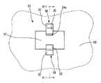
次に、図9〜10には、本発明の第四の実施形態としての制振装置80が示されている。制振装置80は、第一の実施形態に係る制振板と寸法等が異なるが同一の構造とされた制振板12を備えている。 Next, FIGS. 9 to 10 show a
詳細には、本実施形態に係る制振板12に、位置決め用孔82が貫設されている。位置決め用孔82の大きさや形状、数、位置等の形態は特に限定されるものでないが、本実施形態では、円形状を呈していると共に、制振板12の中央で長手方向(図9,10中、左右)に離隔して二つ設けられている。制振板12が金属材で形成されていることから、位置決め用孔82の周壁部には、金属が露出している。特に、これら位置決め用孔82,82は、制振板12の節の部分に位置せしめられている。 Specifically, a
また、制振板12には、ゴム弾性層としてのゴムキャップ84が設けられている。ゴムキャップ84は、中央ゴムキャップ84aと一対の端部ゴムキャップ84b,84bを含んで構成されている。 Further, the damping
中央ゴムキャップ84aは、厚肉の矩形平板形状を有していると共に、厚さ方向の中央部分には、長手方向(図10中、上下)の一方の端部に開口する矩形凹状の断面で幅方向(図10中、左右)に連続して延びて幅方向両端部に開口する嵌着溝86が形成されている。この嵌着溝86に、制振板12の幅方向(図10中、上下)の一方から、制振板12における一対の位置決め用孔82,82の間の中央部分が嵌め付けられていることで、中央ゴムキャップ84aが制振板12に取り付けられている。これにより、制振板12の中央部分が中央ゴムキャップ84aに挟まれて、中央部分の両面が中央ゴムキャップ84aで被覆されている。また、中央ゴムキャップ84aは制振板12の位置決め用孔82を避けた位置に設けられている一方、中央ゴムキャップ84aの幅方向の両端部が、各位置決め用孔82の開口縁部の上方に位置せしめられている。 The
また、端部ゴムキャップ84bは、厚肉の矩形平板形状を有していると共に、厚さ方向の中央部分には、長手方向(図10中、上下)の一方の端部に開口する矩形凹状の嵌着穴88が形成されている。この嵌着溝88に、制振板12の長手方向(図10中、左右)の一方から、制振板12の位置決め用孔82よりも端側の部分が嵌め付けられていることで、各端部ゴムキャップ84bが制振板12に取り付けられている。これにより、制振板12の長手方向両端部が端部ゴムキャップ84bに挟まれて、端部の両面が端部ゴムキャップ84bで被覆されている。また、端部ゴムキャップ84bは制振板12の位置決め用孔82を避けた位置に設けられている一方、各端部ゴムキャップ84bの長手方向の端部が、位置決め用孔82の開口縁部の上方に位置せしめられている。 The
これら中央ゴムキャップ84aおよび端部ゴムキャップ84b,84bを含んでなるゴムキャップ84は、第一の実施形態に係る当接ゴム層24と同様に、制振板12と自動車ボデー14が打ち当たる際の打音が問題となる場合に、かかる打音を抑えることを主たる目的として採用されることから、ゴム材料やゴム硬度は特に限定されない。本実施形態では、制振板12が金属材で形成されていることにより、打音低減を目的として、ゴムキャップ84には、ショアD硬さが20〜40のゴム弾性材が好適に採用される。 The rubber cap 84 including the
このようなゴムキャップ84を備えた制振板12が、自動車ボデー14の表面16に重ね合わせられている。特に、ゴムキャップ84の表面が自動車ボデー14の表面16に沿った形状(本実施形態では、平坦形状)とされているため、ゴムキャップ84と自動車ボデー14は、大きな隙間なく重ね合わせられている。本実施形態では、制振板12が、一方の表面に被覆されるゴムキャップ84の厚さ寸法の分だけ自動車ボデー14から離隔しているが、例えば撓みにより自動車ボデー14に当接していても良い。 The damping
また、位置決め用孔82の内側には、カラー部材90が配設されている。カラー部材90は、小径の円筒形状を呈していると共に、金属材を用いて形成されている。カラー部材90の外周面には、全体に亘って略一定の厚さ寸法のゴム層92が加硫接着等により固着されている。即ち、ゴム層92は、カラー部材90よりも一回り大きな円筒形状を呈している。このゴム層92の外径寸法が、位置決め用孔82の径寸法:D1よりも小さくされている。また、カラー部材90およびゴム層92の高さ寸法が、位置決め用孔82の軸方向寸法よりも大きくされており、更にゴムキャップ84を備えた制振板12の厚さ寸法よりも所定の距離:δ2だけ大きくされている。カラー部材90が非接着で位置決め用孔82に収容配置されて、自動車ボデー14に載置されている。また、カラー部材90には、位置決め用ボルト94が配設されている。 A
位置決め用ボルト94は、外周面に螺子部を備えた長軸の円柱部分の一方の端部において該円柱部よりも大径の円板形状を有するヘッド部96が一体形成された構造を呈している。位置決め用ボルト94の螺子部を備えた円柱部分の径寸法がカラー部材90の内径寸法よりも小さくされている。また、ヘッド部96の径寸法:D2が、カラー部材90に被着されたゴム層92の外径寸法よりも大きくされていると共に、更に位置決め用孔82の径寸法:D1よりも大きくされている。 The
そして、位置決め用ボルト94がカラー部材90に内挿されて、先端の螺子部が自動車ボデー14に螺着固定されている。位置決め用ボルト94のヘッド部96の外周部分が、制振板12の位置決め用孔82の開口部分のまわりや開口部分のまわりに被着されたゴムキャップ84に対して、制振板12と自動車ボデー14の重ね合わせ方向で対向位置せしめられている。特に、螺着固定に際して、自動車ボデー14に載置されたカラー部材90の上端部に位置決め用ボルト94のヘッド部96が当接していることで、ヘッド部96と自動車ボデー14の離隔距離が規定されている。制振板12に取り付けられたゴムキャップ84が自動車ボデー14に重ね合わせられている状態では、ヘッド部96とゴムキャップ84の間に所定の寸法:δ2の離隔距離が設定されている。 A
これにより、自動車ボデー14の表面16上において制振装置80が配設されており、その制振板12が複数(本実施形態では2つ)の位置決め用ボルト94に対して実質的に干渉しないで、曲げ変形や飛び跳ね変位が許容されている。そして、自動車ボデー14の振動入力に伴い制振板12に曲げ変形や飛び跳ね変位が生ぜしめられて、制振板12がゴムキャップ84を介して自動車ボデー14に打ち当たる。その結果、第一の実施形態と同様に、有効な制振効果が発揮され得るのである。 Thereby, the
そこにおいて、制振板12が曲げ変形や飛び跳ね変位する際に、位置決め用孔82のまわりに被着されたゴムキャップ84が位置決め用ボルト94のヘッド部96に当接することによって、自動車ボデー14に対する制振板12の位置ずれが阻止されて、配設状態が保持される。これにより、安定した制振効果が得られる。上述の説明からも明らかなように、本実施形態の位置決め手段が、位置決め用孔82や位置決め用ボルト94を含んで構成されている。 In this case, when the
特に本実施形態では、例示の如き位置決め用ボルト94を用いて制振板12の自動車ボデー14に対する位置決めがなされるため、例えば位置決め手段として自動車ボデー14の表面16に沿った形状のハウジングを特別に採用する必要がなくなり、位置決め機構が簡単に実現され得る。従って、本実施形態のような平坦形状の表面を有する自動車ボデー14や制振板12に限らず、例えば湾曲形状のものに対しても、位置決め機構が簡単に実現され得るのである。 In particular, in the present embodiment, since the damping
また、本実施形態では、位置決め用ボルト94および位置決め用孔82からなる位置決め機構が、制振板12の中央から離れた二箇所に設けられていることで、制振板12の中心軸回りの過度な回転が制限されることから、制振板12の自動車ボデー14に対する位置決めが一層確実になる。 Further, in this embodiment, the positioning mechanism including the
さらに、本実施形態においては、カラー部材90の外周面にゴム層92が被着形成されていることによって、制振板12が平面方向に変位してカラー部材90と位置決め用孔82の周壁部が当接する際に、ゴム層92を介して当接することとなる。それ故、当接に際しての打音の低減効果が有利に図られ得る。 Further, in the present embodiment, the
更にまた、本実施形態に係るゴム弾性層として、制振板12と別体形成された嵌め込み式のゴムキャップ84が採用されているので、製造が容易となる。しかも、要求される打音低減効果や自動車ボデー14への配設状態、或いは制振板12の弾性変形や質量に応じて、ゴムキャップ84に代えて当該ゴムキャップ84と形状や大きさ等が異なるゴムキャップを装着したり、ゴムキャップ84を取り外すことも実現可能となる。 Furthermore, since the fitting-type rubber cap 84 formed separately from the
以上、本発明の実施形態について詳述してきたが、これらはあくまでも例示であり、これら実施形態における具体的な記載によって、本発明は、何等限定されるものでなく、当業者の知識に基づいて種々なる変更、修正、改良等を加えた態様で実施可能である。また、そのような実施態様が、本発明の趣旨を逸脱しない限り、何れも、本発明の範囲内に含まれるものであることは、言うまでもない。 Although the embodiments of the present invention have been described in detail above, these are merely examples, and the present invention is not limited to specific descriptions in these embodiments, and is based on the knowledge of those skilled in the art. The present invention can be implemented with various changes, modifications, improvements, and the like. Further, it goes without saying that such embodiments are all included in the scope of the present invention without departing from the gist of the present invention.
例えば、制振板12や支持金具26,44、支持部材58における形状や大きさ、構造、数、ボデー14や窓ガラス56に対する配置等の形態は、例示の如きものに限定されるものでない。 For example, the shape, size, structure, number, and arrangement of the damping
具体的には、前記実施形態において、一つの制振板12が、ボデー14における一次の振動モードの腹となる位置に設けられていたが、例えば一つの振動モードの腹に複数の制振板を設けたり、一次等の低次の振動モードを含む複数の振動モードの各腹となる位置に、それぞれ一又は二以上の制振板を設けたりすること等によって、ボデーの表面上で異なる位置に複数の制振板を重ね合わせて配設することが可能である。 Specifically, in the above-described embodiment, one damping
また、制振板12は、振動部材における振動モードの腹となる位置に必ずしも設けられる必要はなく、腹をはずれた位置に設けることも勿論可能である。 Further, the damping
さらに、当接ゴム層24は、制振板12のボデー14への打ち当たり部位だけに設けられていれば良い。尤も、前述の如く、この当接ゴム層24は、本発明において必須ではない。例えば、当接ゴム層24を、制振板12の一方の面の全面に亘って覆うように被着形成する他、全外表面を覆うように被着形成しても良い。 Furthermore, the
更にまた、前記実施形態では、ボデー14と制振板12の重ね合わせ面となるボデー14の表面16と制振板12の一方の表面18が、互いに平坦な水平面とされていた。しかしながら、制振板12の共振モードにおいて、複数の箇所でボデー14への打ち当たりが発生するものであれば、本発明の効果が有効に発揮される。従って、例えば、表面に凹凸を有する振動部材に対して、打ち当たり面が全体に亘って平面形状とされた弾性プレート部材を重ね合わせて採用することも可能である。或いは、表面が湾曲面や傾斜面等の各種異形状とされた振動部材に対して、その表面に沿って同様な異形状とされた弾性プレート部材を重ね合わせて採用することも可能である。また、例えば、振動部材において、水平方向に対して所定の角度で傾斜した平坦な傾斜面に沿って、平面形状の弾性プレート部材を重ね合わせることにより、弾性プレート部材が傾斜した状態で配設されるようにしても良い。 Furthermore, in the above embodiment, the
また、前記第四の実施形態では、位置決め手段として金属製の位置決め用ボルト94が用いられていたが、例えば位置決め手段がゴム弾性材や合成樹脂材等からなるピンやリベット等で構成される場合や、位置決め用ボルト94と制振板12の当接打音が問題とならない場合等には、ゴムキャップ84を必ずしも設ける必要はない。また、同様な理由により、カラー部材90に被着されるゴム層92も必須の部材でない。
Further, in the fourth embodiment, the
以下、本発明に係る制振装置の制振効果について検証するために、本発明の実施例について説明するが、本発明がかかる実施例の形態に限定されるものでない。例えば、本実施例では、特に制振板の曲げ共振や振動部材への打ち当たり作用による制振効果を容易に把握する目的で、位置決め手段を実施の形態の構成要件から除いている。 Hereinafter, in order to verify the damping effect of the vibration damping device according to the present invention, an embodiment of the present invention will be described, but the present invention is not limited to the embodiment. For example, in this embodiment, the positioning means is excluded from the configuration requirements of the embodiment in order to easily grasp the damping effect due to the bending resonance of the damping plate and the striking action against the vibrating member.
先ず、図11に示される如き実験装置60を準備する。実験装置60は、振動部材としてのベース62を備えている。ベース62は、矩形平板形状を有しており、鉄等の剛性材を用いて形成する。ベース62の両端部分を加振機64に固定する。また、加振機64によるスイープ加振または正弦波加振をベース62に及ぼしたり、或いはベース62の所定の箇所にインパルスハンマによる打撃加振を与えて、FEM等のモード解析によりベース62の一次の振動モードを調査すると共に、ベース62の一次の固有振動数:Fを測定する。 First, an
また、ベース62の一次の振動モードの腹となる位置に弾性プレート部材としての制振板66を重ね合わせて配設する。制振板66は、矩形平板形状を有していると共に、弾性を有する金属材を用いて形成する。ここにおいて、ベース62の一次の固有振動数:Fに比して所定量だけ高い一次の固有振動数:faを備えた制振板66aと、ベース62の一次の固有振動数:Fと略同じ一次の固有振動数:fbを備えた制振板66bと、ベース62の一次の固有振動数:Fに比して所定量だけ低い一次の固有振動数:fcを備えた制振板66cを準備する。 In addition, a damping
そして、制振板66a,66b,66cを、各別にベース62の腹に重ね合わせた状態で、加振機64やインパルスハンマによりベース62に加振力を及ぼして得られる振動レベル(dB)を、公知のレーザ振動計68を用いて測定した。その結果、制振板66a,66b,66cが配設された各ベース62の振動レベルの測定結果を、図12,13,14に、それぞれ実施例1,2,3として示す。また、図12,13,14には、ベース62に制振板66a,66b,66cを配設していない状態で、ベース62の振動レベルを測定した結果を比較例として併せ示す。 The vibration level (dB) obtained by applying a vibration force to the
図12,13,14に示される結果からも、ベース62の固有振動数:Fと略同じチューニング周波数の制振板66bを備えた制振装置に加えて、ベース62の固有振動数:Fから所定量だけ外れたチューニング周波数の制振板66a,66cを備えた制振装置の何れにおいても、制振効果が有効に発揮されることが認められる。 From the results shown in FIGS. 12, 13, and 14, in addition to the vibration damping device including the vibration damping plate 66 b having the tuning frequency substantially the same as that of the natural frequency F of the
また、図11に示される実験装置60において、チューニング周波数がそれぞれ異なる制振板66の複数を用意し、制振板66の固有振動数:fとベース62の固有振動数:Fとの比:f/Fが、0.8≦f/F≦2.3の範囲で、各別に異なる値における各制振板66を配設したベース62の制振効果(dB)について、それぞれ測定した。その結果を表1に示す。なお、表1には、各比:f/Fの条件下において、制振効果を複数回測定した結果を示す。 Further, in the

表1からも、0.8≦f/F≦2.3の関係が成り立つ制振装置の何れにあっても、制振効果が発揮され得ることが認められ、特に、1.0≦f/F≦1.6の範囲の制振装置では、制振対象のベース62において要求される20dB前後の制振効果が有効に得られることが明らかである。 It can be seen from Table 1 that the vibration damping effect can be exerted in any vibration damping device that satisfies the relationship 0.8 ≦ f / F ≦ 2.3. It is apparent that the vibration damping effect in the range of F ≦ 1.6 can effectively obtain the vibration damping effect of around 20 dB required in the base 62 to be controlled.
従って、本発明に従う構造とされた制振装置においては、制振板66のチューニング周波数が制振すべきベース62の固有振動数から多少ずれていたとしても、制振板66の弾性変形による制振板66とベース62の当接面の変化に伴い、制振板66の固有振動数が変化して、共振作用が実質的に広い周波数域に亘って発揮されることとなり、それによって、所期の制振効果が安定して得られるものと考える。 Therefore, in the vibration damping device having the structure according to the present invention, even if the tuning frequency of the
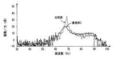
次に、図15には、本発明の別の制振効果について確認するための実験装置70が示されている。実験装置70は、振動部材としての薄肉の矩形平板形状を有するベース72を備えている。ベース72の外周部分を基台に固定する。また、ベース72の所定の位置:Pにインパルスハンマによる打撃加振を及ぼして、FEM等のモード解析によりベース72の振動モードに係る一次と二次を調査すると共に、ベース62の一次の固有振動数:F1と二次の固有振動数:F2を測定する。Next, FIG. 15 shows an
また、ベース72の一次の振動モードの腹となる位置に弾性プレート部材としての制振板74aを重ね合わせて配設すると共に、ベース72の二次の振動モードの腹となる位置に弾性プレート部材としての制振板74b,74bを重ね合わせて配設する。ここにおいて、制振板74aの固有振動数をベース72の一次の固有振動数:F1にチューニングしていると共に、制振板74aの固有振動数をベース72の一次の固有振動数:F2にチューニングしている。Further, a damping
そして、制振板74a,74b,74bを、ベース72の各振動モードの腹に重ね合わせた状態で、インパルスハンマによりベース72の所定の位置:Pに加振力を及ぼして得られる振動レベル(dB)を測定した。その結果を、図16に実施例として示す。また、図16には、ベース72に制振板74a,74b,74bを配設していない状態で、ベース72の振動レベルを測定した結果を比較例として併せ示す。 The vibration level (obtained by applying an excitation force to a predetermined position P of the base 72 by the impulse hammer with the
図16からも、ベース72における複次の振動モードの腹に対して、それぞれ各モードの固有振動数にチューニングされた制振板74が重ね合わせられるだけの簡単な構造において、制振効果が有利に発揮されることが認められる。しかも、制振板74を複数配設しても、制振板74の質量は軽いことから、従来構造のダイナミックダンパや制振構造材に比して軽量化が有利に図られつつ、優れた制振効果が得られることが推考される。
Also from FIG. 16, the damping effect is advantageous in a simple structure in which the damping plate 74 tuned to the natural frequency of each mode is superimposed on the antinode of the secondary vibration mode in the
10:制振装置、12:制振板、14:自動車ボデー、16:表面、26:支持金具10: Damping device, 12: Damping plate, 14: Car body, 16: Surface, 26: Support bracket
Claims (8)
Translated fromJapanesePriority Applications (3)
| Application Number | Priority Date | Filing Date | Title |
|---|---|---|---|
| JP2006079338AJP2007120744A (en) | 2005-09-29 | 2006-03-22 | Vibration suppression device |
| US11/527,570US20070069434A1 (en) | 2005-09-29 | 2006-09-27 | Vibration damping device |
| DE102006000487ADE102006000487A1 (en) | 2005-09-29 | 2006-09-28 | Vibration damping device |
Applications Claiming Priority (2)
| Application Number | Priority Date | Filing Date | Title |
|---|---|---|---|
| JP2005284896 | 2005-09-29 | ||
| JP2006079338AJP2007120744A (en) | 2005-09-29 | 2006-03-22 | Vibration suppression device |
Publications (1)
| Publication Number | Publication Date |
|---|---|
| JP2007120744Atrue JP2007120744A (en) | 2007-05-17 |
Family
ID=37892890
Family Applications (1)
| Application Number | Title | Priority Date | Filing Date |
|---|---|---|---|
| JP2006079338APendingJP2007120744A (en) | 2005-09-29 | 2006-03-22 | Vibration suppression device |
Country Status (3)
| Country | Link |
|---|---|
| US (1) | US20070069434A1 (en) |
| JP (1) | JP2007120744A (en) |
| DE (1) | DE102006000487A1 (en) |
Cited By (1)
| Publication number | Priority date | Publication date | Assignee | Title |
|---|---|---|---|---|
| JP2016088313A (en)* | 2014-11-05 | 2016-05-23 | 三菱重工業株式会社 | Compressor device for railway and railway vehicle |
Families Citing this family (13)
| Publication number | Priority date | Publication date | Assignee | Title |
|---|---|---|---|---|
| US9099074B1 (en) | 2003-10-21 | 2015-08-04 | Peter A. Lucon | Custom tunable acoustic insulation |
| US8418474B2 (en)* | 2008-01-29 | 2013-04-16 | Alstom Technology Ltd. | Altering a natural frequency of a gas turbine transition duct |
| US9121180B2 (en)* | 2009-09-14 | 2015-09-01 | Bwdt, Llc | System for mounting objects to polymeric membranes |
| US8499524B2 (en)* | 2009-09-14 | 2013-08-06 | Joel A. Stanley | System for mounting objects to polymeric membranes |
| WO2012112637A1 (en)* | 2011-02-15 | 2012-08-23 | Stanley Joel A | System for mounting objects to polymeric membranes |
| US9121545B2 (en) | 2009-09-14 | 2015-09-01 | Bwdt, Llc | System for mounting objects to polymeric membranes |
| US8557070B2 (en) | 2009-09-14 | 2013-10-15 | Joel A. Stanley | Method of mounting objects to polymeric membranes |
| US8623158B2 (en) | 2009-09-14 | 2014-01-07 | Joel A. Stanley | System for mounting objects to polymeric membranes |
| US8608884B2 (en) | 2009-09-14 | 2013-12-17 | Joel A. Stanley | Method and system for mounting objects to polymeric membranes |
| US9175479B2 (en) | 2009-09-14 | 2015-11-03 | Bwdt, Llc | System for mounting objects to polymeric membranes |
| US9810279B2 (en) | 2010-09-10 | 2017-11-07 | Northrop Grumman Systems Corporation | Vibratory bandgap device |
| DE102013205230B3 (en)* | 2013-03-25 | 2014-07-31 | Federal-Mogul Sealing Systems Gmbh | Vibration damper for shielding plate |
| CN110030319B (en)* | 2019-04-28 | 2024-04-19 | 苏州蓝博控制技术有限公司 | Full laminating instrument top vibration damper and full laminating instrument |
Citations (3)
| Publication number | Priority date | Publication date | Assignee | Title |
|---|---|---|---|---|
| JPH07293659A (en)* | 1994-04-20 | 1995-11-07 | Nippon Seiko Kk | Ball screw device |
| JPH08193640A (en)* | 1994-11-18 | 1996-07-30 | Bridgestone Corp | Dynamic damper |
| JP2001241498A (en)* | 2000-03-01 | 2001-09-07 | Tokai Rubber Ind Ltd | Vibration damping device for vehicle |
Family Cites Families (9)
| Publication number | Priority date | Publication date | Assignee | Title |
|---|---|---|---|---|
| US2009614A (en)* | 1933-06-19 | 1935-07-30 | Gen Motors Corp | Antisqueak body bracket |
| US5613400A (en)* | 1994-01-18 | 1997-03-25 | Nsk Ltd. | Ball screw device with resonance preventing means for a screw shaft and table drive device including the same |
| JPH11230245A (en)* | 1998-02-10 | 1999-08-27 | Tokai Rubber Ind Ltd | Pneumatically oscillating active damper |
| JPH11247919A (en)* | 1998-03-04 | 1999-09-14 | Tokai Rubber Ind Ltd | Fluid sealed active vibration control device |
| EP1128086A2 (en)* | 2000-02-28 | 2001-08-29 | Tokai Rubber Industries, Ltd. | Vibration-damping device for vehicles |
| JP2001241497A (en)* | 2000-03-01 | 2001-09-07 | Tokai Rubber Ind Ltd | Vibration damping device for vehicle |
| US6817456B2 (en)* | 2001-03-30 | 2004-11-16 | Tokai Rubber Industries, Ltd. | Dynamic damper for steering system |
| US6511059B2 (en)* | 2001-05-01 | 2003-01-28 | Paulstra Crc | Antivibration device and mechanical assembly comprising such antivibration device |
| JP3867594B2 (en)* | 2002-03-12 | 2007-01-10 | 東海ゴム工業株式会社 | Vibration damping device performance evaluation apparatus and performance evaluation method |
- 2006
- 2006-03-22JPJP2006079338Apatent/JP2007120744A/enactivePending
- 2006-09-27USUS11/527,570patent/US20070069434A1/ennot_activeAbandoned
- 2006-09-28DEDE102006000487Apatent/DE102006000487A1/ennot_activeWithdrawn
Patent Citations (3)
| Publication number | Priority date | Publication date | Assignee | Title |
|---|---|---|---|---|
| JPH07293659A (en)* | 1994-04-20 | 1995-11-07 | Nippon Seiko Kk | Ball screw device |
| JPH08193640A (en)* | 1994-11-18 | 1996-07-30 | Bridgestone Corp | Dynamic damper |
| JP2001241498A (en)* | 2000-03-01 | 2001-09-07 | Tokai Rubber Ind Ltd | Vibration damping device for vehicle |
Cited By (1)
| Publication number | Priority date | Publication date | Assignee | Title |
|---|---|---|---|---|
| JP2016088313A (en)* | 2014-11-05 | 2016-05-23 | 三菱重工業株式会社 | Compressor device for railway and railway vehicle |
Also Published As
| Publication number | Publication date |
|---|---|
| US20070069434A1 (en) | 2007-03-29 |
| DE102006000487A1 (en) | 2007-05-03 |
Similar Documents
| Publication | Publication Date | Title |
|---|---|---|
| JP2007120744A (en) | Vibration suppression device | |
| JP6190651B2 (en) | Vibration isolator | |
| JP3846208B2 (en) | Vibration control device for vehicle | |
| JP2003014035A (en) | Vibration damping device | |
| JP3772715B2 (en) | Vibration control device | |
| JP4971065B2 (en) | Damping device for building structure | |
| US20070221460A1 (en) | Vibration damping device for internal combustion engine | |
| JP5427095B2 (en) | Vibration isolator | |
| JP2007205438A (en) | Vibration damping device | |
| JP4656433B2 (en) | Vibration control device | |
| JP2008202608A (en) | Vibration damping device | |
| JP2005076662A (en) | Contact type damping device | |
| JP2002081494A (en) | Vehicular vibration damper | |
| JP2004028125A (en) | Dynamic damper | |
| JP5606892B2 (en) | Vibration isolator | |
| JP2009263864A (en) | Vibration control device for floor vibration and floor impact sound | |
| JP2003194140A (en) | Damper | |
| JP4505750B2 (en) | Vibration control device | |
| JP4881810B2 (en) | Leaf spring type damping device | |
| JP4088955B2 (en) | Vibration control device | |
| JP2003287078A (en) | Shock absorber for vehicle | |
| JP4066456B2 (en) | Cylindrical vibration isolator | |
| JP2000356243A (en) | Vibration control device | |
| CN108571247A (en) | Vibration absorber containing self-amplitude-limiting vibration mass block | |
| JP3972292B2 (en) | Shock absorber for vehicles |
Legal Events
| Date | Code | Title | Description |
|---|---|---|---|
| A621 | Written request for application examination | Free format text:JAPANESE INTERMEDIATE CODE: A621 Effective date:20080820 | |
| A131 | Notification of reasons for refusal | Free format text:JAPANESE INTERMEDIATE CODE: A131 Effective date:20100126 | |
| A977 | Report on retrieval | Free format text:JAPANESE INTERMEDIATE CODE: A971007 Effective date:20100128 | |
| A02 | Decision of refusal | Free format text:JAPANESE INTERMEDIATE CODE: A02 Effective date:20100524 |