JP2007115352A - Magnetic disk device - Google Patents
Magnetic disk deviceDownload PDFInfo
- Publication number
- JP2007115352A JP2007115352AJP2005306462AJP2005306462AJP2007115352AJP 2007115352 AJP2007115352 AJP 2007115352AJP 2005306462 AJP2005306462 AJP 2005306462AJP 2005306462 AJP2005306462 AJP 2005306462AJP 2007115352 AJP2007115352 AJP 2007115352A
- Authority
- JP
- Japan
- Prior art keywords
- head slider
- magnetic head
- magnetic disk
- magnetic
- bearing surface
- Prior art date
- Legal status (The legal status is an assumption and is not a legal conclusion. Google has not performed a legal analysis and makes no representation as to the accuracy of the status listed.)
- Pending
Links
- 230000002093peripheral effectEffects0.000claimsdescription134
- 239000000725suspensionSubstances0.000claimsdescription34
- 238000005520cutting processMethods0.000claimsdescription9
- 238000007790scrapingMethods0.000claims1
- 230000007423decreaseEffects0.000abstractdescription4
- 230000006866deteriorationEffects0.000description20
- 238000013459approachMethods0.000description8
- 238000010586diagramMethods0.000description8
- 230000002542deteriorative effectEffects0.000description3
- 238000003860storageMethods0.000description3
- 238000005266castingMethods0.000description1
- 230000015556catabolic processEffects0.000description1
- 238000005352clarificationMethods0.000description1
- 239000000470constituentSubstances0.000description1
- 238000013500data storageMethods0.000description1
- 230000003247decreasing effectEffects0.000description1
- 238000006731degradation reactionMethods0.000description1
- 239000000428dustSubstances0.000description1
- 230000000694effectsEffects0.000description1
- 238000005530etchingMethods0.000description1
- 238000002474experimental methodMethods0.000description1
- 238000005339levitationMethods0.000description1
- 238000004519manufacturing processMethods0.000description1
- 230000015654memoryEffects0.000description1
- 238000000034methodMethods0.000description1
- 230000003287optical effectEffects0.000description1
- 230000010355oscillationEffects0.000description1
- 230000002265preventionEffects0.000description1
- 238000001179sorption measurementMethods0.000description1
- 230000003746surface roughnessEffects0.000description1
- 238000011144upstream manufacturingMethods0.000description1
Images


Classifications
- G—PHYSICS
- G11—INFORMATION STORAGE
- G11B—INFORMATION STORAGE BASED ON RELATIVE MOVEMENT BETWEEN RECORD CARRIER AND TRANSDUCER
- G11B5/00—Recording by magnetisation or demagnetisation of a record carrier; Reproducing by magnetic means; Record carriers therefor
- G11B5/48—Disposition or mounting of heads or head supports relative to record carriers ; arrangements of heads, e.g. for scanning the record carrier to increase the relative speed
- G11B5/58—Disposition or mounting of heads or head supports relative to record carriers ; arrangements of heads, e.g. for scanning the record carrier to increase the relative speed with provision for moving the head for the purpose of maintaining alignment of the head relative to the record carrier during transducing operation, e.g. to compensate for surface irregularities of the latter or for track following
- G11B5/60—Fluid-dynamic spacing of heads from record-carriers
- G11B5/6005—Specially adapted for spacing from a rotating disc using a fluid cushion
Landscapes
- Adjustment Of The Magnetic Head Position Track Following On Tapes (AREA)
Abstract
Translated fromJapaneseDescription
Translated fromJapanese本発明は磁気ディスク装置に関し、特に、磁気ディスクにデータの記録・再生を行うヘッドスライダを有する磁気ディスク装置の構成に関する。 The present invention relates to a magnetic disk device, and more particularly to a configuration of a magnetic disk device having a head slider for recording / reproducing data on / from a magnetic disk.
データ記憶装置として、光ディスクや磁気テープなどの様々な態様のメディアを使用する装置が知られているが、その中で、磁気ディスク装置であるハードディスク・ドライブ(HDD)は、コンピュータの記憶装置として広く普及し、現在のコンピュータ・システムにおいて欠かすことができない記憶装置の一つとなっている。さらに、コンピュータ・システムにとどまらず、動画像記録再生装置、カー・ナビゲーション・システム、あるいはデジタル・カメラなどで使用されるリムーバブル・メモリなど、HDDの用途は、その優れた特性により益々拡大している。 As data storage devices, devices using various types of media such as optical disks and magnetic tapes are known. Among them, hard disk drives (HDDs), which are magnetic disk devices, are widely used as computer storage devices. It has become one of the storage devices that are indispensable and indispensable in current computer systems. In addition to computer systems, HDD applications such as moving image recording / playback devices, car navigation systems, and removable memories used in digital cameras are increasingly expanding due to their superior characteristics. .
HDDでは、回転する磁気ディスク上で微少な間隔(浮上量)を保ちながら浮上する磁気ヘッドスライダが使用される。通常、磁気ヘッドスライダはスライダの空気流出端にディスク記録媒体に対してデータを記録・再生する磁気トランスデューサを備えている。HDDでは、記憶容量を高めるためにビット(円周方向の記録)密度及びトラック(半径方向の記録)密度を更に高めることが求められる。とくに、ビット密度を高める技術のひとつとして、可能な限り磁気ディスクに近接した低浮上状態でスライダを浮上させることが要求される。現在、こうした厳しい低浮上化を実現するため、磁気ディスクにスライダを引き付ける向きの負圧力を利用した浮上安定性に優れた負圧型のスライダが使用される。 In the HDD, a magnetic head slider that floats on a rotating magnetic disk while maintaining a minute interval (flying amount) is used. Usually, the magnetic head slider is provided with a magnetic transducer for recording / reproducing data on / from a disk recording medium at the air outflow end of the slider. In the HDD, it is required to further increase the bit (circumferential recording) density and the track (radial recording) density in order to increase the storage capacity. In particular, as one of the techniques for increasing the bit density, it is required to float the slider in a low flying state as close to the magnetic disk as possible. At present, in order to realize such a severely low flying height, a negative pressure type slider having excellent flying stability using a negative pressure in the direction of attracting the slider to the magnetic disk is used.
HDDは、磁気ヘッドスライダを磁気ディスク上の所望の位置に移動するアクチュエータをさらに備えている。アクチュエータはボイス・コイル・モータ(Voice Coil Motor:VCM)によって駆動され、揺動軸を中心として揺動することによって、回転する磁気ディスク上で磁気ヘッドスライダを半径方向に移動する。これによって、磁気トランスデューサが磁気ディスクに形成された所望のトラックにアクセスし、データの読み出し/書き込み処理を行うことができる。 The HDD further includes an actuator that moves the magnetic head slider to a desired position on the magnetic disk. The actuator is driven by a voice coil motor (VCM) and oscillates about an oscillation axis, thereby moving the magnetic head slider in the radial direction on the rotating magnetic disk. As a result, the magnetic transducer can access a desired track formed on the magnetic disk and perform data read / write processing.
また、ロード・アンロード方式のHDDは、磁気ヘッドスライダが磁気ディスク面上から退避するランプを備えている。ランプは、磁気ディスク外周端部に近接して配置される。磁気ディスクの回転が停止すると、磁気ヘッドスライダが磁気ディスク表面に吸着されるため、磁気ディスクの回転が停止するときには、アクチュエータは磁気ヘッドスライダを磁気ディスクの記録面からランプに退避させる。 Further, the load / unload type HDD includes a ramp for retracting the magnetic head slider from the surface of the magnetic disk. The ramp is disposed close to the outer peripheral edge of the magnetic disk. When the rotation of the magnetic disk stops, the magnetic head slider is attracted to the surface of the magnetic disk. Therefore, when the rotation of the magnetic disk stops, the actuator retracts the magnetic head slider from the recording surface of the magnetic disk to the ramp.
アクチュエータは、磁気ヘッドスライダを支持するサスペンションとアームを有している。サスペンションの先端には、タブが設けられており、ランプにタブが誘導されることで、磁気ヘッドスライダが磁気ディスク面上から外側へと退避してアンロードが行われ、反対にランプからタブが離れることで、磁気ヘッドスライダが磁気ディスクの外側から磁気ディスク面上へ移動してロードが行われる。 The actuator has a suspension and an arm that support the magnetic head slider. A tab is provided at the tip of the suspension. When the tab is guided to the ramp, the magnetic head slider is retracted from the surface of the magnetic disk to the outside, and unloading is performed. By moving away, the magnetic head slider moves from the outside of the magnetic disk onto the surface of the magnetic disk, and loading is performed.
図10は、従来のHDDにおいて、ロード時の磁気ヘッドスライダの状態を示している。磁気ヘッドスライダ905は、サスペンション910に設けられたディンプル960によって一点支持されている。ロード時、タブ916がランプ902の表面を摺動することで、サスペンション910が磁気ディスク901上へ下降していく。そして、サスペンション910が磁気ディスク901上へ下降するにしたがって、磁気ヘッドスライダ905が磁気ディスク901の表面に近づいていく。磁気ヘッドスライダ905をサスペンション910に取り付ける際のバラツキやねじれにより、ロード時に、磁気ヘッドスライダ905がスライダ短手方向に対し傾斜しながら近づく場合がある。近年、磁気ヘッドスライダ905の浮上量が低下しているため、磁気ヘッドスライダ905と磁気ディスク901が極端に近づくことになり、磁気ヘッドスライダ905の端部と磁気ディスク901の表面とが接触する場合がある(図10の接触部920)。磁気ヘッドスライダ905と磁気ディスク901が接触すると、磁気ディスク901の面が損傷されうるため、この接触部920を含む領域は、データの記録・再生に用いられないロード・アンロード領域921となっている。ロード・アンロード領域921より半径方向内側の領域が、データの記録・再生に用いるデータ記録領域922となる。すなわち、接触部920の近傍領域は、データ記録に適さないため、記録領域が減少してしまう。 FIG. 10 shows the state of the magnetic head slider during loading in a conventional HDD. The
ロード時に、磁気ヘッドスライダと磁気ディスクとの接触によって記録媒体が損傷しうるという問題を解決する磁気ヘッドスライダとして、特許文献1〜3が知られている。特許文献1では、磁気ヘッドスライダを台形状としている。特許文献2では、ABS(Air Bearing Surface)面に切り欠きを形成している。特許文献3では、空気流出端をコーナからセンターパッド(リアパッド)近傍まで掘り下げている。
磁気ヘッドスライダと磁気ディスクとの接触を防止するため、上記特許文献のように、磁気ヘッドスライダの形状を大きく変えたり、ABS面や空気流出端を大きく削ってしまうと、浮上特性に影響するという問題がある。また、特許文献3には、コーナの掘り下げ部の深さや表面粗さ等の外見は浮上特性には殆ど影響しないと記載されている。しかしながら、近年、スライダの小型化が進んでおり、ABS面や空気流出端を含めスライダの形状を変更すると、フェムトスライダのように小さなスライダでは特に浮上特性に大きく影響することがわかってきた。 In order to prevent contact between the magnetic head slider and the magnetic disk, if the shape of the magnetic head slider is greatly changed or the ABS surface and the air outflow end are greatly shaved as in the above-mentioned patent document, the flying characteristics are affected. There's a problem. Further,
本発明は、こうした問題に鑑みなされたものであり、本発明の目的は、浮上特性の劣化を抑止しつつ、ロード時の磁気ヘッドスライダと磁気ディスクとの接触を防止し記録領域の減少を抑止することである。 The present invention has been made in view of these problems, and an object of the present invention is to prevent the contact between the magnetic head slider and the magnetic disk at the time of loading and suppress the reduction of the recording area while suppressing the deterioration of the flying characteristics. It is to be.
本発明にかかる磁気ディスク装置は、記録ディスクの記録領域にアクセスする磁気トランスデューサを有する磁気ヘッドスライダと、前記磁気ヘッドスライダを前記磁気ディスク上からアンロードするランプと、前記磁気ヘッドスライダを支持するサスペンションを有し前記磁気ヘッドスライダを前記ランプに対しロード・アンロードするアクチュエータと、を備え、前記磁気ヘッドスライダは、前記記録ディスクと対向する浮上面の空気流出端側の中央部に、流出側レール面を有するリアパッドと、前記浮上面の記録ディスク内周側及び記録ディスク外周側に延在し、空気流出端側にサイドレール面を有するフロントパッドと、前記浮上面に対し垂直なコーナのうち前記空気流出端側の第1のコーナに、前記サイドレール面の最大幅を空気流出端まで延長した延長領域に対し所定の面積を削って形成した第1のテーパ部と、を有するものである。この磁気ディスク装置によれば、テーパ部を所定の範囲に形成することにより、浮上特性の劣化を抑止するとともに、ロード時の磁気ヘッドスライダと磁気ディスクとの接触を防止し、記録領域の減少を抑止することができる。 A magnetic disk apparatus according to the present invention includes a magnetic head slider having a magnetic transducer that accesses a recording area of a recording disk, a ramp that unloads the magnetic head slider from the magnetic disk, and a suspension that supports the magnetic head slider. And an actuator for loading / unloading the magnetic head slider with respect to the ramp, and the magnetic head slider has an outflow side rail at a central portion on the air outflow end side of the air bearing surface facing the recording disk. A rear pad having a surface, a front pad having a side rail surface on the air outflow end side, extending to the recording disk inner periphery side and the recording disk outer periphery side of the air bearing surface, and the corner perpendicular to the air bearing surface, In the first corner on the air outflow end side, the maximum width of the side rail surface is air A first tapered portion to extend region extending to Extension end formed by cutting a predetermined area, and has a. According to this magnetic disk apparatus, by forming the tapered portion within a predetermined range, the deterioration of the flying characteristics is suppressed, and the contact between the magnetic head slider and the magnetic disk during loading is prevented, and the recording area is reduced. Can be deterred.
上述の磁気ディスク装置において、前記第1のコーナを削り取る面積は、前記延長領域に対し70%未満の面積であってもよい。また、上述の磁気ディスク装置において、前記第1のコーナを削り取る面積は、前記延長領域に対しほぼ45%の面積であってもよい。さらに、上述の磁気ディスク装置において、前記第1のコーナを削り取る面積は、前記延長領域に対し30%未満の面積であってもよい。これにより、磁気ヘッドスライダの浮上特性の劣化を効果的に抑止することができる。 In the magnetic disk device described above, an area where the first corner is scraped may be less than 70% of the extension region. In the magnetic disk device described above, the area where the first corner is scraped may be approximately 45% of the extended region. Furthermore, in the magnetic disk device described above, an area where the first corner is scraped may be an area of less than 30% with respect to the extended region. Thereby, deterioration of the flying characteristics of the magnetic head slider can be effectively suppressed.
上述の磁気ディスク装置において、前記第1のテーパ部は、前記サイドレール面から離間するとともに前記サイドレール面よりも流出側レール面側の領域を外して形成されていてもよい。これにより、磁気ヘッドスライダの浮上特性の劣化を効果的に抑止することができる。 In the magnetic disk device described above, the first taper portion may be formed to be separated from the side rail surface and to exclude a region on the outflow side rail surface side from the side rail surface. Thereby, deterioration of the flying characteristics of the magnetic head slider can be effectively suppressed.
上述の磁気ディスク装置において、前記第1のテーパ部は、前記磁気ヘッドスライダの空気流出端側のコーナのうち前記記録ディスク内周側のコーナに形成されていてもよい。これにより、ロード時の磁気ヘッドスライダと磁気ディスクの接触を確実に防止することができる。 In the magnetic disk device described above, the first taper portion may be formed at a corner on the inner peripheral side of the recording disk among the corners on the air outflow end side of the magnetic head slider. As a result, contact between the magnetic head slider and the magnetic disk during loading can be reliably prevented.
上述の磁気ディスク装置において、前記第1のテーパ部は、前記磁気ディスク内周側のサイドレール面から離間して形成されていてもよい。これにより、ロード時の磁気ヘッドスライダと磁気ディスクの接触を確実に防止することができる。 In the magnetic disk device described above, the first taper portion may be formed apart from a side rail surface on the inner peripheral side of the magnetic disk. As a result, contact between the magnetic head slider and the magnetic disk during loading can be reliably prevented.
上述の磁気ディスク装置において、前記フロントパッドは、前記サイドレール面から段差を介して形成されたサイドステップ軸受け面をさらに有し、前記第1のテーパ部は、前記サイドステップ軸受け面から離間して形成されていてもよい。これにより、負圧の低減等を抑止することができる。 In the above magnetic disk drive, the front pad further includes a side step bearing surface formed through a step from the side rail surface, and the first taper portion is separated from the side step bearing surface. It may be formed. Thereby, reduction of negative pressure, etc. can be suppressed.
上述の磁気ディスク装置において、前記第1のテーパ部は、前記浮上面側から見て前記サイドレール面を避けるように形成されていてもよい。これにより、磁気ヘッドスライダの浮上特性の劣化をさらに抑止することができる。 In the magnetic disk device described above, the first tapered portion may be formed so as to avoid the side rail surface when viewed from the air bearing surface side. Thereby, it is possible to further suppress the deterioration of the flying characteristics of the magnetic head slider.
上述の磁気ディスク装置において、前記第1のテーパ部は、スキュー角に対応して前記サイドレール面に接するように引いた線よりも外側に形成されていてもよい。これにより、磁気ヘッドスライダの浮上特性の劣化をさらに抑止することができる。 In the magnetic disk device described above, the first tapered portion may be formed outside a line drawn so as to be in contact with the side rail surface corresponding to a skew angle. Thereby, it is possible to further suppress the deterioration of the flying characteristics of the magnetic head slider.
上述の磁気ディスク装置において、前記磁気ヘッドスライダは、前記浮上面に負圧を発生させる負圧発生面を有し、前記第1のテーパ部は、前記負圧発生面から前記浮上面の反対側の面に向かって形成されていてもよい。これにより、磁気ヘッドスライダの浮上特性の劣化をさらに抑止することができる。 In the above magnetic disk drive, the magnetic head slider has a negative pressure generating surface that generates a negative pressure on the air bearing surface, and the first taper portion is opposite to the air bearing surface from the negative pressure generating surface. It may be formed toward the surface. Thereby, it is possible to further suppress the deterioration of the flying characteristics of the magnetic head slider.
上述の磁気ディスク装置において、前記磁気ヘッドスライダの空気流出端側のコーナのうち前記記録ディスク外周側の第2のコーナに第2のテーパ部をさらに有するものであってもよい。これにより、磁気ヘッドスライダのバランスを保ち浮上特性の劣化をさらに抑止することができる。 In the magnetic disk device described above, a second taper portion may be further provided in a second corner on the outer peripheral side of the recording disk among the corners on the air outflow end side of the magnetic head slider. As a result, the balance of the magnetic head slider can be maintained and the flying characteristics can be further prevented from deteriorating.
上述の磁気ディスク装置において、前記第2のテーパ部は、前記磁気ディスク外周側のサイドレール面から離間して形成されていてもよい。これにより、磁気ヘッドスライダの浮上特性の劣化をさらに抑止することができる。 In the magnetic disk device described above, the second taper portion may be formed away from the side rail surface on the outer peripheral side of the magnetic disk. Thereby, it is possible to further suppress the deterioration of the flying characteristics of the magnetic head slider.
本発明にかかる磁気ディスク装置は、記録ディスクの記録領域にアクセスする磁気トランスデューサを有する磁気ヘッドスライダと、前記磁気ヘッドスライダを前記磁気ディスク上からアンロードするランプと、前記磁気ヘッドスライダを支持するサスペンションを有し前記磁気ヘッドスライダを前記ランプに対しロード・アンロードするアクチュエータと、を備え、前記記録ディスクと対向する浮上面の空気流入端側に設けられたフロントパッドと、このフロントバッドの前記記録ディスク内周側を延伸する内周側サイドステップ軸受け面と、この内周側サイドステップ軸受け面上に設けられ、前記記録ディスク側に突出した内周側サイドレール面と、この内周側サイドレール面の空気流出端からロード時の空気流出方向に延びる線のほぼ50%となる位置よりも前記空気流出方向側にのみ前記浮上面を垂直に除去して設けられたテーパ部とを有するものである。この磁気ディスク装置によれば、テーパ部を所定の範囲に形成することにより、浮上特性の劣化を抑止するとともに、ロード時の磁気ヘッドスライダと磁気ディスクとの接触を防止し、記録領域の減少を抑止することができる。 A magnetic disk apparatus according to the present invention includes a magnetic head slider having a magnetic transducer that accesses a recording area of a recording disk, a ramp that unloads the magnetic head slider from the magnetic disk, and a suspension that supports the magnetic head slider. And an actuator for loading and unloading the magnetic head slider with respect to the ramp, and a front pad provided on the air inflow end side of the air bearing surface facing the recording disk, and the recording of the front pad An inner peripheral side step bearing surface extending on the inner peripheral side of the disc, an inner peripheral side rail surface provided on the inner peripheral side step bearing surface and protruding toward the recording disc, and the inner peripheral side rail A line extending from the air outflow end of the surface to the air outflow direction during loading Than 0% and a position in which has a tapered portion provided only by removing the air bearing surface perpendicular to the air outflow direction. According to this magnetic disk apparatus, by forming the tapered portion within a predetermined range, the deterioration of the flying characteristics is suppressed, and the contact between the magnetic head slider and the magnetic disk during loading is prevented, and the recording area is reduced. Can be deterred.
また、本発明にかかる磁気ディスク装置は、記録ディスクの記録領域にアクセスする磁気トランスデューサと、前記記録ディスクと対向する浮上面に設けられたABS面と、前記浮上面に垂直な空気流出端側コーナから前記ABS面を外した領域まで面取りした面取り部と、を有する磁気ヘッドスライダと、前記磁気ヘッドスライダを前記磁気ディスク上からアンロードするためのランプと、前記磁気ヘッドスライダを支持するサスペンションを有し前記磁気ヘッドスライダを移動させるアクチュエータと、を備えるものである。この磁気ディスク装置によれば、ABS面から離間して面取り部を形成することにより、浮上特性の劣化を抑止するとともに、ロード時の磁気ヘッドスライダと磁気ディスクとの接触を防止し、記録領域の減少を抑止することができる。 The magnetic disk device according to the present invention includes a magnetic transducer for accessing a recording area of a recording disk, an ABS surface provided on an air bearing surface facing the recording disk, and an air outflow end side corner perpendicular to the air bearing surface. A magnetic head slider having a chamfered portion chamfered to a region where the ABS surface is removed, a ramp for unloading the magnetic head slider from the magnetic disk, and a suspension for supporting the magnetic head slider. And an actuator for moving the magnetic head slider. According to this magnetic disk apparatus, by forming the chamfered part away from the ABS surface, the deterioration of the flying characteristics is suppressed, and the contact between the magnetic head slider and the magnetic disk during loading is prevented, and the recording area Decrease can be suppressed.
本発明によれば、浮上特性を低下させることなく、ロード時の磁気ヘッドスライダと磁気ディスクとの接触を防止することで、記録領域をより外周側まで拡張できる磁気ディスク装置を提供することができる。 According to the present invention, it is possible to provide a magnetic disk device capable of extending the recording area to the outer peripheral side by preventing contact between the magnetic head slider and the magnetic disk during loading without deteriorating the flying characteristics. .
以下に、本発明を適用可能な実施の形態を説明する。以下の説明は、本発明の実施形態を説明するものであり、本発明が以下の実施形態に限定されるものではない。説明の明確化のため、以下の記載及び図面は、適宜、省略及び簡略化がなされている。又、当業者であれば、以下の実施形態の各要素を、本発明の範囲において容易に変更、追加、変換することが可能である。尚、各図面において、同一要素には同一の符号が付されており、説明の明確化のため、必要に応じて重複説明は省略されている。 Hereinafter, embodiments to which the present invention can be applied will be described. The following description is to describe the embodiment of the present invention, and the present invention is not limited to the following embodiment. For clarity of explanation, the following description and drawings are omitted and simplified as appropriate. Moreover, those skilled in the art can easily change, add, and convert each element of the following embodiments within the scope of the present invention. In addition, in each drawing, the same code | symbol is attached | subjected to the same element and the duplication description is abbreviate | omitted as needed for clarification of description.
図1は、本実施の形態に係るハードディスク・ドライブ(HDD)100の概略構成を示す図である。図1は、アクチュエータが停止時(非動作時)の配置にあるHDD100の状態を示している。磁気ディスク101は、データを記憶するメディアであって、磁性層が磁化されることによってデータを記録する不揮発性の記録ディスクである。ベース102は、ガスケット(不図示)を介してベース102の上部開口を塞ぐカバー(不図示)と固定することによってディスク・エンクロージャを構成し、HDD100の各構成要素を密閉状態で収容することができる。 FIG. 1 is a diagram showing a schematic configuration of a hard disk drive (HDD) 100 according to the present embodiment. FIG. 1 shows a state of the
103はスピンドル・モータであり、104は磁気ディスク101をスピンドル・モータ103に固定するためのクランプである。磁気ディスク101は、ベース102の底面に固定されたスピンドル・モータ103により所定の角速度(速さ)で回転駆動される。HDD100の非動作時には、磁気ディスク101は静止している。
1は、ホスト(不図示)との間で入出力されるデータについて、磁気ディスク101への書き込み・読み出しを行う磁気トランスデューサ(不図示)を具備した磁気ヘッドスライダである。磁気トランデューサには、磁気ディスク101への記録データに応じて電気信号を磁界に変換する記録素子、及び、磁気ディスク101からの磁界を電気信号に変換する再生素子が一体的に形成されている。尚、記録素子と再生素子を別に形成することも可能である。また、記録素子と再生素子のいずれか一方のみを有するHDDに本発明を適用することも可能である。
106は、磁気ヘッドスライダ1を、保持、移動するアクチュエータである。アクチュエータ106は、揺動軸107に揺動自在に保持されており、キャリッジ108と駆動機構としてのVCM(ボイス・コイル・モータ)109とを備えている。キャリッジ108は、磁気ヘッドスライダ1が配置されたその先端部から、サスペンション110、アーム111及びコイル・サポート112の順で結合された各構成部材を備えている。サスペンション110は、磁気ディスク101と対向する側に設けられたディンプル(不図示)によって、磁気ヘッドスライダ1を一点支持している。
コイル・サポート112は、フラットコイル113を保持している。114はベース102に固定された上側ステータ・マグネット保持板であり、下側ステータ・マグネット保持板(不図示)とともに、フラットコイル113を挟み込んでいる。 The
115は、磁気ディスク101の回転が停止するときに、磁気ヘッドスライダ1を磁気ディスク101の面上からから退避させるためのランプである。116はサスペンション110の先端部に形成されたタブである。ランプ115は、磁気ディスク101の外周端部に近接している。ランプ115は、タブ116の軌道から外れたところにある支柱によってベース102の底面あるいは側面に取り付けられている。
VCM109は、コントローラ(不図示)からフラットコイル113に流される駆動信号に応じて、揺動軸107を中心としてキャリッジ108を揺動し、磁気ディスク101の記録面上に磁気ヘッドスライダ1を移動する、もしくは、磁気ディスク101の記録面上からランプ115に磁気ヘッドスライダ1を移動することができる。 The
磁気ディスク101に対するデータの読み取り/書き込みのため、アクチュエータ106は回転している磁気ディスク101表面のデータ領域上方に磁気ヘッドスライダ1を移動する。アクチュエータ106が揺動することによって、磁気ヘッドスライダ1が磁気ディスク101の記録面の半径方向に沿って移動する。これによって、磁気ヘッドスライダ1が所望のトラックにアクセスすることができる。磁気ヘッドスライダ1は、磁気ディスク101に対向するスライダの浮上面と回転している磁気ディスク101との間の空気の粘性による圧力が、サスペンション110によって磁気ディスク101方向に加えられる圧力とバランスすることによって、磁気ヘッドスライダ1は磁気ディスク101上を一定のギャップを置いて浮上する。 In order to read / write data from / to the
磁気ディスク101の回転が停止すると、磁気ヘッドスライダ1が磁気ディスク101表面に接触し、吸着現象によってデータ領域の傷の発生、磁気ディスク101の回転不能などの問題が起こる。このため、磁気ディスク101の回転が停止するときには、アクチュエータ106は磁気ヘッドスライダ1をデータ領域からランプ115に退避させる。アクチュエータ106がランプ115の方向に回動し、アクチュエータ106先端のタブ116がランプ115表面上を摺動しながら移動し、ランプ115上のパーキング面(停止面)に載ることにより、磁気ヘッドスライダ1がアンロードされる。ロードのときには、パーキング面に支持されていたアクチュエータ106は、ランプ115から離脱して磁気ディスク101表面上に移動する。 When the rotation of the
ここで、磁気ディスク101は、1又は複数枚からなり、また片面又は両面記録のいずれであってもよい。両面記録のときは各記録面を走査するヘッドを保持するサスペンションを記録面に対応する数用意し、一の磁気ディスク101に対して、一方のサスペンション110と所定の間隔をおいて重なる位置でアームを介してコイル・サポート112に固定する。また、複数枚の磁気ディスクを両面記録する場合には、クランプ104によってスピンドル・モータ103の回転軸方向に所定の間隔で複数枚の磁気ディスクを一体的に保持する。それぞれ各記録面を走査するヘッドを保持するサスペンションを記録面の数だけ用意し、図1のサスペンション110と所定の間隔をおいて重なる位置で固定する。この場合、サスペンション110とアーム111を一体化したものを積層し、コイル・サポート112と共に揺動軸107で固定してもよいし、アーム111をヘッドの数だけ備えた部品を鋳造で作り、そこにサスペンション110とコイル・サポート112とを固定してもよい。 Here, the
次に、本実施形態にかかる磁気ヘッドスライダについて詳細に説明する。図2及び図3は、それぞれ本実施形態にかかる磁気ヘッドスライダを示す斜視図及び平面図である。この磁気ヘッドスライダ1は、0.850mm×0.700mmのサイズのフェムトスライダである。磁気ヘッドスライダ1は、スライダ本体表面にフロントパッド7及びリアパッド8が形成されたものであり、磁気ディスク101と対向する面となる浮上面2、磁気ディスク101上で空気流が流入する側の空気流入端3、空気流が流出する側の空気流出端4、磁気ディスク外周側のディスク外周端5、磁気ディスク内周側のディスク内周端6を有する。浮上面2は、フロントステップ軸受け面21、流入側レール面11、12、外周側サイドステップ軸受け面22、内周側サイドステップ軸受け面23(以下サイドステップ軸受け面22、23)、外周側サイドレール面(以下、外周側レール面)13、内周側サイドレール面(以下、内周側レール面)14、リアステップ軸受け面24、流出側レール面15及び深溝面31から構成されている。 Next, the magnetic head slider according to the present embodiment will be described in detail. 2 and 3 are a perspective view and a plan view, respectively, showing the magnetic head slider according to the present embodiment. The
フロントパッド7は、スライダ本体表面の空気流入端3側に設けられ、フロントステップ軸受け面21及びこのフロントステップ軸受け面21上に段差が生じるように形成された流入側レール面(正圧発生面)11、12を有する。フロントステップ軸受け面21は、空気流入端3から続いて形成されている。流入側レール面11はディスク外周端5側に形成され、流入側レール面12はディスク内周端6側に形成されている。ここでは、流入側レール面11と12は、連続して一体に形成されているが、分離して形成されていてもよい。 The
さらに、フロントパッド7は、スライダ本体表面のディスク外周端5側及びディスク内周端6側に、サイドステップ軸受け面22、23と、サイドステップ軸受け面22、23上にそれぞれ段差が生じるように形成された外周側レール面13及び内周側レール面14を有している。サイドステップ軸受け面22、23は、フロントステップ軸受け面21から連続して形成され、サイドステップ軸受け面22、23と同一深さである。 Further, the
深溝面(負圧発生面)31は、スライダ本体表面の中央部に設けられ、空気流入端3側、ディスク内周側及びディスク外周側はフロントパッド7に囲まれている。深溝面31は、フロントパッド7及びリアパッド8よりも深く形成されている。また、フロントパッド7よりディスク外周側及びディスク内周側には、深溝面31と同様の深さの深溝31a、31bが形成されている。 The deep groove surface (negative pressure generating surface) 31 is provided at the center of the slider body surface, and the
リアパッド8は、スライダ本体表面の空気流出端4側であってフロントパッド7と深溝面31を隔てて設けられ、リアステップ軸受け面24と、リアステップ軸受け面24上に段差が生じるように形成された流出側レール面15を有する。リアステップ軸受け面24は、フロントステップ軸受け面21と同一深さである。流出側レール面15の空気流出端4側に、磁気ディスク101に対してデータを記録・再生する磁気トランスデューサ10を有している。尚、リアパッド8は、空気流出端4の中央部に形成されているが、この中央部を外れた領域に形成されていてもよい。 The
レール面11〜15は、ほぼ同一高さであり、磁気ヘッドスライダ1の浮上面2と磁気ディスク101間に流入した空気流により、磁気ヘッドスライダ1が磁気ディスク面から離れる方向に正圧を発生させ、磁気ヘッドスライダ1をディスク媒体上に浮上させる。ステップ軸受け面21〜24は、ほぼ同一高さであり、レール面11〜15から所定の深さである。空気流入端3から流入した空気流は、フロントステップ軸受け面21、サイドステップ軸受け面22、23及びリアステップ軸受け面24を経由して、流入側レール面11、12、外周側レール面13、内周側レール面14及び流出側レール面15へ到達し、その際に正圧を発生する。深溝面31の深さは、レール面11〜15及びステップ軸受け面21〜24よりも深く、流入した空気流により磁気ヘッドスライダ1が磁気ディスク面に近づく方向に負圧を発生させる。尚、レール面とステップ軸受け面を含めてABS面と呼ぶ。 The rail surfaces 11 to 15 have substantially the same height, and a positive pressure is generated in a direction in which the
また、磁気ヘッドスライダ1は、空気流入端3側の両端のスライダ・コーナ部53、54の頂点近傍に、レール面11〜15と同じ高さの流入パッド16、17を有している。スライダ長手方向(ピッチ方向)に空気流入端3が空気流出端4よりも磁気ディスク側に傾いている場合(ピッチ角が負の場合)や、外部からの衝撃を受けた場合などに、空気流入端3と磁気ディスク101が近づき接触する場合がある。このような場合に、流入パッド16、17が、空気流入端3よりも先に磁気ディスク101と接触するため、磁気ヘッドスライダ1と磁気ディスク101との接触面積が小さくなり、摩擦力を低減することができる。したがって、流入パッド16、17の高さは、空気流入端3よりも先に磁気ディスク101と接触するように、空気流入端3の高さ(フロントステップ軸受け面21の高さ)よりも高いことが好ましい。ここでは、レール面11〜15と同じ製造工程で形成できるように、レール面11〜15と同じ高さとしている。また、空気流入端3側のスライダ・コーナ部53、54近傍に、流入パッド16、17を設けることにより、流入側レール面11、12へ流れる空気流に与える影響を少なくすることができる。 Further, the
尚、流入パッド16、17は、フロントパッド7の空気流出端4側やリアパッド8上に形成することも可能である。 The
本実施形態の磁気ヘッドスライダ1は、空気流出端4の両端のスライダ・コーナ部51、52に、外周側テーパ部41と内周側テーパ部42を有している。外周側テーパ部41及び内周側テーパ部42は、スライダ・コーナ部51、52をエッチングなどにより除去して形成されている。外周側テーパ部41及び内周側テーパ部42は、それぞれ空気流出端4からディスク外周端5、ディスク内周端6にかけて斜めに形成されている。外周側テーパ部41及び内周側テーパ部42は、深溝面31よりも深く、浮上面2から浮上面2の反対側の面に向かって浮上面2に対しほぼ垂直に形成されている。 The
外周側テーパ部41及び内周側テーパ部42は、外周側レール面13、内周側レール面14から離間しており、サイドステップ軸受け面22、23からも離間して、深溝面31から浮上面2の反対側の面に向かって形成されている。ピッチ角が正の場合、外周側レール面13、内周側レール面14が磁気ディスク101に最も近づくため、外周側レール面13、内周側レール面14の大きさや形状が、浮上特性に大きく影響する。外周側テーパ部41及び内周側テーパ部42を外周側レール面13、内周側レール面14から離間して形成することにより、これらの面の形状を変えることが無いため、浮上特性に与える影響を抑止することができる。また、サイドステップ軸受け面22、23は、外周側レール面13、内周側レール面14よりも空気流出端4側にも突出して形成されており、外周側テーパ部41及び内周側テーパ部42は、このサイドステップ軸受け面22、23を避けるように、浮上面2上から見て、サイドステップ軸受け面22、23の空気流出端4側の先端部近傍で折れ曲がって形成されている。サイドステップ軸受け面22、23が浮上面2上から見て、外周側レール面13及び内周側レール面14よりも空気流出端4側に突出していることにより、磁気ディスクを浮上中に空気流が外周端5及び内周端4からリアパッド8まで塵芥が入り込むのを防止している。また、サイドステップ軸受け面22、23の空気流出端4側を削ってしまうと、外周側レール面13及び内周側レール面14で発生する正圧及びその流出端側で発生する負圧にも影響してしまう。したがって、本実施形態の様に外周側レール面13及び内周側レール面14とサイドステップ軸受け面22、23との幅が同じ場合にはサイドステップ軸受け面22、23の形状を変えないように、外周側テーパ部41及び内周側テーパ部42を形成することが好ましい。 The outer peripheral
図4を用いて、外周側テーパ部41と内周側テーパ部42の好ましい条件について説明する。図4において、401はディスク外周側におけるスキュー線(スキュー角に対応する線)であり、402はディスク内周側におけるスキュー線である。スキュー線401、402が空気流出端4へ延びる方向が空気流の方向となるので、このスキュー線401、402よりも磁気ヘッドスライダ1中央側が空気流により大きく作用する部分となる。したがって、磁気ヘッドスライダ1の浮上特性に与える影響を少なくするためには、外周側テーパ部41は、スキュー線401よりもディスク外周端5側であることが好ましく、内周側テーパ部42は、スキュー線402よりもディスク内周端6側であることが好ましい。外周側テーパ部41がスキュー線401よりもディスク外周端5側に、また内周側テーパ部42がスキュー線402よりもディスク内周端6側にのみある場合には、スキュー角が付いた場合において、各テーパ部を設けた事によるスライダ流出端4側における圧力変動は殆ど生じないので、浮上特性が劣化する事はない。 The preferable conditions of the outer peripheral
図4において、403は、外周側レール面13の最大幅を空気流出端4まで延長した延長領域、つまり、外周側レール面13の最大幅の位置から空気流出端4に対し垂直に延びる2辺の延長線により囲まれる領域である。404も同様に、空気流出端4側に内周側レール面14の最大幅を延長した延長領域である。これら領域も先のスキュー線401及び402よりも中央側と同様に削る事により、浮上特性に影響を与える。そこで、外周側テーパ部41及び内周側テーパ部42の面積、すなわち、スライダ・コーナ部51、52から削られる領域の面積は、それぞれ延長領域403、404の面積に対し以下に示す割合よりも小さくすることが好ましい。尚、ここでは、外周側テーパ部41及び内周側テーパ部42の面積について説明するが、この面積は、上記のようにレール面13、14から離間している範囲でスライダ・コーナ部51、52を削った場合の面積である。すなわち、レール面13、14から離間している範囲で、以下の面積とすることにより、外周側テーパ部41及び内周側テーパ部42の形状が決定する。スライダ・コーナ部51、52を削る場合、スライダ・コーナ部51、52を面取りしていき、外周側テーパ部41及び内周側テーパ部42がロード時に磁気ディスクと接触しないように、レール面13、14の外周から以下の面積まで削り取る。 In FIG. 4, 403 is an extended region in which the maximum width of the outer
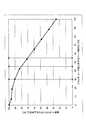
図5は、スライダ・コーナ部(図4の延長領域403、404)を削る割合と磁気ヘッドスライダの浮上特性の関係を示している。図5において、横軸は、スライダ・コーナ部を削る割合(延長領域403、404の面積に対するテーパ部の割合)であり、0%はスライダ・コーナ部を全く削らない場合である。縦軸は、磁気ヘッドスライダ1の浮上特性が劣化する割合であり、100%はスライダ・コーナ部を全く削らない場合の浮上特性である。浮上特性は、スライダ・コーナ部を削った場合の浮上面2で生じる圧力の変化である。ここでいう浮上特性は、浮上量の安定性のことであり、磁気ヘッドスライダ1が量産されたときの個々の浮上量のばらつきを抑えるためのパラメタの変動を想定して計算したものである。尚、レール面13、14へ向かってスライダ・コーナ部51、52を削った場合、空気流の下流となる外周側テーパ部41及び内周側テーパ部42の面積の条件を満たしていれば、外周側テーパ部41及び内周側テーパ部42の形状は、面積の変動に比べて浮上特性へほとんど影響を与えない。 FIG. 5 shows the relationship between the ratio of cutting the slider corner portion (
図に示すように、スライダ・コーナ部を削る割合が増えるにしたがって浮上特性が劣化する。特に、本実施形態の磁気ヘッドスライダ1は、フェムトスライダのため削る割合に対して浮上特性の劣化する割合が大きい。例えば、スライダ・コーナ部51、52を100%(延長領域403、404と同じ面積)削ると、浮上特性は約25%まで低下する。尚、スライダ・コーナ部51、52を100%まで削った場合、スライダ・コーナ部51、52とレール面13、14が接触するが、レール面13、14の形状は変形していない状態となる。 As shown in the figure, the flying characteristics deteriorate as the ratio of cutting the slider / corner portion increases. In particular, the
浮上特性上は、スライダ・コーナ部51、52を削る量がより少ない方が好ましい。一方、ロード時の接触をより防止するためには、スライダ・コーナ部51、52を大きく削った方が好ましい。しかし、浮上特性が悪くなりHDDに搭載した際の調整などが難しくなる。そこで、浮上特性を優先させる場合には、浮上特性の劣化が10%程度で済む様に、スライダ・コーナ部51、52を30%程度まで削ればよい。10%程度の劣化であれば、スライダの個体差やHDDに組み込んだときの公差とほぼ同じ割合で済むので、浮上特性の劣化についてはそれ程考慮せずとも使用する事が出来る。一方、接触防止を優先させる場合には、浮上特性の劣化の傾きが大きくなる手前まで、つまり、浮上特性も20%程度の劣化で済ませる事が出来る範囲である45%程度までスライダ・コーナ部51、52を削ることが出来る。20%程度の劣化であれば、ある程度の調整を行う事により、HDDに搭載可能である。 From the viewpoint of flying characteristics, it is preferable that the amount of cutting the slider / corner portions 51 and 52 is smaller. On the other hand, in order to further prevent contact at the time of loading, it is preferable that the slider / corner portions 51 and 52 are greatly shaved. However, the flying characteristics are deteriorated and adjustment when mounted on the HDD becomes difficult. Therefore, when giving priority to the flying characteristics, the slider / corner portions 51 and 52 may be cut to about 30% so that the flying characteristics can be degraded by about 10%. If the deterioration is about 10%, the difference can be almost the same as the individual difference of the slider and the tolerance when incorporated in the HDD, so that it can be used without much consideration for the deterioration of the flying characteristics. On the other hand, when priority is given to the prevention of contact, the slider / corner portion 51 is up to the point before the slope of the deterioration of the flying characteristics becomes large, that is, up to about 45%, which is the range in which the flying characteristics can be reduced by about 20%. , 52 can be cut. If the deterioration is about 20%, it can be mounted on the HDD by performing some adjustment.
尚、図5は、磁気ヘッドスライダ1をサスペンション101に保持させてアクチュエータ106とともにHDD100に組み付けた場合の公差を、磁気ヘッドスライダ1がロール方向に1度傾斜しているとした場合の浮上特性である。この公差がより少ない場合には、磁気ヘッドスライダ1の傾斜が小さいため浮上特性が向上する。例えば、公差を半分にすれば、浮上特性の劣化具合も半分となる。例えば、磁気ヘッドスライダ1の傾斜が1度の場合、スライダ・コーナ部51、52を70%まで削ると浮上特性比は60%となり40%の劣化となるが、傾斜を0.5度とすれば、劣化を20%と出来るので、使用することが可能となる。 FIG. 5 shows the tolerance when the
尚、上記特許文献3の従来例では、リアパッド近傍まで空気流出端を削っているため、リアパッド上に流れ込む空気流が減少し、リアパッド上のレール面で生じる正圧が減少する。また、負圧溝で発生する負圧も減少することから、スライダの浮上高さを維持するベアリング性能や浮上特性に大きな影響を及ぼすという問題がある。正圧が減少すると、ロード時には、磁気ヘッドスライダの姿勢が安定するまで時間がかかり磁気ディスクに接触する恐れがあり、また、磁気ディスク上で浮上している時でも、外部からの衝撃により磁気ディスクに接触する可能性が高くなってしまう。そこで、本実施形態では、延長領域403、404よりもリアパッド8側(磁気ヘッドスライダの短手方向の中央側)の領域403a、404aの部分までは、外周側テーパ部41及び内周側テーパ部42を設けず、空気流出端4を延長領域403、404よりも中央部側まで削らないことが好ましい。空気流出端4をリアパッド8近傍まで削らないことにより、ベアリング性能の劣化や浮上特性の劣化を防止することができる。 In the conventional example of
また、本実施形態では、ロード時の磁気ヘッドスライダ1と磁気ディスク101との接触を避けるためには、少なくとも空気流出端4の磁気ディスク内周側のスライダ・コーナ部52に、内周側テーパ部42を有していることが好ましい。外周側テーパ部41を設けずに内周側テーパ部42のみを設けた場合でも、ロード時の磁気ヘッドスライダ1と磁気ディスク101との接触を防止することができ、内周側テーパ部42に加えて外周側テーパ部41を設けた場合には、磁気ヘッドスライダ1のバランスを保ち浮上特性の劣化を防止することができる。ここでは内周側テーパ部42のさらに好ましい条件について、図6を用いて説明する。 In the present embodiment, in order to avoid contact between the
図6において、601は、ロード時、磁気ヘッドスライダ1の浮上面2に流れる空気流である。すなわち、ロード時、空気流601は、空気流入端3のディスク外周端5側から空気流出端4のディスク内周端6側へ向かって、ディスク外周端5及びディスク内周端6に対し斜めに流出する。図6において、602は、空気流601の流出方向に内周側レール面14の空気流出端から下流側、つまり内周側レール面14の空気流出端4側及びディスク内周端6側の辺から引いた線であり、ロード時に内周側レール面14の下流(風下)となる部分を示す下流線である。ここでは、この下流線602に対し所定の割合の部分を結ぶ線を境界線603とする。 In FIG. 6, reference numeral 601 denotes an air flow that flows on the
本実施形態では、この境界線603よりもスライダ・コーナ部52側に内周側テーパ部42を形成する。例えば、下流線602に対する境界線603の割合は、50%である。すなわち、内周側テーパ部42は、内周側レール面14から引いた下流線の50%よりも外側に形成されていることが好ましい。尚、図ではレール面を簡略化して四角形としているが、この形状に限らず、図3のような形状でも同様に境界線を引くことができる。先にも述べた通り、レール面13、14或いはサイドステップ軸受け面22、23の流出端側(空気流の下流側)にテーパ部を設けると、発生する圧力が変動してしまう。しかし、実験の結果、レール面13、14或いはサイドステップ軸受け面22、23の最も流出端側からある程度の距離を開ければ、この変動が小さくなる事が分かった。具体的には内周側レール面14から下流に引いた線の50%よりも外側(より下流側)であれば、浮上特性は図5のスライダ・コーナ部51、52を45%程度削る場合と同程度の20%の劣化で済むことが分かった。尚、外周側テーパ部41も同様の割合で削ることができる。 In the present embodiment, the inner peripheral
次に、本実施形態にかかる磁気ヘッドスライダの動作について説明する。図7は、磁気ヘッドスライダ1が磁気ディスク101上に位置している状態を示している。図7(a)は、磁気ディスク101の上から見た図であり、図7(b)は、磁気ディスク101の側面から見た図である。 Next, the operation of the magnetic head slider according to the present embodiment will be described. FIG. 7 shows a state where the
図7(a)、(b)に示されるように、磁気ディスク101上では、磁気ディスク101の回転方向に向かって空気流が発生する。空気流は、磁気ヘッドスライダ1に沿って流れ、浮上面2のレール面11〜15に作用し、磁気ヘッドスライダ1の浮力を発生させる。また、空気流が浮上面2の深溝面31を通過すると、深溝面31に空気流によって負圧が発生する。磁気ヘッドスライダ1は、サスペンション110に設けられたディンプル160によって一点支持されており、レール面11〜15が発生させる浮力と、深溝面31が発生させる負圧とのバランスが磁気ヘッドスライダ1の浮上量や姿勢を決定する。上記のように浮上面2の中央部から空気流出端4側に深溝面31が形成されているため、空気流の上流側で下流側よりも浮上量が大きくなり、磁気ヘッドスライダ1はピッチ角が正の姿勢で浮上する。すなわち、磁気ヘッドスライダ1は、磁気ディスク101上において、スライダ長手方向に対し傾斜しており、空気流入端3よりも空気流出端4の方が低くなるように浮上している。これにより、空気流出端4側にある磁気トランスデューサ10を磁気ディスク面により接近させることができる。 As shown in FIGS. 7A and 7B, an air flow is generated on the
磁気ヘッドスライダ1がこのような姿勢で浮上し、さらにロード時には、ロール方向にディスク内周側がディスク外周側よりも磁気ディスク側に傾く(ロール角が負)となるため、磁気ヘッドスライダ1の空気流入端3よりも空気流出端4が磁気ディスク101へ接触し易い。本実施形態では、空気流出端4側のスライダ・コーナ部52に内周側テーパ部42を設けることにより、ロード時の磁気ヘッドスライダと磁気ディスクとの接触を防止することができる。 The
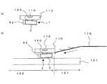
図8(a)は、磁気ディスク上から離れた時のサスペンション先端側から見た磁気ヘッドスライダ1の状態を示している。磁気ディスク上に浮上していない場合、つまり、磁気ヘッドスライダ1に空気流による作用が働いていない場合には、磁気ヘッドスライダ1は、サスペンション110と平行に支持されており、スライダ短手方向に対し水平にバランスしている。 FIG. 8A shows the state of the
図8(b)は、ロード時のサスペンション先端側から見た磁気ヘッドスライダの状態を示している。ロード時、タブ116がランプ115の表面を摺動することで、サスペンション110が磁気ディスク101上へ下降していく。そして、サスペンション110が磁気ディスク101上へ下降するにしたがって、磁気ヘッドスライダ1が磁気ディスク101の表面に近づいていく。磁気ヘッドスライダ1をサスペンション110に取り付ける際のバラツキやねじれにより、ロード時にスライダ短手方向に対し傾斜しながら近づく。 FIG. 8B shows the state of the magnetic head slider as viewed from the front end side of the suspension during loading. During loading, the
図10の従来例では、このとき磁気ヘッドスライダの端部が磁気ディスク面と接触したが、本実施形態では、図8(b)のように、磁気ヘッドスライダ1のスライダ・コーナ部52に内周側テーパ部42を設けたため、磁気ヘッドスライダ1と磁気ディスク101とは接触することがない。したがって、磁気ヘッドスライダの接触を考慮して記録領域を狭くする必要がないため、従来例に比べて、ロード・アンロード領域121を狭くしデータ記録領域122を磁気ディスク外周側へ広くすることができる。 In the conventional example of FIG. 10, the end of the magnetic head slider is in contact with the magnetic disk surface at this time. However, in this embodiment, the slider / corner portion 52 of the
尚、図8の例では、磁気ヘッドスライダが水平となっているが、磁気ヘッドスライダにあらかじめ傾きを持たせてもよい。図9(a)は、磁気ディスク上から離れた時のサスペンション先端側から見た磁気ヘッドスライダの状態を示している。この例では、磁気ヘッドスライダ1は、サスペンション110に対しスライダ短手方向に斜めに支持されており、磁気ディスク外周側が下に磁気ディスク内周側が上になっている。 In the example of FIG. 8, the magnetic head slider is horizontal, but the magnetic head slider may be tilted in advance. FIG. 9A shows the state of the magnetic head slider as viewed from the front end side of the suspension when it is separated from the magnetic disk. In this example, the
図9(b)は、ロード時のサスペンション先端側から見た磁気ヘッドスライダの状態を示している。ロード時、図8(b)と同様に、磁気ヘッドスライダ1が磁気ディスク101に近づくが、図9(b)では、磁気ヘッドスライダ1をディスク内周側が高くなるように傾斜しているため、磁気ヘッドスライダ1と磁気ディスク101が接近する量が抑えられ、磁気ヘッドスライダ1と磁気ディスク101の接触をさらに防止することができる。 FIG. 9B shows the state of the magnetic head slider as viewed from the front end side of the suspension during loading. During loading, the
このように、本実施形態では、磁気ヘッドスライダの空気流出側のスライダ・コーナ部、特に、ディスク内周側のスライダ・コーナ部を削りテーパ部としたことにより、ロード時の磁気ヘッドスライダと磁気ディスクとの接触を防止することができる。したがって、磁気ディスクのロード・アンロード領域を狭くしデータ記録領域を広くすることができる。さらに、テーパ部をレール面及びステップ軸受け面から離間して形成することにより、磁気ヘッドスライダの浮上特性を劣化させることなく磁気ヘッドスライダと磁気ディスクとの接触を防止することができる。レール面の直近にテーパ部を設けるのではなく、テーパ部の面積を空気流出端側の延長領域に対し所定の割合の面積としたり、テーパ部をレール面下流に引いた線対し所定の割合の位置とすることにより、浮上特性への影響をさらに低減することができる。 As described above, in this embodiment, the slider / corner portion on the air outflow side of the magnetic head slider, in particular, the slider / corner portion on the inner circumferential side of the disk is formed into a tapered portion, so that the magnetic head slider and the magnetic head during loading are magnetically Contact with the disk can be prevented. Therefore, the load / unload area of the magnetic disk can be narrowed and the data recording area can be widened. Further, by forming the tapered portion away from the rail surface and the step bearing surface, it is possible to prevent the magnetic head slider from contacting the magnetic disk without deteriorating the flying characteristics of the magnetic head slider. Rather than providing a taper portion in the immediate vicinity of the rail surface, the taper portion has an area of a predetermined ratio with respect to the extended region on the air outflow end side, or a predetermined ratio with respect to a line where the taper portion is drawn downstream of the rail surface. By setting the position, the influence on the flying characteristics can be further reduced.
1 磁気ヘッドスライダ、2 浮上面、3 空気流入端、4 空気流出端、
5 ディスク外周端、6 ディスク内周端、7 フロントパッド、
8 リアパッド、10 磁気トランスデューサ、11,12 流入側レール面、
13 外周側レール面、14 内周側レール面、15 流出側レール面、
16,17 流入パッド、21 フロントステップ軸受け面、
22 外周側軸受け面、23 内周側軸受け面、24 リアステップ軸受け面、
31 深溝面、41,42 テーパ部、
101 磁気ディスク、102 ベース、103 クランプ、
106 アクチュエータ、107 揺動軸、
108 キャリッジ、110 サスペンション、111 アーム、
112 コイル・サポート、113 フラットコイル、
114 上側ステータ・マグネット保持板、115 ランプ、116 タブ、1 magnetic head slider, 2 air bearing surface, 3 air inflow end, 4 air outflow end,
5 disk outer edge, 6 disk inner edge, 7 front pad,
8 Rear pad, 10 Magnetic transducer, 11, 12 Inflow side rail surface,
13 outer peripheral rail surface, 14 inner peripheral rail surface, 15 outflow rail surface,
16, 17 Inflow pad, 21 Front step bearing surface,
22 outer peripheral side bearing surface, 23 inner peripheral side bearing surface, 24 rear step bearing surface,
31 deep groove surface, 41, 42 taper part,
101 magnetic disk, 102 base, 103 clamp,
106 Actuator, 107 Oscillating shaft,
108 Carriage, 110 Suspension, 111 Arm,
112 coil support, 113 flat coil,
114 Upper stator magnet holding plate, 115 lamp, 116 tab,
Claims (15)
Translated fromJapanese前記磁気ヘッドスライダを前記磁気ディスク上からアンロードするランプと、
前記磁気ヘッドスライダを支持するサスペンションを有し前記磁気ヘッドスライダを前記ランプに対しロード・アンロードするアクチュエータと、を備え、
前記磁気ヘッドスライダは、
前記記録ディスクと対向する浮上面の空気流出端側の中央部に、流出側レール面を有するリアパッドと、
前記浮上面の記録ディスク内周側及び記録ディスク外周側に延在し、空気流出端側にサイドレール面を有するフロントパッドと、
前記浮上面に対し垂直なコーナのうち前記空気流出端側の第1のコーナに、前記サイドレール面の最大幅を空気流出端まで延長した延長領域に対し所定の面積を削って形成した第1のテーパ部と、を有する、
磁気ディスク装置。A magnetic head slider having a magnetic transducer for accessing a recording area of a recording disk;
A ramp for unloading the magnetic head slider from the magnetic disk;
An actuator having a suspension for supporting the magnetic head slider and loading / unloading the magnetic head slider with respect to the ramp,
The magnetic head slider is
A rear pad having an outflow rail surface at the center of the air outflow end side of the air bearing surface facing the recording disk;
A front pad extending on the recording disk inner peripheral side and recording disk outer peripheral side of the air bearing surface, and having a side rail surface on the air outflow end side;
Of the corners perpendicular to the air bearing surface, the first corner on the air outflow end side is formed by cutting a predetermined area with respect to an extended region in which the maximum width of the side rail surface is extended to the air outflow end. A taper portion of,
Magnetic disk unit.
請求項1に記載の磁気ディスク装置。The area where the first corner is scraped is an area of less than 70% with respect to the extended region.
The magnetic disk device according to claim 1.
請求項1に記載の磁気ディスク装置。The area where the first corner is scraped is approximately 45% of the extended area.
The magnetic disk device according to claim 1.
請求項1に記載の磁気ディスク装置。The area of scraping off the first corner is an area of less than 30% with respect to the extended region.
The magnetic disk device according to claim 1.
請求項1に記載の磁気ディスク装置。The first tapered portion is formed away from the side rail surface and by removing a region on the outflow side rail surface side from the side rail surface.
The magnetic disk device according to claim 1.
請求項1に記載の磁気ディスク装置。The first taper portion is formed at a corner on the inner peripheral side of the recording disk among the corners on the air outflow end side of the magnetic head slider.
The magnetic disk device according to claim 1.
請求項7に記載の磁気ディスク装置。The first taper portion is formed away from the side rail surface on the inner peripheral side of the magnetic disk.
The magnetic disk device according to claim 7.
前記第1のテーパ部は、前記サイドステップ軸受け面から離間して形成されている、
請求項1に記載の磁気ディスク装置。The front pad further includes a side step bearing surface formed through a step from the side rail surface,
The first tapered portion is formed away from the side step bearing surface.
The magnetic disk device according to claim 1.
請求項1に記載の磁気ディスク装置。The first tapered portion is formed so as to avoid the side rail surface when viewed from the air bearing surface side.
The magnetic disk device according to claim 1.
請求項1に記載の磁気ディスク装置。The first tapered portion is formed outside a line drawn so as to be in contact with the side rail surface corresponding to a skew angle.
The magnetic disk device according to claim 1.
前記第1のテーパ部は、前記負圧発生面から前記浮上面の反対側の面に向かって形成されている、
請求項1に記載の磁気ディスク装置。The magnetic head slider has a negative pressure generating surface that generates a negative pressure on the air bearing surface,
The first tapered portion is formed from the negative pressure generating surface toward a surface opposite to the air bearing surface.
The magnetic disk device according to claim 1.
請求項6に記載の磁気ディスク装置。The magnetic head slider further has a second taper portion at a second corner on the outer peripheral side of the recording disk among the corners on the air outflow end side of the magnetic head slider.
The magnetic disk device according to claim 6.
請求項12に記載の磁気ディスク装置。The second tapered portion is formed away from the side rail surface on the outer peripheral side of the magnetic disk.
The magnetic disk device according to claim 12.
前記磁気ヘッドスライダを前記磁気ディスク上からアンロードするランプと、
前記磁気ヘッドスライダを支持するサスペンションを有し前記磁気ヘッドスライダを前記ランプに対しロード・アンロードするアクチュエータと、を備え、
前記磁気ヘッドスライダは、
前記記録ディスクと対向する浮上面の空気流入端側に設けられたフロントパッドと、
このフロントバッドの前記記録ディスク内周側を延伸する内周側サイドステップ軸受け面と、
この内周側サイドステップ軸受け面上に設けられ、前記記録ディスク側に突出した内周側サイドレール面と、
この内周側サイドレール面の空気流出端からロード時の空気流出方向に延びる線のほぼ50%となる位置よりも前記空気流出方向側にのみ前記浮上面を垂直に除去して設けられたテーパ部とを有する、
磁気ディスク装置。A magnetic head slider having a magnetic transducer for accessing a recording area of a recording disk;
A ramp for unloading the magnetic head slider from the magnetic disk;
An actuator having a suspension for supporting the magnetic head slider and loading / unloading the magnetic head slider with respect to the ramp,
The magnetic head slider is
A front pad provided on the air inflow end side of the air bearing surface facing the recording disk;
An inner peripheral side step bearing surface extending the inner peripheral side of the recording disk of the front pad;
An inner peripheral side rail surface provided on the inner peripheral side step bearing surface and projecting toward the recording disk;
A taper provided by removing the air bearing surface vertically only on the air outflow direction side from a position that is approximately 50% of a line extending in the air outflow direction at the time of loading from the air outflow end of the inner peripheral side rail surface. Having a part,
Magnetic disk unit.
前記磁気ヘッドスライダを前記磁気ディスク上からアンロードするためのランプと、
前記磁気ヘッドスライダを支持するサスペンションを有し前記磁気ヘッドスライダを移動させるアクチュエータと、を備える、
磁気ディスク装置。
A magnetic transducer for accessing a recording area of the recording disk, an ABS surface provided on the air bearing surface facing the recording disk, and a region where the ABS surface is removed from an air outflow end side corner perpendicular to the air bearing surface. A magnetic head slider having a chamfer,
A ramp for unloading the magnetic head slider from the magnetic disk;
An actuator having a suspension for supporting the magnetic head slider and moving the magnetic head slider;
Magnetic disk unit.
Priority Applications (2)
| Application Number | Priority Date | Filing Date | Title |
|---|---|---|---|
| JP2005306462AJP2007115352A (en) | 2005-10-20 | 2005-10-20 | Magnetic disk device |
| US11/584,380US20070091506A1 (en) | 2005-10-20 | 2006-10-19 | Magnetic disk drive with air bearing surface design for data area expansion |
Applications Claiming Priority (1)
| Application Number | Priority Date | Filing Date | Title |
|---|---|---|---|
| JP2005306462AJP2007115352A (en) | 2005-10-20 | 2005-10-20 | Magnetic disk device |
Publications (1)
| Publication Number | Publication Date |
|---|---|
| JP2007115352Atrue JP2007115352A (en) | 2007-05-10 |
Family
ID=37985102
Family Applications (1)
| Application Number | Title | Priority Date | Filing Date |
|---|---|---|---|
| JP2005306462APendingJP2007115352A (en) | 2005-10-20 | 2005-10-20 | Magnetic disk device |
Country Status (2)
| Country | Link |
|---|---|
| US (1) | US20070091506A1 (en) |
| JP (1) | JP2007115352A (en) |
Cited By (1)
| Publication number | Priority date | Publication date | Assignee | Title |
|---|---|---|---|---|
| JP2011123949A (en)* | 2009-12-10 | 2011-06-23 | Hitachi Global Storage Technologies Netherlands Bv | Magnetic head slider and magnetic disk device |
Families Citing this family (5)
| Publication number | Priority date | Publication date | Assignee | Title |
|---|---|---|---|---|
| JP2006004539A (en)* | 2004-06-18 | 2006-01-05 | Hitachi Global Storage Technologies Netherlands Bv | Slider and rotating disk storage device |
| JP4476970B2 (en)* | 2006-06-30 | 2010-06-09 | 株式会社東芝 | Head, head suspension assembly, and disk device including the same |
| US20090109574A1 (en)* | 2007-10-26 | 2009-04-30 | Seagate Technology Llc | High acceleration seek optimized slider |
| JP2010049744A (en)* | 2008-08-21 | 2010-03-04 | Toshiba Storage Device Corp | Head slider, magnetic head slider and magnetic storage device |
| US7961432B2 (en)* | 2008-12-12 | 2011-06-14 | Kabushiki Kaisha Toshiba | Head, head suspension assembly, and disk drive provided with the same |
Family Cites Families (4)
| Publication number | Priority date | Publication date | Assignee | Title |
|---|---|---|---|---|
| KR100276578B1 (en)* | 1996-10-28 | 2000-12-15 | 니시무로 타이죠 | Head slider and recording / playback apparatus using the same |
| US6311388B1 (en)* | 1997-09-22 | 2001-11-06 | Seagate Technology, Inc. | Method of making air bearing with corner steps |
| US6525909B1 (en)* | 2000-04-27 | 2003-02-25 | Seagate Technology Llc | Disc head slider having deeply recessed corners |
| US7433155B2 (en)* | 2004-12-01 | 2008-10-07 | Seagate Technology Llc | Slider having recessed corner features |
- 2005
- 2005-10-20JPJP2005306462Apatent/JP2007115352A/enactivePending
- 2006
- 2006-10-19USUS11/584,380patent/US20070091506A1/ennot_activeAbandoned
Cited By (1)
| Publication number | Priority date | Publication date | Assignee | Title |
|---|---|---|---|---|
| JP2011123949A (en)* | 2009-12-10 | 2011-06-23 | Hitachi Global Storage Technologies Netherlands Bv | Magnetic head slider and magnetic disk device |
Also Published As
| Publication number | Publication date |
|---|---|
| US20070091506A1 (en) | 2007-04-26 |
Similar Documents
| Publication | Publication Date | Title |
|---|---|---|
| JP4377947B1 (en) | Head, head suspension assembly, and disk device including the same | |
| US7564650B2 (en) | Head apparatus having a slider with first and second positive pressure parts and a negative pressure part and disc drive having the same | |
| JP5060634B1 (en) | Head, head gimbal assembly including the head, and disk device | |
| JP4476970B2 (en) | Head, head suspension assembly, and disk device including the same | |
| US8264794B2 (en) | Head and disk drive with same | |
| CN1716389A (en) | Floating block and rotating disk type storage devices | |
| JP2006302452A (en) | Head, head suspension assembly, and disk device including the same | |
| JP4247290B1 (en) | Head, head suspension assembly, and disk device including the same | |
| US20050036241A1 (en) | Rotary disk storage device and method | |
| US20070091506A1 (en) | Magnetic disk drive with air bearing surface design for data area expansion | |
| US8339730B2 (en) | Two-step recess base | |
| JP4818090B2 (en) | Head, head suspension assembly, and disk device including the same | |
| US7787218B2 (en) | Data storage device | |
| US7573671B2 (en) | Disk device with reduced flutter | |
| JP2008016069A (en) | Head, head suspension assembly, and disk device including the same | |
| US7576945B2 (en) | Disk drive with an air flow passage within enclosure to reduce flutter | |
| JP4074265B2 (en) | Head suspension assembly and disk drive equipped with the same | |
| JP2006179148A (en) | Disk drive device | |
| JP2007242085A (en) | Data storage device and disk drive device | |
| JP2006185486A (en) | Disk unit | |
| JP2006120198A (en) | Head, head suspension assembly, and disk device including the same | |
| JP2004234804A (en) | Disk device and head suspension assembly | |
| JP4834762B2 (en) | Head, head suspension assembly, and disk device including the same | |
| KR100660906B1 (en) | Head Slider and Hard Disk Drive with the Same | |
| CN117727344A (en) | Disk device |