JP2007105481A - Surgical stapling device - Google Patents
Surgical stapling deviceDownload PDFInfo
- Publication number
- JP2007105481A JP2007105481AJP2006280546AJP2006280546AJP2007105481AJP 2007105481 AJP2007105481 AJP 2007105481AJP 2006280546 AJP2006280546 AJP 2006280546AJP 2006280546 AJP2006280546 AJP 2006280546AJP 2007105481 AJP2007105481 AJP 2007105481A
- Authority
- JP
- Japan
- Prior art keywords
- assembly
- body portion
- distal end
- proximal
- loading unit
- Prior art date
- Legal status (The legal status is an assumption and is not a legal conclusion. Google has not performed a legal analysis and makes no representation as to the accuracy of the status listed.)
- Withdrawn
Links
Images


Classifications
- A—HUMAN NECESSITIES
- A61—MEDICAL OR VETERINARY SCIENCE; HYGIENE
- A61B—DIAGNOSIS; SURGERY; IDENTIFICATION
- A61B17/00—Surgical instruments, devices or methods
- A61B17/068—Surgical staplers, e.g. containing multiple staples or clamps
- A61B17/072—Surgical staplers, e.g. containing multiple staples or clamps for applying a row of staples in a single action, e.g. the staples being applied simultaneously
- A61B17/07207—Surgical staplers, e.g. containing multiple staples or clamps for applying a row of staples in a single action, e.g. the staples being applied simultaneously the staples being applied sequentially
- A—HUMAN NECESSITIES
- A61—MEDICAL OR VETERINARY SCIENCE; HYGIENE
- A61B—DIAGNOSIS; SURGERY; IDENTIFICATION
- A61B17/00—Surgical instruments, devices or methods
- A61B17/068—Surgical staplers, e.g. containing multiple staples or clamps
- A61B17/0682—Surgical staplers, e.g. containing multiple staples or clamps for applying U-shaped staples or clamps, e.g. without a forming anvil
- A61B17/0684—Surgical staplers, e.g. containing multiple staples or clamps for applying U-shaped staples or clamps, e.g. without a forming anvil having a forming anvil staying above the tissue during stapling
- A—HUMAN NECESSITIES
- A61—MEDICAL OR VETERINARY SCIENCE; HYGIENE
- A61B—DIAGNOSIS; SURGERY; IDENTIFICATION
- A61B17/00—Surgical instruments, devices or methods
- A61B2017/0023—Surgical instruments, devices or methods disposable
- A—HUMAN NECESSITIES
- A61—MEDICAL OR VETERINARY SCIENCE; HYGIENE
- A61B—DIAGNOSIS; SURGERY; IDENTIFICATION
- A61B17/00—Surgical instruments, devices or methods
- A61B17/00234—Surgical instruments, devices or methods for minimally invasive surgery
- A61B2017/00292—Surgical instruments, devices or methods for minimally invasive surgery mounted on or guided by flexible, e.g. catheter-like, means
- A61B2017/003—Steerable
- A—HUMAN NECESSITIES
- A61—MEDICAL OR VETERINARY SCIENCE; HYGIENE
- A61B—DIAGNOSIS; SURGERY; IDENTIFICATION
- A61B17/00—Surgical instruments, devices or methods
- A61B2017/0046—Surgical instruments, devices or methods with a releasable handle; with handle and operating part separable
- A—HUMAN NECESSITIES
- A61—MEDICAL OR VETERINARY SCIENCE; HYGIENE
- A61B—DIAGNOSIS; SURGERY; IDENTIFICATION
- A61B17/00—Surgical instruments, devices or methods
- A61B2017/0046—Surgical instruments, devices or methods with a releasable handle; with handle and operating part separable
- A61B2017/00473—Distal part, e.g. tip or head
- A—HUMAN NECESSITIES
- A61—MEDICAL OR VETERINARY SCIENCE; HYGIENE
- A61B—DIAGNOSIS; SURGERY; IDENTIFICATION
- A61B17/00—Surgical instruments, devices or methods
- A61B2017/00477—Coupling
- A—HUMAN NECESSITIES
- A61—MEDICAL OR VETERINARY SCIENCE; HYGIENE
- A61B—DIAGNOSIS; SURGERY; IDENTIFICATION
- A61B17/00—Surgical instruments, devices or methods
- A61B17/28—Surgical forceps
- A61B17/29—Forceps for use in minimally invasive surgery
- A61B2017/2901—Details of shaft
- A61B2017/2902—Details of shaft characterized by features of the actuating rod
- A—HUMAN NECESSITIES
- A61—MEDICAL OR VETERINARY SCIENCE; HYGIENE
- A61B—DIAGNOSIS; SURGERY; IDENTIFICATION
- A61B17/00—Surgical instruments, devices or methods
- A61B17/28—Surgical forceps
- A61B17/29—Forceps for use in minimally invasive surgery
- A61B2017/2901—Details of shaft
- A61B2017/2905—Details of shaft flexible
- A—HUMAN NECESSITIES
- A61—MEDICAL OR VETERINARY SCIENCE; HYGIENE
- A61B—DIAGNOSIS; SURGERY; IDENTIFICATION
- A61B17/00—Surgical instruments, devices or methods
- A61B17/28—Surgical forceps
- A61B17/29—Forceps for use in minimally invasive surgery
- A61B2017/2926—Details of heads or jaws
- A61B2017/2931—Details of heads or jaws with releasable head
- A—HUMAN NECESSITIES
- A61—MEDICAL OR VETERINARY SCIENCE; HYGIENE
- A61B—DIAGNOSIS; SURGERY; IDENTIFICATION
- A61B17/00—Surgical instruments, devices or methods
- A61B17/28—Surgical forceps
- A61B17/29—Forceps for use in minimally invasive surgery
- A61B2017/2947—Pivots
Landscapes
- Health & Medical Sciences (AREA)
- Life Sciences & Earth Sciences (AREA)
- Surgery (AREA)
- Heart & Thoracic Surgery (AREA)
- Engineering & Computer Science (AREA)
- Biomedical Technology (AREA)
- Nuclear Medicine, Radiotherapy & Molecular Imaging (AREA)
- Medical Informatics (AREA)
- Molecular Biology (AREA)
- Animal Behavior & Ethology (AREA)
- General Health & Medical Sciences (AREA)
- Public Health (AREA)
- Veterinary Medicine (AREA)
- Surgical Instruments (AREA)
Abstract
Description
Translated fromJapanese本願は、米国仮出願番号60/726,546(「’546号出願」、2005年10月14日出願、発明の名称「Surgical Stapling Device」)の優先権を主張する。’546号出願の全内容は、本明細書中に参考として援用される。 This application claims priority to US Provisional Application No. 60 / 726,546 (“'546 Application”, filed Oct. 14, 2005, Title of Invention “Surgical Stapling Device”). The entire contents of the '546 application are incorporated herein by reference.
(背景)
(1.技術分野)
本願は、組織にステープルを適用するための外科手術用ステープリングデバイスに関する。より具体的には、本願は、工具部材を備える単回使用装填ユニット(「SULU」)を有する外科手術用ステープリングデバイスに関する。この工具部材は、ステープルの直線状の列を組織に適用し、そして同時に、これらのステープルの直線状の列の間で組織を切断するためのものである。(background)
(1. Technical field)
The present application relates to a surgical stapling device for applying staples to tissue. More specifically, the present application relates to a surgical stapling device having a single use loading unit (“SULU”) comprising a tool member. The tool member is for applying a linear row of staples to tissue and simultaneously cutting tissue between the linear rows of staples.
(2.関連技術の背景)
工具アセンブリの対向する顎構造体の間に組織を把持するか、またはクランプし、その後、このクランプされた組織を固定するための、外科手術用デバイスは、当該分野において周知である。これらのデバイスは、固定された組織を切開するためのナイフを備え得る。これらのファスナーは、代表的に、外科手術用ステープルの形態であるが、外科手術の用途のために適切な材料から形成される2部品ファスナーもまた、周知である。(2. Background of related technology)
Surgical devices for grasping or clamping tissue between opposing jaw structures of a tool assembly and subsequently fixing the clamped tissue are well known in the art. These devices may include a knife for incising the fixed tissue. These fasteners are typically in the form of surgical staples, but two-part fasteners formed from materials suitable for surgical applications are also well known.
代表的に、工具部材は、ステープルカートリッジおよびアンビルを備え、このステープルカートリッジは、横方向に間隔を空けた、少なくとも2つの列に整列された複数のステープルを収容し、そしてこのアンビルは、これらのステープルがこのカートリッジから駆動される際に、これらのステープルのステープルレッグを受容して形作るための、複数のステープル形成ポケットを備える。一般に、このステープリング作動は、駆動部材によってなされる。この駆動部材は、カムウェッジを、このステープルカートリッジを通して長手軸方向に進め、これらのカムウェッジは、ステープルプッシャーに作用して、これらのステープルをこのステープルカートリッジから連続的に排出する。ナイフは、ステープルの列の間を移動して、これらのステープルの列の間の組織を長手軸方向に切断し得、そして/またはステープルされた組織を開き得る。 Typically, the tool member comprises a staple cartridge and an anvil, the staple cartridge containing a plurality of laterally spaced staples aligned in at least two rows, and the anvil comprises these A plurality of staple forming pockets are provided for receiving and shaping the staple legs of the staples as the staples are driven from the cartridge. In general, this stapling operation is performed by a drive member. The drive member advances a cam wedge longitudinally through the staple cartridge, and the cam wedge acts on a staple pusher to continuously eject the staples from the staple cartridge. The knife may move between the staple rows to cut longitudinally the tissue between the staple rows and / or open the stapled tissue.
腹腔鏡外科手術手順および/または内視鏡外科手術手順において、外科手術手順は、小さい切開を通してか、または患者に作製された小さい侵入口を通して実施される。従来の手順または開胸手順において、外科医は、手術部位に直接アクセスする。患者の減少した外傷、患者の短い回復期間および全体の費用のかなりの減少に起因して、内視鏡手順は、開胸手順より好ましい。内視鏡外科手術手順および/または腹腔鏡外科手術手順の特別な必要性を検討するために、手術部位へのより容易なアクセスを外科医に提供する、内視鏡外科手術ステープリングデバイスが開発されている。代表的に、これらのステープリングデバイスは、関節運動可能な工具部材を備え、この工具部材は、このステープリングデバイスの遠位端に隣接して支持される。この工具部材は、外科医が制限された空間内で工具アセンブリを操作することを可能にするように、選択的に操作され得る。 In laparoscopic and / or endoscopic surgical procedures, the surgical procedure is performed through a small incision or through a small entry made in the patient. In conventional or thoracotomy procedures, the surgeon has direct access to the surgical site. The endoscopic procedure is preferred over the thoracotomy procedure due to the patient's reduced trauma, the patient's short recovery period and the significant reduction in overall costs. An endoscopic surgical stapling device has been developed that provides surgeons with easier access to the surgical site to address the special needs of endoscopic and / or laparoscopic surgical procedures. ing. Typically, these stapling devices comprise an articulatable tool member that is supported adjacent to the distal end of the stapling device. The tool member can be selectively manipulated to allow the surgeon to manipulate the tool assembly in a limited space.
Tyco Healthcare Group,LPは、関節運動可能な内視鏡ステープリング器具(例えば、MULTIFIRE ENDO GIA*30およびMULTIFIRE ENDO GIA*60)を、数年間にわたり製造し、そして販売している。これらの器具は、使い捨ての装填ユニット(「DLU」)または単回使用の装填ユニット(「SULU」)を備え、これらの装填ユニットは、工具アセンブリ、近位本体部分および設置アセンブリを備える。この設置アセンブリは、この工具アセンブリを、この近位本体部分に固定するためのものである。これらの器具は、内視鏡手術の分野において、かなりの臨床利益を提供している。それにもかかわらず、製造の費用および複雑さを減少させる改善が、当該分野において望ましい。Tyco Healthcare Group, LP has manufactured and sold articulatable endoscopic stapling instruments (eg, MULTIFIRE ENDO GIA* 30 and MULTIFIIRE ENDO GIA* 60) for several years. These instruments comprise a disposable loading unit (“DLU”) or a single use loading unit (“SULU”), which comprises a tool assembly, a proximal body portion and an installation assembly. The installation assembly is for securing the tool assembly to the proximal body portion. These instruments offer considerable clinical benefits in the field of endoscopic surgery. Nevertheless, improvements that reduce manufacturing costs and complexity are desirable in the art.
既存の器具に対して改善または改変を行う際に、他の市販の製品と比較して、MULTIFIRE ENDO GIA*30器具およびMULTIFIRE ENDO GIA*60器具の重要な利点のいずれも犠牲にしないことが、非常に望ましい。例えば、あらゆる改善は、その器具の各発射のために新たなナイフ刃を有利には提供するべきであり、そして複数のサイズの使い捨て装填ユニット(「DLU」)と共にこの器具が作動することを可能にするべきである。When making improvements or modifications to existing instruments, it does not sacrifice any of the important advantages of the MULTIFIIRE ENDO GIA* 30 instrument and the MULTIFIRE ENDO GIA* 60 instrument compared to other commercially available products, Highly desirable. For example, any improvement should advantageously provide a new knife blade for each launch of the instrument and allow the instrument to work with multiple sizes of disposable loading units ("DLU") Should be.
本発明は、以下を提供する:
(項目1)
外科手術用デバイスであって、以下:
近位端および遠位端を有する本体部分であって、該本体部分は、長手軸方向のボアを規定し、該本体部分の遠位端は、少なくとも1つのチャネルを規定する内壁を備える、本体部分;ならびに
近位本体部分および遠位工具アセンブリを有する使い捨て装填ユニットであって、該近位本体部分は、該本体部分の遠位端の内部に受容されるような寸法の挿入先端を備え、該挿入先端は、該挿入先端に形成された少なくとも1つの突起を有し、該少なくとも1つの突起の各々は、該少なくとも1つのチャネルのうちの1つの内部にスライド可能に受容されるような寸法である、使い捨て装填ユニット、
を備え、
該少なくとも1つのチャネルを規定する該内壁の遠位端は、該突起の1つ以上を該少なくとも1つのチャネル内に案内し、そして該使い捨て装填ユニットを該本体部分と適切に整列させるように、角度を付けられている、外科手術用デバイス。The present invention provides the following:
(Item 1)
Surgical device, the following:
A body portion having a proximal end and a distal end, the body portion defining a longitudinal bore, the distal end of the body portion comprising an inner wall defining at least one channel. A disposable loading unit having a proximal body portion and a distal tool assembly, the proximal body portion comprising an insertion tip dimensioned to be received within the distal end of the body portion; The insertion tip has at least one projection formed on the insertion tip, each of the at least one projection being dimensionally slidably received within one of the at least one channel. A disposable loading unit,
With
A distal end of the inner wall defining the at least one channel guides one or more of the protrusions into the at least one channel and properly aligns the disposable loading unit with the body portion; An angled surgical device.
(項目2)
上記少なくとも1つの突起が、2つの突起を備え、そして上記少なくとも1つのチャネルが、2つのチャネルを備える、項目1に記載の外科手術用デバイス。(Item 2)
The surgical device according to
(項目3)
上記少なくとも1つのチャネルの各々を規定している上記内壁の角度の付いた遠位端が、60°以上の角度を規定する、項目1に記載の外科手術用デバイス。(Item 3)
The surgical device of
(項目4)
上記工具アセンブリが、カートリッジアセンブリおよびアンビルアセンブリを備える、項目1に記載の外科手術用デバイス。(Item 4)
The surgical device of
(項目5)
上記カートリッジアセンブリが、複数のステープルを備える、項目4に記載の外科手術用デバイス。(Item 5)
The surgical device of
(項目6)
ハンドルアセンブリをさらに備える、項目1に記載の外科手術用デバイスであって、上記本体部分が、該ハンドルアセンブリに支持され、そして該ハンドルアセンブリから遠位に延びる、外科手術用デバイス。(Item 6)
The surgical device of
(項目7)
上記ハンドルアセンブリが、静止ハンドル部材、可動トリガ、およびバレル部分を備える、項目6に記載の外科手術用デバイス。(Item 7)
The surgical device of claim 6, wherein the handle assembly comprises a stationary handle member, a movable trigger, and a barrel portion.
(項目8)
上記バレル部分に支持された回転可能な部材をさらに備える、項目7に記載の外科手術用デバイスであって、上記本体部分が、該回転可能な部材に支持され、そして上記ハンドルアセンブリに対して、該回転可能な部材と一緒に回転可能である、外科手術用デバイス。(Item 8)
The surgical device of claim 7, further comprising a rotatable member supported on the barrel portion, wherein the body portion is supported on the rotatable member and with respect to the handle assembly; A surgical device that is rotatable with the rotatable member.
(項目9)
上記使い捨て装填ユニットが、上記近位本体部分と上記工具アセンブリとの間に位置する設置部分をさらに備え、該設置部分が、該工具アセンブリを、該近位本体部分に旋回式に固定する、項目1に記載の外科手術用デバイス。(Item 9)
The disposable loading unit further comprises an installation portion positioned between the proximal body portion and the tool assembly, the installation portion pivotally securing the tool assembly to the proximal body portion. The surgical device according to
(項目10)
上記工具アセンブリが、カートリッジアセンブリおよびアンビルアセンブリを備える、項目9に記載の外科手術用デバイス。(Item 10)
The surgical device of
複数のファスナーを身体組織に連続的に適用し、そして同時に組織を切開するための、外科手術用ステープリングデバイスが提供される。この外科手術用ステープリングデバイスは、細長本体を備え、この細長本体は、単回使用の装填ユニット(「SULU」)または使い捨て装填ユニット(「DLU」)を受容するように適合されている、これらの装填ユニットは、直線状の列の形態でステープルを有し、この直線状の列の長さは、約30mmと60mmとの間であり得る。各DLUは、近位本体部分、設置アセンブリ、および工具アセンブリを備える。この近位本体部分は、1つ以上の突起を有する近位端を有し、これらの突起は、細長本体の遠位端に形成された1つ以上のチャネル内に受容されるような寸法である。これらのチャネルを規定する壁の遠位端は、面取りされ得るか、または角度を付けられ得、その結果、このDLUの近位端がこの細長本体の遠位端に挿入される際にこのDLUが細長本体と適切に整列しない場合に、これらのチャネルを規定する壁の面取りされたかまたは角度の付いた遠位端は、上記突起とカム作用して、このDLUをこの細長本体と適切に整列させる。 A surgical stapling device is provided for sequentially applying a plurality of fasteners to body tissue and simultaneously incising the tissue. The surgical stapling device comprises an elongate body that is adapted to receive a single use loading unit ("SULU") or a disposable loading unit ("DLU"). The loading unit has staples in the form of straight rows, the length of which can be between about 30 mm and 60 mm. Each DLU includes a proximal body portion, an installation assembly, and a tool assembly. The proximal body portion has a proximal end having one or more protrusions that are dimensioned to be received within one or more channels formed at the distal end of the elongated body. is there. The distal ends of the walls defining these channels can be chamfered or angled so that the DLU's proximal end is inserted into the elongate body's distal end as the DLU is inserted. The chamfered or angled distal ends of the walls defining these channels will cam with the projections to properly align the DLU with the elongate body when the is not properly aligned with the elongate body. Let
(要旨)
近位端と遠位端とを有し、そして長手軸方向ボアを規定する本体部分を備える、外科手術用デバイスが、提供される。この本体部分の遠位端は、少なくとも1つのチャネルを規定する内壁を有する。使い捨て装填ユニットがまた提供され、この装填ユニットは、近位本体部分および遠位工具アセンブリを備える。この近位本体部分は、本体部分の遠位端の内部に受容されるような寸法にされた挿入先端を備える。この挿入先端には、少なくとも1つの突起が形成される。少なくとも1つの突起の各々は、少なくとも1つのチャネルの対の1つの内部にスライド可能に受容されるような寸法にされる。少なくとも1つのチャネルを規定する内壁の遠位端は、1つ以上の突起を1つ以上のチャネル内に案内し、そして使い捨て装填ユニットを本体部分と適切に整列させるために、角度を付けられる。1つの実施形態において、少なくとも1つの突起は、2つの突起を備え、そして少なくとも1つのチャネルは、2つのチャネルを備える。少なくとも1つのチャネルの各々を規定する内壁の、角度の付いた遠位端は、60°以上の角度を規定する。1つの実施形態において、工具アセンブリは、カートリッジアセンブリおよびアンビルアセンブリを備える。このカートリッジアセンブリは、複数のステープルを備える。このデバイスは、ハンドルアセンブリを備え得、本体部分は、このハンドルアセンブリに支持され、そしてこのハンドルアセンブリから遠位に延びる。このハンドルアセンブリは、静止ハンドル部材、可動トリガ、およびバレル部分を備え得る。1つの実施形態において、回転可能な部材が、このバレル部分に支持され、そして本体部分は、この回転可能な部材に支持され、そしてこの回転可能な部材と一緒に、ハンドルアセンブリに対して回転可能である。1つの実施形態において、使い捨て装填ユニットは、設置部分をさらに備え、この設置部分は、近位本体部分と工具アセンブリとの間に位置決めされる。この設置部分は、この工具アセンブリを、近位本体部分に旋回式に固定する。(Summary)
A surgical device is provided having a body portion having a proximal end and a distal end and defining a longitudinal bore. The distal end of the body portion has an inner wall that defines at least one channel. A disposable loading unit is also provided, the loading unit comprising a proximal body portion and a distal tool assembly. The proximal body portion includes an insertion tip dimensioned to be received within the distal end of the body portion. At least one protrusion is formed at the insertion tip. Each of the at least one protrusion is dimensioned to be slidably received within one of the at least one channel pair. The distal end of the inner wall defining the at least one channel is angled to guide the one or more protrusions into the one or more channels and to properly align the disposable loading unit with the body portion. In one embodiment, the at least one protrusion comprises two protrusions and the at least one channel comprises two channels. The angled distal end of the inner wall defining each of the at least one channel defines an angle of 60 ° or greater. In one embodiment, the tool assembly comprises a cartridge assembly and an anvil assembly. The cartridge assembly includes a plurality of staples. The device may comprise a handle assembly, the body portion being supported by the handle assembly and extending distally from the handle assembly. The handle assembly can include a stationary handle member, a movable trigger, and a barrel portion. In one embodiment, a rotatable member is supported on the barrel portion and the body portion is supported on the rotatable member and is rotatable with the rotatable member relative to the handle assembly. It is. In one embodiment, the disposable loading unit further comprises an installation portion that is positioned between the proximal body portion and the tool assembly. The installation portion pivotally secures the tool assembly to the proximal body portion.
本発明により、既存の器具の重要な利点のいずれも犠牲にしない、外科手術用ステープリングデバイスが提供される。 The present invention provides a surgical stapling device that does not sacrifice any of the important advantages of existing instruments.
本開示の外科手術用ステープリングデバイスの種々の実施形態が、図面を参照して本明細書中に記載される。 Various embodiments of the surgical stapling device of the present disclosure are described herein with reference to the drawings.
(実施形態の詳細な説明)
本開示の外科手術用ステープリングデバイスの実施形態が、図面を参照してここで詳細に記載される。図面において、同じ参照番号は、いくつかの図の各々において、同一の要素または対応する要素を指定する。(Detailed description of embodiment)
Embodiments of the presently disclosed surgical stapling device will now be described in detail with reference to the drawings. In the drawings, like reference numbers designate identical or corresponding elements in each of the several views.
以下の説明において、用語「近位」は、伝統的であるように、ステープリングデバイスの、操作者に最も近い端部をいい、一方で、用語「遠位」は、このデバイスの、操作者から最も遠い端部をいう。 In the following description, the term “proximal” refers to the end of the stapling device closest to the operator, as is traditional, while the term “distal” refers to the operator of this device. The end farthest from.
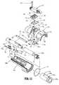
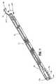
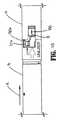
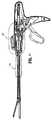
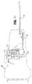
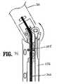
図1〜4は、一般的に10として示される、本開示の外科手術用ステープリングデバイスの1つの実施形態を図示する。簡単に言えば、外科手術用ステープリングデバイス10は、ハンドルアセンブリ12および細長本体14を備える。図1および図2に図示されるように、細長本体14の長さは、特定の外科手術手順に適合するように、変動し得る。使い捨て装填ユニット、すなわちDLU 16は、細長本体14の遠位端に解放可能に固定される。DLU 16は、近位本体部分18(これは、細長本体14の延長部を形成する)および遠位工具アセンブリ20(これは、カートリッジアセンブリ22およびアンビルアセンブリ24を備える)を備える。工具アセンブリ20は、細長本体14の長手方向軸に対して実質的に垂直な軸の周りで、本体18に旋回可能に接続される。カートリッジアセンブリ22は、複数のステープルを収容する。アンビルアセンブリ24は、カートリッジアセンブリ22に対して、カートリッジアセンブリ22から間隔を空けた開位置と、カートリッジアセンブリ24と併置して整列した接近位置またはクランプ位置との間で、可動である。1つの実施形態において、これらのステープルは、約30mm〜約60mmの長さを有する直線状のステープル列を適用するように、カートリッジアセンブリ22に収容されるが、他のステープルの構成および長さが、予測される。あるいは、他のステープルラインの構成が、提供され得る。 1-4 illustrate one embodiment of the presently disclosed surgical stapling device, generally indicated as 10. Briefly, the
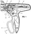
ハンドルアセンブリ12は、静止ハンドル部材26、可動ハンドルまたはトリガ28、およびバレル部分30を備える。回転可能な部材32が、バレル部分30の前端に回転可能に設置され、そして細長本体14に固定されて、ハンドルアセンブリ12に対する細長本体14の回転を容易にする。関節運動レバー122が、バレル部分30の遠位部分に支持され、そして本明細書中で以下に記載される様式で作動して、DLU 16の本体部分18に対する工具アセンブリ20の関節運動を引き起こす。1対の戻しノブ36が、バレル部分30に沿って可動に支持され、以下に詳細に記載されるような、外科手術用ステープリングデバイス10の、進められた位置から引き込まれた位置への運動を引き起こす。 Handle
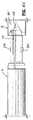
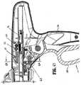
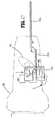
図5〜図8を参照すると、ハンドルアセンブリ12は、ハウジング38を備え、このハウジング38は、プラスチックで成型されたハウジング半セクション38aおよび38bから形成され得る。あるいは、他の材料が、ハウジングを形成するために使用され得、これらの材料としては、金属(例えば、ステンレス鋼)が挙げられる。ハウジング38は、ハンドルアセンブリ12の、静止ハンドル26およびバレル部分30を形成する(図1を参照のこと)。可動ハンドル28は、ハウジング半セクション38aと38bとの間で、円筒形部材40の周りに回転可能に支持される。この円筒形部材40は、可動ハンドル28の開口部41の内部に受容される。付勢部材42(これは、好ましくは、ねじりばねである)は、可動ハンドル28を、静止ハンドル26から離れる方向に、非圧縮位置へと推進する。可動ハンドル28は、1対の貫通ボア46を備え、この貫通ボア46は、旋回部材47を受容するための寸法にされる。ツメ48は、旋回部材47に回転可能に支持され、そしてばね50によって、起動シャフト52の方へと付勢される。 Referring to FIGS. 5-8, the
起動シャフト52は、ハウジング38のバレル部分30の内部で、引き込まれた位置と進められた位置との間でスライド可能に支持され、そして遠位端を備える。この遠位端は、発射棒58の近位端56を回転可能に受容するように構成された凹部54を規定する。ばね付勢された引き込みアーム57が、ハウジング半セクション38aと38bとの間に回転可能に設置され、そして延長部57aを備える。延長部57aは、起動シャフト52に形成されたスロット59(図5)の内部に位置し、起動シャフト52を、完全に引き込まれた位置に推進する。起動シャフト52は、歯付きのラック60を備える。つめ48は、係合フィンガー62を有し、この係合フィンガー62は、ばね50によって、起動シャフト52の歯付きのラック60の方へと付勢される。可動ハンドル28が起動されると(すなわち、ばね42の付勢に逆らって静止ハンドル26の方へと圧縮されると)、つめ48の係合フィンガー62は、起動シャフト52の歯付きのラック60と係合し、起動シャフト52および発射棒58を遠位に進める。発射棒58は、好ましくは、ステンレス鋼から形成される遠位端を備え、そしてその残りの部分(約90%)は、アルミニウムから形成される。これらの2つの部品(起動シャフト52および発射棒58)は、プレスばめにより一緒にされ得る。あるいは、発射棒58は、単一の材料から形成されても、必須の強度要件を有する材料(単数または複数)から形成されてもよい。 The
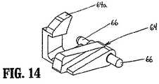
図5、図13および図14を参照すると、旋回部材66を備えるラックロック64は、旋回部材66の周りで、ハウジング半セクション38aと38bとの間に旋回可能に支持される。付勢部材67a(これは、好ましくは、ねじりばねである)が、ラックロック64を、図5に示されるような時計回り方向に推進するように、位置決めされる。ラックロック64は、ハウジング38の内部に位置するブロック部分64aを備える。このブロック部分64aは、DLU 16がステープリングデバイス10に取り付けられておらず、そして可動ハンドル28が圧縮される場合に、つめ48の係合フィンガー62と起動シャフト52の歯付きのラック60との間の係合を防止する(図18を参照のこと)。DLUがデバイス10に取り付けられると、ラックロック64は、以下に記載される様式で旋回して、ラックロック64のブロック部分64aを非ブロック位置まで移動させる。この非ブロック位置において、つめ48のフィンガー62は、起動シャフト52の歯付きのラック60と自由に係合する。ラックロック64はまた、起動シャフト52の凹部52aの内部に位置するロック部分64bを備え、このロック部分64bは、DLU16(図1)がこのデバイスに取り付けられる後まで、起動シャフト52の軸方向の移動を防止する。 Referring to FIGS. 5, 13 and 14, the
図5および図19を参照すると、垂直つめ69は、ハウジング半セクション38aと38bとの間に規定されたスロット68の内部に、スライド可能に位置決めされる。垂直つめ69は、延長された位置または上方位置から、引き込まれた位置または下方位置へと移動可能である。この延長された位置または上方位置において、つめ69の先端69aは、起動シャフト52の遠位端に形成された切り欠き67と係合し、そしてこの引き込まれた位置または下方位置において、つめ69の先端69aは、起動シャフト52から間隔を空ける。ハウジング半セクション38aと38bとの間に支持されたばね70は、つめ69を、延長された位置に推進するように位置決めされる。この延長された位置において、つめ69は、起動シャフト52の前進を防止し、ステープリングデバイス10の発射を防止する。 Referring to FIGS. 5 and 19, the
プランジャ72は、ハウジング半セクション38aおよび38bに形成された、間隔を空けた円筒形チャネル74の間に、往復可能に支持される。プランジャ72は、カム部材76を備える。ばね78が、円筒形チャネル74の内部で、プランジャ72の各端部に位置決めされる。ばね78は、垂直つめ69に形成されたカム表面80の対の間の中心にカム部材76が位置する位置に、プランジャ72を推進する。各カム表面80には、凹部82aが形成されており(図19)、この凹部82aは、プランジャ72のカム部材76を解放可能に受容するためのものである。
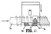
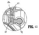
プランジャ72の各端部72a(図1)は、静止ハンドル26を通って延び、そしてばね78の1つの付勢に逆らって押され、カム部材76を、垂直つめ66のカム表面80のそれぞれ1つと強制的に係合させ得る。カム機構76がカム表面80の1つと係合するように移動すると、垂直つめ69は、延長された位置から引き込まれた位置へと推進され、垂直つめ69の先端69aを移動させて、起動シャフト52の切り欠き67から外す。図61および図62を参照のこと、ステープリングデバイス10は、このとき、発射の準備ができた位置にある。カム部材76の先端76aを、それぞれのカム表面80の凹部80aの内部に位置決めすることにより、垂直つめは、引き込まれた位置に保持され、デバイス10は、発射の準備ができた位置に維持される。 Each
(引き込み機構)
戻しノブ36(図1)を備える引き込み機構は、結合棒82によって、起動シャフト52の近位端に接続される。結合棒82は、右係合部分82aおよび左係合部分82bを有し、これらの右係合部分82aおよび左係合部分82bは、ハウジング半セクション38aおよび38bに形成された細長スロット83(図1)を通って延び、そして戻しノブ36を受容するような寸法にされる。結合棒82の中心部分82cは、起動シャフト52の近位端に形成されたスロット84の内部にスライド可能に受容されるような寸法にされる。解放プレート86は、2つのピン88によって、起動シャフト52の片側に支持される。ピン88は、解放プレート86を通して形成された、角度の付いたカムスロット90の内部に位置決めされる。結合棒82は、解放プレート86の近位端に形成された開口部92を通って延びる。(Retraction mechanism)
The retraction mechanism comprising the return knob 36 (FIG. 1) is connected to the proximal end of the
使用の際に、ノブ36が外科医によって後方に引かれると、結合棒82が起動シャフト52のスロット84の内部でスライドするにつれて、結合棒82は、最初、解放プレート86を、起動シャフト52に対して後方に移動させる。このことが起こると、ピン88は、解放プレート86にカム作用して、起動シャフト52の歯付きのラック60を覆う位置まで下向きに移動させ、つめ48のフィンガー62を、歯付きのラック60から脱係合させる。結合棒82が、スロット84の後端84aと係合する位置まで後方に引かれると、ノブ36の後方へのさらなる移動が、起動シャフト52および発射棒58の近位への移動を引き起こす。 In use, when the
フック96は、起動シャフト52の上表面に形成されたスロット98に支持される。フック96は、結合棒82を受容するような寸法にされた貫通ボア96aを備える。フック96の前端は、ばね100の一方のループ状端部100aを受容するように構成された、上向きに曲がった部分98を備える。ばね100の反対側の端部は、起動シャフト52に形成されたポスト102を受容するような寸法にされたループ100bを備える。ばね100は、結合棒82を起動シャフト52のスロット84の前端の方へと推進するために、緊張状態で維持される。結合棒82が起動シャフト52のスロット84の前端に位置する場合、解放プレート86は、起動シャフト52の歯付きのラック60の上方の上昇位置に保持されるか、またはカム作用により動かされる(図8)。 The
(回転アセンブリ)
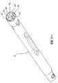
図5および図10〜図12を参照すると、回転ノブ32は、好ましくは、成型されたプラスチックの半セクション32aおよび32bから形成されるが、他の材料(例えば、金属)および他の製造方法が、予測される。回転可能なノブ32の近位端の内面は、環状リング106を備え、この環状リング106は、ハンドルアセンブリ12のバレル部分30の前端に形成された環状スロット108の内部に受容されて、ノブ32をハンドルアセンブリ12に回転可能に取り付けるような寸法にされる。Oリング107が、環状リング106とハンドルアセンブリ12との間に配置され、ノブ32とハンドルアセンブリ12との間の摩擦牽引を生じる。この摩擦牽引は、ハンドルアセンブリ12に対するノブ32の自由な回転を防止する。回転可能なノブ32の近位端の外面は、スカラップ状の構成物110を備え、回転可能なノブ32の把持を容易にする。回転可能なノブ32の遠位端の内面は、開口部112を規定し、そして細長本体14の近位端に形成された開口部116の内部に受容されるような構成および寸法にされた突出部114を備える。回転可能なノブ32の中心部分は、ポスト118を備え、そして以下に詳細に記載されるように、ステープリングデバイス10の関節運動機構を作動可能に受容するような構成にされた、横断チャネル120を規定する。(Rotating assembly)
5 and 10-12, the
(関節運動機構)
図15もまた参照すると、本開示のステープリングデバイス10の関節運動機構は、関節運動レバー122、カム部材124、カムカバー126、駆動部材128、および関節運動部材またはリンク130(図11)を備える。関節運動レバー122は、レバーピン132によって、回転可能なノブ32のポスト118に回転可能に固定される。レバーピン132は、レバー122とは別個の要素として示されるが、ピン132は、レバー122と一体的に形成され得ることが予測される。突出部134(図12)は、レバー122の下表面から下向きに延び、そしてカムカバー126に形成された細長スロット136の内部に受容される。カム部材124は、2つのプレスばめ突出部126a(図15)によって、カムカバー126の基部にしっかりと固定される。これらのプレスばめ突出部は、カム部材124に形成された開口部124aの内部に受容される。あるいは、他の公知の固定技術(ねじ、スナップばめコネクタ、溶接、インターロック部材など)が、カムカバー126をカム部材124に固定するために使用され得る。カムカバー126およびカム部材124は、前レッジおよび後レッジ140を有するアセンブリを規定し得る。このアセンブリは、横断チャネル120の内部にスライド可能に位置決めされるような寸法にされる。レッジ140は、チャネル120に形成される凹部142の内部に受容されて、カムカバーとカム部材とのアセンブリが、チャネル120から外れることを防止し、そしてカムカバーおよびカム部材が直線状に移動するように制限する。カムカバー126は、プラスチックから形成され得、そしてカム部材124は、金属(例えば、ステンレス鋼)から形成され得る。あるいは、他の構成材料が予測される。(Joint movement mechanism)
Referring also to FIG. 15, the articulation mechanism of the stapling
回転可能なノブ32の横断チャネル120は、このチャネルを通って延びる長手軸方向スロット144を備える。カム部材124は、このカム部材を通して形成された、段状のカムスロット146を有する。カムピン148は、第一の突出部150を備え、この第一の突出部150は、図12に見られるように、長手軸方向スロット144を通って上方に延び、そしてカム部材124の段状のカムスロット146の内部に受容される。カムピン148はまた、第二の突出部152を備え、この第二の突出部152は、図12に見られるように、駆動部材128に形成された開口部154の内部に下向きに延びる。 The
駆動部材128は、開口部154を備える本体部分128aと、長手軸方向の延長部128bとを備える。係合部材156は、長手軸方向延長部128bの遠位端に形成される。係合部材156は、関節運動リンク130の近位端に形成された開口部158の内部に受容されるように構成される。関節運動リンク130の遠位端はまた、以下に詳細に記載されるように、DLU 16(図1)の内部に位置決めされる関節運動リンクを係合するための、係合構造体160を備える。 The
作動において、関節運動レバー122がレバーピン132の周りに回転すると、突出部134は、カムカバー126とカム部材124とのアセンブリを、横断チャネル120を横切って移動させる。カム部材124の、横断チャネル124を横切る運動は、段状のカムスロット146を、カムピン148の第一の突出部150に対して移動させ、これによって、カムピン148を、長手軸方向スロット144を通して移動させる。カムピン148の長手軸方向の移動は、駆動部材128および関節運動リンク130の、対応する長手軸方向での移動を引き起こす。関節運動リンク130と関節運動構造体との、DLU 16の内部での相互接続は、以下で詳細に記載される。 In operation, as the
(DLUセンサ機構)
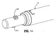
図5〜図12を参照して、外科手術用ステープリングデバイス10は、DLU 16が細長本体14に取り付けられたか否かを決定するためのセンサ機構を備える。このセンサ機構は、センサプレート170(図5)、ラックロック解放部材172、およびセンサキャップ174(図11)を備える。細長本体14が延長した長さである場合、センサ管(図示せず)は、センサプレート170とセンサキャップ174との間に位置し、センサプレート170の移動をセンサキャップ174に移し得る。センサプレート170は、発射棒58に形成された平坦部58aに沿ってスライド可能に位置し、そして遠位端170aおよび近位端170bを備える。代替の実施形態において、シムまたはスペーサー170c(図12A)が、細長本体14の内壁の間で、センサプレート170上に位置し得る。シム170cは、センサプレート170を発射棒58にスライド可能に接触させ、そしてセンサキャップ174と整列させて位置されるように機能し、これによって、センサプレート170が、センサキャップ174と重なること、およびセンサキャップ174との軸方向接触を失うことを防止する。センサプレート170とは別体の要素として示されるが、シム170cは、センサプレート170と一体的にか、またはモノリシックに形成され得る。センサキャップ174は、回転可能なノブ32の内部に、進められた位置と引き込まれた位置との間でスライド可能に配置され、そして関節運動ロックタブ174a、近位フランジ174b、および上平坦表面174cを備える(図11を参照のこと)。上平坦表面174cは、横断チャネル120の下方で、回転可能なノブ32の内部に位置し、その結果、タブ174aは、ノブ32の開口部を通って、カムカバー126に形成された切り出し部176およびカム部材124の内部へと上方に延びる。センサキャップ174が進められた位置にある場合、タブ174aは、切り出し部176の内部に位置し、横断チャネル120に沿ったカム部材124の移動を防止し、外科手術用デバイス10の関節運動を防止する。センサキャップ174が、以下に記載される様式で、引き込まれた位置に移動すると、タブ174aは、切り出し部176から近位に移動して、カム部材124の、横断チャネル120に沿った移動を可能にし、従って、外科手術用ステープリングデバイス10の関節運動を可能にする。(DLU sensor mechanism)
5-12, the
ラックロック解放部材172は、センサキャップ174の係合フランジ174bと係合するように構成された遠位端172aと、ラックロック64に隣接して位置する近位端172bを備える。付勢部材180(例えば、コイルばね)が、ラックロック解放部材172に形成されたスロット172cの内部で、スロット172cの一端と、ハウジングアセンブリ12からスロット172cの内部に延びるフィンガー(図示せず)との間に位置し、ロックラック解放部材172を遠位に推進し、これによって、センサキャップ174およびセンサプレート170を、進められた位置まで遠位に推進する。 The rack
作動において、DLUが外科手術用ステープリングデバイス10に取り付けられていない場合、付勢部材180は、ロックラック解放部材172、センサキャップ174およびセンサプレート170を、これらの進められた位置に維持する。上で議論されたように、進められた位置において、センサキャップロックタブ174aは、カム部材の切り取り部176の内部に位置し、外科手術用ステープリングデバイス10の関節運動を防止する。進められた位置において、ロックラック解放部材172はまた、ラックロック64から間隔を空け、その結果、ラックロック64のロック部分64bは、起動シャフト52に形成された凹部52aの内部に位置し、起動シャフト52を、固定された引き込まれた位置にロックし、そしてラックロック64のブロック部分64aは、つめ48と起動シャフト52の歯付きのラック60との係合を防止するように位置する。DLU 16が細長本体14の遠位端に固定されると、DLUの近位端は、センサプレート170の遠位端170aに固定され、センサプレート170を近位に移動させる。センサプレート170の近位への移動は、センサキャップ174およびロックラック解放部材172の対応する近位への移動を引き起こす。センサキャップ174の、引き込まれた位置への近位への移動は、ロックタブ174aをカム部材の切り出し部176から取り外し、ステープリングデバイス10の選択的な関節運動を可能にする。ロックラック解放部材172が近位に移動すると、部材172の近位端172bは、ラックロック64の底面に当接して、ラックロック64のロック部分64bを、起動シャフト52の凹部52aから上方に旋回させ、起動シャフト52が進むことを容易にし、そしてラックロック64のブロック部分64aを、つめ48の係合フィンガー62と起動シャフト52の歯付きのラック60との間の係合を妨害しない位置まで旋回させる。 In operation, when the DLU is not attached to the
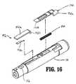
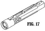
図11、図12、図16および図17を参照すると、細長本体14は、本体部分14a、本体カバー14b、および端部キャップ14cを備える。本体カバー14bは、本体部分14aの周りに位置し、そして端部キャップ14cは、本体部分14aの近位端に固定される。細長本体14は、上で議論されたように、回転可能な半セクション32aおよび32bに形成された突出部114を介して、これらの半セクション32aと32bとの間に固定される。この突出部114は、本体部分14aの近位端に形成された開口部116(開口部116aもまた、端部キャップ14cを通して形成される)の内部に位置する。細長本体14は、長手軸方向の貫通ボアを規定し、この貫通ボアを通って、発射棒58、センサプレート170、および関節運動リンク130が延びる。上で議論されたように、細長本体14が延長した長さである場合、センサ管もまた、細長本体14の内部に提供され得る。 Referring to FIGS. 11, 12, 16, and 17, the
ロックボタン190およびプレートとばねとのアセンブリ192は、細長本体14に形成された凹部内に支持される。ロックボタン190は、ばねアセンブリ192(図12を参照のこと)の遠位で、細長本体14の遠位端に隣接してスライド可能に位置し、そして遠位係合フィンガー190aおよび近位テーパ状当接表面190bを備える。フィンガー190aは、DLU 16(図1)を細長本体14に取り付ける間、DLU 16の近位端と係合するように位置決めされる。付勢部材194が、ロックボタン190を遠位方向に推進するために、提供される。プレートとばねとのアセンブリ192は、ブロック部分192bを有するプレート192aと、ばね部材192cとを備える。ばね部材192cは、プレート192aに直接固定される、板ばねであり得る。あるいは、他の構成が予測され、例えば、プレートおよびばね部材は、別体の要素である。ブロック部分192bは、発射棒58(図12)に形成された切り欠き196に隣接して位置する。
DLUが、細長本体14の遠位端に取り付けられる場合、以下でより詳細に記載されるように、このDLUは、細長本体14に挿入され、そして細長本体14に対して回転して、DLU 16をこの細長本体14にロックする。DLU 16を細長本体14に挿入する間、DLU 16の近位端は、ロックボタン190のフィンガー190aに係合し、そしてロックボタン190を、ばね194の付勢に逆らって近位に押し付け、その結果、ロックボタン190の当接表面190bは、アセンブリ192のプレート192aに係合する。当接表面190bとプレート192aとの間の係合は、ロック部分192bを、ばね部材192cの付勢に逆らって発射棒58の切り欠き196内に移動させ、発射棒58を、軸方向に固定された位置にロックし、DLUがロックされた位置に回転されるまで、このデバイスの発射を防止する。DLUがロック位置に回転されると、ばね194は、ロックボタン190を、プレート192aから間隔を空けた遠位位置まで戻し、そしてばね部材192cは、ロック部分192bを、発射棒58の切り欠き196から推進して、発射棒58の軸方向の移動を可能にする。好ましくは、ロックボタン190をその遠位位置に移動させることにより、DLUが係合本体14にロックされることの可聴指標が提供される。 When the DLU is attached to the distal end of the
図20は、DLUを外科手術用ステープリングデバイス10の細長本体14に取り付ける前の、外科手術用ステープリングデバイス10およびDLU 16を図示する。上で議論されたように、DLU 16をデバイス10に取り付ける前に、可動ハンドル16が、ラックロック64によって作動不可能にされ、これにより、つめ48が起動シャフト52の歯付きのラック60に係合することを防止し、そして起動シャフト52を固定された軸方向位置にロックする。 FIG. 20 illustrates the
図21もまた参照すると、使い捨て装填ユニット16は、近位本体部分18および遠位工具アセンブリ20を備え、この近位本体部分18は、細長本体部分14の遠位端と解放可能に係合するように構成されており、そしてこの遠位工具アセンブリ20は、設置アセンブリ202によって、本体部分18の遠位端に旋回可能に固定される(図28)。 Referring also to FIG. 21, the
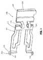
図22〜図28もまた参照すると、工具アセンブリ20は、アンビルアセンブリ24およびカートリッジアセンブリ22(図22)を備える。アンビルアセンブリ24は、アンビル部分204およびカバープレート208を備え、このアンビル部分204は、複数のステープル変形凹部206(図23)を有し、そしてこのカバープレート208は、アンビル部分204の上表面に固定されて、これらの間に空洞210を規定する(図25)。カバープレート208は、ステープリングデバイス10の接近および発射の間に、組織を挟むことを防止するために提供される。空洞210は、軸方向駆動アセンブリ212の遠位端をスライド可能に受容するような寸法にされる(図28を参照のこと)。長手軸方向スロット214は、アンビル部分204を通って延び、軸方向駆動アセンブリ212の保持フランジ284(図28)の、アンビル空洞210を通る通過を容易にする。アンビル部分204に形成されたカム作用表面209は、軸方向駆動アセンブリ212によって係合されるように位置決めされ、アンビルアセンブリとカートリッジアセンブリとの接近を容易にし、そして組織198のクランプを容易にする(図25)。アンビル部分204に形成された1対の旋回部材211が、キャリア216に形成されたスロット213の内部に位置決めされ、アンビル部分を、間隔を空けた位置と接近した位置との間で案内する。1対の安定化部材215が、キャリア216に形成されたそれぞれのショルダー217に係合して、カム作用表面209が旋回部材211の周りで旋回する場合に、アンビル部分204がステープルカートリッジ220に対して軸方向にスライドすることを防止する。 Referring also to FIGS. 22-28, the
カートリッジアセンブリ22は、細長支持チャネル218を規定するキャリア216を備える。細長支持チャネル218は、ステープルカートリッジ220を受容するような寸法および構成にされる。対応するタブ222およびスロット224が、それぞれ、ステープルカートリッジ220および細長支持チャネル218に形成され、ステープルカートリッジ220を、支持チャネル218内の固定された位置に保持するように機能する。ステープルカートリッジ220に形成された1対の支持支柱223は、キャリア216の側壁に載るように位置し、支持チャネル218内で、ステープルカートリッジ220をさらに安定化させる。 The
ステープルカートリッジ220は、複数のファスナー226およびプッシャー228を受容するための、保持スロット225を備える。間隔を空けた複数の長手軸方向スロット230は、ステープルカートリッジ220を通って延び、起動そり234の直立カムウェッジ232を収容する。中心長手軸方向スロット282は、ステープルカートリッジ220の長さに沿って延び、ナイフ刃280(図28)の通過を容易にする。外科手術用ステープラー10の作動の間、起動そり234は、ステープルカートリッジ220の長手軸方向スロット230を通って並進し、カムウェッジ232を進めてプッシャー228と連続的に接触させ、プッシャー228を、スロット224内で垂直に並進させ、そしてファスナー226を、スロット224からアンビルアセンブリ20のステープル変形空洞206内へと推進する。
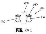
図28および図29を参照すると、設置アセンブリ202は、上設置部分236および下設置部分238を備える。各設置部分は、両側にねじ切りされたボア240を備え、これらのボア240は、これらの設置部分にキャリア216の近位端を固定するための、ねじ切りされたボルト242(図22を参照のこと)を受容するような寸法にされる。中心に位置する1対の旋回部材244は、1対の結合部材246を通って上設置部分236と下設置部分238との間に延び、これらの結合部材は、本体部分18の遠位端に係合する。結合部材246の各々は、インターロック近位部分248を備え、このインターロック近位部分248は、本体部分18の近位端に形成された溝249に受容されて、設置アセンブリ202および本体部分18を、このインターロック近位部分に対して長手軸方向に固定して保持する。 Referring to FIGS. 28 and 29, the installation assembly 202 includes an
使い捨て装填ユニット16の本体部分18は、上ハウジング半体250および下ハウジング半体252を備え、これらのハウジング半体は、外側ケーシング251に収容される。ハウジング半体250の近位端は、係合突起254を備え、これらの係合突起254は、細長本体部分14を、差込みカップリング型の様式で解放可能に係合するためのものである。ハウジング半体250の近位端はまた、挿入先端193を備え、この挿入先端193は、以下でさらに詳細に議論される。ハウジング半体250および252は、軸方向駆動アセンブリ212をスライド可能に受容するためのチャネル253を規定する。第二の関節運動リンク256は、ハウジング半体250と252との間に形成されたスロット258内にスライド可能に位置決めされるような寸法にされる。1対の押出しプレート255は、本体部分18の遠位端に隣接して、軸方向駆動アセンブリ212の遠位端に隣接して位置決めされ、工具アセンブリ20の関節運動および発射の間、駆動アセンブリ212が外側に膨らむことを防止する。 The
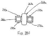
図28a〜図28hは、押出しプレートアセンブリ254aとして一般的に示される、押出しプレート255の代替の実施形態を図示する。押出しプレートアセンブリ254aは、可撓性本体255aおよびH字型ブロック256aを備える。可撓性本体255aは、近位端258aおよび遠位端260aを有する。これらの遠位端および近位端の各々は、それぞれ、保持部分258bおよび260bを備える。保持部分258bは、DLU 16の上ハウジング半体250および/または下ハウジング半体252に形成された凹部250aおよび/または252a内にしっかりと受容され、そして係合され、かつそのように構成される(図28b)。保持セクション260bは、1対のJ字型取り付け部材を備え、このJ字型取り付け部材は、設置アセンブリ202の上設置部分236および/または下設置部分238にそれぞれ形成された凹部236aおよび238aの内部にしっかりと受容され、そして係合し、かつそのように構成される。J字型取り付け部材の先端260cは、凹部236aおよび238b(図28g)に係合し、そしてロックされるように、角度を付けられており、そして好ましくは、凹部を形成する壁にプレスばめされる。ロック部材268a(図28d〜図28f)は、1対のレッグ266aおよび中心ウェブ267aを有するH字型本体を備える。各レッグ266aは、テーパ状の端部を有する細長保持部分270aを備える。ロック部材268aは、保持セクション258bに隣接してDLU 16の上ハウジング半体250および下ハウジング半体252にそれぞれ形成された凹部250aおよび252a内にプレスばめされ、保持セクション258bを、これらの凹部の内部にしっかりと固定する。押出しプレートアセンブリ254aの中心部分は、1対の実質的にU字型のばね部分262aを備える。U字型ばね部分262aは、工具アセンブリ20が起動される場合(すなわち、接近されるかまたは発射される場合)に、本体255aの中心部分が外向きにわずかに撓み、駆動アセンブリ212(図28)のスライドおよび関節運動の動きに適用することを可能にする。図28hに示されるように、H字型ブロック256aは、ばね部分262aの周りに小さいギャップを有するように位置決めされ、U字型ばね部分262aが撓み得る程度を制限し、デバイス10の起動の間に押出しプレートアセンブリ254aと駆動アセンブリ212とが締まることを防止する。押出しプレートアセンブリ254aは、駆動アセンブリ212の各側に位置し、デバイス10の起動の間(デバイス10が関節運動する場合を含む)に、駆動アセンブリ212が外向きに膨らむことを防止する。 28a-28h illustrate an alternative embodiment of an
図30および図31を参照すると、第二の関節運動リンク256は、少なくとも1つの細長金属プレートを備える。1つの実施形態において、2つ以上の金属プレートが積み重ねられて、リンク256を形成する。関節運動リンク256の近位端は、関節運動リンク130(図6を参照のこと)を係合するように構成されたフック部分258を備え、そして遠位端は、設置アセンブリ202の設置部分238に形成された突出部262を係合するような寸法にされたループ260を備える。突出部262は、旋回ピン244から横方向にずれており、その結果、第二の関節運動リンク256の線形運動は、設置アセンブリ202を、旋回ピン244の周りで旋回させ、工具アセンブリ20を、本体部分18に対して関節運動させる。 Referring to FIGS. 30 and 31, the
図32〜図35、および図39を参照すると、軸方向駆動アセンブリ212は、細長駆動梁266を備え、この細長駆動梁266は、遠位作業ヘッド268および近位係合セクション270を備える。駆動梁266は、材料の単一のシートから構成され得るか、または好ましくは、複数の積み重ねられたシートから形成され得る。係合セクション270は、1対の係合フィンガー270aおよび270bを備え、これらの係合フィンガー270aおよび270bは、駆動部材272に形成された対応する1対の保持スロット272aおよび272bに設置可能に係合するような寸法および構成にされる。駆動部材272は、近位窓274を備え、この近位窓274は、使い捨て装填ユニット16の近位端が外科手術用ステープリング装置10の細長本体14と係合する場合に、発射棒58の遠位端276(図12を参照のこと)を受容するように構成される。 With reference to FIGS. 32-35 and 39, the
駆動梁266の作業ヘッド268の遠位端は、ナイフ刃280を支持する垂直支持支柱278(図32)と、当接表面283とによって規定される。この当接表面283は、ステープリング手順の間、起動そり234の中心部分に係合する。表面285は、表面283の基部に位置し、そして支持部材287(図39)を受容するように構成される。この支持部材287は、ステープルカートリッジ220の底部に沿ってスライド可能に位置決めされる。ナイフ刃280は、ステープルカートリッジ220(図22)の中心長手軸方向スロット282を通って、駆動そり234のわずかに後方に並進し、ステープル止めされた身体組織の列の間に切開を形成するように位置決めされる。保持フランジ284は、垂直支柱278から遠位に突出し、そしてその遠位端において、円筒形カムローラ286を支持する。カムローラ286は、アンビル本体204のカム表面209に係合して、アンビル部分204を身体組織にクランプさせるような寸法および構成にされる。 The distal end of the working
図21および図36〜図38もまた参照すると、ロックデバイス288は、旋回ピン290の周りで、駆動部材270に旋回可能に固定される。ロックデバイス288は、チャネル296を規定する1対の細長滑走面292および294を備える。ウェブ298が、滑走面292および294の上面の一部を接合し、そして駆動部材272から遠位の位置で、駆動梁266に形成された細長スロット298の内部にフィットするような構成および寸法にされる。垂直カム300および302が、それぞれ、滑走面292および294から伸び、そして下ハウジング半体252の内面に沿って適合する。図38に最もよく示されるように、ねじりばね304が、駆動部材270に隣接して位置決めされ、そしてロックデバイス288の水平カム300および302(図36)に係合し、ロックデバイス288を、下ハウジング半体252に向けて下方に、レッジ310上へと垂直に付勢する。ロックデバイス288は、軸方向駆動アセンブリ212と一緒に、ハウジング部分200を通って並進する。ロックデバイス288の作動が、以下で記載される。 Referring also to FIGS. 21 and 36-38, the
図80〜図96は、本開示の使い捨て装填ユニットの代替の実施形態を図示する。DLU 16に関して上で議論されたように、DLU 516は、設置アセンブリ522を備える。設置アセンブリ522は、上設置部分580および下設置部分582を備える。中心に位置する旋回部材584は、上設置部分580および下設置部分582の各々から、結合部材586に形成されたか移行部586aを通って延び、この結合部材586は、近位本体部分518の遠位端と係合する。結合部材586の各々は、インターロック近位部分588を備え、このインターロック近位部分588は、本体部分518の近位端に形成された溝590に受容されて、設置アセンブリ522および本体部分518を、互いに対して長手軸方向に固定された位置に保持する。 80-96 illustrate an alternative embodiment of the disposable loading unit of the present disclosure. As discussed above with respect to DLU 16,
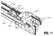
使い捨て装填ユニット516(図21)の本体部分518は、上ハウジング半体592および下ハウジング半体594を備え、これらのハウジング半体は、外側ケーシング596に収容される。ハウジング半体592の近位端は、器具10(図20)の遠位端を解放可能に係合するための係合ラグ596と、挿入先端598とを備える。ラグ596は、器具10の遠位端と差込みカップリング型の結合を形成する。ハウジング半体592および594は、軸方向駆動アセンブリ536をスライド可能に受容するためのチャネル600を規定する。関節運動リンク602は、上ハウジング半体592および下ハウジング半体594に形成されたスロット604の内部にスライド可能に位置決めされるような寸法にされる。1対の押出しプレートアセンブリ606が、本体部分518の遠位端に隣接して、軸方向駆動アセンブリ536の遠位端に隣接して位置決めされ、工具アセンブリ520の関節運動および発射の間に、駆動アセンブリ536が締まったり外向きに膨らんだりすることを防止する。 The
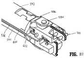
図81〜図89は、押出しプレートアセンブリ606の細部を図示する。各押出しプレートアセンブリ606は、横方向に可撓性の本体610およびH字型ブロック612を備える。可撓性本体610は、近位端614および遠位端616を備える。これらの遠位端および近位端の各々は、それぞれ、保持部分618および620を備える。保持部分618は、DLU 16(図21、図82、図85)の上ハウジング半体592および/または下ハウジング半体594に形成された凹部621および/または622の内部にしっかりと受容され、そして係合し、かつこのように構成される。保持セクション620は、1対のJ字型取り付け部材を備え、これらのJ字型取り付け部材は、ハウジングアセンブリ522の上設置部分580および/または下設置部分582に形成された凹部623および624にしっかりと受容され、そして係合し、そしてそのように構成される。J字型取り付け部材の先端630は、凹部623および624(図82)に係合されてロックされるように、角度を付けられており、そして好ましくは、これらの凹部を形成する壁にプレスばめされる。 81-89 illustrate details of the
ロック部材634(図84a〜図84c)は、1対のレッグ636および中心ウェブ638を有するH字型本体を備える。各レッグ636は、テーパ状の端部を有する細長保持突出部640を備える。ロック部材634は、保持セクション618に隣接して、DLU 16(図21)の上ハウジング半体592および下ハウジング半体594(図83)に形成された凹部621および622にプレスばめされ、かつそのような寸法にされ、保持セクション618をこれらの凹部の内部にしっかりと固定する。押出しプレートアセンブリ606の中心部分は、ばね部分すなわちばねセクションを備え、これは、好ましくは、実質的にU字型の1対のばね部分644を備える。U字型ばね部分644は、本体610の中心部分が軸方向に伸長し、そして長手方向軸に対してわずかに外向きに、または長手方向軸のわずかに外向きに曲がることを可能にし、駆動アセンブリ536(図80)のスライドおよび関節運動の動き(工具アセンブリ20(図21)が起動(すなわち、接近または発射)される場合を含む)に適合する。軸方向に伸長し得る支持部材を提供することによって、旋回軸に隣接する駆動アセンブリの内面と外面とに沿った曲率半径の差に起因するこの駆動アセンブリの束縛が、かなり減少される。 The locking member 634 (FIGS. 84a-84c) comprises an H-shaped body having a pair of
図81に示されるように、制限部材(これは、好ましくは、H字型ブロック612として形成される)は、ばね部分644の周りに小さいギャップを有するように位置決めされ、U字型ばね部分644が撓み得る程度を制限し、デバイス510の起動の間の押出しプレートアセンブリ606と駆動アセンブリ536とが結合するかまたは締まることを防止する。押出しプレートアセンブリ606は、駆動アセンブリ536の各側に、工具アセンブリ512の旋回軸に隣接して位置し、デバイス510の起動の間(デバイス510が関節運動する場合を含む)に、駆動アセンブリ536が外向きに曲がり、そして/または結合することを防止する。 As shown in FIG. 81, the limiting member (which is preferably formed as an H-shaped block 612) is positioned to have a small gap around the
図80および図87〜93を参照すると、関節運動リンク602は、少なくとも1つの細長金属プレートを備える。2つ以上の金属プレートが積み重ねられて、リンク602を形成し得る。関節運動リンク602の近位端は、フック部分660を備え、このフック部分660は、器具510の内部に位置決めされた関節運動機構と係合するように構成され、そしてその遠位端は、ループ662を備える。このループ662は、設置アセンブリ522の設置部分580に形成された突出部664に係合するような寸法にされる。突出部664は、旋回部材584から横方向にずれており、その結果、関節運動リンク602の直線状の動きは、設置アセンブリ522を、旋回部材584の周りで旋回させ、工具アセンブリ20(図21)を、近位本体部分518に対して関節運動させる。 Referring to FIGS. 80 and 87-93, articulation link 602 comprises at least one elongated metal plate. Two or more metal plates can be stacked to form the
細長本体部分14(図1)または近位本体部分518は、保持部材を備え得、この保持部材は、関節運動リンク602に所定の力が適用されるまで、工具アセンブリ520の関節運動を防止するためのものである。1つの実施形態において、近位本体部分518の下ハウジング半体594は、凹部666を備え、この凹部666は、付勢部材668(例えば、圧縮ばね)およびボール670を受容するような寸法にされる。関節運動部材またはリンク602は、ボール670を部分的に受容するような寸法にされた、窪み672を備える、ボール670と窪み672との間の係合は、工具アセンブリを関節運動させることが望まれるまで、関節運動リンク602を非関節運動位置に保持する。図90〜図93を参照すると、代替の実施形態において、球状突出部674が、下ハウジング半体594とモノリシックに、または一体的に形成され、この突出部674は、関節運動リンク602の凹部(ここでは、窪み672として示される)の内部に受容されるような寸法である。切り出し部676が、下ハウジング半体594に形成され、その結果、突出部674は、可撓性の壁678に支持される。工具アセンブリ520が非関節運動位置にある場合、突出部674は、窪み672の内部に載り、所定の軸方向の力がリンク602に適用されない限り、関節運動リンク602(図91)の動きを防止する。充分な、または所定の軸方向の力がリンク602に適用され、そしてリンク602が動いて工具アセンブリを関節運動させると、可撓性の壁678は、図21に図示されるように下方に撓み、関節運動リンク602が遠位に動くことを可能にする。複数の突出部がこのハウジングに提供されて、この工具アセンブリが、複数の関節運動位置および非関節運動位置で選択的に保持され得ることが、予測される。あるいは、凹部がこのハウジングに形成され得、そして突出部が関節運動リンクに提供され得る。上に開示された保持部材は、このデバイスの細長本体部分14に形成され得ることもまた、予測される。 The elongate body portion 14 (FIG. 1) or the
図80および図94〜図96を参照すると、軸方向駆動アセンブリ536は、細長駆動梁680を備え、この細長駆動梁680は、遠位作業ヘッド682(図80)および近位係合セクション684を備える。駆動梁680は、材料の単一のシートから構成され得るか、または好ましくは、複数の積み重ねられたシートから構成され得る。係合セクション684は、1対の係合フィンガー686を備え、これらの係合フィンガー686は、駆動部材690に形成された対応する1対の保持スロット688を設置して係合するような寸法および構成にされる。駆動部材690は、近位窓692を備え、この近位窓692は、使い捨て装填ユニット512の近位端が外科手術用ステープリング器具10(図21)の細長本体と係合している場合に、器具10の発射棒の遠位端を受容するように構成される。 Referring to FIGS. 80 and 94-96, the
駆動梁680の遠位端は、垂直支持支柱694および当接表面696によって規定され、この垂直支持支柱694は、ナイフ刃578を支持し、そしてこの当接表面696は、ステープリング手順の間、起動そり234(図22)の中心部分と係合する。表面698は、表面696の基部に位置し、そして支持部材(図示せず)を受容するように構成される。この支持部材は、ステープルカートリッジアセンブリ22(図22)の底部に沿って、スライド可能に位置決めされる。ナイフ刃578は、起動そり234のわずかに後方の位置で、ステープルカートリッジアセンブリ22の中心長手軸方向スロットを通って並進し、ステープル留めされた身体組織の列の間に切開を形成するように位置決めされる。保持フランジ540は、垂直支柱694から遠位に突出し、そして円筒形カムローラ700を、その遠位端で支持する。カムローラ700は、アンビル本体204のカム表面209に係合して、アンビル本体204に身体組織をクランプさせるような寸法および構成にされる。 The distal end of the
図80および図93〜図96を参照すると、ロック部材702は、駆動梁680の近位端に支持される。ロック部材702は、ほぼH字型形状の構成ならびに1対のアーム710を有し、この構成は、第一のレッグ704および第二のレッグ706、横棒部分708、ならびに1対のアーム710を備える。各レッグ704および706は、横方向突出部712を備える。横棒部分708は、駆動アセンブリ536の駆動梁680に形成されたスロット714の内部に位置決めされる。突出部712は、下ハウジング半体594に形成された凹部716の内部に受容される。所定の力を可動ハンドル28に適用されて駆動梁680を遠位に進めることによって、駆動アセンブリが起動されると、突出部712は、凹部716から強制的に出され、器具510が起動されたという可聴指標または触覚指標を提供する。ロック部材702はまた、所定の軸方向の力が駆動梁680に適用されるまで、駆動梁680をDLU 512における固定された位置にロックすることによって、例えば、搬送の間のDLU 512の不注意による部分的な起動を防止する。 Referring to FIGS. 80 and 93-96, the locking
(作動の順序)
(A.DLUの取り付け)
図20および図40〜図48を参照すると、ステープリングデバイス10を使用するためには、DLU 16が、最初に、細長本体14の遠位端に固定される。DLU 16(図41)を細長本体14(図40)に固定するためには、DLU 16の挿入先端193が、発射棒58の遠位端276の周りに位置決めされ、そして図42および図43において矢印「A」によって示される方向に、軸方向に移動される。細長本体14の遠位端に形成されたチャネル(図示せず)は、第二の関節運動リンク256のフック部分258をスライド可能に受容するために、提供される。ラグ254はまた、細長本体14の遠位端のチャネル14b(図40)の内部に位置決めされる。挿入先端193が細長本体14の内部に進められるにつれて、ラグ254のうちの1つが、ロックボタン190の係合フィンガー190aに係合し、ロックボタン190を、ばね194の付勢に逆らって、図43および図44において矢印「B」によって示される方向に、細長本体14の内部で近位に移動させる。ロックボタン190が近位に移動すると、当接表面190bが、プレートとばねとのアセンブリ192のプレート192aに係合し、プレート192のブロック部分192bを、図44において矢印「C」によって示される方向に推進し、発射棒58(図44)に形成された切り欠き196に入れる。ブロック部分192bを発射棒58の切り欠き196の内部に位置決めすることによって、DLU 16がロック位置まで回転されるまで、ステープリングデバイス10が起動(すなわち、接近または発射)されることを防止する。(Operating order)
(A. Installation of DLU)
With reference to FIGS. 20 and 40-48, to use the
図45を参照すると、DLU 16を細長本体14において適所にロックするために、DLU 16および/または本体14は、図45において矢印「D」によって示される方向に互いに対して回転され、ナブ254を、ロックボタン190のフィンガー190aとの整列からはずすように動かす。このことが起こると、ロックボタン190は、ばね194によって、図48において矢印「E」によって示される方向に移動し、プレート192aのブロック部分192bが、ばね192cによって、図48において矢印「F」によって示される方向に動かされ、発射棒58の切り欠き196から出ることを可能にする。フィンガー190aは、ナブ254の側部の位置まで移動して、DLU 16を細長本体14にロックする。DLU 16が適所にロックされた後に、DLU 16を細長本体から取り外すためには、ロックボタン190が手で近位に動かされなければならず、そしてこのことは、発射棒58が引き込まれた位置にある場合にのみなされ得る。図46に図示されるように、DLU 16が細長本体14にロックされる場合、関節運動リンク130の係合構造体160は、第二の関節運動リンク256のフック部分258と作動可能に係合する。 Referring to FIG. 45, in order to lock
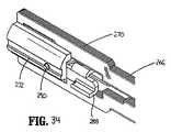
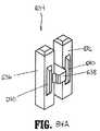
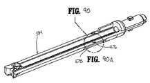
図40A〜図40Dは、デバイス10の細長本体の代替の実施形態(一般に、14’として示される)を図示する。細長本体14’は、遠位端15’を備え、この遠位端15’は、開口部14a’およびほぼ長手軸方向に延びるチャネル14b’を規定する。開口部14a’は、SULU 16の挿入先端193(図38)を受容するような寸法にされ、そしてチャネル14b’は、SULU 16のラグ254(図38)を受容するような寸法にされる。細長本体14’は、チャネル14b’を規定する壁14c’が、面取りされたかまたは角度の付いた遠位端14d’を有する点で、本体14(図40)とは異なる。面取りされた遠位端14d’は、チャネル14b’内に、漏斗様の挿入開口部14e’を提供する。 40A-40D illustrate an alternative embodiment of the elongate body of device 10 (generally shown as 14 '). The elongate body 14 'includes a distal end 15' that defines an
図40B〜図40Cを参照すると、SULU 16が本体部分14’の開口部14a’に挿入されると、ラグ254がチャネル14b’(図40C)と整列していない場合、面取りされた遠位端14d’が、ラグ254(および従って、SULU 16)にカム作用するかまたはラグ254を再度方向付け、その適切な、または整列された配向にする(図40D)。面取りされた遠位端14d’は、鋭利な侵入角を有するように図示されるが、他の角度が予測される。すなわち、面取りされた遠位端は、チャネル14b’へのより大きい入口開口部14e’(図40D)を規定する角度(例えば、60°以上)を有し得る。遠位端14d’についての他の構成が、予測される。例えば、遠位端14d’は、SULUを回転方向で案内するための、螺旋状表面を備え得る。 40B-40C, when
(B.センサ機構の作動)
ここで図44および図49〜図52を参照すると、DLU 16が、図44において矢印「A」によって示される方向に細長本体14に挿入される場合、DLU 16の先端193は、センサプレート170の遠位端170aに係合し、センサプレート170を、図44において矢印「G」によって示される方向に近位に移動させる。センサプレート170の近位端170bは、次に、センサキャップ174を、図49において矢印「H」によって示される方向に近位に強制的に動かす。センサキャップ174のフランジ174bは、ラックロック開放部材172と係合し、その結果、ラックロック解放部材172は、図51において「H」によって示される方向に近位に動かされ、ラックロック64と係合する。ラックロック解放部材172トラックロック64との係合により、ラックロック64は、図51において矢印「J」によって示される方向に回転し、ラックロック64のブロック部分64aを、つめ48と起動シャフト52の歯付きのラック60との間の係合をもはや妨害しない位置に動かし、そしてラックロック64のロック部分64bを動かして、起動シャフト52の凹部52aから外す。センサキャップ174の近位への移動はまた、センサキャップ174aを、図52において矢印「K」によって示される方向に、カム部材の切り出し部176から動かし、外科手術用ステープリングデバイス10の関節運動機構の作動を可能にする。(B. Operation of sensor mechanism)
44 and FIGS. 49-52, when the
図42Aおよび図52Aを参照すると、上で議論されたように、ステープリングデバイス10は、関節運動するDLUと関節運動しないDLUとの両方と共に使用可能である。関節運動しないDLU 16a(図42A)は、挿入先端193(図42を参照のこと)を備えない。従って、センサプレート170、センサキャップ174およびロック解放機構172を備えるセンサ機構は、DLU 16aが細長本体14に取り付けられる場合、より少ない距離だけ近位に移動する。このセンサ機構が近位に移動する距離は、ラックロック解放部材172を起動シャフト52から脱係合させるために十分であるが、タブ174aを切り出し部176(図52A)から移動させるためには不十分である。 42A and 52A, as discussed above, the stapling
図47〜図49を参照すると、DLUが外科手術用ステープリングデバイス10に固定される場合、垂直つめ66は、関節運動シャフト52に形成された当接表面52aの下方に位置し、そして引き込まれた位置に推進される。図50に図示されるように、この位置において、垂直つめ66のカム表面80は、プランジャ72のカム部材76の下方に位置する。外科手術用ステープリングデバイス10は、ここで、組織320の周りで接近される準備ができている(図45)。 47-49, when the DLU is secured to the
(C.接近)
図54および図55を参照すると、カートリッジアセンブリ22およびアンビルアセンブリ24を接近させるためには、可動ハンドル28が、図54において矢印「L」によって示される方向に、起動行程を介して動かされる。すなわち、可動ハンドル28は、ねじりばね42の付勢に逆らって、静止ハンドル26の方へと圧縮され、つめ48の係合フィンガー62を、起動シャフト52に形成されたショルダー52bと係合させる。起動行程を介する可動ハンドル28の引き続く移動は、起動シャフト52および発射棒58を前進させる。起動シャフト52が進むにつれて、起動シャフト52に形成された切り欠き67が、垂直つめ69と整列するように移動し、そして垂直つめ69は、ばね部材70によって、図55において矢印「M」によって示される方向に推進され、切り欠き67に入り、起動シャフト52のさらなる前進を防止する(図55)。(C. approach)
54 and 55, to approximate the
図56および図57を参照すると、発射棒58は、その遠位端において、駆動梁266を備える軸方向駆動アセンブリ212に接続され、その結果、発射棒58の前進は、図56および図57において矢印「N」によって示される方向に、駆動梁266を前進させる。駆動梁266が進むにつれて、カムローラ286は、アンビル部分204(図22)のカム表面209に係合するように移動し、アンビル部分204を、図57において矢印「O」によって示される方向に推進して、カートリッジアセンブリ22およびアンビルアセンブリ24を接近させ、これらのアセンブリの間に組織320をクランプさせる。 56 and 57, the firing
図58および図59を参照すると、可動ハンドル28が起動されてカートリッジアセンブリ22とアンビルアセンブリ24とを接近させた後に、付勢部材42が、ハンドル28を、図58において矢印「P」によって示される方向に戻し、静止ハンドル26から間隔を空けた、非圧縮位置にする。図示されるように、この位置において、垂直つめ69は、先端69aが起動シャフト52の切り欠き67の内部に位置する位置まで延長し、従って、起動シャフト52がさらに進むことを防止する。この延長した位置において、垂直つめ69のカム表面80は、プランジャ72のカム部材76と整列する(図59を参照のこと)。 Referring to FIGS. 58 and 59, after the
(D.プランジャの作動)
図60〜図62を参照すると、ステープリングデバイス10が接近する場合、垂直つめ69は、機動シャフト52の切り欠き67と係合して、起動シャフト52をこの接近した位置にロックする。起動シャフト52を解放するか、またはロック解除し、そしてステープルデバイス10を、発射の準備ができた位置にするために、プランジャ72が提供される。プランジャ72が、図61において矢印「Q」によって示される方向に押されると、プランジャ72のカム部材76が、垂直つめ69のカム表面80と係合し、垂直つめ69を、図61において矢印「R」によって示される方向に推進し、その引き込まれた位置にする。この引き込まれた位置において、垂直つめ69の先端69aは、起動シャフト52の切り欠き67の外側にあり、そしてデバイス10は、発射の準備ができた位置にある。垂直つめ69は、プランジャ72のカム表面76と、垂直つめ69のカム表面80の凹部82との間の係合によって、引き込まれた位置に維持される。(D. Actuation of plunger)
60-62, when the stapling
(E.外科手術用ステープリングデバイスの発射)
図63〜図65を参照すると、ステープリングデバイス10を発射するためには、可動ハンドル28が、図63において矢印「L」によって示される方向に、第二の起動行程を介して移動される。この間に、つめ48の係合フィンター62は、起動シャフト52の歯付きのラック60と係合し、起動シャフト52および発射棒58を遠位に進める。図60を再度参照すると、起動シャフト52が遠位に動くにつれて、起動シャフトに形成された第二の当接表面52bが、垂直つめ69と係合し、垂直つめ69を下向きに、図64において矢印「R」によって示される方向に移動させ、プランジャ72のカム部材76を、垂直つめ69のカム表面80から脱係合させ、そしてばね78が、図64において矢印「S」によって示される方向にプランジャ72を戻し、そのニュートラル位置にすることを可能にする。(E. Launch of surgical stapling device)
Referring to FIGS. 63-65, to fire the stapling
図66および図67を参照すると、発射棒58が上で議論されたよう式で進められると、駆動梁266が、図66および図67において矢印「T」によって示される方向に進められて、起動そり234をステープルカートリッジ22に通して進め、同時に、ナイフ280(図31)で組織を切断し、そしてプッシャー228を駆動させて、ステープル226をカートリッジから連続的に排出する。 66 and 67, when the firing
外科手術用ステープリングデバイス10は、ステープルカートリッジを有するDLUを受容するように適合される。このステープルカートリッジは、約30mm〜約60mmの長さを有する、直線状の列の状態のステープルを有する。外科手術用ステープリングデバイス10の発射の間の、可動ハンドル28の各起動行程により、起動シャフト52が約15mm前進するが、他の長さが予測される。従って、45mmのステープルの列を有するカートリッジを発射させるためには、可動ハンドル28は、可動ハンドル28の接近行程またはクランプ行程の後に、3回の起動行程を通って移動しなければならない。
(F.引き込み機構)
図68は、外科手術用ステープリングデバイス10の引き込み機構の作動を図示する。(F. Retraction mechanism)
FIG. 68 illustrates the operation of the retraction mechanism of the
使用において、戻しノブ36が、外科医によって、図68において矢印「U」によって示される方向に後方に引かれる場合、結合棒82は、棒82が起動シャフト52のスロット84内をスライドするにつれて、最初、解放プレート86を起動シャフト52に対して後方に移動させ、その結果、ピン88が、解放プレート86に、矢印「V」によって示される方向に下向きにカム作用して、起動シャフト52の歯付きのラック60を覆う位置にし、そしてつめ48のフィンガー62を、歯付きのラック60から脱係合させる。結合棒82が、スロット84の後端84a(図5A)と係合する位置まで後方に引かれると、ノブ36のさらなる後方への移動は、起動シャフト52および発射棒58の近位への移動を引き起こす。 In use, when the
(G.関節運動機構の作動)
図69〜図72を参照すると、関節運動レバー122は、工具アセンブリ20の関節運動を引き起こすように旋回可能である。より具体的には、関節運動レバー122は、レバーピン132(図12)の周りで回転または旋回し、レバー122の突出部134(図11)は、カムカバー126およびカム部材124を、回転可能なノブ32の横断チャネル120を横切って移動させる。横断チャネル124を横切るカム部材124の移動は、段付きのカムスロット146を、カムピン148の第一の突出部150に対して移動させ、これによって、カムピン148を、回転可能なノブ32(図11)の長手軸方向スロット144に通して移動させる。カムピン148の長手軸方向での移動は、駆動部材128および関節運動リンク130の、対応する長手軸方向の移動を引き起こす。図69に図示されるように、レバー122が反時計回りの方向に観点する場合、関節運動リンク130は、近位に移動するかまたは引き込まれる。図70に図示されるように、レバー122が時計回りの方向に回転する場合、関節運動リンク130は、遠位に移動するかまたは進められる。(G. Operation of articulation mechanism)
With reference to FIGS. 69-72, the
図71〜図73に図示されるように、関節運動リンク130の遠位端は、第二の関節運動リンク256の近位端に作動可能に接続される。関節運動リンク256の遠位端は、設置アセンブリ200(図73)の突出部262に接続される。突出部262は、旋回部材244から横方向にずれており、その結果、関節運動リンク256の移動は、工具アセンブリ20の関節運動を引き起こす。より具体的には、関節運動リンク130が引き込まれる場合(図69)、関節運動リンク256は引き込まれ、そして工具アセンブリ20は、図75において矢印「X」によって示される方向に関節運動する。関節運動リンク130が進められると(図70)、関節運動リンク256もまた進められ、そして工具アセンブリ20は、図74において矢印「Y」によって示される方向に関節運動する。 As shown in FIGS. 71-73, the distal end of
図76および図77を参照すると、回転ノブ32は、ハンドルアセンブリ12に対して回転可能であり、細長本体14およびDLU 16(工具アセンブリ20を含む)を、細長本体14の中心長手方向軸の周りで回転させる。図76および図77に図示されるように、外科手術用ステープリングデバイス10は、工具アセンブリ20が関節運動している間に回転され得る。デバイス10はまた、回転され得、その後、関節運動され得る。 Referring to FIGS. 76 and 77, the
(H.ロックアウト機構の作動)
ここで図36〜図38、図78および図79を参照して、ロックアウト作動の順序が、詳細に記載される。図38において、ロックアウトデバイス288は、発射前の位置で示されており、この発射前の位置において、垂直カム300および302が、下ハウジング半体252(図37)に形成された突出部330(図36)の頂部に載っている。この位置において、ロックデバイス288は、下ハウジング半体252の底面に形成された突出部332(図37)との整列から外れて保持されており、そしてウェブ298は、駆動梁266に規定された棚334(図38)と長手軸方向に併置される。この構成は、外科医が位置に満足するまで、ロックデバイス288を起動させて使い捨て装填ユニット16を使用不可能にすることなく、アンビル24(図39)が開かれ、そしてステープルされるべき組織上に再配置されることを可能にする。(H. Operation of lockout mechanism)
36-38, 78 and 79, the sequence of lockout operations will now be described in detail. In FIG. 38, the
図72に示されるように、駆動梁266の遠位への移動の際に、ロックデバイス288は、突出部330(図示せず)から外れ、そしてばね304によって、基部の下ハウジング半体252と係合するように、突出部332に対して遠位に付勢される。ロックデバイス288は、この装置の発射の間中、この構成に維持される。 As shown in FIG. 72, upon distal movement of the
駆動梁266を、図78において矢印「U」によって示される方向に引き込む際に、ロックデバイス288の最遠部が突出部332に接近するまで、ロックデバイス288は、突出部330を越えて通過し、そして突出部332の上に載る。ばね304は、ロックデバイス288を、突出部332と併置して整列するように付勢し、使い捨て装填ユニットを効果的に使用不可能にする。この装置を再度起動させようと試みる場合、発射棒58が、ロックデバイス288の近位端表面(この表面は、旋回ピン342の周りにモーメントを付与するように、対角線上にスロットが付いている)に当接する。その結果、ロックデバイス288の遠位端は、突出部332と接触するように、回転により推進される。図79において矢印「AA」によって示される方向に、遠位への力を加え続けることは、ロックデバイスに付与されるモーメントを増加させるようにしか働かず、従って、このロックデバイスは、突出部332に当接し、そして発射棒58の遠位への移動を妨げる。 When the
種々の改変が、本明細書中に開示された実施形態に対してなされ得ることが、理解される。従って、上記説明は、限定として解釈されるべきではなく、単に、好ましい実施形態の例示として解釈されるべきである。当業者は、添付の特許請求の範囲の範囲および精神の範囲内での、他の改変を予測する。 It will be understood that various modifications may be made to the embodiments disclosed herein. Therefore, the above description should not be construed as limiting, but merely as exemplifications of preferred embodiments. Those skilled in the art will envision other modifications within the scope and spirit of the claims appended hereto.
10 外科手術用ステープリングデバイス
12 ハンドルアセンブリ
14 細長本体
16 使い捨て装填ユニット
18 近位本体部分
20 遠位工具アセンブリ
22 カートリッジアセンブリ
24 アンビルアセンブリ10
Claims (10)
Translated fromJapanese近位端および遠位端を有する本体部分であって、該本体部分は、長手軸方向のボアを規定し、該本体部分の遠位端は、少なくとも1つのチャネルを規定する内壁を備える、本体部分;ならびに
近位本体部分および遠位工具アセンブリを有する使い捨て装填ユニットであって、該近位本体部分は、該本体部分の遠位端の内部に受容されるような寸法の挿入先端を備え、該挿入先端は、該挿入先端に形成された少なくとも1つの突起を有し、該少なくとも1つの突起の各々は、該少なくとも1つのチャネルのうちの1つの内部にスライド可能に受容されるような寸法である、使い捨て装填ユニット、
を備え、
該少なくとも1つのチャネルを規定する該内壁の遠位端は、該突起の1つ以上を該少なくとも1つのチャネル内に案内し、そして該使い捨て装填ユニットを該本体部分と適切に整列させるように、角度を付けられている、外科手術用デバイス。Surgical device, the following:
A body portion having a proximal end and a distal end, the body portion defining a longitudinal bore, the distal end of the body portion comprising an inner wall defining at least one channel. A disposable loading unit having a proximal body portion and a distal tool assembly, the proximal body portion comprising an insertion tip dimensioned to be received within the distal end of the body portion; The insertion tip has at least one projection formed on the insertion tip, each of the at least one projection being dimensionally slidably received within one of the at least one channel. A disposable loading unit,
With
A distal end of the inner wall defining the at least one channel guides one or more of the protrusions into the at least one channel and properly aligns the disposable loading unit with the body portion; An angled surgical device.
Applications Claiming Priority (1)
| Application Number | Priority Date | Filing Date | Title |
|---|---|---|---|
| US72654605P | 2005-10-14 | 2005-10-14 |
Related Child Applications (1)
| Application Number | Title | Priority Date | Filing Date |
|---|---|---|---|
| JP2012011097ADivisionJP2012101120A (en) | 2005-10-14 | 2012-01-23 | Surgical stapling device |
Publications (1)
| Publication Number | Publication Date |
|---|---|
| JP2007105481Atrue JP2007105481A (en) | 2007-04-26 |
Family
ID=37685959
Family Applications (3)
| Application Number | Title | Priority Date | Filing Date |
|---|---|---|---|
| JP2006280546AWithdrawnJP2007105481A (en) | 2005-10-14 | 2006-10-13 | Surgical stapling device |
| JP2012011097AWithdrawnJP2012101120A (en) | 2005-10-14 | 2012-01-23 | Surgical stapling device |
| JP2013160125APendingJP2014012167A (en) | 2005-10-14 | 2013-08-01 | Surgical stapling device |
Family Applications After (2)
| Application Number | Title | Priority Date | Filing Date |
|---|---|---|---|
| JP2012011097AWithdrawnJP2012101120A (en) | 2005-10-14 | 2012-01-23 | Surgical stapling device |
| JP2013160125APendingJP2014012167A (en) | 2005-10-14 | 2013-08-01 | Surgical stapling device |
Country Status (6)
| Country | Link |
|---|---|
| US (1) | US8033438B2 (en) |
| EP (1) | EP1774914B1 (en) |
| JP (3) | JP2007105481A (en) |
| AU (1) | AU2006228046B2 (en) |
| CA (1) | CA2563147C (en) |
| ES (1) | ES2562771T3 (en) |
Cited By (222)
| Publication number | Priority date | Publication date | Assignee | Title |
|---|---|---|---|---|
| JP2009131601A (en)* | 2007-08-31 | 2009-06-18 | Tyco Healthcare Group Lp | Surgical stapling apparatus |
| JP2009189827A (en)* | 2008-02-14 | 2009-08-27 | Ethicon Endo Surgery Inc | Surgical stapling instrument with reproducible handle assembly |
| JP2009189826A (en)* | 2008-02-14 | 2009-08-27 | Ethicon Endo Surgery Inc | Disposable loading unit for surgical stapling apparatus |
| JP2009189829A (en)* | 2008-02-14 | 2009-08-27 | Ethicon Endo Surgery Inc | Surgical stapling instrument with articulatable components |
| JP2009189844A (en)* | 2008-02-15 | 2009-08-27 | Ethicon Endo Surgery Inc | Disposable loading unit for surgical incision and stapling instrument |
| JP2009189824A (en)* | 2008-02-14 | 2009-08-27 | Ethicon Endo Surgery Inc | Surgical stapling apparatus with interlockable firing system |
| JP2009189842A (en)* | 2008-02-15 | 2009-08-27 | Ethicon Endo Surgery Inc | Disposable loading unit for surgical incising and stapling instrument |
| JP2011509112A (en)* | 2007-12-31 | 2011-03-24 | ケンブリッジ・エンドスコピック・ディヴァイセス,インコーポレーテッド | Surgical equipment |
| US8893949B2 (en) | 2010-09-30 | 2014-11-25 | Ethicon Endo-Surgery, Inc. | Surgical stapler with floating anvil |
| US8925788B2 (en) | 2007-03-15 | 2015-01-06 | Ethicon Endo-Surgery, Inc. | End effectors for surgical stapling instruments |
| US8931682B2 (en) | 2007-06-04 | 2015-01-13 | Ethicon Endo-Surgery, Inc. | Robotically-controlled shaft based rotary drive systems for surgical instruments |
| US8973804B2 (en) | 2006-09-29 | 2015-03-10 | Ethicon Endo-Surgery, Inc. | Cartridge assembly having a buttressing member |
| US8978954B2 (en) | 2010-09-30 | 2015-03-17 | Ethicon Endo-Surgery, Inc. | Staple cartridge comprising an adjustable distal portion |
| US8991677B2 (en) | 2008-02-14 | 2015-03-31 | Ethicon Endo-Surgery, Inc. | Detachable motor powered surgical instrument |
| US9028494B2 (en) | 2012-06-28 | 2015-05-12 | Ethicon Endo-Surgery, Inc. | Interchangeable end effector coupling arrangement |
| JP2015093190A (en)* | 2013-11-08 | 2015-05-18 | コヴィディエン リミテッド パートナーシップ | Medical device adapter with wrist mechanism |
| US9033204B2 (en) | 2011-03-14 | 2015-05-19 | Ethicon Endo-Surgery, Inc. | Circular stapling devices with tissue-puncturing anvil features |
| US9044230B2 (en) | 2012-02-13 | 2015-06-02 | Ethicon Endo-Surgery, Inc. | Surgical cutting and fastening instrument with apparatus for determining cartridge and firing motion status |
| US9050084B2 (en) | 2011-09-23 | 2015-06-09 | Ethicon Endo-Surgery, Inc. | Staple cartridge including collapsible deck arrangement |
| US9055941B2 (en) | 2011-09-23 | 2015-06-16 | Ethicon Endo-Surgery, Inc. | Staple cartridge including collapsible deck |
| US9060770B2 (en) | 2003-05-20 | 2015-06-23 | Ethicon Endo-Surgery, Inc. | Robotically-driven surgical instrument with E-beam driver |
| US9072535B2 (en) | 2011-05-27 | 2015-07-07 | Ethicon Endo-Surgery, Inc. | Surgical stapling instruments with rotatable staple deployment arrangements |
| US9072536B2 (en) | 2012-06-28 | 2015-07-07 | Ethicon Endo-Surgery, Inc. | Differential locking arrangements for rotary powered surgical instruments |
| US9072515B2 (en) | 2008-02-14 | 2015-07-07 | Ethicon Endo-Surgery, Inc. | Surgical stapling apparatus |
| US9078653B2 (en) | 2012-03-26 | 2015-07-14 | Ethicon Endo-Surgery, Inc. | Surgical stapling device with lockout system for preventing actuation in the absence of an installed staple cartridge |
| JP2015139704A (en)* | 2014-01-28 | 2015-08-03 | コヴィディエン リミテッド パートナーシップ | Surgical equipment |
| US9101358B2 (en) | 2012-06-15 | 2015-08-11 | Ethicon Endo-Surgery, Inc. | Articulatable surgical instrument comprising a firing drive |
| US9101385B2 (en) | 2012-06-28 | 2015-08-11 | Ethicon Endo-Surgery, Inc. | Electrode connections for rotary driven surgical tools |
| US9113874B2 (en) | 2006-01-31 | 2015-08-25 | Ethicon Endo-Surgery, Inc. | Surgical instrument system |
| US9119657B2 (en) | 2012-06-28 | 2015-09-01 | Ethicon Endo-Surgery, Inc. | Rotary actuatable closure arrangement for surgical end effector |
| US9125662B2 (en) | 2012-06-28 | 2015-09-08 | Ethicon Endo-Surgery, Inc. | Multi-axis articulating and rotating surgical tools |
| US9138225B2 (en) | 2007-06-22 | 2015-09-22 | Ethicon Endo-Surgery, Inc. | Surgical stapling instrument with an articulatable end effector |
| US9204879B2 (en) | 2012-06-28 | 2015-12-08 | Ethicon Endo-Surgery, Inc. | Flexible drive member |
| US9204880B2 (en) | 2012-03-28 | 2015-12-08 | Ethicon Endo-Surgery, Inc. | Tissue thickness compensator comprising capsules defining a low pressure environment |
| US9211120B2 (en) | 2011-04-29 | 2015-12-15 | Ethicon Endo-Surgery, Inc. | Tissue thickness compensator comprising a plurality of medicaments |
| US9220501B2 (en) | 2010-09-30 | 2015-12-29 | Ethicon Endo-Surgery, Inc. | Tissue thickness compensators |
| US9220500B2 (en) | 2010-09-30 | 2015-12-29 | Ethicon Endo-Surgery, Inc. | Tissue thickness compensator comprising structure to produce a resilient load |
| US9226751B2 (en) | 2012-06-28 | 2016-01-05 | Ethicon Endo-Surgery, Inc. | Surgical instrument system including replaceable end effectors |
| US9232941B2 (en) | 2010-09-30 | 2016-01-12 | Ethicon Endo-Surgery, Inc. | Tissue thickness compensator comprising a reservoir |
| US9232945B2 (en) | 2010-09-09 | 2016-01-12 | Ethicon Endo-Surgery, Inc. | Surgical stapling head assembly with firing lockout for a surgical stapler |
| US9237891B2 (en) | 2005-08-31 | 2016-01-19 | Ethicon Endo-Surgery, Inc. | Robotically-controlled surgical stapling devices that produce formed staples having different lengths |
| US9272406B2 (en) | 2010-09-30 | 2016-03-01 | Ethicon Endo-Surgery, Llc | Fastener cartridge comprising a cutting member for releasing a tissue thickness compensator |
| US9282966B2 (en) | 2004-07-28 | 2016-03-15 | Ethicon Endo-Surgery, Inc. | Surgical stapling instrument |
| US9282974B2 (en) | 2012-06-28 | 2016-03-15 | Ethicon Endo-Surgery, Llc | Empty clip cartridge lockout |
| US9283054B2 (en) | 2013-08-23 | 2016-03-15 | Ethicon Endo-Surgery, Llc | Interactive displays |
| US9289210B2 (en) | 2008-09-19 | 2016-03-22 | Ethicon Endo-Surgery, Llc | Surgical stapler with apparatus for adjusting staple height |
| US9289212B2 (en) | 2010-09-17 | 2016-03-22 | Ethicon Endo-Surgery, Inc. | Surgical instruments and batteries for surgical instruments |
| US9289256B2 (en) | 2012-06-28 | 2016-03-22 | Ethicon Endo-Surgery, Llc | Surgical end effectors having angled tissue-contacting surfaces |
| US9301759B2 (en) | 2006-03-23 | 2016-04-05 | Ethicon Endo-Surgery, Llc | Robotically-controlled surgical instrument with selectively articulatable end effector |
| US9301752B2 (en) | 2010-09-30 | 2016-04-05 | Ethicon Endo-Surgery, Llc | Tissue thickness compensator comprising a plurality of capsules |
| US9307987B2 (en) | 2009-12-24 | 2016-04-12 | Ethicon Endo-Surgery, Llc | Surgical cutting instrument that analyzes tissue thickness |
| US9307988B2 (en) | 2005-08-31 | 2016-04-12 | Ethicon Endo-Surgery, Llc | Staple cartridges for forming staples having differing formed staple heights |
| US9307986B2 (en) | 2013-03-01 | 2016-04-12 | Ethicon Endo-Surgery, Llc | Surgical instrument soft stop |
| US9320523B2 (en) | 2012-03-28 | 2016-04-26 | Ethicon Endo-Surgery, Llc | Tissue thickness compensator comprising tissue ingrowth features |
| US9320521B2 (en) | 2006-06-27 | 2016-04-26 | Ethicon Endo-Surgery, Llc | Surgical instrument |
| US9326769B2 (en) | 2006-01-31 | 2016-05-03 | Ethicon Endo-Surgery, Llc | Surgical instrument |
| US9326768B2 (en) | 2005-08-31 | 2016-05-03 | Ethicon Endo-Surgery, Llc | Staple cartridges for forming staples having differing formed staple heights |
| US9332987B2 (en) | 2013-03-14 | 2016-05-10 | Ethicon Endo-Surgery, Llc | Control arrangements for a drive member of a surgical instrument |
| US9332974B2 (en) | 2010-09-30 | 2016-05-10 | Ethicon Endo-Surgery, Llc | Layered tissue thickness compensator |
| US9332984B2 (en) | 2013-03-27 | 2016-05-10 | Ethicon Endo-Surgery, Llc | Fastener cartridge assemblies |
| JP2016513550A (en)* | 2013-03-15 | 2016-05-16 | アプライド メディカル リソーシーズ コーポレイション | Surgical stapler with extendable jaws |
| US9345481B2 (en) | 2013-03-13 | 2016-05-24 | Ethicon Endo-Surgery, Llc | Staple cartridge tissue thickness sensor system |
| US9358005B2 (en) | 2010-09-30 | 2016-06-07 | Ethicon Endo-Surgery, Llc | End effector layer including holding features |
| US9364233B2 (en) | 2010-09-30 | 2016-06-14 | Ethicon Endo-Surgery, Llc | Tissue thickness compensators for circular surgical staplers |
| US9370358B2 (en) | 2006-01-31 | 2016-06-21 | Ethicon Endo-Surgery, Llc | Motor-driven surgical cutting and fastening instrument with tactile position feedback |
| US9370364B2 (en) | 2008-10-10 | 2016-06-21 | Ethicon Endo-Surgery, Llc | Powered surgical cutting and stapling apparatus with manually retractable firing system |
| JP2016518917A (en)* | 2013-04-16 | 2016-06-30 | エシコン・エンド−サージェリィ・インコーポレイテッドEthicon Endo−Surgery,Inc. | Transmission device for surgical instruments |
| US9386985B2 (en) | 2012-10-15 | 2016-07-12 | Ethicon Endo-Surgery, Llc | Surgical cutting instrument |
| US9386984B2 (en) | 2013-02-08 | 2016-07-12 | Ethicon Endo-Surgery, Llc | Staple cartridge comprising a releasable cover |
| US9393015B2 (en) | 2009-02-06 | 2016-07-19 | Ethicon Endo-Surgery, Llc | Motor driven surgical fastener device with cutting member reversing mechanism |
| US9402626B2 (en) | 2006-03-23 | 2016-08-02 | Ethicon Endo-Surgery, Llc | Rotary actuatable surgical fastener and cutter |
| US9486214B2 (en) | 2009-02-06 | 2016-11-08 | Ethicon Endo-Surgery, Llc | Motor driven surgical fastener device with switching system configured to prevent firing initiation until activated |
| US9522029B2 (en) | 2008-02-14 | 2016-12-20 | Ethicon Endo-Surgery, Llc | Motorized surgical cutting and fastening instrument having handle based power source |
| JP2017500149A (en)* | 2013-12-23 | 2017-01-05 | エシコン・エンド−サージェリィ・エルエルシーEthicon Endo−Surgery, LLC | Modular surgical instrument |
| US9549735B2 (en) | 2013-12-23 | 2017-01-24 | Ethicon Endo-Surgery, Llc | Fastener cartridge comprising a firing member including fastener transfer surfaces |
| US9561038B2 (en) | 2012-06-28 | 2017-02-07 | Ethicon Endo-Surgery, Llc | Interchangeable clip applier |
| US9572577B2 (en) | 2013-03-27 | 2017-02-21 | Ethicon Endo-Surgery, Llc | Fastener cartridge comprising a tissue thickness compensator including openings therein |
| US9574644B2 (en) | 2013-05-30 | 2017-02-21 | Ethicon Endo-Surgery, Llc | Power module for use with a surgical instrument |
| US9585657B2 (en) | 2008-02-15 | 2017-03-07 | Ethicon Endo-Surgery, Llc | Actuator for releasing a layer of material from a surgical end effector |
| US9585660B2 (en) | 2010-01-07 | 2017-03-07 | Ethicon Endo-Surgery, Llc | Method for testing a surgical tool |
| US9597075B2 (en) | 2010-07-30 | 2017-03-21 | Ethicon Endo-Surgery, Inc. | Tissue acquisition arrangements and methods for surgical stapling devices |
| US9603598B2 (en) | 2007-01-11 | 2017-03-28 | Ethicon Endo-Surgery, Llc | Surgical stapling device with a curved end effector |
| US9603991B2 (en) | 2004-07-28 | 2017-03-28 | Ethicon Endo-Surgery, Llc | Surgical stapling instrument having a medical substance dispenser |
| US9629814B2 (en) | 2010-09-30 | 2017-04-25 | Ethicon Endo-Surgery, Llc | Tissue thickness compensator configured to redistribute compressive forces |
| US9629629B2 (en) | 2013-03-14 | 2017-04-25 | Ethicon Endo-Surgey, LLC | Control systems for surgical instruments |
| US9642620B2 (en) | 2013-12-23 | 2017-05-09 | Ethicon Endo-Surgery, Llc | Surgical cutting and stapling instruments with articulatable end effectors |
| US9655614B2 (en) | 2008-09-23 | 2017-05-23 | Ethicon Endo-Surgery, Llc | Robotically-controlled motorized surgical instrument with an end effector |
| US9681870B2 (en) | 2013-12-23 | 2017-06-20 | Ethicon Llc | Articulatable surgical instruments with separate and distinct closing and firing systems |
| US9687231B2 (en) | 2008-02-13 | 2017-06-27 | Ethicon Llc | Surgical stapling instrument |
| US9690362B2 (en) | 2014-03-26 | 2017-06-27 | Ethicon Llc | Surgical instrument control circuit having a safety processor |
| US9687236B2 (en) | 2010-10-01 | 2017-06-27 | Ethicon Endo-Surgery, Inc. | Surgical instrument having a power control circuit |
| US9693777B2 (en) | 2014-02-24 | 2017-07-04 | Ethicon Llc | Implantable layers comprising a pressed region |
| US9724094B2 (en) | 2014-09-05 | 2017-08-08 | Ethicon Llc | Adjunct with integrated sensors to quantify tissue compression |
| US9724098B2 (en) | 2012-03-28 | 2017-08-08 | Ethicon Endo-Surgery, Llc | Staple cartridge comprising an implantable layer |
| US9743928B2 (en) | 2006-01-31 | 2017-08-29 | Ethicon Endo-Surgery, Inc. | Surgical instrument having a feedback system |
| US9743929B2 (en) | 2014-03-26 | 2017-08-29 | Ethicon Llc | Modular powered surgical instrument with detachable shaft assemblies |
| US9757123B2 (en) | 2007-01-10 | 2017-09-12 | Ethicon Llc | Powered surgical instrument having a transmission system |
| US9795384B2 (en) | 2013-03-27 | 2017-10-24 | Ethicon Llc | Fastener cartridge comprising a tissue thickness compensator and a gap setting element |
| US9795382B2 (en) | 2005-08-31 | 2017-10-24 | Ethicon Llc | Fastener cartridge assembly comprising a cam and driver arrangement |
| US9801627B2 (en) | 2014-09-26 | 2017-10-31 | Ethicon Llc | Fastener cartridge for creating a flexible staple line |
| US9808246B2 (en) | 2015-03-06 | 2017-11-07 | Ethicon Endo-Surgery, Llc | Method of operating a powered surgical instrument |
| US9814462B2 (en) | 2010-09-30 | 2017-11-14 | Ethicon Llc | Assembly for fastening tissue comprising a compressible layer |
| US9820738B2 (en) | 2014-03-26 | 2017-11-21 | Ethicon Llc | Surgical instrument comprising interactive systems |
| US9826978B2 (en) | 2010-09-30 | 2017-11-28 | Ethicon Llc | End effectors with same side closure and firing motions |
| US9833241B2 (en) | 2014-04-16 | 2017-12-05 | Ethicon Llc | Surgical fastener cartridges with driver stabilizing arrangements |
| US9839428B2 (en) | 2013-12-23 | 2017-12-12 | Ethicon Llc | Surgical cutting and stapling instruments with independent jaw control features |
| US9839427B2 (en) | 2005-08-31 | 2017-12-12 | Ethicon Llc | Fastener cartridge assembly comprising a fixed anvil and a staple driver arrangement |
| US9844374B2 (en) | 2014-12-18 | 2017-12-19 | Ethicon Llc | Surgical instrument systems comprising an articulatable end effector and means for adjusting the firing stroke of a firing member |
| US9844375B2 (en) | 2014-12-18 | 2017-12-19 | Ethicon Llc | Drive arrangements for articulatable surgical instruments |
| US9844376B2 (en) | 2014-11-06 | 2017-12-19 | Ethicon Llc | Staple cartridge comprising a releasable adjunct material |
| US9861359B2 (en) | 2006-01-31 | 2018-01-09 | Ethicon Llc | Powered surgical instruments with firing system lockout arrangements |
| US9895147B2 (en) | 2005-11-09 | 2018-02-20 | Ethicon Llc | End effectors for surgical staplers |
| US9895148B2 (en) | 2015-03-06 | 2018-02-20 | Ethicon Endo-Surgery, Llc | Monitoring speed control and precision incrementing of motor for powered surgical instruments |
| US9901342B2 (en) | 2015-03-06 | 2018-02-27 | Ethicon Endo-Surgery, Llc | Signal and power communication system positioned on a rotatable shaft |
| US9913642B2 (en) | 2014-03-26 | 2018-03-13 | Ethicon Llc | Surgical instrument comprising a sensor system |
| US9924961B2 (en) | 2015-03-06 | 2018-03-27 | Ethicon Endo-Surgery, Llc | Interactive feedback system for powered surgical instruments |
| US9924944B2 (en) | 2014-10-16 | 2018-03-27 | Ethicon Llc | Staple cartridge comprising an adjunct material |
| US9931118B2 (en) | 2015-02-27 | 2018-04-03 | Ethicon Endo-Surgery, Llc | Reinforced battery for a surgical instrument |
| US9943309B2 (en) | 2014-12-18 | 2018-04-17 | Ethicon Llc | Surgical instruments with articulatable end effectors and movable firing beam support arrangements |
| US9962161B2 (en) | 2014-02-12 | 2018-05-08 | Ethicon Llc | Deliverable surgical instrument |
| US9987000B2 (en) | 2014-12-18 | 2018-06-05 | Ethicon Llc | Surgical instrument assembly comprising a flexible articulation system |
| US9993248B2 (en) | 2015-03-06 | 2018-06-12 | Ethicon Endo-Surgery, Llc | Smart sensors with local signal processing |
| US9993258B2 (en) | 2015-02-27 | 2018-06-12 | Ethicon Llc | Adaptable surgical instrument handle |
| US10004498B2 (en) | 2006-01-31 | 2018-06-26 | Ethicon Llc | Surgical instrument comprising a plurality of articulation joints |
| US10028744B2 (en) | 2015-08-26 | 2018-07-24 | Ethicon Llc | Staple cartridge assembly including staple guides |
| US10039529B2 (en) | 2010-09-17 | 2018-08-07 | Ethicon Llc | Power control arrangements for surgical instruments and batteries |
| US10045781B2 (en) | 2014-06-13 | 2018-08-14 | Ethicon Llc | Closure lockout systems for surgical instruments |
| US10045776B2 (en) | 2015-03-06 | 2018-08-14 | Ethicon Llc | Control techniques and sub-processor contained within modular shaft with select control processing from handle |
| US10052102B2 (en) | 2015-06-18 | 2018-08-21 | Ethicon Llc | Surgical end effectors with dual cam actuated jaw closing features |
| US10052044B2 (en) | 2015-03-06 | 2018-08-21 | Ethicon Llc | Time dependent evaluation of sensor data to determine stability, creep, and viscoelastic elements of measures |
| US10058963B2 (en) | 2006-01-31 | 2018-08-28 | Ethicon Llc | Automated end effector component reloading system for use with a robotic system |
| US10076325B2 (en) | 2014-10-13 | 2018-09-18 | Ethicon Llc | Surgical stapling apparatus comprising a tissue stop |
| US10076326B2 (en) | 2015-09-23 | 2018-09-18 | Ethicon Llc | Surgical stapler having current mirror-based motor control |
| US10085748B2 (en) | 2014-12-18 | 2018-10-02 | Ethicon Llc | Locking arrangements for detachable shaft assemblies with articulatable surgical end effectors |
| US10085751B2 (en) | 2015-09-23 | 2018-10-02 | Ethicon Llc | Surgical stapler having temperature-based motor control |
| US10105139B2 (en) | 2015-09-23 | 2018-10-23 | Ethicon Llc | Surgical stapler having downstream current-based motor control |
| US10117649B2 (en) | 2014-12-18 | 2018-11-06 | Ethicon Llc | Surgical instrument assembly comprising a lockable articulation system |
| US10130363B2 (en) | 2010-09-29 | 2018-11-20 | Ethicon Llc | Staple cartridge |
| US10130359B2 (en) | 2006-09-29 | 2018-11-20 | Ethicon Llc | Method for forming a staple |
| US10172619B2 (en) | 2015-09-02 | 2019-01-08 | Ethicon Llc | Surgical staple driver arrays |
| US10172620B2 (en) | 2015-09-30 | 2019-01-08 | Ethicon Llc | Compressible adjuncts with bonding nodes |
| US10180463B2 (en) | 2015-02-27 | 2019-01-15 | Ethicon Llc | Surgical apparatus configured to assess whether a performance parameter of the surgical apparatus is within an acceptable performance band |
| US10188385B2 (en) | 2014-12-18 | 2019-01-29 | Ethicon Llc | Surgical instrument system comprising lockable systems |
| US10206676B2 (en) | 2008-02-14 | 2019-02-19 | Ethicon Llc | Surgical cutting and fastening instrument |
| US10211586B2 (en) | 2017-06-28 | 2019-02-19 | Ethicon Llc | Surgical shaft assemblies with watertight housings |
| US10213201B2 (en) | 2015-03-31 | 2019-02-26 | Ethicon Llc | Stapling end effector configured to compensate for an uneven gap between a first jaw and a second jaw |
| US10226249B2 (en) | 2013-03-01 | 2019-03-12 | Ethicon Llc | Articulatable surgical instruments with conductive pathways for signal communication |
| US10238386B2 (en) | 2015-09-23 | 2019-03-26 | Ethicon Llc | Surgical stapler having motor control based on an electrical parameter related to a motor current |
| US10245029B2 (en) | 2016-02-09 | 2019-04-02 | Ethicon Llc | Surgical instrument with articulating and axially translatable end effector |
| US10245033B2 (en) | 2015-03-06 | 2019-04-02 | Ethicon Llc | Surgical instrument comprising a lockable battery housing |
| US10258418B2 (en) | 2017-06-29 | 2019-04-16 | Ethicon Llc | System for controlling articulation forces |
| US10258331B2 (en) | 2016-02-12 | 2019-04-16 | Ethicon Llc | Mechanisms for compensating for drivetrain failure in powered surgical instruments |
| US10265068B2 (en) | 2015-12-30 | 2019-04-23 | Ethicon Llc | Surgical instruments with separable motors and motor control circuits |
| US10271851B2 (en) | 2016-04-01 | 2019-04-30 | Ethicon Llc | Modular surgical stapling system comprising a display |
| US10271849B2 (en) | 2015-09-30 | 2019-04-30 | Ethicon Llc | Woven constructs with interlocked standing fibers |
| US10278780B2 (en) | 2007-01-10 | 2019-05-07 | Ethicon Llc | Surgical instrument for use with robotic system |
| USD847989S1 (en) | 2016-06-24 | 2019-05-07 | Ethicon Llc | Surgical fastener cartridge |
| US10285705B2 (en) | 2016-04-01 | 2019-05-14 | Ethicon Llc | Surgical stapling system comprising a grooved forming pocket |
| US10292704B2 (en) | 2015-12-30 | 2019-05-21 | Ethicon Llc | Mechanisms for compensating for battery pack failure in powered surgical instruments |
| US10299878B2 (en) | 2015-09-25 | 2019-05-28 | Ethicon Llc | Implantable adjunct systems for determining adjunct skew |
| US10307159B2 (en) | 2016-04-01 | 2019-06-04 | Ethicon Llc | Surgical instrument handle assembly with reconfigurable grip portion |
| USD850617S1 (en) | 2016-06-24 | 2019-06-04 | Ethicon Llc | Surgical fastener cartridge |
| US10307170B2 (en) | 2017-06-20 | 2019-06-04 | Ethicon Llc | Method for closed loop control of motor velocity of a surgical stapling and cutting instrument |
| USD851762S1 (en) | 2017-06-28 | 2019-06-18 | Ethicon Llc | Anvil |
| US10327767B2 (en) | 2017-06-20 | 2019-06-25 | Ethicon Llc | Control of motor velocity of a surgical stapling and cutting instrument based on angle of articulation |
| US10327769B2 (en) | 2015-09-23 | 2019-06-25 | Ethicon Llc | Surgical stapler having motor control based on a drive system component |
| US10335145B2 (en) | 2016-04-15 | 2019-07-02 | Ethicon Llc | Modular surgical instrument with configurable operating mode |
| USD854151S1 (en) | 2017-06-28 | 2019-07-16 | Ethicon Llc | Surgical instrument shaft |
| US10357247B2 (en) | 2016-04-15 | 2019-07-23 | Ethicon Llc | Surgical instrument with multiple program responses during a firing motion |
| US10363037B2 (en) | 2016-04-18 | 2019-07-30 | Ethicon Llc | Surgical instrument system comprising a magnetic lockout |
| US10363036B2 (en) | 2015-09-23 | 2019-07-30 | Ethicon Llc | Surgical stapler having force-based motor control |
| US10368864B2 (en) | 2017-06-20 | 2019-08-06 | Ethicon Llc | Systems and methods for controlling displaying motor velocity for a surgical instrument |
| US10368865B2 (en) | 2015-12-30 | 2019-08-06 | Ethicon Llc | Mechanisms for compensating for drivetrain failure in powered surgical instruments |
| US10390841B2 (en) | 2017-06-20 | 2019-08-27 | Ethicon Llc | Control of motor velocity of a surgical stapling and cutting instrument based on angle of articulation |
| US10398434B2 (en) | 2017-06-29 | 2019-09-03 | Ethicon Llc | Closed loop velocity control of closure member for robotic surgical instrument |
| US10398433B2 (en) | 2007-03-28 | 2019-09-03 | Ethicon Llc | Laparoscopic clamp load measuring devices |
| US10405859B2 (en) | 2016-04-15 | 2019-09-10 | Ethicon Llc | Surgical instrument with adjustable stop/start control during a firing motion |
| US10413294B2 (en) | 2012-06-28 | 2019-09-17 | Ethicon Llc | Shaft assembly arrangements for surgical instruments |
| US10420549B2 (en) | 2008-09-23 | 2019-09-24 | Ethicon Llc | Motorized surgical instrument |
| US10426471B2 (en) | 2016-12-21 | 2019-10-01 | Ethicon Llc | Surgical instrument with multiple failure response modes |
| US10426467B2 (en) | 2016-04-15 | 2019-10-01 | Ethicon Llc | Surgical instrument with detection sensors |
| US10426481B2 (en) | 2014-02-24 | 2019-10-01 | Ethicon Llc | Implantable layer assemblies |
| US10448948B2 (en) | 2016-02-12 | 2019-10-22 | Ethicon Llc | Mechanisms for compensating for drivetrain failure in powered surgical instruments |
| US10448950B2 (en) | 2016-12-21 | 2019-10-22 | Ethicon Llc | Surgical staplers with independently actuatable closing and firing systems |
| US10456137B2 (en) | 2016-04-15 | 2019-10-29 | Ethicon Llc | Staple formation detection mechanisms |
| US10463370B2 (en) | 2008-02-14 | 2019-11-05 | Ethicon Llc | Motorized surgical instrument |
| US10492785B2 (en) | 2016-12-21 | 2019-12-03 | Ethicon Llc | Shaft assembly comprising a lockout |
| US10499890B2 (en) | 2006-01-31 | 2019-12-10 | Ethicon Llc | Endoscopic surgical instrument with a handle that can articulate with respect to the shaft |
| US10517590B2 (en) | 2007-01-10 | 2019-12-31 | Ethicon Llc | Powered surgical instrument having a transmission system |
| US10517595B2 (en) | 2016-12-21 | 2019-12-31 | Ethicon Llc | Jaw actuated lock arrangements for preventing advancement of a firing member in a surgical end effector unless an unfired cartridge is installed in the end effector |
| US10517594B2 (en) | 2014-10-29 | 2019-12-31 | Ethicon Llc | Cartridge assemblies for surgical staplers |
| US10542979B2 (en) | 2016-06-24 | 2020-01-28 | Ethicon Llc | Stamped staples and staple cartridges using the same |
| US10568652B2 (en) | 2006-09-29 | 2020-02-25 | Ethicon Llc | Surgical staples having attached drivers of different heights and stapling instruments for deploying the same |
| US10568625B2 (en) | 2016-12-21 | 2020-02-25 | Ethicon Llc | Staple cartridges and arrangements of staples and staple cavities therein |
| US10575868B2 (en) | 2013-03-01 | 2020-03-03 | Ethicon Llc | Surgical instrument with coupler assembly |
| US10617412B2 (en) | 2015-03-06 | 2020-04-14 | Ethicon Llc | System for detecting the mis-insertion of a staple cartridge into a surgical stapler |
| US10660640B2 (en) | 2008-02-14 | 2020-05-26 | Ethicon Llc | Motorized surgical cutting and fastening instrument |
| US10687806B2 (en) | 2015-03-06 | 2020-06-23 | Ethicon Llc | Adaptive tissue compression techniques to adjust closure rates for multiple tissue types |
| US10716614B2 (en) | 2017-06-28 | 2020-07-21 | Ethicon Llc | Surgical shaft assemblies with slip ring assemblies with increased contact pressure |
| US10736628B2 (en) | 2008-09-23 | 2020-08-11 | Ethicon Llc | Motor-driven surgical cutting instrument |
| US10758233B2 (en) | 2009-02-05 | 2020-09-01 | Ethicon Llc | Articulatable surgical instrument comprising a firing drive |
| US10765429B2 (en) | 2017-09-29 | 2020-09-08 | Ethicon Llc | Systems and methods for providing alerts according to the operational state of a surgical instrument |
| US10796471B2 (en) | 2017-09-29 | 2020-10-06 | Ethicon Llc | Systems and methods of displaying a knife position for a surgical instrument |
| US10828028B2 (en) | 2016-04-15 | 2020-11-10 | Ethicon Llc | Surgical instrument with multiple program responses during a firing motion |
| US10835249B2 (en) | 2015-08-17 | 2020-11-17 | Ethicon Llc | Implantable layers for a surgical instrument |
| US10856868B2 (en) | 2016-12-21 | 2020-12-08 | Ethicon Llc | Firing member pin configurations |
| US10881396B2 (en) | 2017-06-20 | 2021-01-05 | Ethicon Llc | Surgical instrument with variable duration trigger arrangement |
| US10945727B2 (en) | 2016-12-21 | 2021-03-16 | Ethicon Llc | Staple cartridge with deformable driver retention features |
| US10973516B2 (en) | 2016-12-21 | 2021-04-13 | Ethicon Llc | Surgical end effectors and adaptable firing members therefor |
| US10980539B2 (en) | 2015-09-30 | 2021-04-20 | Ethicon Llc | Implantable adjunct comprising bonded layers |
| US11039836B2 (en) | 2007-01-11 | 2021-06-22 | Cilag Gmbh International | Staple cartridge for use with a surgical stapling instrument |
| US11141153B2 (en) | 2014-10-29 | 2021-10-12 | Cilag Gmbh International | Staple cartridges comprising driver arrangements |
| US11179150B2 (en) | 2016-04-15 | 2021-11-23 | Cilag Gmbh International | Systems and methods for controlling a surgical stapling and cutting instrument |
| US11213293B2 (en) | 2016-02-09 | 2022-01-04 | Cilag Gmbh International | Articulatable surgical instruments with single articulation link arrangements |
| US11224426B2 (en) | 2016-02-12 | 2022-01-18 | Cilag Gmbh International | Mechanisms for compensating for drivetrain failure in powered surgical instruments |
| US11272927B2 (en) | 2008-02-15 | 2022-03-15 | Cilag Gmbh International | Layer arrangements for surgical staple cartridges |
| US11284890B2 (en) | 2016-04-01 | 2022-03-29 | Cilag Gmbh International | Circular stapling system comprising an incisable tissue support |
| KR20220048000A (en)* | 2019-08-29 | 2022-04-19 | 터치스톤 인터내셔널 메디컬 사이언스 씨오., 엘티디. | Closure actuation device and medical anastomosis comprising same |
| US11517325B2 (en) | 2017-06-20 | 2022-12-06 | Cilag Gmbh International | Closed loop feedback control of motor velocity of a surgical stapling and cutting instrument based on measured displacement distance traveled over a specified time interval |
| US11564686B2 (en) | 2017-06-28 | 2023-01-31 | Cilag Gmbh International | Surgical shaft assemblies with flexible interfaces |
| US12161328B2 (en) | 2016-06-24 | 2024-12-10 | Cilag Gmbh International | Staple cartridge comprising wire staples and stamped staples |
| US12433590B2 (en) | 2016-06-24 | 2025-10-07 | Cilag Gmbh International | Stapling system for use with wire staples and stamped staples |
Families Citing this family (534)
| Publication number | Priority date | Publication date | Assignee | Title |
|---|---|---|---|---|
| US5865361A (en) | 1997-09-23 | 1999-02-02 | United States Surgical Corporation | Surgical stapling apparatus |
| US11311291B2 (en) | 2003-10-17 | 2022-04-26 | Covidien Lp | Surgical adapter assemblies for use between surgical handle assembly and surgical end effectors |
| US10022123B2 (en) | 2012-07-09 | 2018-07-17 | Covidien Lp | Surgical adapter assemblies for use between surgical handle assembly and surgical end effectors |
| US11890012B2 (en) | 2004-07-28 | 2024-02-06 | Cilag Gmbh International | Staple cartridge comprising cartridge body and attached support |
| US11998198B2 (en) | 2004-07-28 | 2024-06-04 | Cilag Gmbh International | Surgical stapling instrument incorporating a two-piece E-beam firing mechanism |
| US11484312B2 (en) | 2005-08-31 | 2022-11-01 | Cilag Gmbh International | Staple cartridge comprising a staple driver arrangement |
| US11246590B2 (en) | 2005-08-31 | 2022-02-15 | Cilag Gmbh International | Staple cartridge including staple drivers having different unfired heights |
| US20110024477A1 (en) | 2009-02-06 | 2011-02-03 | Hall Steven G | Driven Surgical Stapler Improvements |
| US11793518B2 (en) | 2006-01-31 | 2023-10-24 | Cilag Gmbh International | Powered surgical instruments with firing system lockout arrangements |
| US11278279B2 (en) | 2006-01-31 | 2022-03-22 | Cilag Gmbh International | Surgical instrument assembly |
| US11224427B2 (en) | 2006-01-31 | 2022-01-18 | Cilag Gmbh International | Surgical stapling system including a console and retraction assembly |
| EP2015681B1 (en) | 2006-05-03 | 2018-03-28 | Datascope Corp. | Tissue closure device |
| EP2018248B1 (en) | 2006-05-19 | 2015-11-04 | Applied Medical Resources Corporation | Surgical stapler |
| US11980366B2 (en) | 2006-10-03 | 2024-05-14 | Cilag Gmbh International | Surgical instrument |
| US8584921B2 (en) | 2006-10-06 | 2013-11-19 | Covidien Lp | Surgical instrument with articulating tool assembly |
| US11291441B2 (en) | 2007-01-10 | 2022-04-05 | Cilag Gmbh International | Surgical instrument with wireless communication between control unit and remote sensor |
| US11564682B2 (en) | 2007-06-04 | 2023-01-31 | Cilag Gmbh International | Surgical stapler device |
| US7753245B2 (en) | 2007-06-22 | 2010-07-13 | Ethicon Endo-Surgery, Inc. | Surgical stapling instruments |
| US11849941B2 (en) | 2007-06-29 | 2023-12-26 | Cilag Gmbh International | Staple cartridge having staple cavities extending at a transverse angle relative to a longitudinal cartridge axis |
| US8061576B2 (en) | 2007-08-31 | 2011-11-22 | Tyco Healthcare Group Lp | Surgical instrument |
| US8096460B2 (en)* | 2007-10-05 | 2012-01-17 | Tyco Healthcare Group Lp | Surgical stapling apparatus |
| US8960520B2 (en)* | 2007-10-05 | 2015-02-24 | Covidien Lp | Method and apparatus for determining parameters of linear motion in a surgical instrument |
| US8490851B2 (en)* | 2008-01-15 | 2013-07-23 | Covidien Lp | Surgical stapling apparatus |
| US11986183B2 (en) | 2008-02-14 | 2024-05-21 | Cilag Gmbh International | Surgical cutting and fastening instrument comprising a plurality of sensors to measure an electrical parameter |
| US8758391B2 (en) | 2008-02-14 | 2014-06-24 | Ethicon Endo-Surgery, Inc. | Interchangeable tools for surgical instruments |
| US7942303B2 (en) | 2008-06-06 | 2011-05-17 | Tyco Healthcare Group Lp | Knife lockout mechanisms for surgical instrument |
| US7789283B2 (en) | 2008-06-06 | 2010-09-07 | Tyco Healthcare Group Lp | Knife/firing rod connection for surgical instrument |
| US8701959B2 (en) | 2008-06-06 | 2014-04-22 | Covidien Lp | Mechanically pivoting cartridge channel for surgical instrument |
| US8628544B2 (en) | 2008-09-23 | 2014-01-14 | Covidien Lp | Knife bar for surgical instrument |
| US11648005B2 (en) | 2008-09-23 | 2023-05-16 | Cilag Gmbh International | Robotically-controlled motorized surgical instrument with an end effector |
| US7988028B2 (en) | 2008-09-23 | 2011-08-02 | Tyco Healthcare Group Lp | Surgical instrument having an asymmetric dynamic clamping member |
| US7896214B2 (en) | 2008-09-23 | 2011-03-01 | Tyco Healthcare Group Lp | Tissue stop for surgical instrument |
| US8215532B2 (en) | 2008-09-23 | 2012-07-10 | Tyco Healthcare Group Lp | Tissue stop for surgical instrument |
| GB2466180B (en)* | 2008-12-05 | 2013-07-10 | Surgical Innovations Ltd | Surgical instrument, handle for a surgical instrument and surgical instrument system |
| RU2525225C2 (en) | 2009-02-06 | 2014-08-10 | Этикон Эндо-Серджери, Инк. | Improvement of drive surgical suturing instrument |
| US8292154B2 (en) | 2009-04-16 | 2012-10-23 | Tyco Healthcare Group Lp | Surgical apparatus for applying tissue fasteners |
| US8127976B2 (en) | 2009-05-08 | 2012-03-06 | Tyco Healthcare Group Lp | Stapler cartridge and channel interlock |
| US8132706B2 (en) | 2009-06-05 | 2012-03-13 | Tyco Healthcare Group Lp | Surgical stapling apparatus having articulation mechanism |
| US8342378B2 (en) | 2009-08-17 | 2013-01-01 | Covidien Lp | One handed stapler |
| US8418907B2 (en) | 2009-11-05 | 2013-04-16 | Covidien Lp | Surgical stapler having cartridge with adjustable cam mechanism |
| US8220688B2 (en) | 2009-12-24 | 2012-07-17 | Ethicon Endo-Surgery, Inc. | Motor-driven surgical cutting instrument with electric actuator directional control assembly |
| US8348127B2 (en) | 2010-04-07 | 2013-01-08 | Covidien Lp | Surgical fastener applying apparatus |
| US12213666B2 (en) | 2010-09-30 | 2025-02-04 | Cilag Gmbh International | Tissue thickness compensator comprising layers |
| US10945731B2 (en) | 2010-09-30 | 2021-03-16 | Ethicon Llc | Tissue thickness compensator comprising controlled release and expansion |
| US9307989B2 (en) | 2012-03-28 | 2016-04-12 | Ethicon Endo-Surgery, Llc | Tissue stapler having a thickness compensator incorportating a hydrophobic agent |
| EP3120781B1 (en)* | 2010-09-30 | 2018-03-21 | Ethicon LLC | Surgical stapling instrument with interchangeable staple cartridge arrangements |
| US11812965B2 (en) | 2010-09-30 | 2023-11-14 | Cilag Gmbh International | Layer of material for a surgical end effector |
| US11298125B2 (en) | 2010-09-30 | 2022-04-12 | Cilag Gmbh International | Tissue stapler having a thickness compensator |
| US9314246B2 (en) | 2010-09-30 | 2016-04-19 | Ethicon Endo-Surgery, Llc | Tissue stapler having a thickness compensator incorporating an anti-inflammatory agent |
| US11925354B2 (en) | 2010-09-30 | 2024-03-12 | Cilag Gmbh International | Staple cartridge comprising staples positioned within a compressible portion thereof |
| US8899461B2 (en) | 2010-10-01 | 2014-12-02 | Covidien Lp | Tissue stop for surgical instrument |
| US8308041B2 (en) | 2010-11-10 | 2012-11-13 | Tyco Healthcare Group Lp | Staple formed over the wire wound closure procedure |
| US11207064B2 (en) | 2011-05-27 | 2021-12-28 | Cilag Gmbh International | Automated end effector component reloading system for use with a robotic system |
| US9271728B2 (en) | 2011-06-09 | 2016-03-01 | Covidien Lp | Surgical fastener applying apparatus |
| US9289209B2 (en) | 2011-06-09 | 2016-03-22 | Covidien Lp | Surgical fastener applying apparatus |
| US9451959B2 (en) | 2011-06-09 | 2016-09-27 | Covidien Lp | Surgical fastener applying apparatus |
| US8763876B2 (en) | 2011-06-30 | 2014-07-01 | Covidien Lp | Surgical instrument and cartridge for use therewith |
| US20130012958A1 (en) | 2011-07-08 | 2013-01-10 | Stanislaw Marczyk | Surgical Device with Articulation and Wrist Rotation |
| US9155537B2 (en) | 2011-08-08 | 2015-10-13 | Covidien Lp | Surgical fastener applying apparatus |
| US9539007B2 (en) | 2011-08-08 | 2017-01-10 | Covidien Lp | Surgical fastener applying aparatus |
| US9724095B2 (en) | 2011-08-08 | 2017-08-08 | Covidien Lp | Surgical fastener applying apparatus |
| US9016539B2 (en) | 2011-10-25 | 2015-04-28 | Covidien Lp | Multi-use loading unit |
| US8740036B2 (en) | 2011-12-01 | 2014-06-03 | Covidien Lp | Surgical instrument with actuator spring arm |
| US10299815B2 (en) | 2012-01-19 | 2019-05-28 | Covidien Lp | Surgical instrument with clam releases mechanism |
| US8864010B2 (en) | 2012-01-20 | 2014-10-21 | Covidien Lp | Curved guide member for articulating instruments |
| US8979827B2 (en) | 2012-03-14 | 2015-03-17 | Covidien Lp | Surgical instrument with articulation mechanism |
| US9198662B2 (en) | 2012-03-28 | 2015-12-01 | Ethicon Endo-Surgery, Inc. | Tissue thickness compensator having improved visibility |
| MX358135B (en) | 2012-03-28 | 2018-08-06 | Ethicon Endo Surgery Inc | Tissue thickness compensator comprising a plurality of layers. |
| DE102012007648A1 (en)* | 2012-04-18 | 2013-10-24 | Karl Storz Gmbh & Co. Kg | Micro-invasive medical instrument |
| US9526497B2 (en) | 2012-05-07 | 2016-12-27 | Covidien Lp | Surgical instrument with articulation mechanism |
| US12383267B2 (en) | 2012-06-28 | 2025-08-12 | Cilag Gmbh International | Robotically powered surgical device with manually-actuatable reversing system |
| US11278284B2 (en) | 2012-06-28 | 2022-03-22 | Cilag Gmbh International | Rotary drive arrangements for surgical instruments |
| BR112014032776B1 (en) | 2012-06-28 | 2021-09-08 | Ethicon Endo-Surgery, Inc | SURGICAL INSTRUMENT SYSTEM AND SURGICAL KIT FOR USE WITH A SURGICAL INSTRUMENT SYSTEM |
| JP6290201B2 (en) | 2012-06-28 | 2018-03-07 | エシコン・エンド−サージェリィ・インコーポレイテッドEthicon Endo−Surgery,Inc. | Lockout for empty clip cartridge |
| US9232944B2 (en) | 2012-06-29 | 2016-01-12 | Covidien Lp | Surgical instrument and bushing |
| US10492814B2 (en) | 2012-07-09 | 2019-12-03 | Covidien Lp | Apparatus for endoscopic procedures |
| US9364217B2 (en) | 2012-10-16 | 2016-06-14 | Covidien Lp | In-situ loaded stapler |
| CN103860223B (en)* | 2012-12-18 | 2015-12-02 | 苏州天臣国际医疗科技有限公司 | The nail-head component of Linear stapling cutter |
| US9345480B2 (en) | 2013-01-18 | 2016-05-24 | Covidien Lp | Surgical instrument and cartridge members for use therewith |
| US10561432B2 (en) | 2013-03-05 | 2020-02-18 | Covidien Lp | Pivoting screw for use with a pair of jaw members of a surgical instrument |
| US9814463B2 (en) | 2013-03-13 | 2017-11-14 | Covidien Lp | Surgical stapling apparatus |
| US9629628B2 (en) | 2013-03-13 | 2017-04-25 | Covidien Lp | Surgical stapling apparatus |
| US9668729B2 (en) | 2013-03-13 | 2017-06-06 | Covidien Lp | Surgical stapling apparatus |
| US9717498B2 (en) | 2013-03-13 | 2017-08-01 | Covidien Lp | Surgical stapling apparatus |
| US12161322B2 (en) | 2013-03-13 | 2024-12-10 | Covidien Lp | Surgical stapling apparatus |
| EP2967564B1 (en) | 2013-03-14 | 2018-09-12 | Applied Medical Resources Corporation | Surgical stapler with partial pockets |
| KR102526549B1 (en) | 2013-03-15 | 2023-04-27 | 어플라이드 메디컬 리소시스 코포레이션 | Surgical stapler having actuation mechanism with rotatable shaft |
| US9510827B2 (en) | 2013-03-25 | 2016-12-06 | Covidien Lp | Micro surgical instrument and loading unit for use therewith |
| BR112015026109B1 (en) | 2013-04-16 | 2022-02-22 | Ethicon Endo-Surgery, Inc | surgical instrument |
| US9445810B2 (en) | 2013-06-12 | 2016-09-20 | Covidien Lp | Stapling device with grasping jaw mechanism |
| MX369362B (en) | 2013-08-23 | 2019-11-06 | Ethicon Endo Surgery Llc | Firing member retraction devices for powered surgical instruments. |
| US9662108B2 (en) | 2013-08-30 | 2017-05-30 | Covidien Lp | Surgical stapling apparatus |
| CN105682567B (en) | 2013-11-04 | 2021-09-10 | 柯惠Lp公司 | Surgical fastener applying apparatus |
| CN105682568B (en) | 2013-11-04 | 2018-10-23 | 柯惠Lp公司 | Surgical fasteners bringing device |
| JP6366708B2 (en) | 2013-11-04 | 2018-08-01 | コヴィディエン リミテッド パートナーシップ | Surgical fastener application device |
| WO2015077356A1 (en) | 2013-11-19 | 2015-05-28 | Wheeler William K | Fastener applicator with interlock |
| US9867613B2 (en) | 2013-12-19 | 2018-01-16 | Covidien Lp | Surgical staples and end effectors for deploying the same |
| US20150173756A1 (en) | 2013-12-23 | 2015-06-25 | Ethicon Endo-Surgery, Inc. | Surgical cutting and stapling methods |
| US9707005B2 (en) | 2014-02-14 | 2017-07-18 | Ethicon Llc | Lockout mechanisms for surgical devices |
| US9848874B2 (en) | 2014-02-14 | 2017-12-26 | Covidien Lp | Small diameter endoscopic stapler |
| BR112016021943B1 (en) | 2014-03-26 | 2022-06-14 | Ethicon Endo-Surgery, Llc | SURGICAL INSTRUMENT FOR USE BY AN OPERATOR IN A SURGICAL PROCEDURE |
| US12232723B2 (en) | 2014-03-26 | 2025-02-25 | Cilag Gmbh International | Systems and methods for controlling a segmented circuit |
| US9757126B2 (en) | 2014-03-31 | 2017-09-12 | Covidien Lp | Surgical stapling apparatus with firing lockout mechanism |
| CN106456159B (en) | 2014-04-16 | 2019-03-08 | 伊西康内外科有限责任公司 | Fastener Cartridge Assembly and Nail Retainer Cover Arrangement |
| BR112016023825B1 (en) | 2014-04-16 | 2022-08-02 | Ethicon Endo-Surgery, Llc | STAPLE CARTRIDGE FOR USE WITH A SURGICAL STAPLER AND STAPLE CARTRIDGE FOR USE WITH A SURGICAL INSTRUMENT |
| US20150297225A1 (en) | 2014-04-16 | 2015-10-22 | Ethicon Endo-Surgery, Inc. | Fastener cartridges including extensions having different configurations |
| CN106456176B (en) | 2014-04-16 | 2019-06-28 | 伊西康内外科有限责任公司 | Fastener Cartridge Including Extensions With Different Configurations |
| US9668733B2 (en) | 2014-04-21 | 2017-06-06 | Covidien Lp | Stapling device with features to prevent inadvertent firing of staples |
| US9861366B2 (en) | 2014-05-06 | 2018-01-09 | Covidien Lp | Ejecting assembly for a surgical stapler |
| EP3142569B1 (en) | 2014-05-15 | 2023-12-27 | Covidien LP | Surgical fastener applying apparatus |
| ES2861258T3 (en) | 2014-06-11 | 2021-10-06 | Applied Med Resources | Circumferential Shot Surgical Stapler |
| US10004500B2 (en)* | 2014-09-02 | 2018-06-26 | Ethicon Llc | Devices and methods for manually retracting a drive shaft, drive beam, and associated components of a surgical fastening device |
| US9788835B2 (en) | 2014-09-02 | 2017-10-17 | Ethicon Llc | Devices and methods for facilitating ejection of surgical fasteners from cartridges |
| US11311294B2 (en) | 2014-09-05 | 2022-04-26 | Cilag Gmbh International | Powered medical device including measurement of closure state of jaws |
| BR112017004361B1 (en) | 2014-09-05 | 2023-04-11 | Ethicon Llc | ELECTRONIC SYSTEM FOR A SURGICAL INSTRUMENT |
| KR102773368B1 (en) | 2014-09-15 | 2025-02-27 | 어플라이드 메디컬 리소시스 코포레이션 | Surgical stapler with self-adjusting staple height |
| US10105142B2 (en) | 2014-09-18 | 2018-10-23 | Ethicon Llc | Surgical stapler with plurality of cutting elements |
| CN107427300B (en) | 2014-09-26 | 2020-12-04 | 伊西康有限责任公司 | Surgical suture buttresses and auxiliary materials |
| US11523821B2 (en) | 2014-09-26 | 2022-12-13 | Cilag Gmbh International | Method for creating a flexible staple line |
| US10736636B2 (en) | 2014-12-10 | 2020-08-11 | Ethicon Llc | Articulatable surgical instrument system |
| MX389118B (en) | 2014-12-18 | 2025-03-20 | Ethicon Llc | SURGICAL INSTRUMENT WITH AN ANVIL THAT CAN BE SELECTIVELY MOVED ON A DISCRETE, NON-MOBILE AXIS RELATIVE TO A STAPLE CARTRIDGE. |
| ES2971142T3 (en) | 2014-12-30 | 2024-06-03 | Touchstone International Medical Science Co Ltd | Stapling head and suturing and cutting apparatus set for endoscopic surgery |
| NL2014087B1 (en)* | 2015-01-06 | 2016-09-30 | Univ Delft Tech | Surgical device, in particular for minimally invasive surgery. |
| CN107249474B (en)* | 2015-02-15 | 2020-11-24 | 柯惠有限合伙公司 | Universal handle for surgical instrument |
| US10039545B2 (en) | 2015-02-23 | 2018-08-07 | Covidien Lp | Double fire stapling |
| US10285698B2 (en) | 2015-02-26 | 2019-05-14 | Covidien Lp | Surgical apparatus |
| US10085749B2 (en) | 2015-02-26 | 2018-10-02 | Covidien Lp | Surgical apparatus with conductor strain relief |
| US11154301B2 (en) | 2015-02-27 | 2021-10-26 | Cilag Gmbh International | Modular stapling assembly |
| US10441279B2 (en) | 2015-03-06 | 2019-10-15 | Ethicon Llc | Multiple level thresholds to modify operation of powered surgical instruments |
| JP2020121162A (en) | 2015-03-06 | 2020-08-13 | エシコン エルエルシーEthicon LLC | Time dependent evaluation of sensor data to determine stability element, creep element and viscoelastic element of measurement |
| US9918717B2 (en) | 2015-03-18 | 2018-03-20 | Covidien Lp | Pivot mechanism for surgical device |
| US10463368B2 (en) | 2015-04-10 | 2019-11-05 | Covidien Lp | Endoscopic stapler |
| US10299789B2 (en) | 2015-05-05 | 2019-05-28 | Covidie LP | Adapter assembly for surgical stapling devices |
| US10117650B2 (en) | 2015-05-05 | 2018-11-06 | Covidien Lp | Adapter assembly and loading units for surgical stapling devices |
| US10039532B2 (en) | 2015-05-06 | 2018-08-07 | Covidien Lp | Surgical instrument with articulation assembly |
| EP4245227A3 (en) | 2015-05-08 | 2024-01-17 | Bolder Surgical, LLC | Surgical stapler |
| CN107635481B (en) | 2015-05-25 | 2021-01-05 | 柯惠有限合伙公司 | Minor diameter surgical suturing device |
| US10172615B2 (en) | 2015-05-27 | 2019-01-08 | Covidien Lp | Multi-fire push rod stapling device |
| US10349941B2 (en) | 2015-05-27 | 2019-07-16 | Covidien Lp | Multi-fire lead screw stapling device |
| US10548599B2 (en) | 2015-07-20 | 2020-02-04 | Covidien Lp | Endoscopic stapler and staple |
| US9987012B2 (en) | 2015-07-21 | 2018-06-05 | Covidien Lp | Small diameter cartridge design for a surgical stapling instrument |
| US10064622B2 (en) | 2015-07-29 | 2018-09-04 | Covidien Lp | Surgical stapling loading unit with stroke counter and lockout |
| US10045782B2 (en) | 2015-07-30 | 2018-08-14 | Covidien Lp | Surgical stapling loading unit with stroke counter and lockout |
| EP3331455B1 (en) | 2015-08-06 | 2019-10-09 | Applied Medical Resources Corporation | Surgical stapler having locking articulation joint |
| RU2725081C2 (en) | 2015-08-26 | 2020-06-29 | ЭТИКОН ЭлЭлСи | Strips with surgical staples allowing the presence of staples with variable properties and providing simple loading of the cartridge |
| MX2018002392A (en) | 2015-08-26 | 2018-08-01 | Ethicon Llc | Staple cartridge assembly comprising various tissue compression gaps and staple forming gaps. |
| MX2022009705A (en) | 2015-08-26 | 2022-11-07 | Ethicon Llc | Surgical staples comprising hardness variations for improved fastening of tissue. |
| MX2022006189A (en) | 2015-09-02 | 2022-06-16 | Ethicon Llc | Surgical staple configurations with camming surfaces located between portions supporting surgical staples. |
| US11890015B2 (en) | 2015-09-30 | 2024-02-06 | Cilag Gmbh International | Compressible adjunct with crossing spacer fibers |
| US10213204B2 (en) | 2015-10-02 | 2019-02-26 | Covidien Lp | Micro surgical instrument and loading unit for use therewith |
| US10772632B2 (en) | 2015-10-28 | 2020-09-15 | Covidien Lp | Surgical stapling device with triple leg staples |
| US10595864B2 (en) | 2015-11-24 | 2020-03-24 | Covidien Lp | Adapter assembly for interconnecting electromechanical surgical devices and surgical loading units, and surgical systems thereof |
| US10111660B2 (en) | 2015-12-03 | 2018-10-30 | Covidien Lp | Surgical stapler flexible distal tip |
| US10966717B2 (en) | 2016-01-07 | 2021-04-06 | Covidien Lp | Surgical fastener apparatus |
| US10660623B2 (en) | 2016-01-15 | 2020-05-26 | Covidien Lp | Centering mechanism for articulation joint |
| BR112018016098B1 (en) | 2016-02-09 | 2023-02-23 | Ethicon Llc | SURGICAL INSTRUMENT |
| US10349937B2 (en) | 2016-02-10 | 2019-07-16 | Covidien Lp | Surgical stapler with articulation locking mechanism |
| US10420559B2 (en) | 2016-02-11 | 2019-09-24 | Covidien Lp | Surgical stapler with small diameter endoscopic portion |
| JP7010838B2 (en) | 2016-04-01 | 2022-01-26 | エシコン エルエルシー | Surgical staple fasteners |
| US10617413B2 (en) | 2016-04-01 | 2020-04-14 | Ethicon Llc | Closure system arrangements for surgical cutting and stapling devices with separate and distinct firing shafts |
| AU2017250206B2 (en) | 2016-04-12 | 2022-03-24 | Applied Medical Resources Corporation | Surgical stapler having a powered handle |
| KR102388183B1 (en) | 2016-04-12 | 2022-04-19 | 어플라이드 메디컬 리소시스 코포레이션 | Reload Shaft Assembly for Surgical Stapler |
| WO2017180706A1 (en) | 2016-04-12 | 2017-10-19 | Applied Medical Resources Corporation | Surgical stapler having articulation mechanism |
| US11607239B2 (en) | 2016-04-15 | 2023-03-21 | Cilag Gmbh International | Systems and methods for controlling a surgical stapling and cutting instrument |
| US10492783B2 (en) | 2016-04-15 | 2019-12-03 | Ethicon, Llc | Surgical instrument with improved stop/start control during a firing motion |
| US11317917B2 (en) | 2016-04-18 | 2022-05-03 | Cilag Gmbh International | Surgical stapling system comprising a lockable firing assembly |
| US20170296173A1 (en) | 2016-04-18 | 2017-10-19 | Ethicon Endo-Surgery, Llc | Method for operating a surgical instrument |
| US10561419B2 (en) | 2016-05-04 | 2020-02-18 | Covidien Lp | Powered end effector assembly with pivotable channel |
| US11065022B2 (en) | 2016-05-17 | 2021-07-20 | Covidien Lp | Cutting member for a surgical instrument |
| USD826405S1 (en) | 2016-06-24 | 2018-08-21 | Ethicon Llc | Surgical fastener |
| US10500000B2 (en) | 2016-08-16 | 2019-12-10 | Ethicon Llc | Surgical tool with manual control of end effector jaws |
| US11642126B2 (en) | 2016-11-04 | 2023-05-09 | Covidien Lp | Surgical stapling apparatus with tissue pockets |
| US10631857B2 (en) | 2016-11-04 | 2020-04-28 | Covidien Lp | Loading unit for surgical instruments with low profile pushers |
| US10492784B2 (en) | 2016-11-08 | 2019-12-03 | Covidien Lp | Surgical tool assembly with compact firing assembly |
| US10463371B2 (en) | 2016-11-29 | 2019-11-05 | Covidien Lp | Reload assembly with spent reload indicator |
| CN110087565A (en) | 2016-12-21 | 2019-08-02 | 爱惜康有限责任公司 | Surgical stapling system |
| US10758229B2 (en) | 2016-12-21 | 2020-09-01 | Ethicon Llc | Surgical instrument comprising improved jaw control |
| US11419606B2 (en) | 2016-12-21 | 2022-08-23 | Cilag Gmbh International | Shaft assembly comprising a clutch configured to adapt the output of a rotary firing member to two different systems |
| US20180168615A1 (en) | 2016-12-21 | 2018-06-21 | Ethicon Endo-Surgery, Llc | Method of deforming staples from two different types of staple cartridges with the same surgical stapling instrument |
| US10695055B2 (en) | 2016-12-21 | 2020-06-30 | Ethicon Llc | Firing assembly comprising a lockout |
| JP6983893B2 (en) | 2016-12-21 | 2021-12-17 | エシコン エルエルシーEthicon LLC | Lockout configuration for surgical end effectors and replaceable tool assemblies |
| US20180168625A1 (en) | 2016-12-21 | 2018-06-21 | Ethicon Endo-Surgery, Llc | Surgical stapling instruments with smart staple cartridges |
| US10898186B2 (en) | 2016-12-21 | 2021-01-26 | Ethicon Llc | Staple forming pocket arrangements comprising primary sidewalls and pocket sidewalls |
| JP7010956B2 (en) | 2016-12-21 | 2022-01-26 | エシコン エルエルシー | How to staple tissue |
| US11684367B2 (en) | 2016-12-21 | 2023-06-27 | Cilag Gmbh International | Stepped assembly having and end-of-life indicator |
| US10993715B2 (en) | 2016-12-21 | 2021-05-04 | Ethicon Llc | Staple cartridge comprising staples with different clamping breadths |
| MX2019007295A (en) | 2016-12-21 | 2019-10-15 | Ethicon Llc | Surgical instrument system comprising an end effector lockout and a firing assembly lockout. |
| US11134942B2 (en) | 2016-12-21 | 2021-10-05 | Cilag Gmbh International | Surgical stapling instruments and staple-forming anvils |
| US11090048B2 (en) | 2016-12-21 | 2021-08-17 | Cilag Gmbh International | Method for resetting a fuse of a surgical instrument shaft |
| US10813638B2 (en) | 2016-12-21 | 2020-10-27 | Ethicon Llc | Surgical end effectors with expandable tissue stop arrangements |
| JP2020501815A (en) | 2016-12-21 | 2020-01-23 | エシコン エルエルシーEthicon LLC | Surgical stapling system |
| JP7010957B2 (en) | 2016-12-21 | 2022-01-26 | エシコン エルエルシー | Shaft assembly with lockout |
| US20180168648A1 (en) | 2016-12-21 | 2018-06-21 | Ethicon Endo-Surgery, Llc | Durability features for end effectors and firing assemblies of surgical stapling instruments |
| US10709901B2 (en) | 2017-01-05 | 2020-07-14 | Covidien Lp | Implantable fasteners, applicators, and methods for brachytherapy |
| US10952767B2 (en) | 2017-02-06 | 2021-03-23 | Covidien Lp | Connector clip for securing an introducer to a surgical fastener applying apparatus |
| US20180235618A1 (en) | 2017-02-22 | 2018-08-23 | Covidien Lp | Loading unit for surgical instruments with low profile pushers |
| US10849621B2 (en) | 2017-02-23 | 2020-12-01 | Covidien Lp | Surgical stapler with small diameter endoscopic portion |
| US11350915B2 (en) | 2017-02-23 | 2022-06-07 | Covidien Lp | Surgical stapler with small diameter endoscopic portion |
| CN106821441B (en)* | 2017-02-28 | 2023-07-25 | 苏州法兰克曼医疗器械有限公司 | Electric anastomat and firing rollback control method thereof |
| US10299790B2 (en) | 2017-03-03 | 2019-05-28 | Covidien Lp | Adapter with centering mechanism for articulation joint |
| CN106821443A (en)* | 2017-03-14 | 2017-06-13 | 江苏三联星海医疗器械股份有限公司 | The pressure tool retracting device of disposable hysteroscope Endo-GIA |
| US10660641B2 (en) | 2017-03-16 | 2020-05-26 | Covidien Lp | Adapter with centering mechanism for articulation joint |
| US11324502B2 (en) | 2017-05-02 | 2022-05-10 | Covidien Lp | Surgical loading unit including an articulating end effector |
| US10603035B2 (en) | 2017-05-02 | 2020-03-31 | Covidien Lp | Surgical loading unit including an articulating end effector |
| US10524784B2 (en) | 2017-05-05 | 2020-01-07 | Covidien Lp | Surgical staples with expandable backspan |
| US10390826B2 (en) | 2017-05-08 | 2019-08-27 | Covidien Lp | Surgical stapling device with elongated tool assembly and methods of use |
| US10420551B2 (en) | 2017-05-30 | 2019-09-24 | Covidien Lp | Authentication and information system for reusable surgical instruments |
| US10478185B2 (en) | 2017-06-02 | 2019-11-19 | Covidien Lp | Tool assembly with minimal dead space |
| US10813639B2 (en) | 2017-06-20 | 2020-10-27 | Ethicon Llc | Closed loop feedback control of motor velocity of a surgical stapling and cutting instrument based on system conditions |
| US10779820B2 (en) | 2017-06-20 | 2020-09-22 | Ethicon Llc | Systems and methods for controlling motor speed according to user input for a surgical instrument |
| US10980537B2 (en) | 2017-06-20 | 2021-04-20 | Ethicon Llc | Closed loop feedback control of motor velocity of a surgical stapling and cutting instrument based on measured time over a specified number of shaft rotations |
| US10646220B2 (en) | 2017-06-20 | 2020-05-12 | Ethicon Llc | Systems and methods for controlling displacement member velocity for a surgical instrument |
| US11382638B2 (en) | 2017-06-20 | 2022-07-12 | Cilag Gmbh International | Closed loop feedback control of motor velocity of a surgical stapling and cutting instrument based on measured time over a specified displacement distance |
| US11090046B2 (en) | 2017-06-20 | 2021-08-17 | Cilag Gmbh International | Systems and methods for controlling displacement member motion of a surgical stapling and cutting instrument |
| US11653914B2 (en) | 2017-06-20 | 2023-05-23 | Cilag Gmbh International | Systems and methods for controlling motor velocity of a surgical stapling and cutting instrument according to articulation angle of end effector |
| US10881399B2 (en) | 2017-06-20 | 2021-01-05 | Ethicon Llc | Techniques for adaptive control of motor velocity of a surgical stapling and cutting instrument |
| USD890784S1 (en) | 2017-06-20 | 2020-07-21 | Ethicon Llc | Display panel with changeable graphical user interface |
| USD879808S1 (en) | 2017-06-20 | 2020-03-31 | Ethicon Llc | Display panel with graphical user interface |
| US10888321B2 (en) | 2017-06-20 | 2021-01-12 | Ethicon Llc | Systems and methods for controlling velocity of a displacement member of a surgical stapling and cutting instrument |
| USD879809S1 (en) | 2017-06-20 | 2020-03-31 | Ethicon Llc | Display panel with changeable graphical user interface |
| US11071554B2 (en) | 2017-06-20 | 2021-07-27 | Cilag Gmbh International | Closed loop feedback control of motor velocity of a surgical stapling and cutting instrument based on magnitude of velocity error measurements |
| US10624633B2 (en) | 2017-06-20 | 2020-04-21 | Ethicon Llc | Systems and methods for controlling motor velocity of a surgical stapling and cutting instrument |
| US10856869B2 (en) | 2017-06-27 | 2020-12-08 | Ethicon Llc | Surgical anvil arrangements |
| US11266405B2 (en) | 2017-06-27 | 2022-03-08 | Cilag Gmbh International | Surgical anvil manufacturing methods |
| US11090049B2 (en) | 2017-06-27 | 2021-08-17 | Cilag Gmbh International | Staple forming pocket arrangements |
| US10772629B2 (en) | 2017-06-27 | 2020-09-15 | Ethicon Llc | Surgical anvil arrangements |
| US11324503B2 (en) | 2017-06-27 | 2022-05-10 | Cilag Gmbh International | Surgical firing member arrangements |
| US10993716B2 (en) | 2017-06-27 | 2021-05-04 | Ethicon Llc | Surgical anvil arrangements |
| US10758232B2 (en) | 2017-06-28 | 2020-09-01 | Ethicon Llc | Surgical instrument with positive jaw opening features |
| US10903685B2 (en) | 2017-06-28 | 2021-01-26 | Ethicon Llc | Surgical shaft assemblies with slip ring assemblies forming capacitive channels |
| US11484310B2 (en) | 2017-06-28 | 2022-11-01 | Cilag Gmbh International | Surgical instrument comprising a shaft including a closure tube profile |
| US11259805B2 (en) | 2017-06-28 | 2022-03-01 | Cilag Gmbh International | Surgical instrument comprising firing member supports |
| USD906355S1 (en) | 2017-06-28 | 2020-12-29 | Ethicon Llc | Display screen or portion thereof with a graphical user interface for a surgical instrument |
| EP3420947B1 (en) | 2017-06-28 | 2022-05-25 | Cilag GmbH International | Surgical instrument comprising selectively actuatable rotatable couplers |
| US11246592B2 (en) | 2017-06-28 | 2022-02-15 | Cilag Gmbh International | Surgical instrument comprising an articulation system lockable to a frame |
| USD869655S1 (en) | 2017-06-28 | 2019-12-10 | Ethicon Llc | Surgical fastener cartridge |
| US10765427B2 (en) | 2017-06-28 | 2020-09-08 | Ethicon Llc | Method for articulating a surgical instrument |
| US10898183B2 (en) | 2017-06-29 | 2021-01-26 | Ethicon Llc | Robotic surgical instrument with closed loop feedback techniques for advancement of closure member during firing |
| US10932772B2 (en) | 2017-06-29 | 2021-03-02 | Ethicon Llc | Methods for closed loop velocity control for robotic surgical instrument |
| US11007022B2 (en) | 2017-06-29 | 2021-05-18 | Ethicon Llc | Closed loop velocity control techniques based on sensed tissue parameters for robotic surgical instrument |
| US11304695B2 (en) | 2017-08-03 | 2022-04-19 | Cilag Gmbh International | Surgical system shaft interconnection |
| US11974742B2 (en) | 2017-08-03 | 2024-05-07 | Cilag Gmbh International | Surgical system comprising an articulation bailout |
| US11944300B2 (en) | 2017-08-03 | 2024-04-02 | Cilag Gmbh International | Method for operating a surgical system bailout |
| US11471155B2 (en) | 2017-08-03 | 2022-10-18 | Cilag Gmbh International | Surgical system bailout |
| US10624636B2 (en) | 2017-08-23 | 2020-04-21 | Covidien Lp | Surgical stapling device with floating staple cartridge |
| US10806452B2 (en) | 2017-08-24 | 2020-10-20 | Covidien Lp | Loading unit for a surgical stapling instrument |
| US11399829B2 (en) | 2017-09-29 | 2022-08-02 | Cilag Gmbh International | Systems and methods of initiating a power shutdown mode for a surgical instrument |
| US10729501B2 (en) | 2017-09-29 | 2020-08-04 | Ethicon Llc | Systems and methods for language selection of a surgical instrument |
| US10743872B2 (en) | 2017-09-29 | 2020-08-18 | Ethicon Llc | System and methods for controlling a display of a surgical instrument |
| USD917500S1 (en) | 2017-09-29 | 2021-04-27 | Ethicon Llc | Display screen or portion thereof with graphical user interface |
| USD907647S1 (en) | 2017-09-29 | 2021-01-12 | Ethicon Llc | Display screen or portion thereof with animated graphical user interface |
| USD907648S1 (en) | 2017-09-29 | 2021-01-12 | Ethicon Llc | Display screen or portion thereof with animated graphical user interface |
| US11090075B2 (en) | 2017-10-30 | 2021-08-17 | Cilag Gmbh International | Articulation features for surgical end effector |
| US11134944B2 (en) | 2017-10-30 | 2021-10-05 | Cilag Gmbh International | Surgical stapler knife motion controls |
| US10842490B2 (en) | 2017-10-31 | 2020-11-24 | Ethicon Llc | Cartridge body design with force reduction based on firing completion |
| US10779903B2 (en) | 2017-10-31 | 2020-09-22 | Ethicon Llc | Positive shaft rotation lock activated by jaw closure |
| US10925603B2 (en) | 2017-11-14 | 2021-02-23 | Covidien Lp | Reload with articulation stabilization system |
| US10863987B2 (en) | 2017-11-16 | 2020-12-15 | Covidien Lp | Surgical instrument with imaging device |
| CN116965869A (en)* | 2017-11-23 | 2023-10-31 | 常州市新能源吻合器总厂有限公司 | Driving mechanism of anastomat and anastomat |
| US10966718B2 (en) | 2017-12-15 | 2021-04-06 | Ethicon Llc | Dynamic clamping assemblies with improved wear characteristics for use in connection with electromechanical surgical instruments |
| US11197670B2 (en) | 2017-12-15 | 2021-12-14 | Cilag Gmbh International | Surgical end effectors with pivotal jaws configured to touch at their respective distal ends when fully closed |
| US10743875B2 (en) | 2017-12-15 | 2020-08-18 | Ethicon Llc | Surgical end effectors with jaw stiffener arrangements configured to permit monitoring of firing member |
| US11071543B2 (en) | 2017-12-15 | 2021-07-27 | Cilag Gmbh International | Surgical end effectors with clamping assemblies configured to increase jaw aperture ranges |
| US10743874B2 (en) | 2017-12-15 | 2020-08-18 | Ethicon Llc | Sealed adapters for use with electromechanical surgical instruments |
| US10828033B2 (en) | 2017-12-15 | 2020-11-10 | Ethicon Llc | Handheld electromechanical surgical instruments with improved motor control arrangements for positioning components of an adapter coupled thereto |
| US11033267B2 (en) | 2017-12-15 | 2021-06-15 | Ethicon Llc | Systems and methods of controlling a clamping member firing rate of a surgical instrument |
| US10779826B2 (en) | 2017-12-15 | 2020-09-22 | Ethicon Llc | Methods of operating surgical end effectors |
| US11006955B2 (en) | 2017-12-15 | 2021-05-18 | Ethicon Llc | End effectors with positive jaw opening features for use with adapters for electromechanical surgical instruments |
| US10779825B2 (en) | 2017-12-15 | 2020-09-22 | Ethicon Llc | Adapters with end effector position sensing and control arrangements for use in connection with electromechanical surgical instruments |
| US10869666B2 (en) | 2017-12-15 | 2020-12-22 | Ethicon Llc | Adapters with control systems for controlling multiple motors of an electromechanical surgical instrument |
| US10687813B2 (en) | 2017-12-15 | 2020-06-23 | Ethicon Llc | Adapters with firing stroke sensing arrangements for use in connection with electromechanical surgical instruments |
| US11045270B2 (en) | 2017-12-19 | 2021-06-29 | Cilag Gmbh International | Robotic attachment comprising exterior drive actuator |
| US10729509B2 (en) | 2017-12-19 | 2020-08-04 | Ethicon Llc | Surgical instrument comprising closure and firing locking mechanism |
| US10835330B2 (en) | 2017-12-19 | 2020-11-17 | Ethicon Llc | Method for determining the position of a rotatable jaw of a surgical instrument attachment assembly |
| US10716565B2 (en) | 2017-12-19 | 2020-07-21 | Ethicon Llc | Surgical instruments with dual articulation drivers |
| US11020112B2 (en) | 2017-12-19 | 2021-06-01 | Ethicon Llc | Surgical tools configured for interchangeable use with different controller interfaces |
| USD910847S1 (en) | 2017-12-19 | 2021-02-16 | Ethicon Llc | Surgical instrument assembly |
| US11076853B2 (en) | 2017-12-21 | 2021-08-03 | Cilag Gmbh International | Systems and methods of displaying a knife position during transection for a surgical instrument |
| US11179151B2 (en) | 2017-12-21 | 2021-11-23 | Cilag Gmbh International | Surgical instrument comprising a display |
| US11129680B2 (en) | 2017-12-21 | 2021-09-28 | Cilag Gmbh International | Surgical instrument comprising a projector |
| US12336705B2 (en) | 2017-12-21 | 2025-06-24 | Cilag Gmbh International | Continuous use self-propelled stapling instrument |
| US11311290B2 (en) | 2017-12-21 | 2022-04-26 | Cilag Gmbh International | Surgical instrument comprising an end effector dampener |
| CN109431578B (en)* | 2017-12-25 | 2024-04-12 | 上海逸思医疗科技股份有限公司 | Ultrasonic surgical instrument with detachable sleeve assembly |
| CN209529239U (en)* | 2017-12-26 | 2019-10-25 | 苏州天臣国际医疗科技有限公司 | Circular-pipe anastomat |
| US10945732B2 (en) | 2018-01-17 | 2021-03-16 | Covidien Lp | Surgical stapler with self-returning assembly |
| US11134946B2 (en) | 2018-02-27 | 2021-10-05 | Bolder Surgical, Llc | Staple cartridge and methods for surgical staplers |
| KR20250038836A (en) | 2018-02-27 | 2025-03-19 | 어플라이드 메디컬 리소시스 코포레이션 | Surgical stapler having a powered handle |
| CA3090020A1 (en) | 2018-03-02 | 2019-09-06 | Covidien Lp | Surgical stapling instrument |
| JP7348199B2 (en) | 2018-03-28 | 2023-09-20 | データスコープ コーポレイション | Device for atrial appendage exclusion |
| US10849622B2 (en) | 2018-06-21 | 2020-12-01 | Covidien Lp | Articulated stapling with fire lock |
| US10736631B2 (en) | 2018-08-07 | 2020-08-11 | Covidien Lp | End effector with staple cartridge ejector |
| US20200054321A1 (en) | 2018-08-20 | 2020-02-20 | Ethicon Llc | Surgical instruments with progressive jaw closure arrangements |
| US10912559B2 (en) | 2018-08-20 | 2021-02-09 | Ethicon Llc | Reinforced deformable anvil tip for surgical stapler anvil |
| US11207065B2 (en) | 2018-08-20 | 2021-12-28 | Cilag Gmbh International | Method for fabricating surgical stapler anvils |
| US11083458B2 (en) | 2018-08-20 | 2021-08-10 | Cilag Gmbh International | Powered surgical instruments with clutching arrangements to convert linear drive motions to rotary drive motions |
| US10779821B2 (en) | 2018-08-20 | 2020-09-22 | Ethicon Llc | Surgical stapler anvils with tissue stop features configured to avoid tissue pinch |
| USD914878S1 (en) | 2018-08-20 | 2021-03-30 | Ethicon Llc | Surgical instrument anvil |
| US11324501B2 (en) | 2018-08-20 | 2022-05-10 | Cilag Gmbh International | Surgical stapling devices with improved closure members |
| US11039834B2 (en) | 2018-08-20 | 2021-06-22 | Cilag Gmbh International | Surgical stapler anvils with staple directing protrusions and tissue stability features |
| US11291440B2 (en) | 2018-08-20 | 2022-04-05 | Cilag Gmbh International | Method for operating a powered articulatable surgical instrument |
| US11045192B2 (en) | 2018-08-20 | 2021-06-29 | Cilag Gmbh International | Fabricating techniques for surgical stapler anvils |
| US10856870B2 (en) | 2018-08-20 | 2020-12-08 | Ethicon Llc | Switching arrangements for motor powered articulatable surgical instruments |
| US10842492B2 (en) | 2018-08-20 | 2020-11-24 | Ethicon Llc | Powered articulatable surgical instruments with clutching and locking arrangements for linking an articulation drive system to a firing drive system |
| US11253256B2 (en) | 2018-08-20 | 2022-02-22 | Cilag Gmbh International | Articulatable motor powered surgical instruments with dedicated articulation motor arrangements |
| US10849620B2 (en) | 2018-09-14 | 2020-12-01 | Covidien Lp | Connector mechanisms for surgical stapling instruments |
| US11510669B2 (en) | 2020-09-29 | 2022-11-29 | Covidien Lp | Hand-held surgical instruments |
| US11090051B2 (en) | 2018-10-23 | 2021-08-17 | Covidien Lp | Surgical stapling device with floating staple cartridge |
| US11197673B2 (en) | 2018-10-30 | 2021-12-14 | Covidien Lp | Surgical stapling instruments and end effector assemblies thereof |
| CN109692028B (en)* | 2018-12-27 | 2024-04-05 | 上海逸思医疗科技股份有限公司 | Ultrasonic surgical instrument |
| US10912563B2 (en) | 2019-01-02 | 2021-02-09 | Covidien Lp | Stapling device including tool assembly stabilizing member |
| EP3930588B1 (en) | 2019-02-27 | 2025-09-03 | Applied Medical Resources Corporation | Surgical stapling instrument having a two-position lockout mechanism |
| US11344297B2 (en) | 2019-02-28 | 2022-05-31 | Covidien Lp | Surgical stapling device with independently movable jaws |
| US11259808B2 (en) | 2019-03-13 | 2022-03-01 | Covidien Lp | Tool assemblies with a gap locking member |
| US11147551B2 (en) | 2019-03-25 | 2021-10-19 | Cilag Gmbh International | Firing drive arrangements for surgical systems |
| US11172929B2 (en) | 2019-03-25 | 2021-11-16 | Cilag Gmbh International | Articulation drive arrangements for surgical systems |
| US11147553B2 (en) | 2019-03-25 | 2021-10-19 | Cilag Gmbh International | Firing drive arrangements for surgical systems |
| US11696761B2 (en) | 2019-03-25 | 2023-07-11 | Cilag Gmbh International | Firing drive arrangements for surgical systems |
| KR20210145248A (en) | 2019-03-29 | 2021-12-01 | 어플라이드 메디컬 리소시스 코포레이션 | Reload cover for surgical stapling system |
| US11284892B2 (en) | 2019-04-02 | 2022-03-29 | Covidien Lp | Loading unit and adapter with modified coupling assembly |
| US11284893B2 (en) | 2019-04-02 | 2022-03-29 | Covidien Lp | Stapling device with articulating tool assembly |
| US11241228B2 (en) | 2019-04-05 | 2022-02-08 | Covidien Lp | Surgical instrument including an adapter assembly and an articulating surgical loading unit |
| US11648009B2 (en) | 2019-04-30 | 2023-05-16 | Cilag Gmbh International | Rotatable jaw tip for a surgical instrument |
| US11432816B2 (en) | 2019-04-30 | 2022-09-06 | Cilag Gmbh International | Articulation pin for a surgical instrument |
| US11903581B2 (en) | 2019-04-30 | 2024-02-20 | Cilag Gmbh International | Methods for stapling tissue using a surgical instrument |
| US11452528B2 (en) | 2019-04-30 | 2022-09-27 | Cilag Gmbh International | Articulation actuators for a surgical instrument |
| US11471157B2 (en) | 2019-04-30 | 2022-10-18 | Cilag Gmbh International | Articulation control mapping for a surgical instrument |
| US11426251B2 (en) | 2019-04-30 | 2022-08-30 | Cilag Gmbh International | Articulation directional lights on a surgical instrument |
| US11253254B2 (en) | 2019-04-30 | 2022-02-22 | Cilag Gmbh International | Shaft rotation actuator on a surgical instrument |
| US20200375596A1 (en)* | 2019-05-28 | 2020-12-03 | Ethicon Llc | Nozzle Fluid Ingress Prevention Features for Surgical Stapler |
| US11464601B2 (en) | 2019-06-28 | 2022-10-11 | Cilag Gmbh International | Surgical instrument comprising an RFID system for tracking a movable component |
| US11627959B2 (en) | 2019-06-28 | 2023-04-18 | Cilag Gmbh International | Surgical instruments including manual and powered system lockouts |
| US11246678B2 (en) | 2019-06-28 | 2022-02-15 | Cilag Gmbh International | Surgical stapling system having a frangible RFID tag |
| US11051807B2 (en) | 2019-06-28 | 2021-07-06 | Cilag Gmbh International | Packaging assembly including a particulate trap |
| US12004740B2 (en) | 2019-06-28 | 2024-06-11 | Cilag Gmbh International | Surgical stapling system having an information decryption protocol |
| US11684434B2 (en) | 2019-06-28 | 2023-06-27 | Cilag Gmbh International | Surgical RFID assemblies for instrument operational setting control |
| US11426167B2 (en) | 2019-06-28 | 2022-08-30 | Cilag Gmbh International | Mechanisms for proper anvil attachment surgical stapling head assembly |
| US11241235B2 (en) | 2019-06-28 | 2022-02-08 | Cilag Gmbh International | Method of using multiple RFID chips with a surgical assembly |
| US11298127B2 (en) | 2019-06-28 | 2022-04-12 | Cilag GmbH Interational | Surgical stapling system having a lockout mechanism for an incompatible cartridge |
| US11291451B2 (en) | 2019-06-28 | 2022-04-05 | Cilag Gmbh International | Surgical instrument with battery compatibility verification functionality |
| US11219455B2 (en) | 2019-06-28 | 2022-01-11 | Cilag Gmbh International | Surgical instrument including a lockout key |
| US11259803B2 (en) | 2019-06-28 | 2022-03-01 | Cilag Gmbh International | Surgical stapling system having an information encryption protocol |
| US11376098B2 (en) | 2019-06-28 | 2022-07-05 | Cilag Gmbh International | Surgical instrument system comprising an RFID system |
| US11771419B2 (en) | 2019-06-28 | 2023-10-03 | Cilag Gmbh International | Packaging for a replaceable component of a surgical stapling system |
| US11224497B2 (en) | 2019-06-28 | 2022-01-18 | Cilag Gmbh International | Surgical systems with multiple RFID tags |
| US11523822B2 (en) | 2019-06-28 | 2022-12-13 | Cilag Gmbh International | Battery pack including a circuit interrupter |
| US11399837B2 (en) | 2019-06-28 | 2022-08-02 | Cilag Gmbh International | Mechanisms for motor control adjustments of a motorized surgical instrument |
| US11497492B2 (en) | 2019-06-28 | 2022-11-15 | Cilag Gmbh International | Surgical instrument including an articulation lock |
| US11660163B2 (en) | 2019-06-28 | 2023-05-30 | Cilag Gmbh International | Surgical system with RFID tags for updating motor assembly parameters |
| US11478241B2 (en) | 2019-06-28 | 2022-10-25 | Cilag Gmbh International | Staple cartridge including projections |
| US11638587B2 (en) | 2019-06-28 | 2023-05-02 | Cilag Gmbh International | RFID identification systems for surgical instruments |
| US11298132B2 (en) | 2019-06-28 | 2022-04-12 | Cilag GmbH Inlernational | Staple cartridge including a honeycomb extension |
| US11553971B2 (en) | 2019-06-28 | 2023-01-17 | Cilag Gmbh International | Surgical RFID assemblies for display and communication |
| US11224424B2 (en) | 2019-08-02 | 2022-01-18 | Covidien Lp | Linear stapling device with vertically movable knife |
| US11406385B2 (en) | 2019-10-11 | 2022-08-09 | Covidien Lp | Stapling device with a gap locking member |
| US11123068B2 (en) | 2019-11-08 | 2021-09-21 | Covidien Lp | Surgical staple cartridge |
| US11534163B2 (en) | 2019-11-21 | 2022-12-27 | Covidien Lp | Surgical stapling instruments |
| US11974743B2 (en) | 2019-12-02 | 2024-05-07 | Covidien Lp | Linear stapling device with a gap locking member |
| US11707274B2 (en) | 2019-12-06 | 2023-07-25 | Covidien Lp | Articulating mechanism for surgical instrument |
| US11109862B2 (en) | 2019-12-12 | 2021-09-07 | Covidien Lp | Surgical stapling device with flexible shaft |
| US12383260B2 (en) | 2019-12-13 | 2025-08-12 | Covidien Lp | Surgical stapler with universal tip reload |
| US11737747B2 (en) | 2019-12-17 | 2023-08-29 | Covidien Lp | Hand-held surgical instruments |
| US11607219B2 (en) | 2019-12-19 | 2023-03-21 | Cilag Gmbh International | Staple cartridge comprising a detachable tissue cutting knife |
| US11504122B2 (en) | 2019-12-19 | 2022-11-22 | Cilag Gmbh International | Surgical instrument comprising a nested firing member |
| US11464512B2 (en) | 2019-12-19 | 2022-10-11 | Cilag Gmbh International | Staple cartridge comprising a curved deck surface |
| US11234698B2 (en) | 2019-12-19 | 2022-02-01 | Cilag Gmbh International | Stapling system comprising a clamp lockout and a firing lockout |
| US11576672B2 (en) | 2019-12-19 | 2023-02-14 | Cilag Gmbh International | Surgical instrument comprising a closure system including a closure member and an opening member driven by a drive screw |
| US11911032B2 (en) | 2019-12-19 | 2024-02-27 | Cilag Gmbh International | Staple cartridge comprising a seating cam |
| US11304696B2 (en) | 2019-12-19 | 2022-04-19 | Cilag Gmbh International | Surgical instrument comprising a powered articulation system |
| US11529139B2 (en) | 2019-12-19 | 2022-12-20 | Cilag Gmbh International | Motor driven surgical instrument |
| US11291447B2 (en) | 2019-12-19 | 2022-04-05 | Cilag Gmbh International | Stapling instrument comprising independent jaw closing and staple firing systems |
| US11559304B2 (en) | 2019-12-19 | 2023-01-24 | Cilag Gmbh International | Surgical instrument comprising a rapid closure mechanism |
| US11529137B2 (en) | 2019-12-19 | 2022-12-20 | Cilag Gmbh International | Staple cartridge comprising driver retention members |
| US11701111B2 (en) | 2019-12-19 | 2023-07-18 | Cilag Gmbh International | Method for operating a surgical stapling instrument |
| US12035913B2 (en) | 2019-12-19 | 2024-07-16 | Cilag Gmbh International | Staple cartridge comprising a deployable knife |
| US11446029B2 (en) | 2019-12-19 | 2022-09-20 | Cilag Gmbh International | Staple cartridge comprising projections extending from a curved deck surface |
| US11931033B2 (en) | 2019-12-19 | 2024-03-19 | Cilag Gmbh International | Staple cartridge comprising a latch lockout |
| US11844520B2 (en) | 2019-12-19 | 2023-12-19 | Cilag Gmbh International | Staple cartridge comprising driver retention members |
| US11963711B2 (en) | 2019-12-31 | 2024-04-23 | Applied Medical Resources Corporation | Electrosurgical system with tissue and maximum current identification |
| US11278282B2 (en) | 2020-01-31 | 2022-03-22 | Covidien Lp | Stapling device with selective cutting |
| US11452524B2 (en) | 2020-01-31 | 2022-09-27 | Covidien Lp | Surgical stapling device with lockout |
| US12156651B2 (en) | 2020-02-03 | 2024-12-03 | Covidien Lp | Surgical stapling device |
| CN115103642A (en) | 2020-02-14 | 2022-09-23 | 柯惠有限合伙公司 | surgical stapler |
| JP2023523507A (en) | 2020-02-14 | 2023-06-06 | コヴィディエン リミテッド パートナーシップ | A cartridge holder for surgical staples and having ridges on the peripheral wall for gripping tissue |
| US11344301B2 (en) | 2020-03-02 | 2022-05-31 | Covidien Lp | Surgical stapling device with replaceable reload assembly |
| US11344302B2 (en) | 2020-03-05 | 2022-05-31 | Covidien Lp | Articulation mechanism for surgical stapling device |
| US11707278B2 (en) | 2020-03-06 | 2023-07-25 | Covidien Lp | Surgical stapler tool assembly to minimize bleeding |
| US11246593B2 (en) | 2020-03-06 | 2022-02-15 | Covidien Lp | Staple cartridge |
| US11317911B2 (en) | 2020-03-10 | 2022-05-03 | Covidien Lp | Tool assembly with replaceable cartridge assembly |
| US11357505B2 (en) | 2020-03-10 | 2022-06-14 | Covidien Lp | Surgical stapling apparatus with firing lockout mechanism |
| US11406383B2 (en) | 2020-03-17 | 2022-08-09 | Covidien Lp | Fire assisted powered EGIA handle |
| US12108953B2 (en) | 2020-03-24 | 2024-10-08 | Covidien Lp | Surgical stapling device with replaceable staple cartridge |
| US11426159B2 (en) | 2020-04-01 | 2022-08-30 | Covidien Lp | Sled detection device |
| US11331098B2 (en) | 2020-04-01 | 2022-05-17 | Covidien Lp | Sled detection device |
| US11504117B2 (en) | 2020-04-02 | 2022-11-22 | Covidien Lp | Hand-held surgical instruments |
| US11937794B2 (en) | 2020-05-11 | 2024-03-26 | Covidien Lp | Powered handle assembly for surgical devices |
| US11191537B1 (en) | 2020-05-12 | 2021-12-07 | Covidien Lp | Stapling device with continuously parallel jaws |
| US11406387B2 (en) | 2020-05-12 | 2022-08-09 | Covidien Lp | Surgical stapling device with replaceable staple cartridge |
| US11534167B2 (en) | 2020-05-28 | 2022-12-27 | Covidien Lp | Electrotaxis-conducive stapling |
| USD975850S1 (en) | 2020-06-02 | 2023-01-17 | Cilag Gmbh International | Staple cartridge |
| USD967421S1 (en) | 2020-06-02 | 2022-10-18 | Cilag Gmbh International | Staple cartridge |
| USD974560S1 (en) | 2020-06-02 | 2023-01-03 | Cilag Gmbh International | Staple cartridge |
| USD975851S1 (en) | 2020-06-02 | 2023-01-17 | Cilag Gmbh International | Staple cartridge |
| USD976401S1 (en) | 2020-06-02 | 2023-01-24 | Cilag Gmbh International | Staple cartridge |
| USD975278S1 (en) | 2020-06-02 | 2023-01-10 | Cilag Gmbh International | Staple cartridge |
| USD966512S1 (en) | 2020-06-02 | 2022-10-11 | Cilag Gmbh International | Staple cartridge |
| US11191538B1 (en) | 2020-06-08 | 2021-12-07 | Covidien Lp | Surgical stapling device with parallel jaw closure |
| US11844517B2 (en) | 2020-06-25 | 2023-12-19 | Covidien Lp | Linear stapling device with continuously parallel jaws |
| US11324500B2 (en) | 2020-06-30 | 2022-05-10 | Covidien Lp | Surgical stapling device |
| US12023027B2 (en) | 2020-07-02 | 2024-07-02 | Covidien Lp | Surgical stapling device with compressible staple cartridge |
| US11446028B2 (en) | 2020-07-09 | 2022-09-20 | Covidien Lp | Tool assembly with pivotable clamping beam |
| US11517305B2 (en) | 2020-07-09 | 2022-12-06 | Covidien Lp | Contoured staple pusher |
| WO2022006804A1 (en)* | 2020-07-09 | 2022-01-13 | Covidien Lp | Safety feature for surgical stapling instrument |
| US12349902B2 (en) | 2020-07-09 | 2025-07-08 | Covidien Lp | Powered handle assembly for surgical devices |
| EP4185215A4 (en) | 2020-07-21 | 2024-04-03 | Covidien LP | Shipping cover for staple cartridge |
| US11871925B2 (en) | 2020-07-28 | 2024-01-16 | Cilag Gmbh International | Surgical instruments with dual spherical articulation joint arrangements |
| US11266402B2 (en) | 2020-07-30 | 2022-03-08 | Covidien Lp | Sensing curved tip for surgical stapling instruments |
| US11439392B2 (en) | 2020-08-03 | 2022-09-13 | Covidien Lp | Surgical stapling device and fastener for pathological exam |
| US11395654B2 (en) | 2020-08-07 | 2022-07-26 | Covidien Lp | Surgical stapling device with articulation braking assembly |
| US11602342B2 (en) | 2020-08-27 | 2023-03-14 | Covidien Lp | Surgical stapling device with laser probe |
| US11678878B2 (en) | 2020-09-16 | 2023-06-20 | Covidien Lp | Articulation mechanism for surgical stapling device |
| US11660092B2 (en) | 2020-09-29 | 2023-05-30 | Covidien Lp | Adapter for securing loading units to handle assemblies of surgical stapling instruments |
| US11406384B2 (en) | 2020-10-05 | 2022-08-09 | Covidien Lp | Stapling device with drive assembly stop member |
| US11576674B2 (en) | 2020-10-06 | 2023-02-14 | Covidien Lp | Surgical stapling device with articulation lock assembly |
| US11730475B2 (en) | 2020-10-29 | 2023-08-22 | Applied Medical Resources Corporation | Surgical stapler having a powered handle |
| US11617577B2 (en) | 2020-10-29 | 2023-04-04 | Cilag Gmbh International | Surgical instrument comprising a sensor configured to sense whether an articulation drive of the surgical instrument is actuatable |
| US11717289B2 (en) | 2020-10-29 | 2023-08-08 | Cilag Gmbh International | Surgical instrument comprising an indicator which indicates that an articulation drive is actuatable |
| US11534259B2 (en) | 2020-10-29 | 2022-12-27 | Cilag Gmbh International | Surgical instrument comprising an articulation indicator |
| US11896217B2 (en) | 2020-10-29 | 2024-02-13 | Cilag Gmbh International | Surgical instrument comprising an articulation lock |
| KR20230096077A (en) | 2020-10-29 | 2023-06-29 | 어플라이드 메디컬 리소시스 코포레이션 | Working Shaft Retaining Mechanism for Surgical Stapler |
| EP4236819A1 (en) | 2020-10-29 | 2023-09-06 | Applied Medical Resources Corporation | Material combinations and processing methods for a surgical instrument |
| US11779330B2 (en) | 2020-10-29 | 2023-10-10 | Cilag Gmbh International | Surgical instrument comprising a jaw alignment system |
| US11517390B2 (en) | 2020-10-29 | 2022-12-06 | Cilag Gmbh International | Surgical instrument comprising a limited travel switch |
| US11452526B2 (en) | 2020-10-29 | 2022-09-27 | Cilag Gmbh International | Surgical instrument comprising a staged voltage regulation start-up system |
| US11844518B2 (en) | 2020-10-29 | 2023-12-19 | Cilag Gmbh International | Method for operating a surgical instrument |
| USD1013170S1 (en) | 2020-10-29 | 2024-01-30 | Cilag Gmbh International | Surgical instrument assembly |
| US12053175B2 (en) | 2020-10-29 | 2024-08-06 | Cilag Gmbh International | Surgical instrument comprising a stowed closure actuator stop |
| US11931025B2 (en) | 2020-10-29 | 2024-03-19 | Cilag Gmbh International | Surgical instrument comprising a releasable closure drive lock |
| USD980425S1 (en) | 2020-10-29 | 2023-03-07 | Cilag Gmbh International | Surgical instrument assembly |
| US11890007B2 (en) | 2020-11-18 | 2024-02-06 | Covidien Lp | Stapling device with flex cable and tensioning mechanism |
| US11653915B2 (en) | 2020-12-02 | 2023-05-23 | Cilag Gmbh International | Surgical instruments with sled location detection and adjustment features |
| US11627960B2 (en) | 2020-12-02 | 2023-04-18 | Cilag Gmbh International | Powered surgical instruments with smart reload with separately attachable exteriorly mounted wiring connections |
| US11653920B2 (en) | 2020-12-02 | 2023-05-23 | Cilag Gmbh International | Powered surgical instruments with communication interfaces through sterile barrier |
| US11678882B2 (en) | 2020-12-02 | 2023-06-20 | Cilag Gmbh International | Surgical instruments with interactive features to remedy incidental sled movements |
| US11849943B2 (en) | 2020-12-02 | 2023-12-26 | Cilag Gmbh International | Surgical instrument with cartridge release mechanisms |
| US11890010B2 (en) | 2020-12-02 | 2024-02-06 | Cllag GmbH International | Dual-sided reinforced reload for surgical instruments |
| US11737751B2 (en) | 2020-12-02 | 2023-08-29 | Cilag Gmbh International | Devices and methods of managing energy dissipated within sterile barriers of surgical instrument housings |
| US11944296B2 (en) | 2020-12-02 | 2024-04-02 | Cilag Gmbh International | Powered surgical instruments with external connectors |
| US11744581B2 (en) | 2020-12-02 | 2023-09-05 | Cilag Gmbh International | Powered surgical instruments with multi-phase tissue treatment |
| US11737774B2 (en) | 2020-12-04 | 2023-08-29 | Covidien Lp | Surgical instrument with articulation assembly |
| US11819200B2 (en) | 2020-12-15 | 2023-11-21 | Covidien Lp | Surgical instrument with articulation assembly |
| US11553914B2 (en) | 2020-12-22 | 2023-01-17 | Covidien Lp | Surgical stapling device with parallel jaw closure |
| WO2022140080A1 (en) | 2020-12-23 | 2022-06-30 | Covidien Lp | Surgical instrument including a decoupling mechanism |
| US11744582B2 (en) | 2021-01-05 | 2023-09-05 | Covidien Lp | Surgical stapling device with firing lockout mechanism |
| US11759206B2 (en) | 2021-01-05 | 2023-09-19 | Covidien Lp | Surgical stapling device with firing lockout mechanism |
| US12279767B2 (en) | 2021-01-14 | 2025-04-22 | Applied Medical Resources Corporation | Surgical stapler having shaft recognition mechanism |
| US11517313B2 (en) | 2021-01-27 | 2022-12-06 | Covidien Lp | Surgical stapling device with laminated drive member |
| US11759207B2 (en) | 2021-01-27 | 2023-09-19 | Covidien Lp | Surgical stapling apparatus with adjustable height clamping member |
| US11925349B2 (en) | 2021-02-26 | 2024-03-12 | Cilag Gmbh International | Adjustment to transfer parameters to improve available power |
| US11701113B2 (en) | 2021-02-26 | 2023-07-18 | Cilag Gmbh International | Stapling instrument comprising a separate power antenna and a data transfer antenna |
| US11812964B2 (en) | 2021-02-26 | 2023-11-14 | Cilag Gmbh International | Staple cartridge comprising a power management circuit |
| US11696757B2 (en) | 2021-02-26 | 2023-07-11 | Cilag Gmbh International | Monitoring of internal systems to detect and track cartridge motion status |
| US11730473B2 (en) | 2021-02-26 | 2023-08-22 | Cilag Gmbh International | Monitoring of manufacturing life-cycle |
| US12108951B2 (en) | 2021-02-26 | 2024-10-08 | Cilag Gmbh International | Staple cartridge comprising a sensing array and a temperature control system |
| US12324580B2 (en) | 2021-02-26 | 2025-06-10 | Cilag Gmbh International | Method of powering and communicating with a staple cartridge |
| US11950779B2 (en) | 2021-02-26 | 2024-04-09 | Cilag Gmbh International | Method of powering and communicating with a staple cartridge |
| US11723657B2 (en) | 2021-02-26 | 2023-08-15 | Cilag Gmbh International | Adjustable communication based on available bandwidth and power capacity |
| US11950777B2 (en) | 2021-02-26 | 2024-04-09 | Cilag Gmbh International | Staple cartridge comprising an information access control system |
| US11980362B2 (en) | 2021-02-26 | 2024-05-14 | Cilag Gmbh International | Surgical instrument system comprising a power transfer coil |
| US11749877B2 (en) | 2021-02-26 | 2023-09-05 | Cilag Gmbh International | Stapling instrument comprising a signal antenna |
| US11744583B2 (en) | 2021-02-26 | 2023-09-05 | Cilag Gmbh International | Distal communication array to tune frequency of RF systems |
| US11793514B2 (en) | 2021-02-26 | 2023-10-24 | Cilag Gmbh International | Staple cartridge comprising sensor array which may be embedded in cartridge body |
| US11751869B2 (en) | 2021-02-26 | 2023-09-12 | Cilag Gmbh International | Monitoring of multiple sensors over time to detect moving characteristics of tissue |
| US11717300B2 (en) | 2021-03-11 | 2023-08-08 | Covidien Lp | Surgical stapling apparatus with integrated visualization |
| US11723658B2 (en) | 2021-03-22 | 2023-08-15 | Cilag Gmbh International | Staple cartridge comprising a firing lockout |
| US11737749B2 (en) | 2021-03-22 | 2023-08-29 | Cilag Gmbh International | Surgical stapling instrument comprising a retraction system |
| US11826012B2 (en) | 2021-03-22 | 2023-11-28 | Cilag Gmbh International | Stapling instrument comprising a pulsed motor-driven firing rack |
| US11826042B2 (en) | 2021-03-22 | 2023-11-28 | Cilag Gmbh International | Surgical instrument comprising a firing drive including a selectable leverage mechanism |
| US11806011B2 (en) | 2021-03-22 | 2023-11-07 | Cilag Gmbh International | Stapling instrument comprising tissue compression systems |
| US11759202B2 (en) | 2021-03-22 | 2023-09-19 | Cilag Gmbh International | Staple cartridge comprising an implantable layer |
| US11717291B2 (en) | 2021-03-22 | 2023-08-08 | Cilag Gmbh International | Staple cartridge comprising staples configured to apply different tissue compression |
| US11786239B2 (en) | 2021-03-24 | 2023-10-17 | Cilag Gmbh International | Surgical instrument articulation joint arrangements comprising multiple moving linkage features |
| US11849945B2 (en) | 2021-03-24 | 2023-12-26 | Cilag Gmbh International | Rotary-driven surgical stapling assembly comprising eccentrically driven firing member |
| US11832816B2 (en) | 2021-03-24 | 2023-12-05 | Cilag Gmbh International | Surgical stapling assembly comprising nonplanar staples and planar staples |
| US11857183B2 (en)* | 2021-03-24 | 2024-01-02 | Cilag Gmbh International | Stapling assembly components having metal substrates and plastic bodies |
| US11786243B2 (en) | 2021-03-24 | 2023-10-17 | Cilag Gmbh International | Firing members having flexible portions for adapting to a load during a surgical firing stroke |
| US11744603B2 (en) | 2021-03-24 | 2023-09-05 | Cilag Gmbh International | Multi-axis pivot joints for surgical instruments and methods for manufacturing same |
| US11896218B2 (en) | 2021-03-24 | 2024-02-13 | Cilag Gmbh International | Method of using a powered stapling device |
| US11849944B2 (en) | 2021-03-24 | 2023-12-26 | Cilag Gmbh International | Drivers for fastener cartridge assemblies having rotary drive screws |
| US11903582B2 (en) | 2021-03-24 | 2024-02-20 | Cilag Gmbh International | Leveraging surfaces for cartridge installation |
| US11896219B2 (en) | 2021-03-24 | 2024-02-13 | Cilag Gmbh International | Mating features between drivers and underside of a cartridge deck |
| US12102323B2 (en) | 2021-03-24 | 2024-10-01 | Cilag Gmbh International | Rotary-driven surgical stapling assembly comprising a floatable component |
| US11793516B2 (en) | 2021-03-24 | 2023-10-24 | Cilag Gmbh International | Surgical staple cartridge comprising longitudinal support beam |
| US11944336B2 (en) | 2021-03-24 | 2024-04-02 | Cilag Gmbh International | Joint arrangements for multi-planar alignment and support of operational drive shafts in articulatable surgical instruments |
| US11974750B2 (en) | 2021-03-26 | 2024-05-07 | Covidien Lp | Surgical staple cartridge |
| US11497495B2 (en) | 2021-03-31 | 2022-11-15 | Covidien Lp | Continuous stapler strip for use with a surgical stapling device |
| US11666330B2 (en) | 2021-04-05 | 2023-06-06 | Covidien Lp | Surgical stapling device with lockout mechanism |
| US11576670B2 (en) | 2021-05-06 | 2023-02-14 | Covidien Lp | Surgical stapling device with optimized drive assembly |
| US11812956B2 (en) | 2021-05-18 | 2023-11-14 | Covidien Lp | Dual firing radial stapling device |
| US11696755B2 (en) | 2021-05-19 | 2023-07-11 | Covidien Lp | Surgical stapling device with reload assembly removal lockout |
| CN117337154A (en) | 2021-05-21 | 2024-01-02 | 柯惠有限合伙公司 | Articulated assemblies for surgical devices |
| US11510673B1 (en) | 2021-05-25 | 2022-11-29 | Covidien Lp | Powered stapling device with manual retraction |
| US11771423B2 (en) | 2021-05-25 | 2023-10-03 | Covidien Lp | Powered stapling device with manual retraction |
| US11701119B2 (en) | 2021-05-26 | 2023-07-18 | Covidien Lp | Powered stapling device with rack release |
| US11826047B2 (en) | 2021-05-28 | 2023-11-28 | Cilag Gmbh International | Stapling instrument comprising jaw mounts |
| US11576675B2 (en) | 2021-06-07 | 2023-02-14 | Covidien Lp | Staple cartridge with knife |
| US11707275B2 (en) | 2021-06-29 | 2023-07-25 | Covidien Lp | Asymmetrical surgical stapling device |
| US11617579B2 (en) | 2021-06-29 | 2023-04-04 | Covidien Lp | Ultra low profile surgical stapling instrument for tissue resections |
| US11602344B2 (en) | 2021-06-30 | 2023-03-14 | Covidien Lp | Surgical stapling apparatus with firing lockout assembly |
| US11540831B1 (en) | 2021-08-12 | 2023-01-03 | Covidien Lp | Staple cartridge with actuation sled detection |
| US11779334B2 (en) | 2021-08-19 | 2023-10-10 | Covidien Lp | Surgical stapling device including a manual retraction assembly |
| US11707277B2 (en) | 2021-08-20 | 2023-07-25 | Covidien Lp | Articulating surgical stapling apparatus with pivotable knife bar guide assembly |
| US11576671B1 (en) | 2021-08-20 | 2023-02-14 | Covidien Lp | Small diameter linear surgical stapling apparatus |
| US12023028B2 (en) | 2021-08-20 | 2024-07-02 | Covidien Lp | Articulating surgical stapling apparatus with pivotable knife bar guide assembly |
| US11864761B2 (en) | 2021-09-14 | 2024-01-09 | Covidien Lp | Surgical instrument with illumination mechanism |
| US11653922B2 (en) | 2021-09-29 | 2023-05-23 | Covidien Lp | Surgical stapling device with firing lockout mechanism |
| US11660094B2 (en) | 2021-09-29 | 2023-05-30 | Covidien Lp | Surgical fastening instrument with two-part surgical fasteners |
| US11849949B2 (en) | 2021-09-30 | 2023-12-26 | Covidien Lp | Surgical stapling device with firing lockout member |
| US12035909B2 (en) | 2021-10-13 | 2024-07-16 | Covidien Lp | Surgical stapling device with firing lockout mechanism |
| US12239317B2 (en) | 2021-10-18 | 2025-03-04 | Cilag Gmbh International | Anvil comprising an arrangement of forming pockets proximal to tissue stop |
| US12279845B2 (en) | 2021-10-18 | 2025-04-22 | Cilag Gmbh International | Cable-driven actuation system for robotic surgical tool attachment |
| US11877745B2 (en) | 2021-10-18 | 2024-01-23 | Cilag Gmbh International | Surgical stapling assembly having longitudinally-repeating staple leg clusters |
| US11980363B2 (en) | 2021-10-18 | 2024-05-14 | Cilag Gmbh International | Row-to-row staple array variations |
| US11957337B2 (en) | 2021-10-18 | 2024-04-16 | Cilag Gmbh International | Surgical stapling assembly with offset ramped drive surfaces |
| US12251105B2 (en) | 2021-10-20 | 2025-03-18 | Cilag Gmbh International | Lockout arrangements for surgical instruments |
| US12089841B2 (en) | 2021-10-28 | 2024-09-17 | Cilag CmbH International | Staple cartridge identification systems |
| US12432790B2 (en) | 2021-10-28 | 2025-09-30 | Cilag Gmbh International | Method and device for transmitting UART communications over a security short range wireless communication |
| US11937816B2 (en) | 2021-10-28 | 2024-03-26 | Cilag Gmbh International | Electrical lead arrangements for surgical instruments |
| US12268389B2 (en) | 2021-11-12 | 2025-04-08 | Covidien Lp | Surgical stapling device with firing lockout |
| US12213674B2 (en)* | 2021-12-08 | 2025-02-04 | Covidien Lp | Determination of premature staple ejection |
| CN116262058A (en)* | 2021-12-14 | 2023-06-16 | 天臣国际医疗科技股份有限公司 | Driving mechanism and medical stapler |
| US12137905B2 (en) | 2022-05-16 | 2024-11-12 | Covidien Lp | Gas-powered continuous feed surgical fastening device |
| US12193666B2 (en) | 2022-05-27 | 2025-01-14 | Covidien Lp | Replaceable staple cartridge with retractable knife |
| US12383265B1 (en) | 2024-06-21 | 2025-08-12 | Bolanle Asiyanbola | Endostapler, particularly for use in operations on the pancreas |
| CN119344828B (en)* | 2024-12-27 | 2025-03-18 | 四川省医学科学院·四川省人民医院 | A plastic surgical instrument |
Citations (2)
| Publication number | Priority date | Publication date | Assignee | Title |
|---|---|---|---|---|
| JPS6395030A (en)* | 1986-10-08 | 1988-04-26 | オリンパス光学工業株式会社 | Connector for endoscope |
| JPH1176253A (en)* | 1997-07-16 | 1999-03-23 | Olympus Optical Co Ltd | Treating device for operation |
Family Cites Families (294)
| Publication number | Priority date | Publication date | Assignee | Title |
|---|---|---|---|---|
| US3079606A (en) | 1960-01-04 | 1963-03-05 | Bobrov Boris Sergeevich | Instrument for placing lateral gastrointestinal anastomoses |
| US3490675A (en) | 1966-10-10 | 1970-01-20 | United States Surgical Corp | Instrument for placing lateral gastrointestinal anastomoses |
| US3675688A (en) | 1970-04-27 | 1972-07-11 | United States Surgical Corp | Instrument for ligating, suturing and dividing organic tubular structures |
| US3777538A (en) | 1972-03-15 | 1973-12-11 | Weck & Co Edward | Surgical clip applicator |
| DE7318970U (en) | 1973-05-19 | 1973-08-30 | Wolf R Gmbh | PLIERS FOR SETTING TANTALUM CLIPS |
| SU659146A1 (en) | 1974-02-12 | 1979-04-30 | Организация П/Я М-5237 | Surgical instrument for placing anastomoses between hollow organs |
| US4027510A (en) | 1974-05-15 | 1977-06-07 | Siegfried Hiltebrandt | Forceps |
| GB1555455A (en) | 1976-06-11 | 1979-11-07 | Cox Mastic Appliances Ltd P C | Dispensing gun |
| US4086926A (en) | 1976-10-08 | 1978-05-02 | United States Surgical Corporation | Ligating and dividing organic structures |
| SU728848A1 (en) | 1977-05-24 | 1980-04-25 | Всесоюзный научно-исследовательский и испытательный институт медицинской техники | Surgical suturing arrangement |
| SU1036324A1 (en) | 1978-03-31 | 1983-08-23 | Всесоюзный научно-исследовательский и испытательный институт медицинской техники | Surgical suturing device |
| DE2903159A1 (en) | 1979-01-27 | 1980-07-31 | Georg Kirchner | Motor driven medical instrument with piercing needles - has needle carrier reciprocated by eccentric drive mounted on motor shaft |
| DE2917783C2 (en) | 1979-05-03 | 1982-07-01 | Richard Wolf Gmbh, 7134 Knittlingen | Forceps for applying a clip to a fallopian tube |
| US4429695A (en) | 1980-02-05 | 1984-02-07 | United States Surgical Corporation | Surgical instruments |
| US4319576A (en) | 1980-02-26 | 1982-03-16 | Senco Products, Inc. | Intralumenal anastomosis surgical stapling instrument |
| US4331277A (en) | 1980-05-23 | 1982-05-25 | United States Surgical Corporation | Self-contained gas powered surgical stapler |
| SU980703A1 (en) | 1980-05-16 | 1982-12-15 | Иркутский Государственный Медицинский Институт | Device for dissection of tissues |
| DE3114135C2 (en) | 1981-04-08 | 1985-01-31 | Aesculap-Werke Ag Vormals Jetter & Scheerer, 7200 Tuttlingen | Method and circuit for determining the temperature in medical electric motors |
| SU990220A1 (en) | 1981-06-15 | 1983-01-23 | Московский научно-исследовательский институт микрохирургии глаза | Iris retractor |
| CA1188183A (en) | 1981-12-22 | 1985-06-04 | Hans L. Freund | Surgical stapling instrument |
| FR2542188B1 (en) | 1983-03-11 | 1985-08-16 | Foures Bernard | SURGICAL FORCEPS FOR LINEAR MECHANICAL SUTURES OF VISCARS OF THE THORACIC AND ABDOMINAL CAVITIES |
| US4527724A (en) | 1983-06-10 | 1985-07-09 | Senmed, Inc. | Disposable linear surgical stapling instrument |
| US4589413A (en) | 1983-07-21 | 1986-05-20 | Malyshev Boris N | Surgical instrument for resection of hollow organs |
| US4602634A (en) | 1983-09-23 | 1986-07-29 | Ethicon, Inc. | Method and instrument for applying a fastener to a tissue using means to grasp, guide and pull the fastener through the tissue |
| US4530453A (en) | 1983-10-04 | 1985-07-23 | United States Surgical Corporation | Surgical fastener applying apparatus |
| US4505414A (en) | 1983-10-12 | 1985-03-19 | Filipi Charles J | Expandable anvil surgical stapler |
| US4610383A (en) | 1983-10-14 | 1986-09-09 | Senmed, Inc. | Disposable linear surgical stapler |
| US4612933A (en) | 1984-03-30 | 1986-09-23 | Senmed, Inc. | Multiple-load cartridge assembly for a linear surgical stapling instrument |
| GB8422863D0 (en) | 1984-09-11 | 1984-10-17 | Univ London | Sewing machine |
| US4671445A (en) | 1984-08-09 | 1987-06-09 | Baxter Travenol Laboratories, Inc. | Flexible surgical stapler assembly |
| US4633874A (en) | 1984-10-19 | 1987-01-06 | Senmed, Inc. | Surgical stapling instrument with jaw latching mechanism and disposable staple cartridge |
| US4608981A (en) | 1984-10-19 | 1986-09-02 | Senmed, Inc. | Surgical stapling instrument with staple height adjusting mechanism |
| US4633861A (en) | 1984-10-19 | 1987-01-06 | Senmed, Inc. | Surgical stapling instrument with jaw clamping mechanism |
| US4703887A (en) | 1985-01-28 | 1987-11-03 | Ethicon, Inc. | Collapsible purse string aid for use with intraluminal stapling device |
| AU5476586A (en) | 1985-03-14 | 1986-09-18 | Hospital Products Ltd. | Surgical stapler cartridge |
| US4665916A (en) | 1985-08-09 | 1987-05-19 | United States Surgical Corporation | Surgical stapler apparatus |
| US4728020A (en) | 1985-08-30 | 1988-03-01 | United States Surgical Corporation | Articulated surgical fastener applying apparatus |
| US4715520A (en) | 1985-10-10 | 1987-12-29 | United States Surgical Corporation | Surgical fastener applying apparatus with tissue edge control |
| US4700703A (en) | 1986-03-27 | 1987-10-20 | Semion Resnick | Cartridge assembly for a surgical stapling instrument |
| US4752024A (en) | 1986-10-17 | 1988-06-21 | Green David T | Surgical fastener and surgical stapling apparatus |
| US5119983A (en) | 1987-05-26 | 1992-06-09 | United States Surgical Corporation | Surgical stapler apparatus |
| FR2622429A1 (en) | 1987-11-16 | 1989-05-05 | Blagoveschensky G | SURGICAL SUTURE APPARATUS |
| US4951860A (en) | 1987-12-28 | 1990-08-28 | Edward Weck & Co. | Method and apparatus for storing, dispensing and applying surgical staples |
| GB8800909D0 (en) | 1988-01-15 | 1988-02-17 | Ethicon Inc | Gas powered surgical stapler |
| EP0324638A1 (en) | 1988-01-15 | 1989-07-19 | Ethicon, Inc. | Surgical stapler safety and sequencing mechanisms |
| US5084057A (en) | 1989-07-18 | 1992-01-28 | United States Surgical Corporation | Apparatus and method for applying surgical clips in laparoscopic or endoscopic procedures |
| EP0324637B1 (en) | 1988-01-15 | 1994-03-23 | Ethicon, Inc. | Surgical stapler pressure regulator |
| US4863088A (en) | 1988-03-09 | 1989-09-05 | Minnesota Mining And Manufacturing Company | Surgical stapling instrument |
| US4869415A (en) | 1988-09-26 | 1989-09-26 | Ethicon, Inc. | Energy storage means for a surgical stapler |
| US4892244A (en) | 1988-11-07 | 1990-01-09 | Ethicon, Inc. | Surgical stapler cartridge lockout device |
| DE68924692T2 (en) | 1988-11-11 | 1996-04-25 | United States Surgical Corp | Surgical instrument. |
| US5111987A (en) | 1989-01-23 | 1992-05-12 | Moeinzadeh Manssour H | Semi-disposable surgical stapler |
| US4991764A (en) | 1989-01-23 | 1991-02-12 | Edward Weck Incorporated | Surgical stapling instrument |
| US5486185A (en) | 1989-01-30 | 1996-01-23 | Dexide, Inc. | Surgical apparatus |
| US5318221A (en) | 1989-05-26 | 1994-06-07 | United States Surgical Corporation | Apparatus and method for placing staples in laparoscopic or endoscopic procedures |
| US4978049A (en) | 1989-05-26 | 1990-12-18 | United States Surgical Corporation | Three staple drive member |
| US5413268A (en) | 1989-05-26 | 1995-05-09 | United States Surgical Corporation | Apparatus and method for placing stables in laparoscopic or endoscopic procedures |
| US5040715B1 (en)* | 1989-05-26 | 1994-04-05 | United States Surgical Corp | Apparatus and method for placing staples in laparoscopic or endoscopic procedures |
| US5505363A (en) | 1989-05-26 | 1996-04-09 | United States Surgical Corporation | Surgical staples with plated anvils |
| US5922001A (en) | 1989-12-05 | 1999-07-13 | Yoon; Inbae | Surgical instrument with jaws and a movable internal blade member and method for use thereof |
| FR2660851A1 (en) | 1990-04-11 | 1991-10-18 | Cardial Sa | Device for unblocking vascular channels, such as the arteries |
| US5074454A (en) | 1990-06-04 | 1991-12-24 | Peters Ronald L | Surgical stapler |
| EP0484677B2 (en) | 1990-10-05 | 2000-07-05 | United States Surgical Corporation | Apparatus for placing staples in laparoscopic or endoscopic procedures |
| US5282807A (en) | 1990-11-05 | 1994-02-01 | Knoepfler Dennis J | Automatic stapler for laparoscopic procedure with selective cutter, nontraumatic jaws and suction irrigator |
| US5129570A (en) | 1990-11-30 | 1992-07-14 | Ethicon, Inc. | Surgical stapler |
| CA2055943C (en) | 1990-12-06 | 2003-09-23 | Daniel P. Rodak | Surgical fastening apparatus with locking mechanism |
| US5141144A (en) | 1990-12-18 | 1992-08-25 | Minnesota Mining And Manufacturing Company | Stapler and firing device |
| US5083695A (en) | 1990-12-18 | 1992-01-28 | Minnesota Mining And Manufacturing Company | Stapler and firing device |
| US5336232A (en) | 1991-03-14 | 1994-08-09 | United States Surgical Corporation | Approximating apparatus for surgical jaw structure and method of using the same |
| CA2061885A1 (en) | 1991-03-14 | 1992-09-15 | David T. Green | Approximating apparatus for surgical jaw structure |
| US5170925A (en) | 1991-03-18 | 1992-12-15 | Ethicon, Inc. | Laparoscopic stapler with knife means |
| US5065929A (en) | 1991-04-01 | 1991-11-19 | Ethicon, Inc. | Surgical stapler with locking means |
| US5246156A (en) | 1991-09-12 | 1993-09-21 | Ethicon, Inc. | Multiple fire endoscopic stapling mechanism |
| US5470010A (en) | 1991-04-04 | 1995-11-28 | Ethicon, Inc. | Multiple fire endoscopic stapling mechanism |
| US5171247A (en) | 1991-04-04 | 1992-12-15 | Ethicon, Inc. | Endoscopic multiple ligating clip applier with rotating shaft |
| US5339799A (en) | 1991-04-23 | 1994-08-23 | Olympus Optical Co., Ltd. | Medical system for reproducing a state of contact of the treatment section in the operation unit |
| EP0596543B1 (en) | 1991-05-14 | 1999-08-11 | United States Surgical Corporation | Surgical stapler with spent cartridge sensing and lockout means |
| FR2681775B1 (en) | 1991-10-01 | 1998-09-11 | Boutmy Ets | PLIERS FOR ENDOSCOPIC SURGERY WITH TILTING TOOL. |
| US5366134A (en) | 1991-10-18 | 1994-11-22 | United States Surgical Corporation | Surgical fastening apparatus |
| US5497933A (en) | 1991-10-18 | 1996-03-12 | United States Surgical Corporation | Apparatus and method for applying surgical staples to attach an object to body tissue |
| US6250532B1 (en) | 1991-10-18 | 2001-06-26 | United States Surgical Corporation | Surgical stapling apparatus |
| US5711472A (en) | 1991-10-18 | 1998-01-27 | United States Surgical Corporation | Self contained gas powered surgical apparatus |
| US5312023A (en) | 1991-10-18 | 1994-05-17 | United States Surgical Corporation | Self contained gas powered surgical apparatus |
| US5332142A (en) | 1991-10-18 | 1994-07-26 | Ethicon, Inc. | Linear stapling mechanism with cutting means |
| US5307976A (en) | 1991-10-18 | 1994-05-03 | Ethicon, Inc. | Linear stapling mechanism with cutting means |
| AU657364B2 (en) | 1991-10-18 | 1995-03-09 | United States Surgical Corporation | Self contained gas powered surgical apparatus |
| US5289963A (en) | 1991-10-18 | 1994-03-01 | United States Surgical Corporation | Apparatus and method for applying surgical staples to attach an object to body tissue |
| US5397046A (en) | 1991-10-18 | 1995-03-14 | United States Surgical Corporation | Lockout mechanism for surgical apparatus |
| CA2078794C (en) | 1991-10-18 | 1998-10-06 | Frank J. Viola | Locking device for an apparatus for applying surgical fasteners |
| CA2079756A1 (en) | 1991-10-18 | 1993-04-19 | David T. Green | Apparatus for applying surgical fasteners |
| US5326013A (en) | 1991-10-18 | 1994-07-05 | United States Surgical Corporation | Self contained gas powered surgical apparatus |
| US5478003A (en) | 1991-10-18 | 1995-12-26 | United States Surgical Corporation | Surgical apparatus |
| US5431322A (en) | 1991-10-18 | 1995-07-11 | United States Surgical Corporation | Self contained gas powered surgical apparatus |
| US5364001A (en) | 1991-10-18 | 1994-11-15 | United States Surgical Corporation | Self contained gas powered surgical apparatus |
| US5240163A (en) | 1991-10-30 | 1993-08-31 | American Cyanamid Company | Linear surgical stapling instrument |
| US5531744A (en) | 1991-11-01 | 1996-07-02 | Medical Scientific, Inc. | Alternative current pathways for bipolar surgical cutting tool |
| US5665085A (en) | 1991-11-01 | 1997-09-09 | Medical Scientific, Inc. | Electrosurgical cutting tool |
| US5395034A (en) | 1991-11-07 | 1995-03-07 | American Cyanamid Co. | Linear surgical stapling instrument |
| US5433721A (en) | 1992-01-17 | 1995-07-18 | Ethicon, Inc. | Endoscopic instrument having a torsionally stiff drive shaft for applying fasteners to tissue |
| US5383880A (en) | 1992-01-17 | 1995-01-24 | Ethicon, Inc. | Endoscopic surgical system with sensing means |
| US5484095A (en) | 1992-03-31 | 1996-01-16 | United States Surgical Corporation | Apparatus for endoscopically applying staples individually to body tissue |
| US5484451A (en) | 1992-05-08 | 1996-01-16 | Ethicon, Inc. | Endoscopic surgical instrument and staples for applying purse string sutures |
| US5431667A (en) | 1992-05-26 | 1995-07-11 | Origin Medsystems, Inc. | Gas-sealed instruments for use in laparoscopic surgery |
| US5658300A (en) | 1992-06-04 | 1997-08-19 | Olympus Optical Co., Ltd. | Tissue fixing surgical instrument, tissue-fixing device, and method of fixing tissues |
| CA2099100C (en) | 1992-06-30 | 2005-02-22 | David T. Green | Apparatus for applying surgical fasteners |
| CA2100532C (en) | 1992-09-21 | 2004-04-20 | David T. Green | Device for applying a meniscal staple |
| CA2103507C (en) | 1992-09-23 | 1998-09-15 | David A. Nicholas | Locking mechanism for endoscopic or laparoscopic surgical instruments |
| US5485952A (en) | 1992-09-23 | 1996-01-23 | United States Surgical Corporation | Apparatus for applying surgical fasteners |
| US5423471A (en) | 1992-10-02 | 1995-06-13 | United States Surgical Corporation | Apparatus for applying two-part surgical fasteners in laparoscopic or endoscopic procedures |
| US5374277A (en) | 1992-10-09 | 1994-12-20 | Ethicon, Inc. | Surgical instrument |
| US5381943A (en) | 1992-10-09 | 1995-01-17 | Ethicon, Inc. | Endoscopic surgical stapling instrument with pivotable and rotatable staple cartridge |
| US5330502A (en) | 1992-10-09 | 1994-07-19 | Ethicon, Inc. | Rotational endoscopic mechanism with jointed drive mechanism |
| US5431323A (en) | 1992-10-09 | 1995-07-11 | Ethicon, Inc. | Endoscopic surgical instrument with pivotable and rotatable staple cartridge |
| US5626587A (en) | 1992-10-09 | 1997-05-06 | Ethicon Endo-Surgery, Inc. | Method for operating a surgical instrument |
| US5662662A (en) | 1992-10-09 | 1997-09-02 | Ethicon Endo-Surgery, Inc. | Surgical instrument and method |
| US5601224A (en) | 1992-10-09 | 1997-02-11 | Ethicon, Inc. | Surgical instrument |
| US5275166A (en) | 1992-11-16 | 1994-01-04 | Ethicon, Inc. | Method and apparatus for performing ultrasonic assisted surgical procedures |
| US5328077A (en) | 1992-11-19 | 1994-07-12 | Lou Ek Seng | Method and apparatus for treating female urinary incontinence |
| US5382255A (en) | 1993-01-08 | 1995-01-17 | United States Surgical Corporation | Apparatus and method for assembly of surgical instruments |
| DE4300307C2 (en) | 1993-01-08 | 1996-09-19 | Aesculap Ag | Surgical instrument |
| CA2114330A1 (en) | 1993-01-29 | 1994-07-30 | Smith & Nephew Endoscopy, Inc. | Rotatable curved instrument |
| US5397324A (en) | 1993-03-10 | 1995-03-14 | Carroll; Brendan J. | Surgical stapler instrument and method for vascular hemostasis |
| US5540375A (en) | 1993-04-20 | 1996-07-30 | United States Surgical Corporation | Endoscopic stapler |
| US5467911A (en) | 1993-04-27 | 1995-11-21 | Olympus Optical Co., Ltd. | Surgical device for stapling and fastening body tissues |
| US5407293A (en) | 1993-04-29 | 1995-04-18 | Crainich; Lawrence | Coupling apparatus for medical instrument |
| US5464300A (en) | 1993-04-29 | 1995-11-07 | Crainich; Lawrence | Medical instrument and coupling apparatus for same |
| ES2122282T3 (en) | 1993-04-30 | 1998-12-16 | United States Surgical Corp | SURGICAL INSTRUMENT THAT HAS AN ARTICULATED JAW STRUCTURE. |
| US5447265A (en) | 1993-04-30 | 1995-09-05 | Minnesota Mining And Manufacturing Company | Laparoscopic surgical instrument with a mechanism for preventing its entry into the abdominal cavity once it is depleted and removed from the abdominal cavity |
| US6716232B1 (en) | 1993-04-30 | 2004-04-06 | United States Surgical Corporation | Surgical instrument having an articulated jaw structure and a detachable knife |
| US5415334A (en) | 1993-05-05 | 1995-05-16 | Ethicon Endo-Surgery | Surgical stapler and staple cartridge |
| US5364003A (en) | 1993-05-05 | 1994-11-15 | Ethicon Endo-Surgery | Staple cartridge for a surgical stapler |
| CA2124109A1 (en) | 1993-05-24 | 1994-11-25 | Mark T. Byrne | Endoscopic surgical instrument with electromagnetic sensor |
| US5810811A (en) | 1993-07-22 | 1998-09-22 | Ethicon Endo-Surgery, Inc. | Electrosurgical hemostatic device |
| GR940100335A (en) | 1993-07-22 | 1996-05-22 | Ethicon Inc. | Electrosurgical device for placing staples. |
| US5439155A (en) | 1993-10-07 | 1995-08-08 | United States Surgical Corporation | Cartridge for surgical fastener applying apparatus |
| CA2132503C (en) | 1993-10-07 | 2005-05-10 | Donald F. Wilson | Curved knife for linear staplers |
| US5487499A (en) | 1993-10-08 | 1996-01-30 | United States Surgical Corporation | Surgical apparatus for applying surgical fasteners including a counter |
| US5560532A (en) | 1993-10-08 | 1996-10-01 | United States Surgical Corporation | Apparatus and method for applying surgical staples to body tissue |
| US5725554A (en) | 1993-10-08 | 1998-03-10 | Richard-Allan Medical Industries, Inc. | Surgical staple and stapler |
| US5562682A (en) | 1993-10-08 | 1996-10-08 | Richard-Allan Medical Industries, Inc. | Surgical Instrument with adjustable arms |
| CA2117744A1 (en) | 1993-10-14 | 1995-04-15 | David T. Green | Gas powered apparatus for applying surgical fasteners to body tissue |
| US5376095A (en) | 1993-11-04 | 1994-12-27 | Ethicon Endo-Surgery | Endoscopic multi-fire flat stapler with low profile |
| US5743456A (en) | 1993-12-16 | 1998-04-28 | Stryker Corporation | Hand actuable surgical handpiece |
| US5782397A (en) | 1994-01-04 | 1998-07-21 | Alpha Surgical Technologies, Inc. | Stapling device |
| US5452837A (en) | 1994-01-21 | 1995-09-26 | Ethicon Endo-Surgery, Inc. | Surgical stapler with tissue gripping ridge |
| US5465895A (en) | 1994-02-03 | 1995-11-14 | Ethicon Endo-Surgery, Inc. | Surgical stapler instrument |
| US5487500A (en) | 1994-02-03 | 1996-01-30 | Ethicon Endo-Surgery, Inc. | Surgical stapler instrument |
| US5597107A (en) | 1994-02-03 | 1997-01-28 | Ethicon Endo-Surgery, Inc. | Surgical stapler instrument |
| US5452836A (en) | 1994-02-07 | 1995-09-26 | Ethicon Endo-Surgery, Inc. | Surgical stapling instrument with improved jaw closure and staple firing actuator mechanism |
| US5507773A (en) | 1994-02-18 | 1996-04-16 | Ethicon Endo-Surgery | Cable-actuated jaw assembly for surgical instruments |
| US5415335A (en) | 1994-04-07 | 1995-05-16 | Ethicon Endo-Surgery | Surgical stapler cartridge containing lockout mechanism |
| CA2144818C (en) | 1994-04-07 | 2006-07-11 | Henry Bolanos | Graduated anvil for surgical stapling instruments |
| US5529235A (en) | 1994-04-28 | 1996-06-25 | Ethicon Endo-Surgery, Inc. | Identification device for surgical instrument |
| US5470007A (en) | 1994-05-02 | 1995-11-28 | Minnesota Mining And Manufacturing Company | Laparoscopic stapler with overload sensor and interlock |
| US5489058A (en) | 1994-05-02 | 1996-02-06 | Minnesota Mining And Manufacturing Company | Surgical stapler with mechanisms for reducing the firing force |
| US5474566A (en) | 1994-05-05 | 1995-12-12 | United States Surgical Corporation | Self-contained powered surgical apparatus |
| CA2148667A1 (en) | 1994-05-05 | 1995-11-06 | Carlo A. Mililli | Self-contained powered surgical apparatus |
| US5628446A (en) | 1994-05-05 | 1997-05-13 | United States Surgical Corporation | Self-contained powered surgical apparatus |
| US5551622A (en) | 1994-07-13 | 1996-09-03 | Yoon; Inbae | Surgical stapler |
| US5833695A (en) | 1994-07-13 | 1998-11-10 | Yoon; Inbae | Surgical stapling system and method of applying staples from multiple staple cartridges |
| AU694225B2 (en) | 1994-08-02 | 1998-07-16 | Ethicon Endo-Surgery, Inc. | Ultrasonic hemostatic and cutting instrument |
| US5779130A (en) | 1994-08-05 | 1998-07-14 | United States Surgical Corporation | Self-contained powered surgical apparatus |
| EP0699418A1 (en) | 1994-08-05 | 1996-03-06 | United States Surgical Corporation | Self-contained powered surgical apparatus |
| US5507426A (en) | 1994-08-05 | 1996-04-16 | United States Surgical Corporation | Apparatus for applying surgical fasteners |
| US5480089A (en) | 1994-08-19 | 1996-01-02 | United States Surgical Corporation | Surgical stapler apparatus with improved staple pockets |
| US5571116A (en) | 1994-10-02 | 1996-11-05 | United States Surgical Corporation | Non-invasive treatment of gastroesophageal reflux disease |
| US5901895A (en) | 1994-10-05 | 1999-05-11 | United States Surgical Corporation | Articulating apparatus for applying surgical fasteners to body tissue |
| US5797538A (en) | 1994-10-05 | 1998-08-25 | United States Surgical Corporation | Articulating apparatus for applying surgical fasteners to body tissue |
| EP0705571A1 (en) | 1994-10-07 | 1996-04-10 | United States Surgical Corporation | Self-contained powered surgical apparatus |
| US5868760A (en) | 1994-12-07 | 1999-02-09 | Mcguckin, Jr.; James F. | Method and apparatus for endolumenally resectioning tissue |
| US5713505A (en) | 1996-05-13 | 1998-02-03 | Ethicon Endo-Surgery, Inc. | Articulation transmission mechanism for surgical instruments |
| US5704534A (en) | 1994-12-19 | 1998-01-06 | Ethicon Endo-Surgery, Inc. | Articulation assembly for surgical instruments |
| US5632432A (en) | 1994-12-19 | 1997-05-27 | Ethicon Endo-Surgery, Inc. | Surgical instrument |
| US5575799A (en) | 1995-03-30 | 1996-11-19 | United States Surgical Corporation | Articulating surgical apparatus |
| US5624452A (en) | 1995-04-07 | 1997-04-29 | Ethicon Endo-Surgery, Inc. | Hemostatic surgical cutting or stapling instrument |
| US5553765A (en) | 1995-04-28 | 1996-09-10 | Ethicon Endo-Surgery, Inc. | Surgical stapler with improved operating lever mounting arrangement |
| US5630540A (en) | 1995-05-24 | 1997-05-20 | United States Surgical Corporation | Surgical staple and staple drive member |
| US5579107A (en) | 1995-05-25 | 1996-11-26 | Horiba Instruments, Inc. | Method and apparatus for dry particle analysis |
| US5653928A (en) | 1995-06-15 | 1997-08-05 | Schnipke Family Partnership | Method for assembling a surgical stapling cartridge |
| USRE38708E1 (en) | 1995-07-11 | 2005-03-01 | United States Surgical Corporation | Disposable loading unit for surgical stapler |
| US5752644A (en) | 1995-07-11 | 1998-05-19 | United States Surgical Corporation | Disposable loading unit for surgical stapler |
| US5810855A (en) | 1995-07-21 | 1998-09-22 | Gore Enterprise Holdings, Inc. | Endoscopic device and method for reinforcing surgical staples |
| US5782396A (en) | 1995-08-28 | 1998-07-21 | United States Surgical Corporation | Surgical stapler |
| US5762256A (en) | 1995-08-28 | 1998-06-09 | United States Surgical Corporation | Surgical stapler |
| US6032849A (en) | 1995-08-28 | 2000-03-07 | United States Surgical | Surgical stapler |
| US5814055A (en) | 1995-09-19 | 1998-09-29 | Ethicon Endo-Surgery, Inc. | Surgical clamping mechanism |
| US5697542A (en) | 1995-10-19 | 1997-12-16 | Ethicon Endo-Surgery, Inc. | Endoscopic surgical stapler with compact profile |
| US5653721A (en) | 1995-10-19 | 1997-08-05 | Ethicon Endo-Surgery, Inc. | Override mechanism for an actuator on a surgical instrument |
| US5941442A (en) | 1995-10-27 | 1999-08-24 | United States Surgical | Surgical stapler |
| JPH09135837A (en) | 1995-11-13 | 1997-05-27 | Yasumasa Onuki | Ligating and suturing device |
| US5820009A (en) | 1996-02-20 | 1998-10-13 | Richard-Allan Medical Industries, Inc. | Articulated surgical instrument with improved jaw closure mechanism |
| US5762255A (en) | 1996-02-20 | 1998-06-09 | Richard-Allan Medical Industries, Inc. | Surgical instrument with improvement safety lockout mechanisms |
| US5725536A (en) | 1996-02-20 | 1998-03-10 | Richard-Allen Medical Industries, Inc. | Articulated surgical instrument with improved articulation control mechanism |
| US5797537A (en) | 1996-02-20 | 1998-08-25 | Richard-Allan Medical Industries, Inc. | Articulated surgical instrument with improved firing mechanism |
| US6010054A (en) | 1996-02-20 | 2000-01-04 | Imagyn Medical Technologies | Linear stapling instrument with improved staple cartridge |
| US5673842A (en) | 1996-03-05 | 1997-10-07 | Ethicon Endo-Surgery | Surgical stapler with locking mechanism |
| US5772673A (en) | 1996-03-07 | 1998-06-30 | United States Surgical Corporation | Apparatus for applying surgical clips |
| US5823066A (en) | 1996-05-13 | 1998-10-20 | Ethicon Endo-Surgery, Inc. | Articulation transmission mechanism for surgical instruments |
| US5792135A (en) | 1996-05-20 | 1998-08-11 | Intuitive Surgical, Inc. | Articulated surgical instrument for performing minimally invasive surgery with enhanced dexterity and sensitivity |
| US5782748A (en)* | 1996-07-10 | 1998-07-21 | Symbiosis Corporation | Endoscopic surgical instruments having detachable proximal and distal portions |
| US6109500A (en)* | 1996-10-04 | 2000-08-29 | United States Surgical Corporation | Lockout mechanism for a surgical stapler |
| DE19707373C1 (en)* | 1997-02-25 | 1998-02-05 | Storz Karl Gmbh & Co | Releasable connection of two tube shaft instruments or instrument parts |
| US5919198A (en) | 1997-04-17 | 1999-07-06 | Ethicon Endo-Surgery, Inc. | Disposable cartridge with drivers |
| DE19722062C2 (en)* | 1997-05-27 | 1999-07-08 | Storz Karl Gmbh & Co | Detachable medical instrument with self-orienting coupling |
| US5865361A (en) | 1997-09-23 | 1999-02-02 | United States Surgical Corporation | Surgical stapling apparatus |
| US5873873A (en) | 1997-10-10 | 1999-02-23 | Ethicon Endo-Surgery, Inc. | Ultrasonic clamp coagulator apparatus having improved clamp mechanism |
| US5980510A (en) | 1997-10-10 | 1999-11-09 | Ethicon Endo-Surgery, Inc. | Ultrasonic clamp coagulator apparatus having improved clamp arm pivot mount |
| US6548490B1 (en) | 1997-10-28 | 2003-04-15 | Vivus, Inc. | Transmucosal administration of phosphodiesterase inhibitors for the treatment of erectile dysfunction |
| JP3123490B2 (en) | 1997-11-17 | 2001-01-09 | 日本電気株式会社 | Portable communication device and display information selection method |
| US6554844B2 (en) | 1998-02-24 | 2003-04-29 | Endovia Medical, Inc. | Surgical instrument |
| US6197017B1 (en) | 1998-02-24 | 2001-03-06 | Brock Rogers Surgical, Inc. | Articulated apparatus for telemanipulator system |
| US6279809B1 (en) | 1998-03-10 | 2001-08-28 | Enrico Nicolo | Circular stapler for side to end, side to side and end to side anastomosis |
| US6131790A (en) | 1998-09-02 | 2000-10-17 | Piraka; Hadi A. | Surgical stapler and cartridge |
| EP1147448A4 (en) | 1998-12-16 | 2008-12-10 | Novartis Ag | Multifocal contact lens with aspheric surface |
| US6394998B1 (en) | 1999-01-22 | 2002-05-28 | Intuitive Surgical, Inc. | Surgical tools for use in minimally invasive telesurgical applications |
| US6594552B1 (en) | 1999-04-07 | 2003-07-15 | Intuitive Surgical, Inc. | Grip strength with tactile feedback for robotic surgery |
| US6565554B1 (en) | 1999-04-07 | 2003-05-20 | Intuitive Surgical, Inc. | Friction compensation in a minimally invasive surgical apparatus |
| US6315184B1 (en) | 1999-06-02 | 2001-11-13 | Powermed, Inc. | Stapling device for use with an electromechanical driver device for use with anastomosing, stapling, and resecting instruments |
| US6264087B1 (en) | 1999-07-12 | 2001-07-24 | Powermed, Inc. | Expanding parallel jaw device for use with an electromechanical driver device |
| US6443973B1 (en) | 1999-06-02 | 2002-09-03 | Power Medical Interventions, Inc. | Electromechanical driver device for use with anastomosing, stapling, and resecting instruments |
| US6325810B1 (en) | 1999-06-30 | 2001-12-04 | Ethicon, Inc. | Foam buttress for stapling apparatus |
| US6488196B1 (en) | 1999-06-30 | 2002-12-03 | Axya Medical, Inc. | Surgical stapler and method of applying plastic staples to body tissue |
| US6269977B1 (en) | 2000-01-26 | 2001-08-07 | Kim Ira Moore | Stackable container cover |
| US6731473B2 (en) | 2000-04-12 | 2004-05-04 | Seagate Technology Llc | Dual pseudo spin valve heads |
| AU2001288462A1 (en) | 2000-08-30 | 2002-03-13 | Cerebral Vascular Applications Inc. | Medical instrument |
| KR100381188B1 (en) | 2000-09-15 | 2003-04-23 | 엘지전자 주식회사 | Power brush assembly of vacuum cleaner |
| JP4014792B2 (en) | 2000-09-29 | 2007-11-28 | 株式会社東芝 | manipulator |
| US7055730B2 (en) | 2000-10-13 | 2006-06-06 | Tyco Healthcare Group Lp | Surgical fastener applying apparatus |
| GB2368222B (en) | 2000-10-17 | 2003-02-19 | Ericsson Telefon Ab L M | Method and telecommunications network for controlling an external device |
| US20040267310A1 (en) | 2000-10-20 | 2004-12-30 | Racenet David C | Directionally biased staple and anvil assembly for forming the staple |
| US6439446B1 (en) | 2000-12-01 | 2002-08-27 | Stephen J. Perry | Safety lockout for actuator shaft |
| US6612053B2 (en) | 2000-12-08 | 2003-09-02 | Chu-Yuan Liao | Fluid decoration |
| US6835199B2 (en) | 2001-01-31 | 2004-12-28 | Rex Medical, L.P. | Apparatus and method for resectioning gastro-esophageal tissue |
| EP2397080B1 (en) | 2001-04-03 | 2018-08-01 | Covidien LP | Surgical stapling device |
| US7083618B2 (en) | 2001-04-06 | 2006-08-01 | Sherwood Services Ag | Vessel sealer and divider |
| US6783524B2 (en) | 2001-04-19 | 2004-08-31 | Intuitive Surgical, Inc. | Robotic surgical tool with ultrasound cauterizing and cutting instrument |
| DE10121305A1 (en) | 2001-05-02 | 2002-12-12 | Ethicon Endo Surgery Europe | Surgical instrument |
| US6544274B2 (en) | 2001-05-02 | 2003-04-08 | Novare Surgical Systems, Inc. | Clamp having bendable shaft |
| US6656193B2 (en) | 2001-05-07 | 2003-12-02 | Ethicon Endo-Surgery, Inc. | Device for attachment of buttress material to a surgical fastening device |
| US6503257B2 (en) | 2001-05-07 | 2003-01-07 | Ethicon Endo-Surgery, Inc. | Method for releasing buttress material attached to a surgical fastening device |
| US6755338B2 (en) | 2001-08-29 | 2004-06-29 | Cerebral Vascular Applications, Inc. | Medical instrument |
| JP2005502416A (en) | 2001-09-14 | 2005-01-27 | オーナックス・メディカル・インコーポレーテッド | Surgical suture instrument and method of use |
| US6587750B2 (en) | 2001-09-25 | 2003-07-01 | Intuitive Surgical, Inc. | Removable infinite roll master grip handle and touch sensor for robotic surgery |
| JP4245480B2 (en) | 2001-10-05 | 2009-03-25 | タイコ ヘルスケア グループ エルピー | Surgical stapling apparatus and method |
| EP1432358B1 (en) | 2001-10-05 | 2015-08-12 | Covidien LP | Surgical stapling device |
| US7464847B2 (en) | 2005-06-03 | 2008-12-16 | Tyco Healthcare Group Lp | Surgical stapler with timer and feedback display |
| US6602252B2 (en) | 2002-01-03 | 2003-08-05 | Starion Instruments Corporation | Combined dissecting, cauterizing, and stapling device |
| US7070083B2 (en) | 2002-04-11 | 2006-07-04 | Tyco Healthcare Group Lp | Surgical stapling apparatus including an anvil and cartridge each having cooperating mating surfaces |
| CA2479765C (en) | 2002-04-15 | 2009-01-27 | Cook Biotech Incorporated | Apparatus and method for producing a reinforced surgical staple line |
| CA2489727C (en) | 2002-06-14 | 2011-04-26 | Power Medical Interventions, Inc. | Surgical device |
| AU2003279854B2 (en) | 2002-10-04 | 2008-12-18 | Covidien Lp | Tool assembly for a surgical stapling device |
| CA2500785C (en) | 2002-10-04 | 2011-04-26 | Philip C. Roy | Pneumatic powered surgical stapling device |
| ES2730694T3 (en) | 2002-10-04 | 2019-11-12 | Covidien Lp | Surgical stapler with universal joint and prior tissue support |
| US20040199181A1 (en) | 2003-04-02 | 2004-10-07 | Knodel Bryan D. | Surgical device for anastomosis |
| US20040243151A1 (en) | 2003-04-29 | 2004-12-02 | Demmy Todd L. | Surgical stapling device with dissecting tip |
| US8714429B2 (en) | 2003-04-29 | 2014-05-06 | Covidien Lp | Dissecting tip for surgical stapler |
| US7140528B2 (en) | 2003-05-20 | 2006-11-28 | Ethicon Endo-Surgery, Inc. | Surgical stapling instrument having an electroactive polymer actuated single lockout mechanism for prevention of firing |
| US7380696B2 (en) | 2003-05-20 | 2008-06-03 | Ethicon Endo-Surgery, Inc. | Articulating surgical stapling instrument incorporating a two-piece E-beam firing mechanism |
| US7143923B2 (en) | 2003-05-20 | 2006-12-05 | Ethicon Endo-Surgery, Inc. | Surgical stapling instrument having a firing lockout for an unclosed anvil |
| US7044352B2 (en) | 2003-05-20 | 2006-05-16 | Ethicon Endo-Surgery, Inc. | Surgical stapling instrument having a single lockout mechanism for prevention of firing |
| US6988649B2 (en) | 2003-05-20 | 2006-01-24 | Ethicon Endo-Surgery, Inc. | Surgical stapling instrument having a spent cartridge lockout |
| US6978921B2 (en) | 2003-05-20 | 2005-12-27 | Ethicon Endo-Surgery, Inc. | Surgical stapling instrument incorporating an E-beam firing mechanism |
| US7380695B2 (en) | 2003-05-20 | 2008-06-03 | Ethicon Endo-Surgery, Inc. | Surgical stapling instrument having a single lockout mechanism for prevention of firing |
| EP2474272B1 (en) | 2003-06-17 | 2020-11-04 | Covidien LP | Surgical stapling device |
| EP1635712B1 (en) | 2003-06-20 | 2015-09-30 | Covidien LP | Surgical stapling device |
| US7111769B2 (en) | 2003-07-09 | 2006-09-26 | Ethicon Endo-Surgery, Inc. | Surgical instrument incorporating an articulation mechanism having rotation about the longitudinal axis |
| US6786382B1 (en) | 2003-07-09 | 2004-09-07 | Ethicon Endo-Surgery, Inc. | Surgical stapling instrument incorporating an articulation joint for a firing bar track |
| US7213736B2 (en) | 2003-07-09 | 2007-05-08 | Ethicon Endo-Surgery, Inc. | Surgical stapling instrument incorporating an electroactive polymer actuated firing bar track through an articulation joint |
| US7055731B2 (en) | 2003-07-09 | 2006-06-06 | Ethicon Endo-Surgery Inc. | Surgical stapling instrument incorporating a tapered firing bar for increased flexibility around the articulation joint |
| US6964363B2 (en) | 2003-07-09 | 2005-11-15 | Ethicon Endo-Surgery, Inc. | Surgical stapling instrument having articulation joint support plates for supporting a firing bar |
| US6981628B2 (en) | 2003-07-09 | 2006-01-03 | Ethicon Endo-Surgery, Inc. | Surgical instrument with a lateral-moving articulation control |
| US7083075B2 (en) | 2003-09-29 | 2006-08-01 | Ethicon Endo-Surgery, Inc. | Multi-stroke mechanism with automatic end of stroke retraction |
| US6959852B2 (en) | 2003-09-29 | 2005-11-01 | Ethicon Endo-Surgery, Inc. | Surgical stapling instrument with multistroke firing incorporating an anti-backup mechanism |
| US6905057B2 (en) | 2003-09-29 | 2005-06-14 | Ethicon Endo-Surgery, Inc. | Surgical stapling instrument incorporating a firing mechanism having a linked rack transmission |
| US7000819B2 (en) | 2003-09-29 | 2006-02-21 | Ethicon Endo-Surgery, Inc. | Surgical stapling instrument having multistroke firing incorporating a traction-biased ratcheting mechanism |
| US8770459B2 (en) | 2003-10-17 | 2014-07-08 | Covidien Lp | Surgical stapling device with independent tip rotation |
| ES2285586T3 (en) | 2004-02-17 | 2007-11-16 | Tyco Healthcare Group Lp | SURGICAL ENGRAVING DEVICE WITH LOCKING MECHANISM. |
| US7097089B2 (en) | 2004-02-17 | 2006-08-29 | Tyco Healthcare Group Lp | Surgical stapling apparatus with locking mechanism |
| DE602005001328T2 (en) | 2004-02-17 | 2008-02-14 | Tyco Healthcare Group Lp, Norwalk | Surgical stapler |
| ES2285587T3 (en) | 2004-02-17 | 2007-11-16 | Tyco Healthcare Group Lp | SURGICAL ENGRAVING DEVICE WITH LOCKING MECHANISM. |
| US6953138B1 (en) | 2004-02-18 | 2005-10-11 | Frank W. Dworak | Surgical stapler anvil with nested staple forming pockets |
| US8252009B2 (en) | 2004-03-09 | 2012-08-28 | Ethicon Endo-Surgery, Inc. | Devices and methods for placement of partitions within a hollow body organ |
| US7367485B2 (en) | 2004-06-30 | 2008-05-06 | Ethicon Endo-Surgery, Inc. | Surgical stapling instrument incorporating a multistroke firing mechanism having a rotary transmission |
| US7059508B2 (en) | 2004-06-30 | 2006-06-13 | Ethicon Endo-Surgery, Inc. | Surgical stapling instrument incorporating an uneven multistroke firing mechanism having a rotary transmission |
| US7143925B2 (en) | 2004-07-28 | 2006-12-05 | Ethicon Endo-Surgery, Inc. | Surgical instrument incorporating EAP blocking lockout mechanism |
| US7143926B2 (en) | 2005-02-07 | 2006-12-05 | Ethicon Endo-Surgery, Inc. | Surgical stapling instrument incorporating a multi-stroke firing mechanism with return spring rotary manual retraction system |
| US7487899B2 (en) | 2004-07-28 | 2009-02-10 | Ethicon Endo-Surgery, Inc. | Surgical instrument incorporating EAP complete firing system lockout mechanism |
| US7147138B2 (en) | 2004-07-28 | 2006-12-12 | Ethicon Endo-Surgery, Inc. | Surgical stapling instrument having an electroactive polymer actuated buttress deployment mechanism |
| US7128254B2 (en) | 2004-09-07 | 2006-10-31 | Ethicon Endo-Surgery, Inc. | Surgical stapling instrument incorporating a multistroke firing mechanism having a rotary slip-clutch transmission |
| US7559452B2 (en) | 2005-02-18 | 2009-07-14 | Ethicon Endo-Surgery, Inc. | Surgical instrument having fluid actuated opposing jaws |
| US20060289602A1 (en) | 2005-06-23 | 2006-12-28 | Ethicon Endo-Surgery, Inc. | Surgical instrument with articulating shaft with double pivot closure and single pivot frame ground |
| US7654431B2 (en) | 2005-02-18 | 2010-02-02 | Ethicon Endo-Surgery, Inc. | Surgical instrument with guided laterally moving articulation member |
| US7780055B2 (en) | 2005-04-06 | 2010-08-24 | Tyco Healthcare Group Lp | Loading unit having drive assembly locking mechanism |
| CA2609970C (en) | 2005-06-03 | 2014-08-12 | Tyco Healthcare Group Lp | Battery powered surgical instrument |
- 2006
- 2006-10-11CACA2563147Apatent/CA2563147C/ennot_activeExpired - Fee Related
- 2006-10-12AUAU2006228046Apatent/AU2006228046B2/ennot_activeCeased
- 2006-10-13ESES06021554.8Tpatent/ES2562771T3/enactiveActive
- 2006-10-13USUS11/580,592patent/US8033438B2/enactiveActive
- 2006-10-13EPEP06021554.8Apatent/EP1774914B1/ennot_activeNot-in-force
- 2006-10-13JPJP2006280546Apatent/JP2007105481A/ennot_activeWithdrawn
- 2012
- 2012-01-23JPJP2012011097Apatent/JP2012101120A/ennot_activeWithdrawn
- 2013
- 2013-08-01JPJP2013160125Apatent/JP2014012167A/enactivePending
Patent Citations (2)
| Publication number | Priority date | Publication date | Assignee | Title |
|---|---|---|---|---|
| JPS6395030A (en)* | 1986-10-08 | 1988-04-26 | オリンパス光学工業株式会社 | Connector for endoscope |
| JPH1176253A (en)* | 1997-07-16 | 1999-03-23 | Olympus Optical Co Ltd | Treating device for operation |
Cited By (633)
| Publication number | Priority date | Publication date | Assignee | Title |
|---|---|---|---|---|
| US9060770B2 (en) | 2003-05-20 | 2015-06-23 | Ethicon Endo-Surgery, Inc. | Robotically-driven surgical instrument with E-beam driver |
| US10292707B2 (en) | 2004-07-28 | 2019-05-21 | Ethicon Llc | Articulating surgical stapling instrument incorporating a firing mechanism |
| US10278702B2 (en) | 2004-07-28 | 2019-05-07 | Ethicon Llc | Stapling system comprising a firing bar and a lockout |
| US9737302B2 (en) | 2004-07-28 | 2017-08-22 | Ethicon Llc | Surgical stapling instrument having a restraining member |
| US10293100B2 (en) | 2004-07-28 | 2019-05-21 | Ethicon Llc | Surgical stapling instrument having a medical substance dispenser |
| US9282966B2 (en) | 2004-07-28 | 2016-03-15 | Ethicon Endo-Surgery, Inc. | Surgical stapling instrument |
| US9844379B2 (en) | 2004-07-28 | 2017-12-19 | Ethicon Llc | Surgical stapling instrument having a clearanced opening |
| US9585663B2 (en) | 2004-07-28 | 2017-03-07 | Ethicon Endo-Surgery, Llc | Surgical stapling instrument configured to apply a compressive pressure to tissue |
| US10383634B2 (en) | 2004-07-28 | 2019-08-20 | Ethicon Llc | Stapling system incorporating a firing lockout |
| US9603991B2 (en) | 2004-07-28 | 2017-03-28 | Ethicon Endo-Surgery, Llc | Surgical stapling instrument having a medical substance dispenser |
| US9737303B2 (en) | 2004-07-28 | 2017-08-22 | Ethicon Llc | Articulating surgical stapling instrument incorporating a two-piece E-beam firing mechanism |
| US9510830B2 (en) | 2004-07-28 | 2016-12-06 | Ethicon Endo-Surgery, Llc | Staple cartridge |
| US10314590B2 (en) | 2004-07-28 | 2019-06-11 | Ethicon Llc | Articulating surgical stapling instrument incorporating a two-piece e-beam firing mechanism |
| US10485547B2 (en) | 2004-07-28 | 2019-11-26 | Ethicon Llc | Surgical staple cartridges |
| US10070863B2 (en) | 2005-08-31 | 2018-09-11 | Ethicon Llc | Fastener cartridge assembly comprising a fixed anvil |
| US9844373B2 (en) | 2005-08-31 | 2017-12-19 | Ethicon Llc | Fastener cartridge assembly comprising a driver row arrangement |
| US10463369B2 (en) | 2005-08-31 | 2019-11-05 | Ethicon Llc | Disposable end effector for use with a surgical instrument |
| US10321909B2 (en) | 2005-08-31 | 2019-06-18 | Ethicon Llc | Staple cartridge comprising a staple including deformable members |
| US10729436B2 (en) | 2005-08-31 | 2020-08-04 | Ethicon Llc | Robotically-controlled surgical stapling devices that produce formed staples having different lengths |
| US9561032B2 (en) | 2005-08-31 | 2017-02-07 | Ethicon Endo-Surgery, Llc | Staple cartridge comprising a staple driver arrangement |
| US9326768B2 (en) | 2005-08-31 | 2016-05-03 | Ethicon Endo-Surgery, Llc | Staple cartridges for forming staples having differing formed staple heights |
| US9307988B2 (en) | 2005-08-31 | 2016-04-12 | Ethicon Endo-Surgery, Llc | Staple cartridges for forming staples having differing formed staple heights |
| US10245032B2 (en) | 2005-08-31 | 2019-04-02 | Ethicon Llc | Staple cartridges for forming staples having differing formed staple heights |
| US10278697B2 (en) | 2005-08-31 | 2019-05-07 | Ethicon Llc | Staple cartridge comprising a staple driver arrangement |
| US9848873B2 (en) | 2005-08-31 | 2017-12-26 | Ethicon Llc | Fastener cartridge assembly comprising a driver and staple cavity arrangement |
| US10159482B2 (en) | 2005-08-31 | 2018-12-25 | Ethicon Llc | Fastener cartridge assembly comprising a fixed anvil and different staple heights |
| US10245035B2 (en) | 2005-08-31 | 2019-04-02 | Ethicon Llc | Stapling assembly configured to produce different formed staple heights |
| US10869664B2 (en) | 2005-08-31 | 2020-12-22 | Ethicon Llc | End effector for use with a surgical stapling instrument |
| US9237891B2 (en) | 2005-08-31 | 2016-01-19 | Ethicon Endo-Surgery, Inc. | Robotically-controlled surgical stapling devices that produce formed staples having different lengths |
| US10842488B2 (en) | 2005-08-31 | 2020-11-24 | Ethicon Llc | Fastener cartridge assembly comprising a fixed anvil and different staple heights |
| US9795382B2 (en) | 2005-08-31 | 2017-10-24 | Ethicon Llc | Fastener cartridge assembly comprising a cam and driver arrangement |
| US10271845B2 (en) | 2005-08-31 | 2019-04-30 | Ethicon Llc | Fastener cartridge assembly comprising a cam and driver arrangement |
| US10420553B2 (en) | 2005-08-31 | 2019-09-24 | Ethicon Llc | Staple cartridge comprising a staple driver arrangement |
| US10271846B2 (en) | 2005-08-31 | 2019-04-30 | Ethicon Llc | Staple cartridge for use with a surgical stapler |
| US9839427B2 (en) | 2005-08-31 | 2017-12-12 | Ethicon Llc | Fastener cartridge assembly comprising a fixed anvil and a staple driver arrangement |
| US10932774B2 (en) | 2005-08-31 | 2021-03-02 | Ethicon Llc | Surgical end effector for forming staples to different heights |
| US9592052B2 (en) | 2005-08-31 | 2017-03-14 | Ethicon Endo-Surgery, Llc | Stapling assembly for forming different formed staple heights |
| US10842489B2 (en) | 2005-08-31 | 2020-11-24 | Ethicon Llc | Fastener cartridge assembly comprising a cam and driver arrangement |
| US9968356B2 (en) | 2005-11-09 | 2018-05-15 | Ethicon Llc | Surgical instrument drive systems |
| US9895147B2 (en) | 2005-11-09 | 2018-02-20 | Ethicon Llc | End effectors for surgical staplers |
| US10149679B2 (en) | 2005-11-09 | 2018-12-11 | Ethicon Llc | Surgical instrument comprising drive systems |
| US10028742B2 (en) | 2005-11-09 | 2018-07-24 | Ethicon Llc | Staple cartridge comprising staples with different unformed heights |
| US9517068B2 (en) | 2006-01-31 | 2016-12-13 | Ethicon Endo-Surgery, Llc | Surgical instrument with automatically-returned firing member |
| US10842491B2 (en) | 2006-01-31 | 2020-11-24 | Ethicon Llc | Surgical system with an actuation console |
| US10278722B2 (en) | 2006-01-31 | 2019-05-07 | Ethicon Llc | Motor-driven surgical cutting and fastening instrument |
| US9113874B2 (en) | 2006-01-31 | 2015-08-25 | Ethicon Endo-Surgery, Inc. | Surgical instrument system |
| US10653417B2 (en) | 2006-01-31 | 2020-05-19 | Ethicon Llc | Surgical instrument |
| US10299817B2 (en) | 2006-01-31 | 2019-05-28 | Ethicon Llc | Motor-driven fastening assembly |
| US10893853B2 (en) | 2006-01-31 | 2021-01-19 | Ethicon Llc | Stapling assembly including motor drive systems |
| US10485539B2 (en) | 2006-01-31 | 2019-11-26 | Ethicon Llc | Surgical instrument with firing lockout |
| US10052099B2 (en) | 2006-01-31 | 2018-08-21 | Ethicon Llc | Surgical instrument system comprising a firing system including a rotatable shaft and first and second actuation ramps |
| US10052100B2 (en) | 2006-01-31 | 2018-08-21 | Ethicon Llc | Surgical instrument system configured to detect resistive forces experienced by a tissue cutting implement |
| US11051811B2 (en) | 2006-01-31 | 2021-07-06 | Ethicon Llc | End effector for use with a surgical instrument |
| US10743849B2 (en) | 2006-01-31 | 2020-08-18 | Ethicon Llc | Stapling system including an articulation system |
| US9370358B2 (en) | 2006-01-31 | 2016-06-21 | Ethicon Endo-Surgery, Llc | Motor-driven surgical cutting and fastening instrument with tactile position feedback |
| US10993717B2 (en) | 2006-01-31 | 2021-05-04 | Ethicon Llc | Surgical stapling system comprising a control system |
| US10058963B2 (en) | 2006-01-31 | 2018-08-28 | Ethicon Llc | Automated end effector component reloading system for use with a robotic system |
| US10004498B2 (en) | 2006-01-31 | 2018-06-26 | Ethicon Llc | Surgical instrument comprising a plurality of articulation joints |
| US10426463B2 (en) | 2006-01-31 | 2019-10-01 | Ehticon LLC | Surgical instrument having a feedback system |
| US10010322B2 (en) | 2006-01-31 | 2018-07-03 | Ethicon Llc | Surgical instrument |
| US9861359B2 (en) | 2006-01-31 | 2018-01-09 | Ethicon Llc | Powered surgical instruments with firing system lockout arrangements |
| US9451958B2 (en) | 2006-01-31 | 2016-09-27 | Ethicon Endo-Surgery, Llc | Surgical instrument with firing actuator lockout |
| US10335144B2 (en) | 2006-01-31 | 2019-07-02 | Ethicon Llc | Surgical instrument |
| US10098636B2 (en) | 2006-01-31 | 2018-10-16 | Ethicon Llc | Surgical instrument having force feedback capabilities |
| US10463384B2 (en) | 2006-01-31 | 2019-11-05 | Ethicon Llc | Stapling assembly |
| US10201363B2 (en) | 2006-01-31 | 2019-02-12 | Ethicon Llc | Motor-driven surgical instrument |
| US10499890B2 (en) | 2006-01-31 | 2019-12-10 | Ethicon Llc | Endoscopic surgical instrument with a handle that can articulate with respect to the shaft |
| US10342533B2 (en) | 2006-01-31 | 2019-07-09 | Ethicon Llc | Surgical instrument |
| US11058420B2 (en) | 2006-01-31 | 2021-07-13 | Cilag Gmbh International | Surgical stapling apparatus comprising a lockout system |
| US10463383B2 (en) | 2006-01-31 | 2019-11-05 | Ethicon Llc | Stapling instrument including a sensing system |
| US9743928B2 (en) | 2006-01-31 | 2017-08-29 | Ethicon Endo-Surgery, Inc. | Surgical instrument having a feedback system |
| US9326770B2 (en) | 2006-01-31 | 2016-05-03 | Ethicon Endo-Surgery, Llc | Surgical instrument |
| US9326769B2 (en) | 2006-01-31 | 2016-05-03 | Ethicon Endo-Surgery, Llc | Surgical instrument |
| US9320520B2 (en) | 2006-01-31 | 2016-04-26 | Ethicon Endo-Surgery, Inc. | Surgical instrument system |
| US10213262B2 (en) | 2006-03-23 | 2019-02-26 | Ethicon Llc | Manipulatable surgical systems with selectively articulatable fastening device |
| US9492167B2 (en) | 2006-03-23 | 2016-11-15 | Ethicon Endo-Surgery, Llc | Articulatable surgical device with rotary driven cutting member |
| US9402626B2 (en) | 2006-03-23 | 2016-08-02 | Ethicon Endo-Surgery, Llc | Rotary actuatable surgical fastener and cutter |
| US9301759B2 (en) | 2006-03-23 | 2016-04-05 | Ethicon Endo-Surgery, Llc | Robotically-controlled surgical instrument with selectively articulatable end effector |
| US10070861B2 (en) | 2006-03-23 | 2018-09-11 | Ethicon Llc | Articulatable surgical device |
| US10064688B2 (en) | 2006-03-23 | 2018-09-04 | Ethicon Llc | Surgical system with selectively articulatable end effector |
| US9320521B2 (en) | 2006-06-27 | 2016-04-26 | Ethicon Endo-Surgery, Llc | Surgical instrument |
| US10314589B2 (en) | 2006-06-27 | 2019-06-11 | Ethicon Llc | Surgical instrument including a shifting assembly |
| US10420560B2 (en) | 2006-06-27 | 2019-09-24 | Ethicon Llc | Manually driven surgical cutting and fastening instrument |
| US10695053B2 (en) | 2006-09-29 | 2020-06-30 | Ethicon Llc | Surgical end effectors with staple cartridges |
| US9603595B2 (en) | 2006-09-29 | 2017-03-28 | Ethicon Endo-Surgery, Llc | Surgical instrument comprising an adjustable system configured to accommodate different jaw heights |
| US9706991B2 (en) | 2006-09-29 | 2017-07-18 | Ethicon Endo-Surgery, Inc. | Staple cartridge comprising staples including a lateral base |
| US8973804B2 (en) | 2006-09-29 | 2015-03-10 | Ethicon Endo-Surgery, Inc. | Cartridge assembly having a buttressing member |
| US10568652B2 (en) | 2006-09-29 | 2020-02-25 | Ethicon Llc | Surgical staples having attached drivers of different heights and stapling instruments for deploying the same |
| US10130359B2 (en) | 2006-09-29 | 2018-11-20 | Ethicon Llc | Method for forming a staple |
| US10448952B2 (en) | 2006-09-29 | 2019-10-22 | Ethicon Llc | End effector for use with a surgical fastening instrument |
| US9179911B2 (en) | 2006-09-29 | 2015-11-10 | Ethicon Endo-Surgery, Inc. | End effector for use with a surgical fastening instrument |
| US10595862B2 (en) | 2006-09-29 | 2020-03-24 | Ethicon Llc | Staple cartridge including a compressible member |
| US10172616B2 (en) | 2006-09-29 | 2019-01-08 | Ethicon Llc | Surgical staple cartridge |
| US9408604B2 (en) | 2006-09-29 | 2016-08-09 | Ethicon Endo-Surgery, Llc | Surgical instrument comprising a firing system including a compliant portion |
| US11406379B2 (en) | 2006-09-29 | 2022-08-09 | Cilag Gmbh International | Surgical end effectors with staple cartridges |
| US10206678B2 (en) | 2006-10-03 | 2019-02-19 | Ethicon Llc | Surgical stapling instrument with lockout features to prevent advancement of a firing assembly unless an unfired surgical staple cartridge is operably mounted in an end effector portion of the instrument |
| US10342541B2 (en) | 2006-10-03 | 2019-07-09 | Ethicon Llc | Surgical instruments with E-beam driver and rotary drive arrangements |
| US10441369B2 (en) | 2007-01-10 | 2019-10-15 | Ethicon Llc | Articulatable surgical instrument configured for detachable use with a robotic system |
| US10517682B2 (en) | 2007-01-10 | 2019-12-31 | Ethicon Llc | Surgical instrument with wireless communication between control unit and remote sensor |
| US10278780B2 (en) | 2007-01-10 | 2019-05-07 | Ethicon Llc | Surgical instrument for use with robotic system |
| US11000277B2 (en) | 2007-01-10 | 2021-05-11 | Ethicon Llc | Surgical instrument with wireless communication between control unit and remote sensor |
| US10751138B2 (en) | 2007-01-10 | 2020-08-25 | Ethicon Llc | Surgical instrument for use with a robotic system |
| US11064998B2 (en) | 2007-01-10 | 2021-07-20 | Cilag Gmbh International | Surgical instrument with wireless communication between a control unit of a robotic system and remote sensor |
| US10433918B2 (en) | 2007-01-10 | 2019-10-08 | Ethicon Llc | Surgical instrument system configured to evaluate the load applied to a firing member at the initiation of a firing stroke |
| US9757123B2 (en) | 2007-01-10 | 2017-09-12 | Ethicon Llc | Powered surgical instrument having a transmission system |
| US11006951B2 (en) | 2007-01-10 | 2021-05-18 | Ethicon Llc | Surgical instrument with wireless communication between control unit and sensor transponders |
| US10517590B2 (en) | 2007-01-10 | 2019-12-31 | Ethicon Llc | Powered surgical instrument having a transmission system |
| US12004743B2 (en) | 2007-01-10 | 2024-06-11 | Cilag Gmbh International | Staple cartridge comprising a sloped wall |
| US11039836B2 (en) | 2007-01-11 | 2021-06-22 | Cilag Gmbh International | Staple cartridge for use with a surgical stapling instrument |
| US9675355B2 (en) | 2007-01-11 | 2017-06-13 | Ethicon Llc | Surgical stapling device with a curved end effector |
| US9999431B2 (en) | 2007-01-11 | 2018-06-19 | Ethicon Endo-Surgery, Llc | Surgical stapling device having supports for a flexible drive mechanism |
| US9655624B2 (en) | 2007-01-11 | 2017-05-23 | Ethicon Llc | Surgical stapling device with a curved end effector |
| US9750501B2 (en) | 2007-01-11 | 2017-09-05 | Ethicon Endo-Surgery, Llc | Surgical stapling devices having laterally movable anvils |
| US9603598B2 (en) | 2007-01-11 | 2017-03-28 | Ethicon Endo-Surgery, Llc | Surgical stapling device with a curved end effector |
| US9775613B2 (en) | 2007-01-11 | 2017-10-03 | Ethicon Llc | Surgical stapling device with a curved end effector |
| US9700321B2 (en) | 2007-01-11 | 2017-07-11 | Ethicon Llc | Surgical stapling device having supports for a flexible drive mechanism |
| US9724091B2 (en) | 2007-01-11 | 2017-08-08 | Ethicon Llc | Surgical stapling device |
| US9730692B2 (en) | 2007-01-11 | 2017-08-15 | Ethicon Llc | Surgical stapling device with a curved staple cartridge |
| US10912575B2 (en) | 2007-01-11 | 2021-02-09 | Ethicon Llc | Surgical stapling device having supports for a flexible drive mechanism |
| US9757130B2 (en) | 2007-02-28 | 2017-09-12 | Ethicon Llc | Stapling assembly for forming different formed staple heights |
| US9872682B2 (en) | 2007-03-15 | 2018-01-23 | Ethicon Llc | Surgical stapling instrument having a releasable buttress material |
| US9289206B2 (en) | 2007-03-15 | 2016-03-22 | Ethicon Endo-Surgery, Llc | Lateral securement members for surgical staple cartridges |
| US8925788B2 (en) | 2007-03-15 | 2015-01-06 | Ethicon Endo-Surgery, Inc. | End effectors for surgical stapling instruments |
| US10398433B2 (en) | 2007-03-28 | 2019-09-03 | Ethicon Llc | Laparoscopic clamp load measuring devices |
| US10299787B2 (en) | 2007-06-04 | 2019-05-28 | Ethicon Llc | Stapling system comprising rotary inputs |
| US9585658B2 (en) | 2007-06-04 | 2017-03-07 | Ethicon Endo-Surgery, Llc | Stapling systems |
| US9987003B2 (en) | 2007-06-04 | 2018-06-05 | Ethicon Llc | Robotic actuator assembly |
| US10368863B2 (en) | 2007-06-04 | 2019-08-06 | Ethicon Llc | Robotically-controlled shaft based rotary drive systems for surgical instruments |
| US10441280B2 (en) | 2007-06-04 | 2019-10-15 | Ethicon Llc | Robotically-controlled shaft based rotary drive systems for surgical instruments |
| US8931682B2 (en) | 2007-06-04 | 2015-01-13 | Ethicon Endo-Surgery, Inc. | Robotically-controlled shaft based rotary drive systems for surgical instruments |
| US9795381B2 (en) | 2007-06-04 | 2017-10-24 | Ethicon Endo-Surgery, Llc | Robotically-controlled shaft based rotary drive systems for surgical instruments |
| US9186143B2 (en) | 2007-06-04 | 2015-11-17 | Ethicon Endo-Surgery, Inc. | Robotically-controlled shaft based rotary drive systems for surgical instruments |
| US10327765B2 (en) | 2007-06-04 | 2019-06-25 | Ethicon Llc | Drive systems for surgical instruments |
| US9750498B2 (en) | 2007-06-04 | 2017-09-05 | Ethicon Endo Surgery, Llc | Drive systems for surgical instruments |
| US10363033B2 (en) | 2007-06-04 | 2019-07-30 | Ethicon Llc | Robotically-controlled surgical instruments |
| US9662110B2 (en) | 2007-06-22 | 2017-05-30 | Ethicon Endo-Surgery, Llc | Surgical stapling instrument with an articulatable end effector |
| US9138225B2 (en) | 2007-06-22 | 2015-09-22 | Ethicon Endo-Surgery, Inc. | Surgical stapling instrument with an articulatable end effector |
| JP2009131601A (en)* | 2007-08-31 | 2009-06-18 | Tyco Healthcare Group Lp | Surgical stapling apparatus |
| JP2011509112A (en)* | 2007-12-31 | 2011-03-24 | ケンブリッジ・エンドスコピック・ディヴァイセス,インコーポレーテッド | Surgical equipment |
| US9687231B2 (en) | 2008-02-13 | 2017-06-27 | Ethicon Llc | Surgical stapling instrument |
| US10765424B2 (en) | 2008-02-13 | 2020-09-08 | Ethicon Llc | Surgical stapling instrument |
| US10307163B2 (en) | 2008-02-14 | 2019-06-04 | Ethicon Llc | Detachable motor powered surgical instrument |
| US10238385B2 (en) | 2008-02-14 | 2019-03-26 | Ethicon Llc | Surgical instrument system for evaluating tissue impedance |
| US10265067B2 (en) | 2008-02-14 | 2019-04-23 | Ethicon Llc | Surgical instrument including a regulator and a control system |
| US10779822B2 (en) | 2008-02-14 | 2020-09-22 | Ethicon Llc | System including a surgical cutting and fastening instrument |
| US9901344B2 (en) | 2008-02-14 | 2018-02-27 | Ethicon Llc | Stapling assembly |
| US9211121B2 (en) | 2008-02-14 | 2015-12-15 | Ethicon Endo-Surgery, Inc. | Surgical stapling apparatus |
| JP2009189824A (en)* | 2008-02-14 | 2009-08-27 | Ethicon Endo Surgery Inc | Surgical stapling apparatus with interlockable firing system |
| JP2009189827A (en)* | 2008-02-14 | 2009-08-27 | Ethicon Endo Surgery Inc | Surgical stapling instrument with reproducible handle assembly |
| JP2009189829A (en)* | 2008-02-14 | 2009-08-27 | Ethicon Endo Surgery Inc | Surgical stapling instrument with articulatable components |
| US10470763B2 (en) | 2008-02-14 | 2019-11-12 | Ethicon Llc | Surgical cutting and fastening instrument including a sensing system |
| US9962158B2 (en) | 2008-02-14 | 2018-05-08 | Ethicon Llc | Surgical stapling apparatuses with lockable end effector positioning systems |
| JP2009189826A (en)* | 2008-02-14 | 2009-08-27 | Ethicon Endo Surgery Inc | Disposable loading unit for surgical stapling apparatus |
| US9498219B2 (en) | 2008-02-14 | 2016-11-22 | Ethicon Endo-Surgery, Llc | Detachable motor powered surgical instrument |
| US9901346B2 (en) | 2008-02-14 | 2018-02-27 | Ethicon Llc | Stapling assembly |
| US8875971B2 (en) | 2008-02-14 | 2014-11-04 | Ethicon Endo-Surgery, Inc. | Surgical stapling apparatus with interlockable firing system |
| US9867618B2 (en) | 2008-02-14 | 2018-01-16 | Ethicon Llc | Surgical stapling apparatus including firing force regulation |
| US8991677B2 (en) | 2008-02-14 | 2015-03-31 | Ethicon Endo-Surgery, Inc. | Detachable motor powered surgical instrument |
| US10004505B2 (en) | 2008-02-14 | 2018-06-26 | Ethicon Llc | Detachable motor powered surgical instrument |
| US9872684B2 (en) | 2008-02-14 | 2018-01-23 | Ethicon Llc | Surgical stapling apparatus including firing force regulation |
| US9999426B2 (en) | 2008-02-14 | 2018-06-19 | Ethicon Llc | Detachable motor powered surgical instrument |
| US8998058B2 (en) | 2008-02-14 | 2015-04-07 | Ethicon Endo-Surgery, Inc. | Detachable motor powered surgical instrument |
| US9901345B2 (en) | 2008-02-14 | 2018-02-27 | Ethicon Llc | Stapling assembly |
| US10660640B2 (en) | 2008-02-14 | 2020-05-26 | Ethicon Llc | Motorized surgical cutting and fastening instrument |
| US9072515B2 (en) | 2008-02-14 | 2015-07-07 | Ethicon Endo-Surgery, Inc. | Surgical stapling apparatus |
| US9522029B2 (en) | 2008-02-14 | 2016-12-20 | Ethicon Endo-Surgery, Llc | Motorized surgical cutting and fastening instrument having handle based power source |
| US9877723B2 (en) | 2008-02-14 | 2018-01-30 | Ethicon Llc | Surgical stapling assembly comprising a selector arrangement |
| US9980729B2 (en) | 2008-02-14 | 2018-05-29 | Ethicon Endo-Surgery, Llc | Detachable motor powered surgical instrument |
| US9084601B2 (en) | 2008-02-14 | 2015-07-21 | Ethicon Endo-Surgery, Inc. | Detachable motor powered surgical instrument |
| US10463370B2 (en) | 2008-02-14 | 2019-11-05 | Ethicon Llc | Motorized surgical instrument |
| US10206676B2 (en) | 2008-02-14 | 2019-02-19 | Ethicon Llc | Surgical cutting and fastening instrument |
| US9204878B2 (en) | 2008-02-14 | 2015-12-08 | Ethicon Endo-Surgery, Inc. | Surgical stapling apparatus with interlockable firing system |
| US10238387B2 (en) | 2008-02-14 | 2019-03-26 | Ethicon Llc | Surgical instrument comprising a control system |
| US9095339B2 (en) | 2008-02-14 | 2015-08-04 | Ethicon Endo-Surgery, Inc. | Detachable motor powered surgical instrument |
| US11058418B2 (en) | 2008-02-15 | 2021-07-13 | Cilag Gmbh International | Surgical end effector having buttress retention features |
| US9770245B2 (en) | 2008-02-15 | 2017-09-26 | Ethicon Llc | Layer arrangements for surgical staple cartridges |
| US11272927B2 (en) | 2008-02-15 | 2022-03-15 | Cilag Gmbh International | Layer arrangements for surgical staple cartridges |
| US9913647B2 (en) | 2008-02-15 | 2018-03-13 | Ethicon Llc | Disposable loading unit for use with a surgical instrument |
| US10058327B2 (en) | 2008-02-15 | 2018-08-28 | Ethicon Llc | End effector coupling arrangements for a surgical cutting and stapling instrument |
| US10856866B2 (en) | 2008-02-15 | 2020-12-08 | Ethicon Llc | Surgical end effector having buttress retention features |
| US12171434B2 (en) | 2008-02-15 | 2024-12-24 | Cilag Gmbh International | End effector coupling arrangements for a surgical cutting and stapling instrument |
| US9585657B2 (en) | 2008-02-15 | 2017-03-07 | Ethicon Endo-Surgery, Llc | Actuator for releasing a layer of material from a surgical end effector |
| JP2009189842A (en)* | 2008-02-15 | 2009-08-27 | Ethicon Endo Surgery Inc | Disposable loading unit for surgical incising and stapling instrument |
| US8875972B2 (en) | 2008-02-15 | 2014-11-04 | Ethicon Endo-Surgery, Inc. | End effector coupling arrangements for a surgical cutting and stapling instrument |
| US10390823B2 (en) | 2008-02-15 | 2019-08-27 | Ethicon Llc | End effector comprising an adjunct |
| JP2009189844A (en)* | 2008-02-15 | 2009-08-27 | Ethicon Endo Surgery Inc | Disposable loading unit for surgical incision and stapling instrument |
| US9839429B2 (en) | 2008-02-15 | 2017-12-12 | Ethicon Endo-Surgery, Llc | Stapling system comprising a lockout |
| US9289210B2 (en) | 2008-09-19 | 2016-03-22 | Ethicon Endo-Surgery, Llc | Surgical stapler with apparatus for adjusting staple height |
| US10258336B2 (en) | 2008-09-19 | 2019-04-16 | Ethicon Llc | Stapling system configured to produce different formed staple heights |
| US10736628B2 (en) | 2008-09-23 | 2020-08-11 | Ethicon Llc | Motor-driven surgical cutting instrument |
| US10105136B2 (en) | 2008-09-23 | 2018-10-23 | Ethicon Llc | Robotically-controlled motorized surgical instrument with an end effector |
| US10420549B2 (en) | 2008-09-23 | 2019-09-24 | Ethicon Llc | Motorized surgical instrument |
| US10045778B2 (en) | 2008-09-23 | 2018-08-14 | Ethicon Llc | Robotically-controlled motorized surgical instrument with an end effector |
| US10485537B2 (en) | 2008-09-23 | 2019-11-26 | Ethicon Llc | Motorized surgical instrument |
| US10898184B2 (en) | 2008-09-23 | 2021-01-26 | Ethicon Llc | Motor-driven surgical cutting instrument |
| US10765425B2 (en) | 2008-09-23 | 2020-09-08 | Ethicon Llc | Robotically-controlled motorized surgical instrument with an end effector |
| US10130361B2 (en) | 2008-09-23 | 2018-11-20 | Ethicon Llc | Robotically-controller motorized surgical tool with an end effector |
| US9655614B2 (en) | 2008-09-23 | 2017-05-23 | Ethicon Endo-Surgery, Llc | Robotically-controlled motorized surgical instrument with an end effector |
| US10238389B2 (en) | 2008-09-23 | 2019-03-26 | Ethicon Llc | Robotically-controlled motorized surgical instrument with an end effector |
| US11617575B2 (en) | 2008-09-23 | 2023-04-04 | Cilag Gmbh International | Motor-driven surgical cutting instrument |
| US10456133B2 (en) | 2008-09-23 | 2019-10-29 | Ethicon Llc | Motorized surgical instrument |
| US10149683B2 (en) | 2008-10-10 | 2018-12-11 | Ethicon Llc | Powered surgical cutting and stapling apparatus with manually retractable firing system |
| US9370364B2 (en) | 2008-10-10 | 2016-06-21 | Ethicon Endo-Surgery, Llc | Powered surgical cutting and stapling apparatus with manually retractable firing system |
| US11129615B2 (en) | 2009-02-05 | 2021-09-28 | Cilag Gmbh International | Surgical stapling system |
| US10758233B2 (en) | 2009-02-05 | 2020-09-01 | Ethicon Llc | Articulatable surgical instrument comprising a firing drive |
| US9486214B2 (en) | 2009-02-06 | 2016-11-08 | Ethicon Endo-Surgery, Llc | Motor driven surgical fastener device with switching system configured to prevent firing initiation until activated |
| US10420550B2 (en) | 2009-02-06 | 2019-09-24 | Ethicon Llc | Motor driven surgical fastener device with switching system configured to prevent firing initiation until activated |
| US9393015B2 (en) | 2009-02-06 | 2016-07-19 | Ethicon Endo-Surgery, Llc | Motor driven surgical fastener device with cutting member reversing mechanism |
| US9307987B2 (en) | 2009-12-24 | 2016-04-12 | Ethicon Endo-Surgery, Llc | Surgical cutting instrument that analyzes tissue thickness |
| US9585660B2 (en) | 2010-01-07 | 2017-03-07 | Ethicon Endo-Surgery, Llc | Method for testing a surgical tool |
| US10470770B2 (en) | 2010-07-30 | 2019-11-12 | Ethicon Llc | Circular surgical fastening devices with tissue acquisition arrangements |
| US9597075B2 (en) | 2010-07-30 | 2017-03-21 | Ethicon Endo-Surgery, Inc. | Tissue acquisition arrangements and methods for surgical stapling devices |
| US9232945B2 (en) | 2010-09-09 | 2016-01-12 | Ethicon Endo-Surgery, Inc. | Surgical stapling head assembly with firing lockout for a surgical stapler |
| US10675035B2 (en) | 2010-09-09 | 2020-06-09 | Ethicon Llc | Surgical stapling head assembly with firing lockout for a surgical stapler |
| US10492787B2 (en) | 2010-09-17 | 2019-12-03 | Ethicon Llc | Orientable battery for a surgical instrument |
| US9289212B2 (en) | 2010-09-17 | 2016-03-22 | Ethicon Endo-Surgery, Inc. | Surgical instruments and batteries for surgical instruments |
| US10188393B2 (en) | 2010-09-17 | 2019-01-29 | Ethicon Llc | Surgical instrument battery comprising a plurality of cells |
| US10039529B2 (en) | 2010-09-17 | 2018-08-07 | Ethicon Llc | Power control arrangements for surgical instruments and batteries |
| US10595835B2 (en) | 2010-09-17 | 2020-03-24 | Ethicon Llc | Surgical instrument comprising a removable battery |
| US10130363B2 (en) | 2010-09-29 | 2018-11-20 | Ethicon Llc | Staple cartridge |
| US9480476B2 (en) | 2010-09-30 | 2016-11-01 | Ethicon Endo-Surgery, Llc | Tissue thickness compensator comprising resilient members |
| US9924947B2 (en) | 2010-09-30 | 2018-03-27 | Ethicon Llc | Staple cartridge comprising a compressible portion |
| US8893949B2 (en) | 2010-09-30 | 2014-11-25 | Ethicon Endo-Surgery, Inc. | Surgical stapler with floating anvil |
| US9839420B2 (en) | 2010-09-30 | 2017-12-12 | Ethicon Llc | Tissue thickness compensator comprising at least one medicament |
| US10335150B2 (en) | 2010-09-30 | 2019-07-02 | Ethicon Llc | Staple cartridge comprising an implantable layer |
| US9844372B2 (en) | 2010-09-30 | 2017-12-19 | Ethicon Llc | Retainer assembly including a tissue thickness compensator |
| US9848875B2 (en) | 2010-09-30 | 2017-12-26 | Ethicon Llc | Anvil layer attached to a proximal end of an end effector |
| US9833236B2 (en) | 2010-09-30 | 2017-12-05 | Ethicon Llc | Tissue thickness compensator for surgical staplers |
| US9861361B2 (en) | 2010-09-30 | 2018-01-09 | Ethicon Llc | Releasable tissue thickness compensator and fastener cartridge having the same |
| US9833242B2 (en) | 2010-09-30 | 2017-12-05 | Ethicon Endo-Surgery, Llc | Tissue thickness compensators |
| US9833238B2 (en) | 2010-09-30 | 2017-12-05 | Ethicon Endo-Surgery, Llc | Retainer assembly including a tissue thickness compensator |
| US10335148B2 (en) | 2010-09-30 | 2019-07-02 | Ethicon Llc | Staple cartridge including a tissue thickness compensator for a surgical stapler |
| US9826978B2 (en) | 2010-09-30 | 2017-11-28 | Ethicon Llc | End effectors with same side closure and firing motions |
| US8978954B2 (en) | 2010-09-30 | 2015-03-17 | Ethicon Endo-Surgery, Inc. | Staple cartridge comprising an adjustable distal portion |
| US9814462B2 (en) | 2010-09-30 | 2017-11-14 | Ethicon Llc | Assembly for fastening tissue comprising a compressible layer |
| US9629814B2 (en) | 2010-09-30 | 2017-04-25 | Ethicon Endo-Surgery, Llc | Tissue thickness compensator configured to redistribute compressive forces |
| US10363031B2 (en) | 2010-09-30 | 2019-07-30 | Ethicon Llc | Tissue thickness compensators for surgical staplers |
| US10588623B2 (en) | 2010-09-30 | 2020-03-17 | Ethicon Llc | Adhesive film laminate |
| US9883861B2 (en) | 2010-09-30 | 2018-02-06 | Ethicon Llc | Retainer assembly including a tissue thickness compensator |
| US10398436B2 (en) | 2010-09-30 | 2019-09-03 | Ethicon Llc | Staple cartridge comprising staples positioned within a compressible portion thereof |
| US9808247B2 (en) | 2010-09-30 | 2017-11-07 | Ethicon Llc | Stapling system comprising implantable layers |
| US10405854B2 (en) | 2010-09-30 | 2019-09-10 | Ethicon Llc | Surgical stapling cartridge with layer retention features |
| US9592050B2 (en) | 2010-09-30 | 2017-03-14 | Ethicon Endo-Surgery, Llc | End effector comprising a distal tissue abutment member |
| US10028743B2 (en) | 2010-09-30 | 2018-07-24 | Ethicon Llc | Staple cartridge assembly comprising an implantable layer |
| US9801634B2 (en) | 2010-09-30 | 2017-10-31 | Ethicon Llc | Tissue thickness compensator for a surgical stapler |
| US9795383B2 (en) | 2010-09-30 | 2017-10-24 | Ethicon Llc | Tissue thickness compensator comprising resilient members |
| US9220501B2 (en) | 2010-09-30 | 2015-12-29 | Ethicon Endo-Surgery, Inc. | Tissue thickness compensators |
| US10265074B2 (en) | 2010-09-30 | 2019-04-23 | Ethicon Llc | Implantable layers for surgical stapling devices |
| US9220500B2 (en) | 2010-09-30 | 2015-12-29 | Ethicon Endo-Surgery, Inc. | Tissue thickness compensator comprising structure to produce a resilient load |
| US9788834B2 (en) | 2010-09-30 | 2017-10-17 | Ethicon Llc | Layer comprising deployable attachment members |
| US10265072B2 (en) | 2010-09-30 | 2019-04-23 | Ethicon Llc | Surgical stapling system comprising an end effector including an implantable layer |
| US9592053B2 (en) | 2010-09-30 | 2017-03-14 | Ethicon Endo-Surgery, Llc | Staple cartridge comprising multiple regions |
| US10258332B2 (en) | 2010-09-30 | 2019-04-16 | Ethicon Llc | Stapling system comprising an adjunct and a flowable adhesive |
| US10258330B2 (en) | 2010-09-30 | 2019-04-16 | Ethicon Llc | End effector including an implantable arrangement |
| US9232941B2 (en) | 2010-09-30 | 2016-01-12 | Ethicon Endo-Surgery, Inc. | Tissue thickness compensator comprising a reservoir |
| US9615826B2 (en) | 2010-09-30 | 2017-04-11 | Ethicon Endo-Surgery, Llc | Multiple thickness implantable layers for surgical stapling devices |
| US10064624B2 (en) | 2010-09-30 | 2018-09-04 | Ethicon Llc | End effector with implantable layer |
| US9272406B2 (en) | 2010-09-30 | 2016-03-01 | Ethicon Endo-Surgery, Llc | Fastener cartridge comprising a cutting member for releasing a tissue thickness compensator |
| US9277919B2 (en) | 2010-09-30 | 2016-03-08 | Ethicon Endo-Surgery, Llc | Tissue thickness compensator comprising fibers to produce a resilient load |
| US9282962B2 (en) | 2010-09-30 | 2016-03-15 | Ethicon Endo-Surgery, Llc | Adhesive film laminate |
| US9301752B2 (en) | 2010-09-30 | 2016-04-05 | Ethicon Endo-Surgery, Llc | Tissue thickness compensator comprising a plurality of capsules |
| US9301753B2 (en) | 2010-09-30 | 2016-04-05 | Ethicon Endo-Surgery, Llc | Expandable tissue thickness compensator |
| US10213198B2 (en) | 2010-09-30 | 2019-02-26 | Ethicon Llc | Actuator for releasing a tissue thickness compensator from a fastener cartridge |
| US9332974B2 (en) | 2010-09-30 | 2016-05-10 | Ethicon Endo-Surgery, Llc | Layered tissue thickness compensator |
| US9572574B2 (en) | 2010-09-30 | 2017-02-21 | Ethicon Endo-Surgery, Llc | Tissue thickness compensators comprising therapeutic agents |
| US10463372B2 (en) | 2010-09-30 | 2019-11-05 | Ethicon Llc | Staple cartridge comprising multiple regions |
| US9566061B2 (en) | 2010-09-30 | 2017-02-14 | Ethicon Endo-Surgery, Llc | Fastener cartridge comprising a releasably attached tissue thickness compensator |
| US10123798B2 (en) | 2010-09-30 | 2018-11-13 | Ethicon Llc | Tissue thickness compensator comprising controlled release and expansion |
| US10194910B2 (en) | 2010-09-30 | 2019-02-05 | Ethicon Llc | Stapling assemblies comprising a layer |
| US9358005B2 (en) | 2010-09-30 | 2016-06-07 | Ethicon Endo-Surgery, Llc | End effector layer including holding features |
| US10182819B2 (en) | 2010-09-30 | 2019-01-22 | Ethicon Llc | Implantable layer assemblies |
| US9364233B2 (en) | 2010-09-30 | 2016-06-14 | Ethicon Endo-Surgery, Llc | Tissue thickness compensators for circular surgical staplers |
| US10485536B2 (en) | 2010-09-30 | 2019-11-26 | Ethicon Llc | Tissue stapler having an anti-microbial agent |
| US9386988B2 (en) | 2010-09-30 | 2016-07-12 | Ethicon End-Surgery, LLC | Retainer assembly including a tissue thickness compensator |
| US10149682B2 (en) | 2010-09-30 | 2018-12-11 | Ethicon Llc | Stapling system including an actuation system |
| US10136890B2 (en) | 2010-09-30 | 2018-11-27 | Ethicon Llc | Staple cartridge comprising a variable thickness compressible portion |
| US9700317B2 (en) | 2010-09-30 | 2017-07-11 | Ethicon Endo-Surgery, Llc | Fastener cartridge comprising a releasable tissue thickness compensator |
| US9433419B2 (en) | 2010-09-30 | 2016-09-06 | Ethicon Endo-Surgery, Inc. | Tissue thickness compensator comprising a plurality of layers |
| US9687236B2 (en) | 2010-10-01 | 2017-06-27 | Ethicon Endo-Surgery, Inc. | Surgical instrument having a power control circuit |
| US10045769B2 (en) | 2011-03-14 | 2018-08-14 | Ethicon Llc | Circular surgical staplers with foldable anvil assemblies |
| US10130352B2 (en) | 2011-03-14 | 2018-11-20 | Ethicon Llc | Surgical bowel retractor devices |
| US9033204B2 (en) | 2011-03-14 | 2015-05-19 | Ethicon Endo-Surgery, Inc. | Circular stapling devices with tissue-puncturing anvil features |
| US9980713B2 (en) | 2011-03-14 | 2018-05-29 | Ethicon Llc | Anvil assemblies with collapsible frames for circular staplers |
| US9974529B2 (en) | 2011-03-14 | 2018-05-22 | Ethicon Llc | Surgical instrument |
| US10588612B2 (en) | 2011-03-14 | 2020-03-17 | Ethicon Llc | Collapsible anvil plate assemblies for circular surgical stapling devices |
| US9918704B2 (en) | 2011-03-14 | 2018-03-20 | Ethicon Llc | Surgical instrument |
| US9113884B2 (en) | 2011-03-14 | 2015-08-25 | Ethicon Endo-Surgery, Inc. | Modular surgical tool systems |
| US9211122B2 (en) | 2011-03-14 | 2015-12-15 | Ethicon Endo-Surgery, Inc. | Surgical access devices with anvil introduction and specimen retrieval structures |
| US10117652B2 (en) | 2011-04-29 | 2018-11-06 | Ethicon Llc | End effector comprising a tissue thickness compensator and progressively released attachment members |
| US9211120B2 (en) | 2011-04-29 | 2015-12-15 | Ethicon Endo-Surgery, Inc. | Tissue thickness compensator comprising a plurality of medicaments |
| US9241714B2 (en) | 2011-04-29 | 2016-01-26 | Ethicon Endo-Surgery, Inc. | Tissue thickness compensator and method for making the same |
| US9351730B2 (en) | 2011-04-29 | 2016-05-31 | Ethicon Endo-Surgery, Llc | Tissue thickness compensator comprising channels |
| US10130366B2 (en) | 2011-05-27 | 2018-11-20 | Ethicon Llc | Automated reloading devices for replacing used end effectors on robotic surgical systems |
| US9072535B2 (en) | 2011-05-27 | 2015-07-07 | Ethicon Endo-Surgery, Inc. | Surgical stapling instruments with rotatable staple deployment arrangements |
| US10335151B2 (en) | 2011-05-27 | 2019-07-02 | Ethicon Llc | Robotically-driven surgical instrument |
| US10426478B2 (en) | 2011-05-27 | 2019-10-01 | Ethicon Llc | Surgical stapling systems |
| US9271799B2 (en) | 2011-05-27 | 2016-03-01 | Ethicon Endo-Surgery, Llc | Robotic surgical system with removable motor housing |
| US9775614B2 (en) | 2011-05-27 | 2017-10-03 | Ethicon Endo-Surgery, Llc | Surgical stapling instruments with rotatable staple deployment arrangements |
| US10231794B2 (en) | 2011-05-27 | 2019-03-19 | Ethicon Llc | Surgical stapling instruments with rotatable staple deployment arrangements |
| US9913648B2 (en) | 2011-05-27 | 2018-03-13 | Ethicon Endo-Surgery, Llc | Surgical system |
| US10383633B2 (en) | 2011-05-27 | 2019-08-20 | Ethicon Llc | Robotically-driven surgical assembly |
| US10004506B2 (en) | 2011-05-27 | 2018-06-26 | Ethicon Llc | Surgical system |
| US10420561B2 (en) | 2011-05-27 | 2019-09-24 | Ethicon Llc | Robotically-driven surgical instrument |
| US10485546B2 (en) | 2011-05-27 | 2019-11-26 | Ethicon Llc | Robotically-driven surgical assembly |
| US10071452B2 (en) | 2011-05-27 | 2018-09-11 | Ethicon Llc | Automated end effector component reloading system for use with a robotic system |
| US10524790B2 (en) | 2011-05-27 | 2020-01-07 | Ethicon Llc | Robotically-controlled surgical stapling devices that produce formed staples having different lengths |
| US9592054B2 (en) | 2011-09-23 | 2017-03-14 | Ethicon Endo-Surgery, Llc | Surgical stapler with stationary staple drivers |
| US9216019B2 (en) | 2011-09-23 | 2015-12-22 | Ethicon Endo-Surgery, Inc. | Surgical stapler with stationary staple drivers |
| US9687237B2 (en) | 2011-09-23 | 2017-06-27 | Ethicon Endo-Surgery, Llc | Staple cartridge including collapsible deck arrangement |
| US9055941B2 (en) | 2011-09-23 | 2015-06-16 | Ethicon Endo-Surgery, Inc. | Staple cartridge including collapsible deck |
| US9050084B2 (en) | 2011-09-23 | 2015-06-09 | Ethicon Endo-Surgery, Inc. | Staple cartridge including collapsible deck arrangement |
| US9730697B2 (en) | 2012-02-13 | 2017-08-15 | Ethicon Endo-Surgery, Llc | Surgical cutting and fastening instrument with apparatus for determining cartridge and firing motion status |
| US9044230B2 (en) | 2012-02-13 | 2015-06-02 | Ethicon Endo-Surgery, Inc. | Surgical cutting and fastening instrument with apparatus for determining cartridge and firing motion status |
| US9078653B2 (en) | 2012-03-26 | 2015-07-14 | Ethicon Endo-Surgery, Inc. | Surgical stapling device with lockout system for preventing actuation in the absence of an installed staple cartridge |
| US10166025B2 (en) | 2012-03-26 | 2019-01-01 | Ethicon Llc | Surgical stapling device with lockout system for preventing actuation in the absence of an installed staple cartridge |
| US10441285B2 (en) | 2012-03-28 | 2019-10-15 | Ethicon Llc | Tissue thickness compensator comprising tissue ingrowth features |
| US9320523B2 (en) | 2012-03-28 | 2016-04-26 | Ethicon Endo-Surgery, Llc | Tissue thickness compensator comprising tissue ingrowth features |
| US9517063B2 (en) | 2012-03-28 | 2016-12-13 | Ethicon Endo-Surgery, Llc | Movable member for use with a tissue thickness compensator |
| US9918716B2 (en) | 2012-03-28 | 2018-03-20 | Ethicon Llc | Staple cartridge comprising implantable layers |
| US9974538B2 (en) | 2012-03-28 | 2018-05-22 | Ethicon Llc | Staple cartridge comprising a compressible layer |
| US9204880B2 (en) | 2012-03-28 | 2015-12-08 | Ethicon Endo-Surgery, Inc. | Tissue thickness compensator comprising capsules defining a low pressure environment |
| US9724098B2 (en) | 2012-03-28 | 2017-08-08 | Ethicon Endo-Surgery, Llc | Staple cartridge comprising an implantable layer |
| US9414838B2 (en) | 2012-03-28 | 2016-08-16 | Ethicon Endo-Surgery, Llc | Tissue thickness compensator comprised of a plurality of materials |
| US9101358B2 (en) | 2012-06-15 | 2015-08-11 | Ethicon Endo-Surgery, Inc. | Articulatable surgical instrument comprising a firing drive |
| US10064621B2 (en) | 2012-06-15 | 2018-09-04 | Ethicon Llc | Articulatable surgical instrument comprising a firing drive |
| US10413294B2 (en) | 2012-06-28 | 2019-09-17 | Ethicon Llc | Shaft assembly arrangements for surgical instruments |
| US9072536B2 (en) | 2012-06-28 | 2015-07-07 | Ethicon Endo-Surgery, Inc. | Differential locking arrangements for rotary powered surgical instruments |
| US10874391B2 (en) | 2012-06-28 | 2020-12-29 | Ethicon Llc | Surgical instrument system including replaceable end effectors |
| US9028494B2 (en) | 2012-06-28 | 2015-05-12 | Ethicon Endo-Surgery, Inc. | Interchangeable end effector coupling arrangement |
| US9119657B2 (en) | 2012-06-28 | 2015-09-01 | Ethicon Endo-Surgery, Inc. | Rotary actuatable closure arrangement for surgical end effector |
| US9649111B2 (en) | 2012-06-28 | 2017-05-16 | Ethicon Endo-Surgery, Llc | Replaceable clip cartridge for a clip applier |
| US9561038B2 (en) | 2012-06-28 | 2017-02-07 | Ethicon Endo-Surgery, Llc | Interchangeable clip applier |
| US10687812B2 (en) | 2012-06-28 | 2020-06-23 | Ethicon Llc | Surgical instrument system including replaceable end effectors |
| US11058423B2 (en) | 2012-06-28 | 2021-07-13 | Cilag Gmbh International | Stapling system including first and second closure systems for use with a surgical robot |
| US10639115B2 (en) | 2012-06-28 | 2020-05-05 | Ethicon Llc | Surgical end effectors having angled tissue-contacting surfaces |
| US9289256B2 (en) | 2012-06-28 | 2016-03-22 | Ethicon Endo-Surgery, Llc | Surgical end effectors having angled tissue-contacting surfaces |
| US10485541B2 (en) | 2012-06-28 | 2019-11-26 | Ethicon Llc | Robotically powered surgical device with manually-actuatable reversing system |
| US9408606B2 (en) | 2012-06-28 | 2016-08-09 | Ethicon Endo-Surgery, Llc | Robotically powered surgical device with manually-actuatable reversing system |
| US9204879B2 (en) | 2012-06-28 | 2015-12-08 | Ethicon Endo-Surgery, Inc. | Flexible drive member |
| US9226751B2 (en) | 2012-06-28 | 2016-01-05 | Ethicon Endo-Surgery, Inc. | Surgical instrument system including replaceable end effectors |
| US9364230B2 (en) | 2012-06-28 | 2016-06-14 | Ethicon Endo-Surgery, Llc | Surgical stapling instruments with rotary joint assemblies |
| US10258333B2 (en) | 2012-06-28 | 2019-04-16 | Ethicon Llc | Surgical fastening apparatus with a rotary end effector drive shaft for selective engagement with a motorized drive system |
| US10420555B2 (en) | 2012-06-28 | 2019-09-24 | Ethicon Llc | Hand held rotary powered surgical instruments with end effectors that are articulatable about multiple axes |
| US11622766B2 (en) | 2012-06-28 | 2023-04-11 | Cilag Gmbh International | Empty clip cartridge lockout |
| US9125662B2 (en) | 2012-06-28 | 2015-09-08 | Ethicon Endo-Surgery, Inc. | Multi-axis articulating and rotating surgical tools |
| US9101385B2 (en) | 2012-06-28 | 2015-08-11 | Ethicon Endo-Surgery, Inc. | Electrode connections for rotary driven surgical tools |
| US10383630B2 (en) | 2012-06-28 | 2019-08-20 | Ethicon Llc | Surgical stapling device with rotary driven firing member |
| US9907620B2 (en) | 2012-06-28 | 2018-03-06 | Ethicon Endo-Surgery, Llc | Surgical end effectors having angled tissue-contacting surfaces |
| US9282974B2 (en) | 2012-06-28 | 2016-03-15 | Ethicon Endo-Surgery, Llc | Empty clip cartridge lockout |
| US9386985B2 (en) | 2012-10-15 | 2016-07-12 | Ethicon Endo-Surgery, Llc | Surgical cutting instrument |
| US9386984B2 (en) | 2013-02-08 | 2016-07-12 | Ethicon Endo-Surgery, Llc | Staple cartridge comprising a releasable cover |
| US9782169B2 (en) | 2013-03-01 | 2017-10-10 | Ethicon Llc | Rotary powered articulation joints for surgical instruments |
| US9700309B2 (en) | 2013-03-01 | 2017-07-11 | Ethicon Llc | Articulatable surgical instruments with conductive pathways for signal communication |
| US9554794B2 (en) | 2013-03-01 | 2017-01-31 | Ethicon Endo-Surgery, Llc | Multiple processor motor control for modular surgical instruments |
| US9358003B2 (en) | 2013-03-01 | 2016-06-07 | Ethicon Endo-Surgery, Llc | Electromechanical surgical device with signal relay arrangement |
| US9326767B2 (en) | 2013-03-01 | 2016-05-03 | Ethicon Endo-Surgery, Llc | Joystick switch assemblies for surgical instruments |
| US10285695B2 (en) | 2013-03-01 | 2019-05-14 | Ethicon Llc | Articulatable surgical instruments with conductive pathways |
| US10575868B2 (en) | 2013-03-01 | 2020-03-03 | Ethicon Llc | Surgical instrument with coupler assembly |
| US9468438B2 (en) | 2013-03-01 | 2016-10-18 | Eticon Endo-Surgery, LLC | Sensor straightened end effector during removal through trocar |
| US10226249B2 (en) | 2013-03-01 | 2019-03-12 | Ethicon Llc | Articulatable surgical instruments with conductive pathways for signal communication |
| US9398911B2 (en) | 2013-03-01 | 2016-07-26 | Ethicon Endo-Surgery, Llc | Rotary powered surgical instruments with multiple degrees of freedom |
| US9307986B2 (en) | 2013-03-01 | 2016-04-12 | Ethicon Endo-Surgery, Llc | Surgical instrument soft stop |
| US9345481B2 (en) | 2013-03-13 | 2016-05-24 | Ethicon Endo-Surgery, Llc | Staple cartridge tissue thickness sensor system |
| US10470762B2 (en) | 2013-03-14 | 2019-11-12 | Ethicon Llc | Multi-function motor for a surgical instrument |
| US9351727B2 (en) | 2013-03-14 | 2016-05-31 | Ethicon Endo-Surgery, Llc | Drive train control arrangements for modular surgical instruments |
| US9808244B2 (en) | 2013-03-14 | 2017-11-07 | Ethicon Llc | Sensor arrangements for absolute positioning system for surgical instruments |
| US9883860B2 (en) | 2013-03-14 | 2018-02-06 | Ethicon Llc | Interchangeable shaft assemblies for use with a surgical instrument |
| US10238391B2 (en) | 2013-03-14 | 2019-03-26 | Ethicon Llc | Drive train control arrangements for modular surgical instruments |
| US9332987B2 (en) | 2013-03-14 | 2016-05-10 | Ethicon Endo-Surgery, Llc | Control arrangements for a drive member of a surgical instrument |
| US9629629B2 (en) | 2013-03-14 | 2017-04-25 | Ethicon Endo-Surgey, LLC | Control systems for surgical instruments |
| US9687230B2 (en) | 2013-03-14 | 2017-06-27 | Ethicon Llc | Articulatable surgical instrument comprising a firing drive |
| US9351726B2 (en) | 2013-03-14 | 2016-05-31 | Ethicon Endo-Surgery, Llc | Articulation control system for articulatable surgical instruments |
| US9888919B2 (en) | 2013-03-14 | 2018-02-13 | Ethicon Llc | Method and system for operating a surgical instrument |
| US9629623B2 (en) | 2013-03-14 | 2017-04-25 | Ethicon Endo-Surgery, Llc | Drive system lockout arrangements for modular surgical instruments |
| JP7263461B2 (en) | 2013-03-15 | 2023-04-24 | アプライド メディカル リソーシーズ コーポレイション | Surgical stapler with extendable jaws |
| JP2020127813A (en)* | 2013-03-15 | 2020-08-27 | アプライド メディカル リソーシーズ コーポレイション | Surgical stapler with extendable jaws |
| JP2016513550A (en)* | 2013-03-15 | 2016-05-16 | アプライド メディカル リソーシーズ コーポレイション | Surgical stapler with extendable jaws |
| JP2018198979A (en)* | 2013-03-15 | 2018-12-20 | アプライド メディカル リソーシーズ コーポレイション | Surgical stapler with expandable jaw |
| JP2022002717A (en)* | 2013-03-15 | 2022-01-11 | アプライド メディカル リソーシーズ コーポレイション | Surgical stapler with expandable jaw |
| US9572577B2 (en) | 2013-03-27 | 2017-02-21 | Ethicon Endo-Surgery, Llc | Fastener cartridge comprising a tissue thickness compensator including openings therein |
| US9332984B2 (en) | 2013-03-27 | 2016-05-10 | Ethicon Endo-Surgery, Llc | Fastener cartridge assemblies |
| US9795384B2 (en) | 2013-03-27 | 2017-10-24 | Ethicon Llc | Fastener cartridge comprising a tissue thickness compensator and a gap setting element |
| US9844368B2 (en) | 2013-04-16 | 2017-12-19 | Ethicon Llc | Surgical system comprising first and second drive systems |
| US10405857B2 (en) | 2013-04-16 | 2019-09-10 | Ethicon Llc | Powered linear surgical stapler |
| US10136887B2 (en) | 2013-04-16 | 2018-11-27 | Ethicon Llc | Drive system decoupling arrangement for a surgical instrument |
| US9649110B2 (en) | 2013-04-16 | 2017-05-16 | Ethicon Llc | Surgical instrument comprising a closing drive and a firing drive operated from the same rotatable output |
| US9814460B2 (en) | 2013-04-16 | 2017-11-14 | Ethicon Llc | Modular motor driven surgical instruments with status indication arrangements |
| US9867612B2 (en) | 2013-04-16 | 2018-01-16 | Ethicon Llc | Powered surgical stapler |
| JP2016518917A (en)* | 2013-04-16 | 2016-06-30 | エシコン・エンド−サージェリィ・インコーポレイテッドEthicon Endo−Surgery,Inc. | Transmission device for surgical instruments |
| US9826976B2 (en) | 2013-04-16 | 2017-11-28 | Ethicon Llc | Motor driven surgical instruments with lockable dual drive shafts |
| US9801626B2 (en) | 2013-04-16 | 2017-10-31 | Ethicon Llc | Modular motor driven surgical instruments with alignment features for aligning rotary drive shafts with surgical end effector shafts |
| US10149680B2 (en) | 2013-04-16 | 2018-12-11 | Ethicon Llc | Surgical instrument comprising a gap setting system |
| US9574644B2 (en) | 2013-05-30 | 2017-02-21 | Ethicon Endo-Surgery, Llc | Power module for use with a surgical instrument |
| US9283054B2 (en) | 2013-08-23 | 2016-03-15 | Ethicon Endo-Surgery, Llc | Interactive displays |
| US9700310B2 (en) | 2013-08-23 | 2017-07-11 | Ethicon Llc | Firing member retraction devices for powered surgical instruments |
| US10624634B2 (en) | 2013-08-23 | 2020-04-21 | Ethicon Llc | Firing trigger lockout arrangements for surgical instruments |
| US9775609B2 (en) | 2013-08-23 | 2017-10-03 | Ethicon Llc | Tamper proof circuit for surgical instrument battery pack |
| US9808249B2 (en) | 2013-08-23 | 2017-11-07 | Ethicon Llc | Attachment portions for surgical instrument assemblies |
| US10441281B2 (en) | 2013-08-23 | 2019-10-15 | Ethicon Llc | surgical instrument including securing and aligning features |
| US9510828B2 (en) | 2013-08-23 | 2016-12-06 | Ethicon Endo-Surgery, Llc | Conductor arrangements for electrically powered surgical instruments with rotatable end effectors |
| US9987006B2 (en) | 2013-08-23 | 2018-06-05 | Ethicon Llc | Shroud retention arrangement for sterilizable surgical instruments |
| US9445813B2 (en) | 2013-08-23 | 2016-09-20 | Ethicon Endo-Surgery, Llc | Closure indicator systems for surgical instruments |
| US10201349B2 (en) | 2013-08-23 | 2019-02-12 | Ethicon Llc | End effector detection and firing rate modulation systems for surgical instruments |
| US11918209B2 (en) | 2013-08-23 | 2024-03-05 | Cilag Gmbh International | Torque optimization for surgical instruments |
| US10828032B2 (en) | 2013-08-23 | 2020-11-10 | Ethicon Llc | End effector detection systems for surgical instruments |
| US9924942B2 (en) | 2013-08-23 | 2018-03-27 | Ethicon Llc | Motor-powered articulatable surgical instruments |
| JP2015093190A (en)* | 2013-11-08 | 2015-05-18 | コヴィディエン リミテッド パートナーシップ | Medical device adapter with wrist mechanism |
| US9724092B2 (en) | 2013-12-23 | 2017-08-08 | Ethicon Llc | Modular surgical instruments |
| US9549735B2 (en) | 2013-12-23 | 2017-01-24 | Ethicon Endo-Surgery, Llc | Fastener cartridge comprising a firing member including fastener transfer surfaces |
| US9642620B2 (en) | 2013-12-23 | 2017-05-09 | Ethicon Endo-Surgery, Llc | Surgical cutting and stapling instruments with articulatable end effectors |
| US9681870B2 (en) | 2013-12-23 | 2017-06-20 | Ethicon Llc | Articulatable surgical instruments with separate and distinct closing and firing systems |
| US10265065B2 (en) | 2013-12-23 | 2019-04-23 | Ethicon Llc | Surgical staples and staple cartridges |
| US9968354B2 (en) | 2013-12-23 | 2018-05-15 | Ethicon Llc | Surgical staples and methods for making the same |
| US9839428B2 (en) | 2013-12-23 | 2017-12-12 | Ethicon Llc | Surgical cutting and stapling instruments with independent jaw control features |
| US9763662B2 (en) | 2013-12-23 | 2017-09-19 | Ethicon Llc | Fastener cartridge comprising a firing member configured to directly engage and eject fasteners from the fastener cartridge |
| US9585662B2 (en) | 2013-12-23 | 2017-03-07 | Ethicon Endo-Surgery, Llc | Fastener cartridge comprising an extendable firing member |
| JP2017500149A (en)* | 2013-12-23 | 2017-01-05 | エシコン・エンド−サージェリィ・エルエルシーEthicon Endo−Surgery, LLC | Modular surgical instrument |
| US10582927B2 (en) | 2014-01-28 | 2020-03-10 | Covidien Lp | Surgical apparatus |
| US11331097B2 (en) | 2014-01-28 | 2022-05-17 | Covidien Lp | Surgical apparatus |
| JP2015139704A (en)* | 2014-01-28 | 2015-08-03 | コヴィディエン リミテッド パートナーシップ | Surgical equipment |
| US9962161B2 (en) | 2014-02-12 | 2018-05-08 | Ethicon Llc | Deliverable surgical instrument |
| US10426481B2 (en) | 2014-02-24 | 2019-10-01 | Ethicon Llc | Implantable layer assemblies |
| US9757124B2 (en) | 2014-02-24 | 2017-09-12 | Ethicon Llc | Implantable layer assemblies |
| US9839423B2 (en) | 2014-02-24 | 2017-12-12 | Ethicon Llc | Implantable layers and methods for modifying the shape of the implantable layers for use with a surgical fastening instrument |
| US9884456B2 (en) | 2014-02-24 | 2018-02-06 | Ethicon Llc | Implantable layers and methods for altering one or more properties of implantable layers for use with fastening instruments |
| US9839422B2 (en) | 2014-02-24 | 2017-12-12 | Ethicon Llc | Implantable layers and methods for altering implantable layers for use with surgical fastening instruments |
| US9775608B2 (en) | 2014-02-24 | 2017-10-03 | Ethicon Llc | Fastening system comprising a firing member lockout |
| US9693777B2 (en) | 2014-02-24 | 2017-07-04 | Ethicon Llc | Implantable layers comprising a pressed region |
| US10201364B2 (en) | 2014-03-26 | 2019-02-12 | Ethicon Llc | Surgical instrument comprising a rotatable shaft |
| US9913642B2 (en) | 2014-03-26 | 2018-03-13 | Ethicon Llc | Surgical instrument comprising a sensor system |
| US10028761B2 (en) | 2014-03-26 | 2018-07-24 | Ethicon Llc | Feedback algorithms for manual bailout systems for surgical instruments |
| US9826977B2 (en) | 2014-03-26 | 2017-11-28 | Ethicon Llc | Sterilization verification circuit |
| US9733663B2 (en) | 2014-03-26 | 2017-08-15 | Ethicon Llc | Power management through segmented circuit and variable voltage protection |
| US9820738B2 (en) | 2014-03-26 | 2017-11-21 | Ethicon Llc | Surgical instrument comprising interactive systems |
| US10117653B2 (en) | 2014-03-26 | 2018-11-06 | Ethicon Llc | Systems and methods for controlling a segmented circuit |
| US9804618B2 (en) | 2014-03-26 | 2017-10-31 | Ethicon Llc | Systems and methods for controlling a segmented circuit |
| US9730695B2 (en) | 2014-03-26 | 2017-08-15 | Ethicon Endo-Surgery, Llc | Power management through segmented circuit |
| US11497488B2 (en) | 2014-03-26 | 2022-11-15 | Cilag Gmbh International | Systems and methods for controlling a segmented circuit |
| US9743929B2 (en) | 2014-03-26 | 2017-08-29 | Ethicon Llc | Modular powered surgical instrument with detachable shaft assemblies |
| US9690362B2 (en) | 2014-03-26 | 2017-06-27 | Ethicon Llc | Surgical instrument control circuit having a safety processor |
| US9750499B2 (en) | 2014-03-26 | 2017-09-05 | Ethicon Llc | Surgical stapling instrument system |
| US10004497B2 (en) | 2014-03-26 | 2018-06-26 | Ethicon Llc | Interface systems for use with surgical instruments |
| US10013049B2 (en) | 2014-03-26 | 2018-07-03 | Ethicon Llc | Power management through sleep options of segmented circuit and wake up control |
| US10136889B2 (en) | 2014-03-26 | 2018-11-27 | Ethicon Llc | Systems and methods for controlling a segmented circuit |
| US9877721B2 (en) | 2014-04-16 | 2018-01-30 | Ethicon Llc | Fastener cartridge comprising tissue control features |
| US10327776B2 (en) | 2014-04-16 | 2019-06-25 | Ethicon Llc | Surgical stapling buttresses and adjunct materials |
| US10010324B2 (en) | 2014-04-16 | 2018-07-03 | Ethicon Llc | Fastener cartridge compromising fastener cavities including fastener control features |
| US10542988B2 (en) | 2014-04-16 | 2020-01-28 | Ethicon Llc | End effector comprising an anvil including projections extending therefrom |
| US10299792B2 (en) | 2014-04-16 | 2019-05-28 | Ethicon Llc | Fastener cartridge comprising non-uniform fasteners |
| US9833241B2 (en) | 2014-04-16 | 2017-12-05 | Ethicon Llc | Surgical fastener cartridges with driver stabilizing arrangements |
| US9844369B2 (en) | 2014-04-16 | 2017-12-19 | Ethicon Llc | Surgical end effectors with firing element monitoring arrangements |
| US10470768B2 (en) | 2014-04-16 | 2019-11-12 | Ethicon Llc | Fastener cartridge including a layer attached thereto |
| US11185330B2 (en) | 2014-04-16 | 2021-11-30 | Cilag Gmbh International | Fastener cartridge assemblies and staple retainer cover arrangements |
| US11517315B2 (en) | 2014-04-16 | 2022-12-06 | Cilag Gmbh International | Fastener cartridges including extensions having different configurations |
| US10045781B2 (en) | 2014-06-13 | 2018-08-14 | Ethicon Llc | Closure lockout systems for surgical instruments |
| US9757128B2 (en) | 2014-09-05 | 2017-09-12 | Ethicon Llc | Multiple sensors with one sensor affecting a second sensor's output or interpretation |
| US9737301B2 (en) | 2014-09-05 | 2017-08-22 | Ethicon Llc | Monitoring device degradation based on component evaluation |
| US9724094B2 (en) | 2014-09-05 | 2017-08-08 | Ethicon Llc | Adjunct with integrated sensors to quantify tissue compression |
| US10111679B2 (en) | 2014-09-05 | 2018-10-30 | Ethicon Llc | Circuitry and sensors for powered medical device |
| US10016199B2 (en) | 2014-09-05 | 2018-07-10 | Ethicon Llc | Polarity of hall magnet to identify cartridge type |
| US10135242B2 (en) | 2014-09-05 | 2018-11-20 | Ethicon Llc | Smart cartridge wake up operation and data retention |
| US9788836B2 (en) | 2014-09-05 | 2017-10-17 | Ethicon Llc | Multiple motor control for powered medical device |
| US10426476B2 (en) | 2014-09-26 | 2019-10-01 | Ethicon Llc | Circular fastener cartridges for applying radially expandable fastener lines |
| US10426477B2 (en) | 2014-09-26 | 2019-10-01 | Ethicon Llc | Staple cartridge assembly including a ramp |
| US9801627B2 (en) | 2014-09-26 | 2017-10-31 | Ethicon Llc | Fastener cartridge for creating a flexible staple line |
| US9801628B2 (en) | 2014-09-26 | 2017-10-31 | Ethicon Llc | Surgical staple and driver arrangements for staple cartridges |
| US10327764B2 (en) | 2014-09-26 | 2019-06-25 | Ethicon Llc | Method for creating a flexible staple line |
| US10206677B2 (en) | 2014-09-26 | 2019-02-19 | Ethicon Llc | Surgical staple and driver arrangements for staple cartridges |
| US10076325B2 (en) | 2014-10-13 | 2018-09-18 | Ethicon Llc | Surgical stapling apparatus comprising a tissue stop |
| US10052104B2 (en) | 2014-10-16 | 2018-08-21 | Ethicon Llc | Staple cartridge comprising a tissue thickness compensator |
| US9924944B2 (en) | 2014-10-16 | 2018-03-27 | Ethicon Llc | Staple cartridge comprising an adjunct material |
| US11141153B2 (en) | 2014-10-29 | 2021-10-12 | Cilag Gmbh International | Staple cartridges comprising driver arrangements |
| US10517594B2 (en) | 2014-10-29 | 2019-12-31 | Ethicon Llc | Cartridge assemblies for surgical staplers |
| US9844376B2 (en) | 2014-11-06 | 2017-12-19 | Ethicon Llc | Staple cartridge comprising a releasable adjunct material |
| US10085748B2 (en) | 2014-12-18 | 2018-10-02 | Ethicon Llc | Locking arrangements for detachable shaft assemblies with articulatable surgical end effectors |
| US10245027B2 (en) | 2014-12-18 | 2019-04-02 | Ethicon Llc | Surgical instrument with an anvil that is selectively movable about a discrete non-movable axis relative to a staple cartridge |
| US9968355B2 (en) | 2014-12-18 | 2018-05-15 | Ethicon Llc | Surgical instruments with articulatable end effectors and improved firing beam support arrangements |
| US9987000B2 (en) | 2014-12-18 | 2018-06-05 | Ethicon Llc | Surgical instrument assembly comprising a flexible articulation system |
| US10117649B2 (en) | 2014-12-18 | 2018-11-06 | Ethicon Llc | Surgical instrument assembly comprising a lockable articulation system |
| US10004501B2 (en) | 2014-12-18 | 2018-06-26 | Ethicon Llc | Surgical instruments with improved closure arrangements |
| US9844375B2 (en) | 2014-12-18 | 2017-12-19 | Ethicon Llc | Drive arrangements for articulatable surgical instruments |
| US9943309B2 (en) | 2014-12-18 | 2018-04-17 | Ethicon Llc | Surgical instruments with articulatable end effectors and movable firing beam support arrangements |
| US9844374B2 (en) | 2014-12-18 | 2017-12-19 | Ethicon Llc | Surgical instrument systems comprising an articulatable end effector and means for adjusting the firing stroke of a firing member |
| US10188385B2 (en) | 2014-12-18 | 2019-01-29 | Ethicon Llc | Surgical instrument system comprising lockable systems |
| US10045779B2 (en) | 2015-02-27 | 2018-08-14 | Ethicon Llc | Surgical instrument system comprising an inspection station |
| US10182816B2 (en) | 2015-02-27 | 2019-01-22 | Ethicon Llc | Charging system that enables emergency resolutions for charging a battery |
| US9931118B2 (en) | 2015-02-27 | 2018-04-03 | Ethicon Endo-Surgery, Llc | Reinforced battery for a surgical instrument |
| US10226250B2 (en) | 2015-02-27 | 2019-03-12 | Ethicon Llc | Modular stapling assembly |
| US10180463B2 (en) | 2015-02-27 | 2019-01-15 | Ethicon Llc | Surgical apparatus configured to assess whether a performance parameter of the surgical apparatus is within an acceptable performance band |
| US10159483B2 (en) | 2015-02-27 | 2018-12-25 | Ethicon Llc | Surgical apparatus configured to track an end-of-life parameter |
| US10245028B2 (en) | 2015-02-27 | 2019-04-02 | Ethicon Llc | Power adapter for a surgical instrument |
| US10321907B2 (en) | 2015-02-27 | 2019-06-18 | Ethicon Llc | System for monitoring whether a surgical instrument needs to be serviced |
| US9993258B2 (en) | 2015-02-27 | 2018-06-12 | Ethicon Llc | Adaptable surgical instrument handle |
| US9924961B2 (en) | 2015-03-06 | 2018-03-27 | Ethicon Endo-Surgery, Llc | Interactive feedback system for powered surgical instruments |
| US10245033B2 (en) | 2015-03-06 | 2019-04-02 | Ethicon Llc | Surgical instrument comprising a lockable battery housing |
| US10206605B2 (en) | 2015-03-06 | 2019-02-19 | Ethicon Llc | Time dependent evaluation of sensor data to determine stability, creep, and viscoelastic elements of measures |
| US9895148B2 (en) | 2015-03-06 | 2018-02-20 | Ethicon Endo-Surgery, Llc | Monitoring speed control and precision incrementing of motor for powered surgical instruments |
| US9808246B2 (en) | 2015-03-06 | 2017-11-07 | Ethicon Endo-Surgery, Llc | Method of operating a powered surgical instrument |
| US10548504B2 (en) | 2015-03-06 | 2020-02-04 | Ethicon Llc | Overlaid multi sensor radio frequency (RF) electrode system to measure tissue compression |
| US10687806B2 (en) | 2015-03-06 | 2020-06-23 | Ethicon Llc | Adaptive tissue compression techniques to adjust closure rates for multiple tissue types |
| US10052044B2 (en) | 2015-03-06 | 2018-08-21 | Ethicon Llc | Time dependent evaluation of sensor data to determine stability, creep, and viscoelastic elements of measures |
| US9901342B2 (en) | 2015-03-06 | 2018-02-27 | Ethicon Endo-Surgery, Llc | Signal and power communication system positioned on a rotatable shaft |
| US10045776B2 (en) | 2015-03-06 | 2018-08-14 | Ethicon Llc | Control techniques and sub-processor contained within modular shaft with select control processing from handle |
| US9993248B2 (en) | 2015-03-06 | 2018-06-12 | Ethicon Endo-Surgery, Llc | Smart sensors with local signal processing |
| US10617412B2 (en) | 2015-03-06 | 2020-04-14 | Ethicon Llc | System for detecting the mis-insertion of a staple cartridge into a surgical stapler |
| US10729432B2 (en) | 2015-03-06 | 2020-08-04 | Ethicon Llc | Methods for operating a powered surgical instrument |
| US10433844B2 (en) | 2015-03-31 | 2019-10-08 | Ethicon Llc | Surgical instrument with selectively disengageable threaded drive systems |
| US10390825B2 (en) | 2015-03-31 | 2019-08-27 | Ethicon Llc | Surgical instrument with progressive rotary drive systems |
| US10213201B2 (en) | 2015-03-31 | 2019-02-26 | Ethicon Llc | Stapling end effector configured to compensate for an uneven gap between a first jaw and a second jaw |
| US10052102B2 (en) | 2015-06-18 | 2018-08-21 | Ethicon Llc | Surgical end effectors with dual cam actuated jaw closing features |
| US10835249B2 (en) | 2015-08-17 | 2020-11-17 | Ethicon Llc | Implantable layers for a surgical instrument |
| US11058425B2 (en) | 2015-08-17 | 2021-07-13 | Ethicon Llc | Implantable layers for a surgical instrument |
| US11058426B2 (en) | 2015-08-26 | 2021-07-13 | Cilag Gmbh International | Staple cartridge assembly comprising various tissue compression gaps and staple forming gaps |
| US10470769B2 (en) | 2015-08-26 | 2019-11-12 | Ethicon Llc | Staple cartridge assembly comprising staple alignment features on a firing member |
| US10433845B2 (en) | 2015-08-26 | 2019-10-08 | Ethicon Llc | Surgical staple strips for permitting varying staple properties and enabling easy cartridge loading |
| US10390829B2 (en) | 2015-08-26 | 2019-08-27 | Ethicon Llc | Staples comprising a cover |
| US11103248B2 (en) | 2015-08-26 | 2021-08-31 | Cilag Gmbh International | Surgical staples for minimizing staple roll |
| US10357251B2 (en) | 2015-08-26 | 2019-07-23 | Ethicon Llc | Surgical staples comprising hardness variations for improved fastening of tissue |
| US10188394B2 (en) | 2015-08-26 | 2019-01-29 | Ethicon Llc | Staples configured to support an implantable adjunct |
| US10098642B2 (en) | 2015-08-26 | 2018-10-16 | Ethicon Llc | Surgical staples comprising features for improved fastening of tissue |
| US10980538B2 (en) | 2015-08-26 | 2021-04-20 | Ethicon Llc | Surgical stapling configurations for curved and circular stapling instruments |
| US10028744B2 (en) | 2015-08-26 | 2018-07-24 | Ethicon Llc | Staple cartridge assembly including staple guides |
| US10517599B2 (en) | 2015-08-26 | 2019-12-31 | Ethicon Llc | Staple cartridge assembly comprising staple cavities for providing better staple guidance |
| US10166026B2 (en) | 2015-08-26 | 2019-01-01 | Ethicon Llc | Staple cartridge assembly including features for controlling the rotation of staples when being ejected therefrom |
| US10213203B2 (en) | 2015-08-26 | 2019-02-26 | Ethicon Llc | Staple cartridge assembly without a bottom cover |
| US10357252B2 (en) | 2015-09-02 | 2019-07-23 | Ethicon Llc | Surgical staple configurations with camming surfaces located between portions supporting surgical staples |
| US10314587B2 (en) | 2015-09-02 | 2019-06-11 | Ethicon Llc | Surgical staple cartridge with improved staple driver configurations |
| US10172619B2 (en) | 2015-09-02 | 2019-01-08 | Ethicon Llc | Surgical staple driver arrays |
| US10238390B2 (en) | 2015-09-02 | 2019-03-26 | Ethicon Llc | Surgical staple cartridges with driver arrangements for establishing herringbone staple patterns |
| US10251648B2 (en) | 2015-09-02 | 2019-04-09 | Ethicon Llc | Surgical staple cartridge staple drivers with central support features |
| US10085751B2 (en) | 2015-09-23 | 2018-10-02 | Ethicon Llc | Surgical stapler having temperature-based motor control |
| US10327769B2 (en) | 2015-09-23 | 2019-06-25 | Ethicon Llc | Surgical stapler having motor control based on a drive system component |
| US10105139B2 (en) | 2015-09-23 | 2018-10-23 | Ethicon Llc | Surgical stapler having downstream current-based motor control |
| US10363036B2 (en) | 2015-09-23 | 2019-07-30 | Ethicon Llc | Surgical stapler having force-based motor control |
| US10076326B2 (en) | 2015-09-23 | 2018-09-18 | Ethicon Llc | Surgical stapler having current mirror-based motor control |
| US10238386B2 (en) | 2015-09-23 | 2019-03-26 | Ethicon Llc | Surgical stapler having motor control based on an electrical parameter related to a motor current |
| US10299878B2 (en) | 2015-09-25 | 2019-05-28 | Ethicon Llc | Implantable adjunct systems for determining adjunct skew |
| US10524788B2 (en) | 2015-09-30 | 2020-01-07 | Ethicon Llc | Compressible adjunct with attachment regions |
| US10478188B2 (en) | 2015-09-30 | 2019-11-19 | Ethicon Llc | Implantable layer comprising a constricted configuration |
| US10307160B2 (en) | 2015-09-30 | 2019-06-04 | Ethicon Llc | Compressible adjunct assemblies with attachment layers |
| US10561420B2 (en) | 2015-09-30 | 2020-02-18 | Ethicon Llc | Tubular absorbable constructs |
| US10433846B2 (en) | 2015-09-30 | 2019-10-08 | Ethicon Llc | Compressible adjunct with crossing spacer fibers |
| US10285699B2 (en) | 2015-09-30 | 2019-05-14 | Ethicon Llc | Compressible adjunct |
| US10172620B2 (en) | 2015-09-30 | 2019-01-08 | Ethicon Llc | Compressible adjuncts with bonding nodes |
| US10327777B2 (en) | 2015-09-30 | 2019-06-25 | Ethicon Llc | Implantable layer comprising plastically deformed fibers |
| US11690623B2 (en) | 2015-09-30 | 2023-07-04 | Cilag Gmbh International | Method for applying an implantable layer to a fastener cartridge |
| US10980539B2 (en) | 2015-09-30 | 2021-04-20 | Ethicon Llc | Implantable adjunct comprising bonded layers |
| US10271849B2 (en) | 2015-09-30 | 2019-04-30 | Ethicon Llc | Woven constructs with interlocked standing fibers |
| US12324579B2 (en) | 2015-12-30 | 2025-06-10 | Cilag Gmbh International | Mechanisms for compensating for battery pack failure in powered surgical instruments |
| US10368865B2 (en) | 2015-12-30 | 2019-08-06 | Ethicon Llc | Mechanisms for compensating for drivetrain failure in powered surgical instruments |
| US10265068B2 (en) | 2015-12-30 | 2019-04-23 | Ethicon Llc | Surgical instruments with separable motors and motor control circuits |
| US10292704B2 (en) | 2015-12-30 | 2019-05-21 | Ethicon Llc | Mechanisms for compensating for battery pack failure in powered surgical instruments |
| US10653413B2 (en) | 2016-02-09 | 2020-05-19 | Ethicon Llc | Surgical instruments with an end effector that is highly articulatable relative to an elongate shaft assembly |
| US10245030B2 (en) | 2016-02-09 | 2019-04-02 | Ethicon Llc | Surgical instruments with tensioning arrangements for cable driven articulation systems |
| US11213293B2 (en) | 2016-02-09 | 2022-01-04 | Cilag Gmbh International | Articulatable surgical instruments with single articulation link arrangements |
| US10413291B2 (en) | 2016-02-09 | 2019-09-17 | Ethicon Llc | Surgical instrument articulation mechanism with slotted secondary constraint |
| US10470764B2 (en) | 2016-02-09 | 2019-11-12 | Ethicon Llc | Surgical instruments with closure stroke reduction arrangements |
| US10433837B2 (en) | 2016-02-09 | 2019-10-08 | Ethicon Llc | Surgical instruments with multiple link articulation arrangements |
| US10245029B2 (en) | 2016-02-09 | 2019-04-02 | Ethicon Llc | Surgical instrument with articulating and axially translatable end effector |
| US11224426B2 (en) | 2016-02-12 | 2022-01-18 | Cilag Gmbh International | Mechanisms for compensating for drivetrain failure in powered surgical instruments |
| US10448948B2 (en) | 2016-02-12 | 2019-10-22 | Ethicon Llc | Mechanisms for compensating for drivetrain failure in powered surgical instruments |
| US10258331B2 (en) | 2016-02-12 | 2019-04-16 | Ethicon Llc | Mechanisms for compensating for drivetrain failure in powered surgical instruments |
| US10271851B2 (en) | 2016-04-01 | 2019-04-30 | Ethicon Llc | Modular surgical stapling system comprising a display |
| US10485542B2 (en) | 2016-04-01 | 2019-11-26 | Ethicon Llc | Surgical stapling instrument comprising multiple lockouts |
| US10376263B2 (en) | 2016-04-01 | 2019-08-13 | Ethicon Llc | Anvil modification members for surgical staplers |
| US10531874B2 (en) | 2016-04-01 | 2020-01-14 | Ethicon Llc | Surgical cutting and stapling end effector with anvil concentric drive member |
| US10456140B2 (en) | 2016-04-01 | 2019-10-29 | Ethicon Llc | Surgical stapling system comprising an unclamping lockout |
| US10314582B2 (en) | 2016-04-01 | 2019-06-11 | Ethicon Llc | Surgical instrument comprising a shifting mechanism |
| US10433849B2 (en) | 2016-04-01 | 2019-10-08 | Ethicon Llc | Surgical stapling system comprising a display including a re-orientable display field |
| US10285705B2 (en) | 2016-04-01 | 2019-05-14 | Ethicon Llc | Surgical stapling system comprising a grooved forming pocket |
| US10342543B2 (en) | 2016-04-01 | 2019-07-09 | Ethicon Llc | Surgical stapling system comprising a shiftable transmission |
| US11045191B2 (en) | 2016-04-01 | 2021-06-29 | Cilag Gmbh International | Method for operating a surgical stapling system |
| US10709446B2 (en) | 2016-04-01 | 2020-07-14 | Ethicon Llc | Staple cartridges with atraumatic features |
| US10413293B2 (en) | 2016-04-01 | 2019-09-17 | Ethicon Llc | Interchangeable surgical tool assembly with a surgical end effector that is selectively rotatable about a shaft axis |
| US10413297B2 (en) | 2016-04-01 | 2019-09-17 | Ethicon Llc | Surgical stapling system configured to apply annular rows of staples having different heights |
| US10675021B2 (en) | 2016-04-01 | 2020-06-09 | Ethicon Llc | Circular stapling system comprising rotary firing system |
| US11284890B2 (en) | 2016-04-01 | 2022-03-29 | Cilag Gmbh International | Circular stapling system comprising an incisable tissue support |
| US10420552B2 (en) | 2016-04-01 | 2019-09-24 | Ethicon Llc | Surgical stapling system configured to provide selective cutting of tissue |
| US10682136B2 (en) | 2016-04-01 | 2020-06-16 | Ethicon Llc | Circular stapling system comprising load control |
| US10307159B2 (en) | 2016-04-01 | 2019-06-04 | Ethicon Llc | Surgical instrument handle assembly with reconfigurable grip portion |
| US10357246B2 (en) | 2016-04-01 | 2019-07-23 | Ethicon Llc | Rotary powered surgical instrument with manually actuatable bailout system |
| US10426467B2 (en) | 2016-04-15 | 2019-10-01 | Ethicon Llc | Surgical instrument with detection sensors |
| US10335145B2 (en) | 2016-04-15 | 2019-07-02 | Ethicon Llc | Modular surgical instrument with configurable operating mode |
| US10357247B2 (en) | 2016-04-15 | 2019-07-23 | Ethicon Llc | Surgical instrument with multiple program responses during a firing motion |
| US10405859B2 (en) | 2016-04-15 | 2019-09-10 | Ethicon Llc | Surgical instrument with adjustable stop/start control during a firing motion |
| US11179150B2 (en) | 2016-04-15 | 2021-11-23 | Cilag Gmbh International | Systems and methods for controlling a surgical stapling and cutting instrument |
| US10828028B2 (en) | 2016-04-15 | 2020-11-10 | Ethicon Llc | Surgical instrument with multiple program responses during a firing motion |
| US10456137B2 (en) | 2016-04-15 | 2019-10-29 | Ethicon Llc | Staple formation detection mechanisms |
| US10363037B2 (en) | 2016-04-18 | 2019-07-30 | Ethicon Llc | Surgical instrument system comprising a magnetic lockout |
| US10426469B2 (en) | 2016-04-18 | 2019-10-01 | Ethicon Llc | Surgical instrument comprising a primary firing lockout and a secondary firing lockout |
| US10478181B2 (en) | 2016-04-18 | 2019-11-19 | Ethicon Llc | Cartridge lockout arrangements for rotary powered surgical cutting and stapling instruments |
| US10368867B2 (en) | 2016-04-18 | 2019-08-06 | Ethicon Llc | Surgical instrument comprising a lockout |
| US10433840B2 (en) | 2016-04-18 | 2019-10-08 | Ethicon Llc | Surgical instrument comprising a replaceable cartridge jaw |
| US11000278B2 (en) | 2016-06-24 | 2021-05-11 | Ethicon Llc | Staple cartridge comprising wire staples and stamped staples |
| US12161328B2 (en) | 2016-06-24 | 2024-12-10 | Cilag Gmbh International | Staple cartridge comprising wire staples and stamped staples |
| USD847989S1 (en) | 2016-06-24 | 2019-05-07 | Ethicon Llc | Surgical fastener cartridge |
| US10675024B2 (en) | 2016-06-24 | 2020-06-09 | Ethicon Llc | Staple cartridge comprising overdriven staples |
| US10702270B2 (en) | 2016-06-24 | 2020-07-07 | Ethicon Llc | Stapling system for use with wire staples and stamped staples |
| US10542979B2 (en) | 2016-06-24 | 2020-01-28 | Ethicon Llc | Stamped staples and staple cartridges using the same |
| USD850617S1 (en) | 2016-06-24 | 2019-06-04 | Ethicon Llc | Surgical fastener cartridge |
| US12433590B2 (en) | 2016-06-24 | 2025-10-07 | Cilag Gmbh International | Stapling system for use with wire staples and stamped staples |
| US10448950B2 (en) | 2016-12-21 | 2019-10-22 | Ethicon Llc | Surgical staplers with independently actuatable closing and firing systems |
| US10517595B2 (en) | 2016-12-21 | 2019-12-31 | Ethicon Llc | Jaw actuated lock arrangements for preventing advancement of a firing member in a surgical end effector unless an unfired cartridge is installed in the end effector |
| US10603036B2 (en) | 2016-12-21 | 2020-03-31 | Ethicon Llc | Articulatable surgical instrument with independent pivotable linkage distal of an articulation lock |
| US10973516B2 (en) | 2016-12-21 | 2021-04-13 | Ethicon Llc | Surgical end effectors and adaptable firing members therefor |
| US11160551B2 (en) | 2016-12-21 | 2021-11-02 | Cilag Gmbh International | Articulatable surgical stapling instruments |
| US10945727B2 (en) | 2016-12-21 | 2021-03-16 | Ethicon Llc | Staple cartridge with deformable driver retention features |
| US10918385B2 (en) | 2016-12-21 | 2021-02-16 | Ethicon Llc | Surgical system comprising a firing member rotatable into an articulation state to articulate an end effector of the surgical system |
| US11191539B2 (en) | 2016-12-21 | 2021-12-07 | Cilag Gmbh International | Shaft assembly comprising a manually-operable retraction system for use with a motorized surgical instrument system |
| US10517596B2 (en) | 2016-12-21 | 2019-12-31 | Ethicon Llc | Articulatable surgical instruments with articulation stroke amplification features |
| US10893864B2 (en) | 2016-12-21 | 2021-01-19 | Ethicon | Staple cartridges and arrangements of staples and staple cavities therein |
| US11571210B2 (en) | 2016-12-21 | 2023-02-07 | Cilag Gmbh International | Firing assembly comprising a multiple failed-state fuse |
| US10492785B2 (en) | 2016-12-21 | 2019-12-03 | Ethicon Llc | Shaft assembly comprising a lockout |
| US10426471B2 (en) | 2016-12-21 | 2019-10-01 | Ethicon Llc | Surgical instrument with multiple failure response modes |
| US10568625B2 (en) | 2016-12-21 | 2020-02-25 | Ethicon Llc | Staple cartridges and arrangements of staples and staple cavities therein |
| US10856868B2 (en) | 2016-12-21 | 2020-12-08 | Ethicon Llc | Firing member pin configurations |
| US10307170B2 (en) | 2017-06-20 | 2019-06-04 | Ethicon Llc | Method for closed loop control of motor velocity of a surgical stapling and cutting instrument |
| US10327767B2 (en) | 2017-06-20 | 2019-06-25 | Ethicon Llc | Control of motor velocity of a surgical stapling and cutting instrument based on angle of articulation |
| US11517325B2 (en) | 2017-06-20 | 2022-12-06 | Cilag Gmbh International | Closed loop feedback control of motor velocity of a surgical stapling and cutting instrument based on measured displacement distance traveled over a specified time interval |
| US10368864B2 (en) | 2017-06-20 | 2019-08-06 | Ethicon Llc | Systems and methods for controlling displaying motor velocity for a surgical instrument |
| US10390841B2 (en) | 2017-06-20 | 2019-08-27 | Ethicon Llc | Control of motor velocity of a surgical stapling and cutting instrument based on angle of articulation |
| US10881396B2 (en) | 2017-06-20 | 2021-01-05 | Ethicon Llc | Surgical instrument with variable duration trigger arrangement |
| USD854151S1 (en) | 2017-06-28 | 2019-07-16 | Ethicon Llc | Surgical instrument shaft |
| US11564686B2 (en) | 2017-06-28 | 2023-01-31 | Cilag Gmbh International | Surgical shaft assemblies with flexible interfaces |
| US10211586B2 (en) | 2017-06-28 | 2019-02-19 | Ethicon Llc | Surgical shaft assemblies with watertight housings |
| US10716614B2 (en) | 2017-06-28 | 2020-07-21 | Ethicon Llc | Surgical shaft assemblies with slip ring assemblies with increased contact pressure |
| USD851762S1 (en) | 2017-06-28 | 2019-06-18 | Ethicon Llc | Anvil |
| US10258418B2 (en) | 2017-06-29 | 2019-04-16 | Ethicon Llc | System for controlling articulation forces |
| US10398434B2 (en) | 2017-06-29 | 2019-09-03 | Ethicon Llc | Closed loop velocity control of closure member for robotic surgical instrument |
| US10765429B2 (en) | 2017-09-29 | 2020-09-08 | Ethicon Llc | Systems and methods for providing alerts according to the operational state of a surgical instrument |
| US10796471B2 (en) | 2017-09-29 | 2020-10-06 | Ethicon Llc | Systems and methods of displaying a knife position for a surgical instrument |
| KR102705641B1 (en) | 2019-08-29 | 2024-09-11 | 터치스톤 인터내셔널 메디컬 사이언스 씨오., 엘티디. | Closure drive mechanism and medical suturing device including same |
| KR20220048000A (en)* | 2019-08-29 | 2022-04-19 | 터치스톤 인터내셔널 메디컬 사이언스 씨오., 엘티디. | Closure actuation device and medical anastomosis comprising same |
Also Published As
| Publication number | Publication date |
|---|---|
| AU2006228046B2 (en) | 2012-03-22 |
| US8033438B2 (en) | 2011-10-11 |
| JP2012101120A (en) | 2012-05-31 |
| CA2563147A1 (en) | 2007-04-14 |
| US20070084898A1 (en) | 2007-04-19 |
| AU2006228046A1 (en) | 2007-05-03 |
| EP1774914A1 (en) | 2007-04-18 |
| EP1774914B1 (en) | 2015-12-09 |
| JP2014012167A (en) | 2014-01-23 |
| ES2562771T3 (en) | 2016-03-08 |
| CA2563147C (en) | 2014-09-23 |
Similar Documents
| Publication | Publication Date | Title |
|---|---|---|
| JP2007105481A (en) | Surgical stapling device | |
| US11337696B2 (en) | Surgical stapling device | |
| AU2002362750A1 (en) | Surgical stapling device |
Legal Events
| Date | Code | Title | Description |
|---|---|---|---|
| A621 | Written request for application examination | Free format text:JAPANESE INTERMEDIATE CODE: A621 Effective date:20090724 | |
| A521 | Written amendment | Free format text:JAPANESE INTERMEDIATE CODE: A523 Effective date:20100715 | |
| A977 | Report on retrieval | Free format text:JAPANESE INTERMEDIATE CODE: A971007 Effective date:20111026 | |
| A131 | Notification of reasons for refusal | Free format text:JAPANESE INTERMEDIATE CODE: A131 Effective date:20111028 | |
| A521 | Written amendment | Free format text:JAPANESE INTERMEDIATE CODE: A523 Effective date:20120123 | |
| A02 | Decision of refusal | Free format text:JAPANESE INTERMEDIATE CODE: A02 Effective date:20120210 | |
| A521 | Written amendment | Free format text:JAPANESE INTERMEDIATE CODE: A523 Effective date:20120605 | |
| A911 | Transfer to examiner for re-examination before appeal (zenchi) | Free format text:JAPANESE INTERMEDIATE CODE: A911 Effective date:20120613 | |
| A912 | Re-examination (zenchi) completed and case transferred to appeal board | Free format text:JAPANESE INTERMEDIATE CODE: A912 Effective date:20120810 | |
| A761 | Written withdrawal of application | Free format text:JAPANESE INTERMEDIATE CODE: A761 Effective date:20121113 |