JP2007105467A - Scattered radiation correction method for computer tomography system and computer tomography system - Google Patents
Scattered radiation correction method for computer tomography system and computer tomography systemDownload PDFInfo
- Publication number
- JP2007105467A JP2007105467AJP2006274806AJP2006274806AJP2007105467AJP 2007105467 AJP2007105467 AJP 2007105467AJP 2006274806 AJP2006274806 AJP 2006274806AJP 2006274806 AJP2006274806 AJP 2006274806AJP 2007105467 AJP2007105467 AJP 2007105467A
- Authority
- JP
- Japan
- Prior art keywords
- radiation
- focus
- detector
- scattered radiation
- fdsa
- Prior art date
- Legal status (The legal status is an assumption and is not a legal conclusion. Google has not performed a legal analysis and makes no representation as to the accuracy of the status listed.)
- Abandoned
Links
- 230000005855radiationEffects0.000titleclaimsabstractdescription201
- 238000002591computed tomographyMethods0.000titleclaimsdescription87
- 238000012937correctionMethods0.000titleclaimsdescription39
- 238000000034methodMethods0.000titleclaimsdescription31
- 230000000295complement effectEffects0.000claimsabstractdescription44
- 238000010521absorption reactionMethods0.000claimsabstractdescription41
- 230000002238attenuated effectEffects0.000claimsabstractdescription13
- YUXIIBHHAPNFCQ-UHFFFAOYSA-N1,1,2,2,3,3,4,4,5,5,6,6,7,7,8,8,9,9,10,10,10-henicosafluorodecane-1-sulfonamideChemical compoundFC(C(C(C(C(C(C(C(C(C(F)(F)F)(F)F)(F)F)(F)F)(F)F)(F)F)(F)F)(F)F)(F)F)(S(=O)(=O)N)FYUXIIBHHAPNFCQ-UHFFFAOYSA-N0.000claimsdescription19
- 238000004364calculation methodMethods0.000claimsdescription8
- 238000004590computer programMethods0.000claimsdescription4
- 238000005259measurementMethods0.000abstractdescription10
- 238000010586diagramMethods0.000description6
- 238000003384imaging methodMethods0.000description3
- 230000000747cardiac effectEffects0.000description2
- 238000010606normalizationMethods0.000description2
- 238000005510radiation hardeningMethods0.000description2
- 230000002123temporal effectEffects0.000description2
- XLYOFNOQVPJJNP-UHFFFAOYSA-NwaterSubstancesOXLYOFNOQVPJJNP-UHFFFAOYSA-N0.000description2
- 238000000342Monte Carlo simulationMethods0.000description1
- 238000004458analytical methodMethods0.000description1
- 230000015572biosynthetic processEffects0.000description1
- 238000013170computed tomography imagingMethods0.000description1
- 238000012790confirmationMethods0.000description1
- 238000001514detection methodMethods0.000description1
- 238000013213extrapolationMethods0.000description1
- 239000010410layerSubstances0.000description1
- 238000012544monitoring processMethods0.000description1
- 239000002344surface layerSubstances0.000description1
- 238000003325tomographyMethods0.000description1
Images


Classifications
- A—HUMAN NECESSITIES
- A61—MEDICAL OR VETERINARY SCIENCE; HYGIENE
- A61B—DIAGNOSIS; SURGERY; IDENTIFICATION
- A61B6/00—Apparatus or devices for radiation diagnosis; Apparatus or devices for radiation diagnosis combined with radiation therapy equipment
- A61B6/52—Devices using data or image processing specially adapted for radiation diagnosis
- A61B6/5258—Devices using data or image processing specially adapted for radiation diagnosis involving detection or reduction of artifacts or noise
- A61B6/5282—Devices using data or image processing specially adapted for radiation diagnosis involving detection or reduction of artifacts or noise due to scatter
- A—HUMAN NECESSITIES
- A61—MEDICAL OR VETERINARY SCIENCE; HYGIENE
- A61B—DIAGNOSIS; SURGERY; IDENTIFICATION
- A61B6/00—Apparatus or devices for radiation diagnosis; Apparatus or devices for radiation diagnosis combined with radiation therapy equipment
- A61B6/02—Arrangements for diagnosis sequentially in different planes; Stereoscopic radiation diagnosis
- A61B6/03—Computed tomography [CT]
- A61B6/032—Transmission computed tomography [CT]
- A—HUMAN NECESSITIES
- A61—MEDICAL OR VETERINARY SCIENCE; HYGIENE
- A61B—DIAGNOSIS; SURGERY; IDENTIFICATION
- A61B6/00—Apparatus or devices for radiation diagnosis; Apparatus or devices for radiation diagnosis combined with radiation therapy equipment
- A61B6/40—Arrangements for generating radiation specially adapted for radiation diagnosis
- A61B6/4007—Arrangements for generating radiation specially adapted for radiation diagnosis characterised by using a plurality of source units
- A61B6/4014—Arrangements for generating radiation specially adapted for radiation diagnosis characterised by using a plurality of source units arranged in multiple source-detector units
Landscapes
- Health & Medical Sciences (AREA)
- Life Sciences & Earth Sciences (AREA)
- Engineering & Computer Science (AREA)
- Medical Informatics (AREA)
- Pathology (AREA)
- Heart & Thoracic Surgery (AREA)
- High Energy & Nuclear Physics (AREA)
- Physics & Mathematics (AREA)
- Nuclear Medicine, Radiotherapy & Molecular Imaging (AREA)
- Optics & Photonics (AREA)
- Veterinary Medicine (AREA)
- Radiology & Medical Imaging (AREA)
- Biomedical Technology (AREA)
- Biophysics (AREA)
- Molecular Biology (AREA)
- Surgery (AREA)
- Animal Behavior & Ethology (AREA)
- General Health & Medical Sciences (AREA)
- Public Health (AREA)
- Computer Vision & Pattern Recognition (AREA)
- Pulmonology (AREA)
- Theoretical Computer Science (AREA)
- Apparatus For Radiation Diagnosis (AREA)
Abstract
Translated fromJapaneseDescription
Translated fromJapanese本発明は、回転可能なガントリ上に互いに角度をずらされて配置されかつ同時に動作させられる2つの焦点−検出器システムを備えたコンピュータ断層撮影システム(CT)の散乱放射線補正のために、互いに角度をずらされて配置された2つの焦点−検出器システムがCTシステムのシステム軸線の周りを回転することによって対象を走査し、複数の個々の放射線について、焦点の放射の測定された減弱値から個々の放射線の複数の吸収値が決定され、測定された値が散乱放射線補正を受け、引続いて、求められた吸収データにより対象のCT画像またはCTボリュームデータが再構成されるコンピュータ断層撮影システムの散乱放射線補正方法に関する。 The present invention provides an angle to each other for scattered radiation correction of a computed tomography system (CT) with two focus-detector systems that are positioned at an angle relative to each other and operated simultaneously on a rotatable gantry. Two focus-detector systems that are offset in position scan the object by rotating around the system axis of the CT system and, for a plurality of individual radiations, individually from the measured attenuation values of the focal radiation. A plurality of absorption values of the radiation of the computed tomography system in which the measured values are subjected to scattered radiation correction and subsequently the target CT image or CT volume data is reconstructed from the determined absorption data The present invention relates to a method for correcting scattered radiation.
類似の公知の方法では、互いに角度をずらされて配置された2つの焦点−検出器システムが少なくとも時々交替で動作させられるので、その都度投入されていない焦点−検出器システムにおいて、動作中の焦点−検出器システムに由来する実際に発生する散乱放射線が直接的に測定可能である(例えば、特許文献1参照)。この方法を実行するためには、X線源を少なくとも部分的に交替で動作させることが必要であり、それによって少なくとも動作させられていないX線管の検出器では、これらの時点でCT走査からの画像情報が欠けているので、データ取得における空白期間が生じる。特に高い時間分解能を必要とするCT心臓撮影の場合に、これは不都合であり、実際においてこの方法は不完全な撮影結果をもたらす。
従って、本発明の課題は、互いに角度をずらされて配置された2つの焦点−検出器システムを備えたコンピュータ断層撮影(CT)システムの散乱放射線補正のために、散乱放射線の直接測定の放棄を可能にしかつ両焦点−検出器システムの連続動作中に散乱放射線成分の決定を可能にするコンピュータ断層撮影システムの散乱放射線補正方法を提供することにある。 The object of the present invention is therefore to abandon the direct measurement of scattered radiation for the correction of scattered radiation in a computed tomography (CT) system with two focus-detector systems arranged at an angle to each other. It is an object of the present invention to provide a method for correcting scattered radiation of a computed tomography system that enables and allows determination of the scattered radiation component during continuous operation of the bifocal-detector system.
この課題は、本発明によれば、回転可能なガントリ上に互いに角度をずらされて配置されかつ同時に動作させられる2つの焦点−検出器システムを備えたコンピュータ断層撮影(CT)システムの散乱放射線補正のために、互いに角度をずらされて配置された焦点−検出器システムがCTシステムのシステム軸線の周りを回転することによって対象を走査し、焦点の放射の測定された減弱から個々の放射線の複数の吸収値が決定され、求められた吸収データにより対象のCT画像またはCTボリュームデータが再構成されるコンピュータ断層撮影システムの散乱放射線補正方法において、1つの焦点−検出器システムの各直接放射線について、180°移動された同じ焦点−検出器システムの反対向きの相補放射線が探索され、この相補放射線が検出器データから直接に得られない場合には、この焦点−検出器システムの空間的に類似した位置および方位を有する放射線の吸収データによる補間によって求められ、各直接放射線の減弱された強度値から相補放射線の強度値が引き算され、直接放射線の強度値と相補放射線の強度値との差の正の成分が、散乱放射線成分として解釈されて、直接放射線の強度値から引き算され、それから直接放射線の補正された吸収値が決定され、補正された吸収値からCT画像またはCTボリュームデータが再構成されることによって解決される。 This object is achieved, according to the invention, by means of a scattered radiation correction of a computed tomography (CT) system comprising two focus-detector systems which are arranged at different angles on a rotatable gantry and are operated simultaneously. Because of this, a focus-detector system, arranged at an angle to each other, scans the object by rotating around the system axis of the CT system, and a plurality of individual radiations from the measured attenuation of the focus radiation. In a method for correcting scattered radiation of a computed tomography system in which a CT image or CT volume data of interest is reconstructed from the determined absorption data, for each direct radiation of one focus-detector system, Opposite complementary radiation of the same focus-detector system moved 180 ° is searched for and this complementary radiation Is not obtained directly from the detector data, the attenuated intensity value of each direct radiation is determined by interpolation with absorption data of radiation having spatially similar positions and orientations of this focus-detector system. The complementary radiation intensity value is subtracted from and the positive component of the difference between the direct radiation intensity value and the complementary radiation intensity value is interpreted as the scattered radiation component and subtracted from the direct radiation intensity value, and then directly to the radiation. The corrected absorption value is determined and the CT image or CT volume data is reconstructed from the corrected absorption value.
上記課題は、本発明によれば、回転可能なガントリ上に互いに角度をずらされて配置されかつ同時に動作させられる2つの焦点−検出器システムを備えたコンピュータ断層撮影(CT)システムの散乱放射線補正のために、互いに角度をずらされて配置された焦点−検出器システムがCTシステムのシステム軸線の周りを回転することによって対象を走査し、焦点の放射の測定された減弱から、対象によって減弱された強度値および減弱されない強度値から算出された吸収値からなる複数の平行投影が作成され、そして測定された値が散乱放射線補正を受け、平行投影により対象のCT画像が再構成されるコンピュータ断層撮影システムの散乱放射線補正方法において、もっぱら1つの焦点−検出器システムの同じ方向に測定された吸収データに由来する1つの焦点−検出器システムの各直接平行投影について、同じ焦点−検出器システムの反対向きの相補平行投影が探索され、この相補平行投影が検出器データから直接に得られない場合には、同じ焦点−検出器システムの空間的に類似した位置および方位を有する放射線の吸収データによる補間によって補間され、各直接平行投影の減弱された強度値からチャネルごとに相補平行投影の減弱された強度値が引き算され、チャネルごとに存在する正符号を持つ差が、散乱放射線成分として解釈されて、散乱放射線補正のためにチャネルごとに直接平行投影から引き算され、補正された吸収値からCT画像またはCTボリュームデータが再構成されることによっても解決される。 According to the present invention, the above problem is related to the scattered radiation correction of a computed tomography (CT) system comprising two focus-detector systems that are arranged at different angles on a rotatable gantry and are operated simultaneously. Because of this, a focus-detector system, arranged at an angle to each other, scans the object by rotating around the system axis of the CT system and is attenuated by the object from the measured attenuation of the focus radiation. Computed tomography in which a plurality of parallel projections are made of absorption values calculated from measured intensity values and non-attenuated intensity values, and the measured values are subjected to scattered radiation correction, and the CT image of interest is reconstructed by parallel projections In the method for correcting scattered radiation of an imaging system, absorption data measured exclusively in the same direction of one focus-detector system. For each direct parallel projection of one focus-detector system originating from the same complementary parallel projection of the same focus-detector system is searched and this complementary parallel projection cannot be obtained directly from the detector data Is interpolated by interpolation with absorption data of radiation having spatially similar positions and orientations of the same focus-detector system and attenuated complementary parallel projections per channel from the attenuated intensity values of each direct parallel projection The intensity value is subtracted and the difference with the positive sign present for each channel is interpreted as the scattered radiation component and subtracted from the direct parallel projection for each channel to correct for the scattered radiation, and the CT image from the corrected absorption value. Alternatively, the problem can be solved by reconstructing CT volume data.
本発明の有利な実施態様は次の通り記載される。
再構成のためにもっぱら同じ焦点−検出器システムの吸収データが使用される。
再構成のために両焦点−検出器システムの吸収データが混合される。
各焦点−検出器システムのために散乱放射線補正を実行する前に、較正、特に空気較正、線量モニタ値での正規化、放射線ハードニング補正、チャネル補正および水スケーリングのうちの1つが行なわれる。
散乱放射線補正を実行する前に焦点−検出器システムが互いに標準化(正規化)される。
直接放射線および相補放射線の散乱放射線の信号が消える投影のチャネル範囲において散乱放射線成分が外挿される。Advantageous embodiments of the invention are described as follows.
The same focus-detector system absorption data is used exclusively for reconstruction.
The bifocal-detector system absorption data is mixed for reconstruction.
Before performing the scattered radiation correction for each focus-detector system, one of calibration, in particular air calibration, normalization with dose monitor values, radiation hardening correction, channel correction and water scaling is performed.
Prior to performing scattered radiation correction, the focus-detector systems are normalized to each other.
The scattered radiation component is extrapolated in the channel region of the projection where the direct and complementary scattered radiation signals disappear.
さらに、本発明によれば、回転可能なガントリ上に互いに角度をずらされて配置されかつ同時に動作させられる少なくとも2つの焦点−検出器システムと、CTシステムの動作を制御しかつCT画像またはCTボリュームデータを再構成するコンピュータプログラムを有する少なくとも1つの制御および計算ユニットとを備えたCTシステムにおいて、少なくとも1つのコンピュータプログラムが、実行時に上述の方法におけるステップを模写するプログラムコードを含むコンピュータ断層撮影システムが提供される。 Furthermore, according to the present invention, at least two focus-detector systems that are arranged at an angle relative to each other on a rotatable gantry and are operated simultaneously, and control the operation of the CT system and a CT image or CT volume. A CT tomography system comprising at least one control and calculation unit having a computer program for reconstructing data, wherein the at least one computer program includes program code that, when executed, replicates the steps in the method described above. Provided.
基本的に、散乱放射線は前方散乱と横散乱とに区別される。もちろん、前方散乱は1次放射と相殺され、異なった回転角度にずらされて配置された焦点−検出器システムには作用せず、従ってこの明細書においては考慮されない。以下の説明において散乱放射線と呼ばれる放射は、この明細書においては常に放射の横散乱であり、この横散乱は、角度をずらされて配置された焦点−検出器システムにおいて直接放射の減弱の測定時に誤差を生じる。なぜならば、角度をずらされて配置された焦点−検出器システムも動作状態にあり、散乱放射線を発生し、この散乱放射線が、角度をずらされて配置された検出器で測定されると、横散乱によって実際の減弱の実際の低下が横散乱分だけ少なくされるからである。 Basically, scattered radiation is distinguished between forward and lateral scattering. Of course, the forward scatter cancels out the primary radiation and does not affect the focus-detector system arranged at different rotational angles and is therefore not considered in this specification. In the following description, radiation, referred to as scattered radiation, is always laterally scattered in this specification, and this lateral scatter is measured during direct radiation attenuation measurements in a focus-detector system arranged at an angle. An error is generated. This is because the focus-detector system placed at a shifted angle is also in operation and produces scattered radiation, which is measured by a detector placed at a shifted angle. This is because the actual decrease in actual attenuation is reduced by the amount of lateral scattering due to scattering.
本発明者は、互いに角度をずらされて配置された焦点−検出器システムにより対象を走査する際に、散乱放射線成分を空間的に正反対に配置された放射線の測定データからもしくは対向する投影から決定することを十分可能にする散乱放射線の典型的な分布が生じることを認識した。この場合に重要なことは、本発明の認識に従って、散乱放射線が、一様に走査対象内で発生するのではなく、むしろほとんど散乱放射線を発生する焦点に向けられている対象表面で発生することである。それに従って、散乱放射線は1つの投影において強く非対称な輪郭を有し、それにより、散乱放射線補正のない場合に再構成されたCTデータ内に存在する不均一性およびアーチファクトが説明され得る。 The present inventor determines scattered radiation components from spatially diametrically measured radiation data or from opposing projections when scanning an object with a focus-detector system arranged at an angle to each other. It has been recognized that a typical distribution of scattered radiation is produced that makes it possible to do so well. What is important in this case is that, according to the recognition of the present invention, the scattered radiation does not occur uniformly within the scanned object, but rather occurs at the surface of the object which is mostly directed to the focal point generating the scattered radiation. It is. Accordingly, scattered radiation has a strongly asymmetric profile in one projection, which may account for non-uniformities and artifacts present in the reconstructed CT data in the absence of scattered radiation correction.
従って、この知識に基づいて、対象を通る空間的に同じ位置にある放射線を観察した場合に、反対方向の放射強度よりも大きい強度成分は散乱放射線成分と見なすことができると言える。この知識を、完全に位置的に同じに向けられかつ平行に仕分けられたデータであって、ただし180°もしくはπだけずれている投影のデータに拡張するならば、相応に投影の差から、反対向きの投影のその都度の正の強度超過分は、現在観察している焦点−検出器システムに対して角度をずらされて配置されている焦点−検出器システムの散乱放射線に起因すると看做し得る。 Therefore, based on this knowledge, when observing radiation at the same spatial position passing through the object, it can be said that an intensity component larger than the radiation intensity in the opposite direction can be regarded as a scattered radiation component. If this knowledge is extended to data with projections that are perfectly pointed in the same direction and sorted in parallel, but shifted by 180 ° or π, the difference in projection is correspondingly It is assumed that the respective positive intensity excess of the orientation projection is due to the scattered radiation of the focus-detector system which is placed at an angle with respect to the currently observed focus-detector system. obtain.
基礎としてのこの基本思想により本発明者は、同じ焦点−検出器システムの個々の反対向きの放射線の考察を基にした散乱放射線補正方法(第1の基本思想)と、反対向きの平行投影、すなわちπだけずらされた平行投影の考察を基にした他の散乱放射線補正方法(第2の基本思想)とを提案する。 With this basic idea as the basis, the inventor can use the scattered radiation correction method (first basic idea) based on the consideration of the individual oppositely directed radiation of the same focus-detector system, the opposite parallel projection, That is, another scattered radiation correction method (second basic idea) based on the parallel projection shifted by π is proposed.
本発明の第1の基本思想によれば、回転可能なガントリ上に互いに角度をずらされて配置されかつ同時に動作させられる2つの焦点−検出器システムを備えたCTシステムの散乱放射線補正のために、互いに角度をずらされて配置された焦点−検出器システムがCTシステムのシステム軸線の周りを回転することによって対象を走査し、焦点の放射の測定された減弱から個々の放射線の複数の吸収値が決定され、測定された値が散乱放射線補正を受け、引続いて、求められた吸収データにより対象のCT画像またはCTボリュームデータが再構成される公知のCTシステムの散乱放射線補正方法において、1つの焦点−検出器システムの各直接放射線について、180°移動された同じ焦点−検出器システムの反対向きの相補放射線が探索され、この相補放射線が検出器データから直接に得られない場合には、この焦点−検出器システムの空間的に類似した位置および方位を有する放射線の吸収データによる補間によって求められ、各直接放射線の減弱された強度値から相補放射線の強度値が引き算され、直接放射線の強度値が相補放射線の強度値よりも大きい場合に強度値の差が、散乱放射線成分として解釈されて、直接放射線の強度値から引き算され、それから直接放射線の補正された吸収値が決定され、補正された吸収値からCT画像またはCTボリュームデータが再構成される。 According to the first basic idea of the present invention, for the correction of scattered radiation in a CT system comprising two focus-detector systems that are arranged at different angles on a rotatable gantry and are operated simultaneously. A focus-detector system, arranged at an angle to each other, scans the object by rotating around the system axis of the CT system, and a plurality of absorption values of individual radiation from the measured attenuation of the focus radiation. In a known CT system scattered radiation correction method in which a measured value is subjected to scattered radiation correction, and subsequently the CT image or CT volume data of interest is reconstructed from the determined absorption data, 1 For each direct radiation of one focus-detector system, the opposite complementary radiation of the same focus-detector system moved 180 ° is searched. If this complementary radiation is not obtained directly from the detector data, the attenuation of each direct radiation is determined by interpolation with absorption data of radiation having spatially similar positions and orientations of this focus-detector system. If the intensity value of the complementary radiation is subtracted from the calculated intensity value, and the intensity value of the direct radiation is larger than the intensity value of the complementary radiation, the difference in intensity value is interpreted as a scattered radiation component and Subtracted, and then directly corrected absorption values of radiation are determined, and CT images or CT volume data are reconstructed from the corrected absorption values.
本発明の第2の基本思想によれば、回転可能なガントリ上に互いに角度をずらされて配置されかつ同時に動作させられる2つの焦点−検出器システムを備えたCTシステムの散乱放射線補正のために、互いに角度をずらされて配置された焦点−検出器システムがCTシステムのシステム軸線の周りを回転することによって対象を走査し、焦点の放射の測定された減弱から、対象によって減弱された強度値および減弱されない強度値から算出された吸収値からなる多数の平行投影が作成され、そして測定された値が散乱放射線補正を受け、平行投影により対象のCT画像が再構成される。本発明の方法によれば、もっぱら1つの焦点−検出器システムの同じ方向に測定された吸収データに由来する1つの焦点−検出器システムの各直接平行投影について、同じ焦点−検出器システムの反対向きの相補平行投影が探索され、この相補平行投影が検出器データから直接に得られない場合には、同じ焦点−検出器システムの空間的に類似した位置および方位を有する放射線の吸収データによる補間によって補間され、引続いて、チャネルごとに存在する正符号を持つ差が、散乱放射線成分として解釈されて、散乱放射線補正のためにチャネルごとに直接平行投影から引き算され、補正された吸収値からCT画像またはCTボリュームデータが再構成される。 According to the second basic idea of the present invention, for the correction of scattered radiation in a CT system comprising two focus-detector systems which are arranged at different angles on a rotatable gantry and are operated simultaneously. An intensity value attenuated by the object from a measured attenuation of the focus radiation, with a focus-detector system arranged at an angle relative to each other scanning the object by rotating around the system axis of the CT system. A number of parallel projections are created consisting of absorption values calculated from intensity values that are not attenuated, and the measured values are subjected to scattered radiation correction, and the CT image of interest is reconstructed by parallel projections. In accordance with the method of the present invention, for each direct parallel projection of a focus-detector system derived exclusively from absorption data measured in the same direction of the focus-detector system, the opposite of the same focus-detector system. Interpolation with absorption data of radiation having spatially similar positions and orientations of the same focus-detector system if a complementary parallel projection of orientation is searched and this complementary parallel projection cannot be obtained directly from the detector data The difference with the positive sign present for each channel is then interpreted as the scattered radiation component and subtracted from the direct parallel projection for each channel to correct for the scattered radiation, and from the corrected absorption value. CT image or CT volume data is reconstructed.
同じ基本思想の上述の本発明による両変形によって、もっぱら対象、とりわけ患者の走査の分析データから、線量消費なしに散乱放射線成分が算出されて、求められた放射線強度から引き算され、それにより、これらの補正された測定データから再構成されたCT画像もしくはCTボリュームデータの著しい改善が達成される。 With both variants according to the invention described above of the same basic idea, the scattered radiation component is calculated without any dose consumption and subtracted from the determined radiation intensity exclusively from the analysis data of the object, in particular the patient's scan, so that these A significant improvement of the CT image or CT volume data reconstructed from the corrected measurement data is achieved.
特に強調するに、上述の方法は、測定された強度Iによって実施すればよく、吸収データ−ln(I/I0)によって実施する必要はない。To emphasize in particular, the method described above may be performed with the measured intensity I, and not with the absorption data −ln (I / I0 ).
この方法が、使用された焦点−検出器システムからの全ての測定データに適用されたならば、引き続いて再構成がもっぱら同じ焦点−検出器システムの吸収データにより行なわれてもよいし、又は再構成のために両焦点−検出器システムの吸収データが混合されてもよい。これは、例えば、心臓CT撮影の場合のように高い時間分解能が望まれる場合には有利である。 If this method is applied to all measurement data from the focus-detector system used, then the reconstruction may be performed exclusively with the same focus-detector system absorption data, or reconstructed. The absorption data of the bifocal-detector system may be mixed for configuration. This is advantageous when a high temporal resolution is desired, for example in the case of cardiac CT imaging.
更に、次のことも指摘しておく。すなわち、各焦点−検出器システムのために散乱放射線補正を実行する前に、較正が公知のように行なわれるとよく、この較正は、例えば一般的に知られているような空気較正、線量モニタ値での正規化、放射線ハードニング補正、チャネル補正および水スケーリングである。 I also point out the following: That is, prior to performing the scattered radiation correction for each focus-detector system, calibration may be performed in a known manner, such as air calibration, dose monitoring as generally known, for example. Normalization by value, radiation hardening correction, channel correction and water scaling.
両焦点−検出器システムの測定間の差による問題を回避するために、測定前に付加的に焦点−検出器システムの相互調整が双方の標準化によって行なわれると好ましい。 In order to avoid problems due to differences between the measurements of both focus-detector systems, it is preferred if an additional focus-detector system mutual adjustment is made by standardization of both before the measurement.
更に、直接放射線および相補放射線の散乱放射線の信号が消える投影のチャネル範囲において、すなわち投影の中央に位置させられたチャネルの範囲において、散乱放射線成分が外挿されると好ましい。外挿のためには、例えば中央チャネルへ向かう周辺値が使用されるとよく、また散乱放射線の経過に関する探索測定の知識が利用されるとよい。 Furthermore, it is preferred if the scattered radiation component is extrapolated in the channel range of the projection where the direct and complementary scattered radiation signals disappear, i.e. in the region of the channel located in the center of the projection. For extrapolation, for example, a marginal value towards the central channel may be used, and knowledge of search measurements regarding the course of scattered radiation may be used.
以下において、有利な実施例に基づいて図面を参照しながら本発明を詳しく説明する。ここでは本発明の理解に必要な特徴だけが示されている。
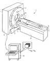
図1は角度をずらされて配置された2つの焦点−検出器システムを備えたCTシステムの3D概略図を示し、
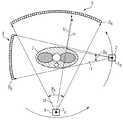
図2は図1によるCTシステムの概略横断面図を示し、
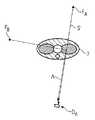
図3は患者を通る直接放射線と角度をずらされた焦点からの同時の散乱放射線成分とを簡略的に表示し、
図4は図3の表示を180°角度をずらして示し、
図5は直接の平行投影の散乱放射線とこれに対して相補関係にある平行投影の散乱放射線との強度経過を差形成の経過を含めて示す。In the following, the invention will be described in detail with reference to the drawings on the basis of advantageous embodiments. Only the features necessary for an understanding of the invention are shown here.
FIG. 1 shows a 3D schematic diagram of a CT system with two focus-detector systems arranged at offset angles;
FIG. 2 shows a schematic cross-sectional view of the CT system according to FIG.
FIG. 3 shows a simplified representation of the direct radiation through the patient and the simultaneous scattered radiation components from the off-focus point,
FIG. 4 shows the display of FIG.
FIG. 5 shows the intensity course of the scattered radiation of direct parallel projection and that of the parallel projection in a complementary relationship, including the course of difference formation.
図では次の符号が使用されている。1:CTシステム、2:第1のX線管、3:第1の検出器システム、4:第2のX線管、5:第2の検出器システム、6:ガントリハウジング、7:患者、8:移動可能な患者用寝台、9:システム軸線、10:制御および計算ユニット、11:X線管2のファン状放射線、12:X線管4のファン状放射線(ファンビーム)、13:直接投影pの散乱放射線の強度経過、14:相補投影p’の散乱放射線の強度経過、15:直接投影pと相補投影p’との間のチャネルごとの差、Prg1〜Prgn:本発明による方法を実行するためのプログラム、I:強度、I0:初期強度、S:直接放射線、S':相補放射線、FA:焦点−検出器システムFDSAの焦点、FB:焦点−検出器システムFDSBの焦点、DA:焦点−検出器システムFDSAの検出器、DB:焦点−検出器システムFDSBの検出器、Δ:相補放射線S'の散乱放射線成分、βA:焦点−検出器システムFDSAのファン角、βB:焦点−検出器システムSDSBのファン角。The following symbols are used in the figure. 1: CT system, 2: first X-ray tube, 3: first detector system, 4: second X-ray tube, 5: second detector system, 6: gantry housing, 7: patient, 8: movable patient bed, 9: system axis, 10: control and calculation unit, 11: fan-like radiation of
図1は、第1のX線管2および対向する検出器3を有する第1の焦点−検出器システムFDSAと、第2のX線管4および対向する検出器5を有する第2の焦点−検出器システムFDSBとの2つの焦点−検出器システムを備えた模範的なコンピュータ断層撮影システムを示す。焦点−検出器システム2,3および4,5は、ガントリハウジング6内のここでは明示されていないガントリ上に、90°角度をずらされて配置され、患者の走査時にシステム軸線9の周りを移動させられ、一方患者7は連続的または逐次的に走査範囲を通して送り込まれる。このために長手方向に移動可能な患者用寝台8が役立ち、患者用寝台8は制御および計算ユニット10によって制御される。制御および計算ユニット10は、焦点−検出器システム2,3および4,5を有するガントリの制御および運転も担当する。更に、この制御および計算ユニット10において、両焦点−検出器システムによって得られる吸収データが収集され、これにより公知の再構成法によってCT画像データセットもしくはCTボリュームデータセットに変換される。このために、模範的に示されたプログラムPrg1〜Prgnが使用される。これらのプログラムにおいて本発明によるステップも描出される。FIG. 1 shows a first focus with a
2つの焦点−検出器システムを備えたこの種のCTシステムにおける横散乱の問題点のよりよい理解のために図2の概略図が役立つ。大まかに図示された内部構造を有する患者7が示されている。患者7は、焦点FAおよび検出器DAを有する焦点−検出器システムFDSAと、これに対し90°ずらされて配置された焦点FBおよび検出器DBを有する焦点−検出器システムFDSBとの2つの焦点−検出器システムによって走査される。図1に対する良好な位置確認を行うために、付設の両X線管2,4が示されている。ここでは1列の検出素子としてのみ示されている検出器DAもしくはDBには符号5もしくは3が付されている。使用されたファン状放射線(ファンビーム)のファン角がβAもしくはβBで示され、焦点FAもしくはFBからコーン状放射線(コーンビーム)12,11が形成される。The schematic diagram of FIG. 2 is useful for a better understanding of the problem of transverse scattering in this type of CT system with two focus-detector systems. A
両焦点−検出器システムの回転方向は矢印によって示されている。 The direction of rotation of the bifocal-detector system is indicated by arrows.
焦点FAから出て検出器DAの1つの検出素子に至る直接放射線を考察するに、両焦点−検出器システムが動作中であるならば、同時に、放射線Sの強度Iを測定する同じ検出素子において測定された強度に同様に寄与する散乱放射線Δが発生する。この場合に、本発明者は、散乱放射線の主成分は走査された対象の表面層からほとんど出るので、患者の全ての深部層からは放射線Sに対して平行な散乱放射線はほとんど発生せず、むしろ主に患者の検出器DA側の側面に散乱放射線成分が発生することを認識した。このジオメトリ状態に基づいて、平行投影の観察時に多数のチャネルにわたって見た散乱放射線成分は、例えば図5に曲線13でもしくはこれに対して相補関係にある曲線14で示されているように、非対称の経過を有する。Considering the direct radiation leaving the focal point FA and going to one detector element of the detector DA , the same detection measuring the intensity I of the radiation S at the same time if the bifocal-detector system is in operation. Scattered radiation Δ is generated which likewise contributes to the intensity measured at the device. In this case, the inventor found that the main component of the scattered radiation almost comes out of the surface layer of the scanned object, so that almost no scattered radiation parallel to the radiation S is generated from all the deep layers of the patient. rather primarily scattered radiation component to the side of the detector Da side of the patient recognizes the occurrence. Based on this geometry state, the scattered radiation component seen across multiple channels when viewing parallel projections is asymmetrical, as shown, for example, by
ここで焦点FAから出て検出器DAの1つの検出素子に至る図3の1つの単独の走査放射線Sを考察し、90°ずらされた焦点FBから発生される散乱放射線が主としてどこで生じるかを熟考するならば、図3に散乱放射線成分Δの破線により示されているような散乱放射線の主要発生位置がもたらされる。Now consider one single scanning radiation S in FIG. 3 from the focal point FA and leading to one detector element of the detector DA , where the scattered radiation generated from the focal point FB shifted 90 ° is mainly where. If one considers what happens, the main location of the scattered radiation as shown in FIG. 3 by the dashed line of the scattered radiation component Δ is provided.
これに対して図4は、両焦点−検出器システムが180°回転した後に、相補関係で経過する放射線S’を示す。この放射線に関する減弱を考察する場合、放射線S’は、本来的には図3の放射線Sと同じ強度Iを有するはずである。しかしながら、図4における焦点FBは異なる側に配置され、FBからDAへの破線で示された放射線経路を介する散乱放射線が著しく僅かな強度を有するために、放射線Sとこれに対して相補に配置された相補放射線S’との両強度の差形成から図3において測定される散乱放射線の主たる成分が決定される。In contrast, FIG. 4 shows the radiation S ′ that passes in a complementary relationship after the bifocal-detector system has rotated 180 °. When considering the attenuation associated with this radiation, the radiation S ′ should essentially have the same intensity I as the radiation S of FIG. However, the focal point FB in FIG. 4 is located on a different side, and the scattered radiation through the radiation path indicated by the broken line from FB to DA has a significantly lower intensity, so that the radiation S and The main component of the scattered radiation measured in FIG. 3 is determined from the difference between the two intensities of the complementary radiation S ′ arranged in a complementary manner.
このようにして、基本的に全ての放射線において、(180°移動された同じ検出器システムで測定された)直接放射線Sとこれに対する相補放射線S’との間の差が形成される。直接放射線Sの強度Iが相補放射線S’の強度I’よりも大きい場合には常に、この成分が散乱放射線成分であるということが前提であるので、この成分が放射線Sの強度Iから引き算されるとよい。 In this way, the difference between the direct radiation S (measured with the same detector system moved by 180 °) and the complementary radiation S 'is formed in essentially all radiation. It is assumed that this component is a scattered radiation component whenever the intensity I of the direct radiation S is greater than the intensity I ′ of the complementary radiation S ′, so that this component is subtracted from the intensity I of the radiation S. Good.
確かに、この方法によって100%全ての散乱放射線成分を測定データから除去することができるというわけではないが、最も大きな成分はこの計算方法によって消去される。 Certainly not 100% of all scattered radiation components can be removed from the measurement data by this method, but the largest component is eliminated by this calculation method.
図5は、直接および間接の平行投影の散乱放射線のモンテカルロシミュレーションによって計算された経過を示す。横軸にはチャネルが、そして縦軸には測定された強度Iが任意の単位で取られている。直接投影の散乱放射線の経過は符号13で示され、これに対する相補の散乱放射線の強度は経過14で示されている。ここに示された負の強度は反対側に配置されている強度であることを表しているにすぎず、本来の強度測定はもちろん正のみの強度で発生する。両強度13,14間の差を形成すると、曲線15が得られる。本発明によれば、曲線15の正の値の全てが、直接投影の測定された強度から差し引かれ、それにより散乱放射線補正が行なわれる。この場合にこの曲線15の負の成分は考慮対象外である。 FIG. 5 shows the course calculated by Monte Carlo simulation of scattered radiation of direct and indirect parallel projection. The horizontal axis represents the channel, and the vertical axis represents the measured intensity I in arbitrary units. The direct projection of the scattered radiation is shown at 13 and the complementary scattered radiation intensity is shown at 14. The negative intensity shown here only indicates that the intensity is located on the opposite side, and the original intensity measurement naturally occurs with only positive intensity. When the difference between the two
以上のとおり、本発明により、回転可能なガントリ上に互いに角度をずらされて配置されかつ同時に動作させられる2つの焦点−検出器システムを備えたCTシステムの放射補正方法が提案される。この提案された方法では、対象の走査のために、互いに角度をずらされて配置された2つの焦点−検出器システムがCTシステムのシステム軸線の周りを回転することによって対象を走査し、焦点の放射の測定された減弱から個々の放射線の複数の吸収値が決定され、測定された値が散乱放射線補正を受け、直接放射線Sについて、直接放射線Sの強度値Iと180°離れた相補放射線S’の強度値I’とからなる正の差がチャネルごとに求められ、この正の差Δ=I−I’が散乱放射線補正として直接放射線Sの強度値Iから引き算され、それにより減弱値が決定され、この減弱値から公知のようにCTスライス画像またはCTボリュームデータが再構成される。 As described above, the present invention proposes a radiation correction method for a CT system comprising two focus-detector systems that are arranged at different angles on a rotatable gantry and are operated simultaneously. In this proposed method, for focus scanning, two focus-detector systems arranged at an angle to each other scan the target by rotating around the system axis of the CT system, From the measured attenuation of the radiation, a plurality of absorption values of the individual radiation are determined, the measured values are subjected to scattered radiation correction, and for the direct radiation S, the complementary radiation S 180 ° away from the intensity value I of the direct radiation S. A positive difference consisting of 'intensity value I' is determined for each channel, and this positive difference Δ = I−I ′ is directly subtracted from the intensity value I of the radiation S as a scattered radiation correction, so that the attenuation value is From this attenuation value, a CT slice image or CT volume data is reconstructed in a known manner.
本発明の上述の特徴は、その都度述べた組み合わせだけでなく、本発明の範囲を逸脱することなしに他の組み合わせまたは単独で使用可能である。 The above-described features of the present invention can be used not only in the combinations described above, but also in other combinations or alone without departing from the scope of the present invention.
以上のとおり、本発明によって、回転可能なガントリ上に互いに角度をずらされて配置された2つの焦点−検出器システムが同時に動作させられるCTシステムの放射補正のために、互いに角度をずらされて配置された2つの焦点−検出器システムがCTシステムのシステム軸線の周りを回転することによって対象を走査し、焦点の放射の測定された減弱から個々の放射線の複数の吸収値が決定され、測定された値が散乱放射線補正を受け、直接放射線Sについて、直接放射線の強度値と180°離れた相補放射線の強度値とからなる正の差がチャネルごとに求められ、この正の差が散乱放射線補正として直接放射線の強度値から引き算されることにより、実際の減弱値が決定され、この減弱値から公知のようにCTスライス画像またはCTボリュームデータを再構成される。 As described above, according to the present invention, an angle is shifted with respect to each other for radiation correction of a CT system in which two focus-detector systems arranged at an angle relative to each other on a rotatable gantry are operated simultaneously. Two positioned focus-detector systems scan the object by rotating around the system axis of the CT system, and from the measured attenuation of the focus radiation, multiple absorption values of the individual radiation are determined and measured The obtained value is subjected to the scattered radiation correction, and for the direct radiation S, a positive difference between the direct radiation intensity value and the complementary radiation intensity value 180 ° apart is obtained for each channel, and this positive difference is determined by the scattered radiation. By subtracting directly from the intensity value of the radiation as a correction, an actual attenuation value is determined, from which the CT slice image or CT is known as is known. Reconfigured the Liu-time data.
1 CTシステム
2 第1の焦点
3 第1の検出器システム
4 第2の焦点
5 第2の検出器システム
6 ガントリハウジング
7 患者
8 移動可能な患者用寝台
9 システム軸線
10 制御および計算ユニット
11 X線管2のファン状放射線
12 X線管4のファン状放射線
13 直接投影pの散乱放射線の強度経過
14 相補投影p’の散乱放射線の強度経過
15 直接投影pと相補投影p’との間のチャネルごとの差
Prg1〜Prgn 本発明による方法を実行するためのプログラム
I 強度
I0 初期強度
S 直接放射線
S' 相補放射線
FA 焦点−検出器システムFDSAの焦点
FB 焦点−検出器システムFDSBの焦点
DA 焦点−検出器システムFDSAの検出器
DB 焦点−検出器システムFDSBの検出器
Δ 相補放射線S'の散乱放射線成分
βA 焦点−検出器システムFDSAのファン角
βB 焦点−検出器システムSDSBのファン角DESCRIPTION OF
Claims (8)
Translated fromJapanese互いに角度をずらされて配置された焦点−検出器システム(FDSA,FDSB)がCTシステム(1)のシステム軸線(9)の周りを回転することによって対象(7)を走査し、焦点(FA,FB)の放射の測定された減弱から個々の放射線(S)の複数の吸収値(a)が決定され、
求められた吸収データにより対象のCT画像またはCTボリュームデータが再構成されるコンピュータ断層撮影システムの散乱放射線補正方法において、
1つの焦点−検出器システム(FDSA,FDSB)の各直接放射線(S)について、180°移動された同じ焦点−検出器システム(FDSA,FDSB)の反対向きの相補放射線(S’)が探索され、この相補放射線(S’)が検出器データから直接に得られない場合には、この焦点−検出器システム(FDSA,FDSB)の空間的に類似した位置および方位を有する放射線の吸収データによる補間によって求められ、
各直接放射線(S)の減弱された強度値(I)から相補放射線(S’)の強度値(I’)が引き算され、
直接放射線(S)の強度値(I)と相補放射線(S’)の強度値(I’)との差の正の成分が、散乱放射線成分(Δ)として解釈されて、直接放射線(S)の強度値(I)から引き算され、それから直接放射線(S)の補正された吸収値(akorr)が決定され、
補正された吸収値(akorr)からCT画像またはCTボリュームデータが再構成される
ことを特徴とするコンピュータ断層撮影システムの散乱放射線補正方法。For the correction of scattered radiation in a computed tomography (CT) system with two focus-detector systems (FDSA, FDSB), which are arranged at different angles on a rotatable gantry and are operated simultaneously,
A focus-detector system (FDSA, FDSB), arranged at an angle to each other, scans the object (7) by rotating around the system axis (9) of the CT system (1), and the focus (FA , FB ) from the measured attenuation of the radiation, a plurality of absorption values (a) of the individual radiation (S) are determined,
In a scattered radiation correction method for a computed tomography system in which a target CT image or CT volume data is reconstructed from the obtained absorption data,
For each direct radiation (S) of one focus-detector system (FDSA, FDSB), the opposite complementary radiation (S ′) of the same focus-detector system (FDSA, FDSB) moved 180 ° is searched. If this complementary radiation (S ′) is not obtained directly from the detector data, interpolation with the absorption data of radiation having spatially similar positions and orientations of this focus-detector system (FDSA, FDSB) Sought by
The intensity value (I ′) of the complementary radiation (S ′) is subtracted from the attenuated intensity value (I) of each direct radiation (S),
The positive component of the difference between the intensity value (I) of the direct radiation (S) and the intensity value (I ′) of the complementary radiation (S ′) is interpreted as the scattered radiation component (Δ), and the direct radiation (S). From which the corrected absorption value (akorr ) of the radiation (S) is directly determined,
A scattered radiation correction method for a computed tomography system, wherein a CT image or CT volume data is reconstructed from the corrected absorption value (akorr ).
互いに角度をずらされて配置された焦点−検出器システム(FDSA,FDSB)がCTシステム(1)のシステム軸線(9)の周りを回転することによって対象(7)を走査し、焦点(FA,FB)の放射の測定された減弱から、対象(7)によって減弱された強度値(I)および減弱されない強度値(I0)から算出された吸収値(p=−ln(I/I0))からなる複数の平行投影が作成され、そして測定された値が散乱放射線補正を受け、
平行投影により対象(7)のCT画像が再構成されるコンピュータ断層撮影システムの散乱放射線補正方法において、
もっぱら1つの焦点−検出器システム(FDSA,FDSB)の同じ方向に測定された吸収データ(a)に由来する1つの焦点−検出器システム(FDSA,FDSB)の各直接平行投影(p)について、同じ焦点−検出器システム(FDSA,FDSB)の反対向きの相補平行投影(P’)が探索され、この相補平行投影(P’)が検出器データから直接に得られない場合には、同じ焦点−検出器システム(FDSA,FDSB)の空間的に類似した位置および方位を有する放射線の吸収データによる補間によって補間され、
各直接平行投影(p)の減弱された強度値(I)からチャネルごとに相補平行投影(p’)の減弱された強度値(I’)が引き算され、
チャネルごとに存在する正符号を持つ差が、散乱放射線成分(Δ)として解釈されて、散乱放射線補正のためにチャネルごとに直接平行投影(p)から引き算され、
補正された吸収値(akorr)からCT画像またはCTボリュームデータが再構成される
ことを特徴とするコンピュータ断層撮影システムの散乱放射線補正方法。For the correction of scattered radiation in a computed tomography (CT) system with two focus-detector systems (FDSA, FDSB), which are arranged at different angles on a rotatable gantry and are operated simultaneously,
A focus-detector system (FDSA, FDSB), arranged at an angle to each other, scans the object (7) by rotating around the system axis (9) of the CT system (1), and the focus (FA , FB ) from the measured attenuation of the emission, the absorption value (p = −ln (I / I) calculated from the intensity value (I) attenuated by the subject (7) and the intensity value (I0 ) not attenuated.0 )) are created, and the measured values are subjected to scattered radiation correction,
In a scattered radiation correction method for a computed tomography system in which a CT image of an object (7) is reconstructed by parallel projection,
For each direct parallel projection (p) of one focus-detector system (FDSA, FDSB) derived exclusively from absorption data (a) measured in the same direction of one focus-detector system (FDSA, FDSB), Opposite parallel projections (P ′) of the same focus-detector system (FDSA, FDSB) are searched, and if this complementary parallel projection (P ′) is not directly obtained from the detector data, the same focus Interpolated by interpolation with absorption data of radiation having spatially similar position and orientation of the detector system (FDSA, FDSB),
The attenuated intensity value (I ′) of the complementary parallel projection (p ′) is subtracted for each channel from the attenuated intensity value (I) of each direct parallel projection (p),
The difference with the positive sign present for each channel is interpreted as the scattered radiation component (Δ) and subtracted from the direct parallel projection (p) for each channel for correction of scattered radiation,
A scattered radiation correction method for a computed tomography system, wherein a CT image or CT volume data is reconstructed from the corrected absorption value (akorr ).
Applications Claiming Priority (1)
| Application Number | Priority Date | Filing Date | Title |
|---|---|---|---|
| DE102005048388ADE102005048388B4 (en) | 2005-10-10 | 2005-10-10 | Method for radiation correction of a CT system |
Publications (1)
| Publication Number | Publication Date |
|---|---|
| JP2007105467Atrue JP2007105467A (en) | 2007-04-26 |
Family
ID=37896272
Family Applications (1)
| Application Number | Title | Priority Date | Filing Date |
|---|---|---|---|
| JP2006274806AAbandonedJP2007105467A (en) | 2005-10-10 | 2006-10-06 | Scattered radiation correction method for computer tomography system and computer tomography system |
Country Status (4)
| Country | Link |
|---|---|
| US (1) | US20070081622A1 (en) |
| JP (1) | JP2007105467A (en) |
| CN (1) | CN1954779A (en) |
| DE (1) | DE102005048388B4 (en) |
Cited By (1)
| Publication number | Priority date | Publication date | Assignee | Title |
|---|---|---|---|---|
| JP2009082616A (en)* | 2007-10-02 | 2009-04-23 | Toshiba Corp | Method for scaling scattered ray intensity distribution in multi-tube X-ray CT and multi-tube X-ray CT apparatus |
Families Citing this family (16)
| Publication number | Priority date | Publication date | Assignee | Title |
|---|---|---|---|---|
| RU2438579C2 (en)* | 2006-05-26 | 2012-01-10 | Конинклейке Филипс Электроникс, Н.В. | Reconstruction in system with several tubes |
| US8180029B2 (en)* | 2007-06-28 | 2012-05-15 | Voxer Ip Llc | Telecommunication and multimedia management method and apparatus |
| US11095583B2 (en) | 2007-06-28 | 2021-08-17 | Voxer Ip Llc | Real-time messaging method and apparatus |
| US9178916B2 (en) | 2007-06-28 | 2015-11-03 | Voxer Ip Llc | Real-time messaging method and apparatus |
| US20110019662A1 (en)* | 2007-06-28 | 2011-01-27 | Rebelvox Llc | Method for downloading and using a communication application through a web browser |
| CN102160085B (en)* | 2008-09-16 | 2013-11-20 | 皇家飞利浦电子股份有限公司 | Imaging apparatus including correction unit for scattered radiation |
| WO2010073308A1 (en)* | 2008-12-22 | 2010-07-01 | 三菱重工業株式会社 | Radiation tomography |
| DE102009057716A1 (en)* | 2009-12-10 | 2011-06-16 | Siemens Aktiengesellschaft | Noise reduction with dual-source CT recordings |
| US9271689B2 (en) | 2010-01-20 | 2016-03-01 | General Electric Company | Apparatus for wide coverage computed tomography and method of constructing same |
| DE102011005750B4 (en)* | 2011-03-18 | 2012-11-15 | Siemens Aktiengesellschaft | Method and computer tomograph for determining the distance of an examination object from the focus of a computer tomograph |
| DE102011006579A1 (en)* | 2011-03-31 | 2012-10-04 | Siemens Aktiengesellschaft | Method for generating image data of an examination object, projection data processing device, X-ray system and computer program |
| DE102013200400A1 (en)* | 2012-09-24 | 2014-05-28 | Siemens Aktiengesellschaft | Method and device for determining the attenuation of the X-radiation caused by the object to be examined |
| WO2018227523A1 (en)* | 2017-06-16 | 2018-12-20 | Shanghai United Imaging Healthcare Co., Ltd. | Systems and methods for image data processing in computerized tomography |
| CN112971823B (en)* | 2017-08-31 | 2023-12-01 | 上海联影医疗科技股份有限公司 | Method for correcting stray rays |
| US11435419B2 (en)* | 2018-05-10 | 2022-09-06 | Siemens Healthcare Gmbh | Streak artifact reduction in magnetic resonance imaging |
| US12412321B2 (en)* | 2021-12-30 | 2025-09-09 | Canon Medical Systems Corporation | Method and system to compensate for consecutive missing views in computed tomography (CT) reconstruction |
Family Cites Families (5)
| Publication number | Priority date | Publication date | Assignee | Title |
|---|---|---|---|---|
| US4206359A (en)* | 1974-01-31 | 1980-06-03 | E M I Limited | Radiography |
| DE10232429B3 (en)* | 2002-07-17 | 2004-01-22 | Siemens Ag | Method for an x-ray arrangement for compensating for scattered radiation and x-ray device |
| JP4314008B2 (en)* | 2002-10-01 | 2009-08-12 | 株式会社東芝 | X-ray CT scanner |
| DE10302567A1 (en)* | 2003-01-22 | 2004-08-12 | Siemens Ag | Medical diagnostic X-ray computer tomography unit has at least two beam detector units that are operated in an alternating manner |
| JP4334244B2 (en)* | 2003-02-13 | 2009-09-30 | 株式会社東芝 | Biplane X-ray equipment |
- 2005
- 2005-10-10DEDE102005048388Apatent/DE102005048388B4/ennot_activeExpired - Fee Related
- 2006
- 2006-10-06JPJP2006274806Apatent/JP2007105467A/ennot_activeAbandoned
- 2006-10-06USUS11/543,930patent/US20070081622A1/ennot_activeAbandoned
- 2006-10-10CNCNA2006101495276Apatent/CN1954779A/enactivePending
Cited By (1)
| Publication number | Priority date | Publication date | Assignee | Title |
|---|---|---|---|---|
| JP2009082616A (en)* | 2007-10-02 | 2009-04-23 | Toshiba Corp | Method for scaling scattered ray intensity distribution in multi-tube X-ray CT and multi-tube X-ray CT apparatus |
Also Published As
| Publication number | Publication date |
|---|---|
| DE102005048388A1 (en) | 2007-04-19 |
| DE102005048388B4 (en) | 2007-07-26 |
| US20070081622A1 (en) | 2007-04-12 |
| CN1954779A (en) | 2007-05-02 |
Similar Documents
| Publication | Publication Date | Title |
|---|---|---|
| JP2007105467A (en) | Scattered radiation correction method for computer tomography system and computer tomography system | |
| JP2007144134A (en) | Scattered radiation correction method for computer tomography system and computer tomography system | |
| US11497459B2 (en) | Methods and system for optimizing an imaging scan based on a prior scan | |
| JP5980486B2 (en) | System and method for visualization and quantification of vascular stenosis using spectral CT analysis | |
| US20100308229A1 (en) | Movable wedge for improved image quality in 3d x-ray imaging | |
| JP2007296338A (en) | Method for correcting scattered radiation in X-ray computed tomography apparatus and X-ray computed tomography apparatus | |
| JP2007296340A (en) | Scattered radiation correction method and computed tomography system for a computed tomography system with at least two focus-detector systems arranged at different angles | |
| JP2007300964A (en) | Radiographic equipment and radiography method | |
| CN102727234B (en) | Produce to check the method for the view data of object, process device and x-ray system | |
| US9592021B2 (en) | X-ray CT device, and method | |
| JP2009082616A (en) | Method for scaling scattered ray intensity distribution in multi-tube X-ray CT and multi-tube X-ray CT apparatus | |
| EP3835830B1 (en) | Systems and methods for estimating a focal spot motion and calculating a corresponding correction | |
| CN112807006A (en) | System and method for coherent scatter imaging using segmented photon counting detectors for computed tomography | |
| US7822253B2 (en) | Methods and apparatus for BMD measuring | |
| US7327824B2 (en) | Radiation tomography apparatus and radiation tomography method thereof | |
| US9901314B2 (en) | Adjustable bow-tie filter for achieving optimal SNR in helical computed tomography | |
| KR100685561B1 (en) | X-ray CT device and imaging method | |
| JP5027909B2 (en) | X-ray CT system | |
| JP5595724B2 (en) | X-ray CT system | |
| JP2007282740A (en) | X-ray ct apparatus | |
| JP5097384B2 (en) | X-ray CT apparatus and scatter correction method | |
| JP4644292B2 (en) | X-ray CT apparatus and image display method thereof | |
| JP4648355B2 (en) | Tube current adjusting method and apparatus, and X-ray CT apparatus | |
| JP6183884B2 (en) | Radiation tomography apparatus, projection data correction method, and program | |
| JP4509507B2 (en) | Radiation calculation tomographic image apparatus and tomographic image generation method |
Legal Events
| Date | Code | Title | Description |
|---|---|---|---|
| A621 | Written request for application examination | Free format text:JAPANESE INTERMEDIATE CODE: A621 Effective date:20070319 | |
| A762 | Written abandonment of application | Free format text:JAPANESE INTERMEDIATE CODE: A762 Effective date:20080107 |