JP2007104603A - Portable sound driver - Google Patents
Portable sound driverDownload PDFInfo
- Publication number
- JP2007104603A JP2007104603AJP2005295636AJP2005295636AJP2007104603AJP 2007104603 AJP2007104603 AJP 2007104603AJP 2005295636 AJP2005295636 AJP 2005295636AJP 2005295636 AJP2005295636 AJP 2005295636AJP 2007104603 AJP2007104603 AJP 2007104603A
- Authority
- JP
- Japan
- Prior art keywords
- magnetostrictive actuator
- unit
- state
- housing
- diaphragm
- Prior art date
- Legal status (The legal status is an assumption and is not a legal conclusion. Google has not performed a legal analysis and makes no representation as to the accuracy of the status listed.)
- Abandoned
Links
Images


Classifications
- H—ELECTRICITY
- H04—ELECTRIC COMMUNICATION TECHNIQUE
- H04R—LOUDSPEAKERS, MICROPHONES, GRAMOPHONE PICK-UPS OR LIKE ACOUSTIC ELECTROMECHANICAL TRANSDUCERS; DEAF-AID SETS; PUBLIC ADDRESS SYSTEMS
- H04R3/00—Circuits for transducers, loudspeakers or microphones
- H—ELECTRICITY
- H04—ELECTRIC COMMUNICATION TECHNIQUE
- H04R—LOUDSPEAKERS, MICROPHONES, GRAMOPHONE PICK-UPS OR LIKE ACOUSTIC ELECTROMECHANICAL TRANSDUCERS; DEAF-AID SETS; PUBLIC ADDRESS SYSTEMS
- H04R15/00—Magnetostrictive transducers
Landscapes
- Physics & Mathematics (AREA)
- Engineering & Computer Science (AREA)
- Acoustics & Sound (AREA)
- Signal Processing (AREA)
- Details Of Audible-Bandwidth Transducers (AREA)
- Telephone Function (AREA)
- Circuit For Audible Band Transducer (AREA)
Abstract
Description
Translated fromJapaneseこの発明は、音声信号に基づいて駆動される磁歪アクチュエータを備える携帯音声駆動装置に関する。 The present invention relates to a portable audio drive device including a magnetostrictive actuator driven based on an audio signal.
詳しくは、この発明は、磁歪アクチュエータを、駆動ロッドの変位を伝達する変位伝達部が筐体より突出した状態で、あるいはその変位伝達部が筐体より突出可能に、配設することによって、変位伝達部を所定の振動板に当接させて音声出力を得ることができ、携帯性を保ちながら、充分な音量を得ることができるようにした携帯音声駆動装置に係るものである。 Specifically, according to the present invention, the magnetostrictive actuator is displaced by disposing the displacement transmitting portion that transmits the displacement of the drive rod from the housing, or such that the displacement transmitting portion can protrude from the housing. The present invention relates to a portable voice drive device that can obtain a sound output by bringing a transmission portion into contact with a predetermined diaphragm and can obtain a sufficient sound volume while maintaining portability.
従来、例えば特許文献1等に記載されているように、磁歪アクチュエータで振動板を駆動して音声出力を得る音声出力装置が知られている。磁歪アクチュエータとは、外部磁界を与えると形状が変化する磁歪素子を使用したアクチュエータである。 2. Description of the Related Art Conventionally, as described in
図33は、この種の音声出力装置300の構成例を示している。この音声出力装置300は、プレーヤ301、アンプ302、磁歪アクチュエータ303および振動板304からなっている。 FIG. 33 shows a configuration example of this type of
プレーヤ301は、例えばCD(Compact Disc)、MD(Mini Disc)、DVD(Digital Versatile Disc)等を再生して音声信号を出力する。このプレーヤ301から出力される音声信号はアンプ302で増幅された後に磁歪アクチュエータ303に供給される。磁歪アクチュエータ303は、変位出力を伝達する駆動ロッド303aを有しており、この駆動ロッド303aの先端が振動板304に当接されている。 The
磁歪アクチュエータ303は、音声信号に基づいて、振動板304を駆動する。すなわち、磁歪アクチュエータ303の駆動ロッド303aが音声信号波形に対応して変位し、その変位が振動板304に伝達される。これにより、振動板304からは、音声信号に対応した音声が出力される。 The
磁歪アクチュエータは、形状が変化する際の発生応力が大きいため、たとえ磁歪アクチュエータが小型であっても、振動させる振動板によっては、比較的大音量で鳴らすことができ、また比較的硬い振動板(鉄板など)でさえも鳴らすことができる。また、この磁歪アクチュエータは応答速度にも優れ、磁歪素子単体はnsecオーダーで動作する。 The magnetostrictive actuator generates a large amount of stress when its shape changes. Therefore, even if the magnetostrictive actuator is small, depending on the diaphragm to be vibrated, it can be sounded at a relatively large volume, and a relatively hard diaphragm ( Even iron plates etc. can be sounded. Further, this magnetostrictive actuator is excellent in response speed, and the magnetostrictive element alone operates on the order of nsec.
ここで、携帯性のあるスピーカシステムを考える。一般的なスピーカでは、音量に相当する大きさのスピーカ径が必要となる。携帯性を重視し、小型化、軽量化を考えたときは、スピーカ径を小さくすることになる。しかしその場合には、充分な音量を確保できなくなる。つまり、携帯性と音量とはトレードオフの関係にある。 Here, a portable speaker system is considered. A general speaker requires a speaker diameter having a size corresponding to the volume. When portability is emphasized and miniaturization and weight reduction are considered, the speaker diameter is reduced. However, in that case, sufficient volume cannot be secured. That is, portability and volume are in a trade-off relationship.
この発明の目的は、携帯性を保ちながら、充分な音量を得ることができる携帯音声駆動装置を提供することにある。 An object of the present invention is to provide a portable audio drive device capable of obtaining a sufficient volume while maintaining portability.
この発明の概念は、
音声信号を出力する音声信号出力部と、
上記音声信号出力部から出力される音声信号に基づいて駆動される磁歪アクチュエータとを備え、
上記磁歪アクチュエータは、駆動ロッドの変位を伝達する変位伝達部が筐体より突出した状態で、あるいは該変位伝達部が筐体より突出可能に配設されている
ことを特徴とする携帯音声駆動装置にある。The concept of this invention is
An audio signal output unit for outputting an audio signal;
A magnetostrictive actuator driven based on the audio signal output from the audio signal output unit,
The magnetostrictive actuator is characterized in that a displacement transmission part for transmitting displacement of a drive rod protrudes from the casing, or the displacement transmission part is arranged to protrude from the casing. It is in.
この発明においては、磁歪アクチュエータを備えている。この磁歪アクチュエータは、音声信号出力部から出力される音声信号に基づいて駆動される。例えば、携帯音声駆動装置がHDD(Hard Disk Drive)プレーヤであれば、磁歪アクチュエータは、HDDから読み出された圧縮音声データが伸長処理されて得られた音声信号で駆動される。また例えば、携帯音声駆動装置が携帯電話機であれば、磁歪アクチュエータは、音声処理部で圧縮音声データが伸長処理されて得られた音声信号で駆動される。 In the present invention, a magnetostrictive actuator is provided. The magnetostrictive actuator is driven based on the audio signal output from the audio signal output unit. For example, if the portable audio drive device is an HDD (Hard Disk Drive) player, the magnetostrictive actuator is driven by an audio signal obtained by decompressing compressed audio data read from the HDD. Further, for example, if the portable audio driving device is a mobile phone, the magnetostrictive actuator is driven by an audio signal obtained by decompressing the compressed audio data by the audio processing unit.
この磁歪アクチュエータは、駆動ロッドの変位を伝達する変位伝達部が筐体より突出した状態で配設される。あるいは、この磁歪アクチュエータは、変位伝達部が筐体より突出可能に配設される。この場合、筐体から突出した変位伝達部を所定の振動板に当接させることで、この振動板を振動させて音声出力を得ることができる。 This magnetostrictive actuator is disposed in a state in which a displacement transmitting portion for transmitting the displacement of the drive rod protrudes from the housing. Alternatively, the magnetostrictive actuator is arranged such that the displacement transmitting portion can protrude from the housing. In this case, by bringing the displacement transmitting portion protruding from the housing into contact with the predetermined diaphragm, the diaphragm can be vibrated to obtain an audio output.
ここで、磁歪アクチュエータは、例えば、一の面が振動板で構成されている小筐体に、駆動ロッドが一の面に当接された状態で収納されているか、駆動ロッドの変位を拡大する変位拡大器に取り付けられているか、あるいは小筐体に収納されてもおらず、変位拡大器に取り付けられてもいない、いわゆるむき出し状態におかれる。 Here, for example, the magnetostrictive actuator is housed in a small housing whose one surface is made of a diaphragm with the drive rod in contact with the one surface, or enlarges the displacement of the drive rod. It is attached to the displacement expander, or it is placed in a so-called bare state that is not housed in a small housing and is not mounted on the displacement expander.
磁歪アクチュエータが小筐体に収納されている場合、変位伝達部は振動板で構成される一の面である。また、磁歪アクチュエータが変位拡大器に取り付けられている場合、変位伝達部は変位拡大器である。また、磁歪アクチュエータがむき出し状態にある場合、変位伝達部は駆動ロッドである。 When the magnetostrictive actuator is housed in a small housing, the displacement transmitting unit is one surface constituted by a diaphragm. Further, when the magnetostrictive actuator is attached to the displacement magnifier, the displacement transmission unit is a displacement magnifier. When the magnetostrictive actuator is in an exposed state, the displacement transmitting unit is a drive rod.
この発明の携帯音声駆動装置は、変位伝達部が当接される所定の振動板が大きいときには充分な音量を得ることができ、しかも充分な音量を得るために大きな振動板を備えるものではなく携帯性を保つことができる。ここで、駆動ロッドが筐体より突出可能に配設される場合には、この駆動ロッドを所定の振動板に当接させて音声出力を得るときだけ、当該駆動ロッドを筐体から突出した状態とでき、その他のときに駆動ロッドの突出が邪魔になることを回避できる。 The portable audio drive device of the present invention can obtain a sufficient volume when the predetermined diaphragm with which the displacement transmitting portion is in contact is large, and is not equipped with a large diaphragm to obtain a sufficient volume. Can keep sex. Here, when the drive rod is disposed so as to be able to protrude from the housing, the drive rod protrudes from the housing only when the drive rod is brought into contact with a predetermined diaphragm to obtain sound output. In other cases, it can be avoided that the protrusion of the drive rod becomes an obstacle.
例えば、筐体は、変位伝達部を所定の振動板に当接した状態で、この所定の振動板に吸着するための吸盤を有するものとされる。この吸盤によって筐体を所定の振動板に吸着させておくことで、変位伝達部が所定の振動板に当接した状態を保持でき、ユーザが変位伝達部を所定の振動板に当接した状態を保持するように筐体を持ち続けることは必要なく、使い勝手が向上する。 For example, the housing has a suction cup for adsorbing to the predetermined vibration plate in a state where the displacement transmission unit is in contact with the predetermined vibration plate. A state in which the displacement transmission unit is in contact with the predetermined vibration plate can be maintained by adsorbing the housing to the predetermined vibration plate by the suction cup, and the user is in contact with the predetermined vibration plate. It is not necessary to continue to hold the housing so as to hold the battery, which improves usability.
例えば、音声信号出力部と磁歪アクチュエータとの間に、音声信号の周波数特性を補正するイコライザ部が挿入され、ユーザが、このイコライザ部の補正内容を複数の補正内容から選択する構成としてもよい。所定の振動板からの音声出力の周波数特性は、変位伝達部が当接される所定の振動板の材質(例えば木、ガラス、金属、プラスチック)、振動板の厚さ等によって影響を受ける。そこで、イコライザ部の補正内容を複数の材質、厚さに対応した補正内容から選択する構成とすることで、所定の振動板の材質、厚さに応じた周波数特性の補正が可能となり、音声出力の周波数特性が、所定の振動板の材質、厚さに依らずに、所定の周波数特性に近づくようにできる。 For example, an equalizer unit that corrects the frequency characteristic of the audio signal may be inserted between the audio signal output unit and the magnetostrictive actuator, and the user may select a correction content of the equalizer unit from a plurality of correction content. The frequency characteristics of the sound output from the predetermined diaphragm are affected by the material (for example, wood, glass, metal, plastic) of the predetermined diaphragm with which the displacement transmitting unit is in contact, the thickness of the diaphragm, and the like. Therefore, it is possible to correct the frequency characteristics according to the material and thickness of the specified diaphragm by selecting the correction content of the equalizer from correction contents corresponding to multiple materials and thicknesses. The frequency characteristics can be made to approach the predetermined frequency characteristics regardless of the material and thickness of the predetermined diaphragm.
例えば、磁歪アクチュエータの配設状態を、駆動ロッドが筐体より突出した第1の状態、および駆動ロッドが振動板に当接した第2の状態に切り換える切り換え機構をさらに備えるようにしてもよい。この場合、駆動ロッドが筐体より突出していない第2の状態では、この駆動ロッドが振動板に当接されるため、この振動板を振動させて音声出力を得ることができる。 For example, you may make it further provide the switching mechanism which switches the arrangement | positioning state of a magnetostriction actuator to the 1st state in which the drive rod protruded from the housing | casing, and the 2nd state in which the drive rod contacted the diaphragm. In this case, in the second state where the drive rod does not protrude from the housing, the drive rod is brought into contact with the diaphragm, so that the diaphragm can be vibrated to obtain an audio output.
例えば、磁歪アクチュエータは筐体に着脱自在に配設され、この磁歪アクチュエータが筐体から取り外されるとき、音声信号出力部から出力される音声信号を無線送信する無線送信部と、磁歪アクチュエータに一体的に固定され、磁歪アクチュエータが筐体から取り外されるとき、無線送信部から送られてくる音声信号を受信する無線受信部とをさらに備えるようにしてもよい。 For example, the magnetostrictive actuator is detachably disposed on the housing, and when the magnetostrictive actuator is removed from the housing, the magnetostrictive actuator is integrated with the wireless transmission unit that wirelessly transmits the audio signal output from the audio signal output unit, and the magnetostrictive actuator. And a radio reception unit that receives an audio signal transmitted from the radio transmission unit when the magnetostrictive actuator is removed from the housing.
この場合、磁歪アクチュエータが筐体から取り外されるとき、音声信号出力部から出力される音声信号は無線送信部から磁歪アクチュエータ側の無線受信部に送られる。そして、磁歪アクチュエータは、この無線受信部で受信された音声信号に基づいて駆動される。そのため、この筐体から取り外された磁歪アクチュエータの変位伝達部を所定の振動板に当接させることで、この振動板を振動させて、音声出力を得ることができる。 In this case, when the magnetostrictive actuator is removed from the housing, the audio signal output from the audio signal output unit is transmitted from the radio transmission unit to the radio reception unit on the magnetostrictive actuator side. The magnetostrictive actuator is driven based on the audio signal received by the wireless receiving unit. Therefore, by bringing the displacement transmitting portion of the magnetostrictive actuator removed from the housing into contact with a predetermined diaphragm, the diaphragm can be vibrated and an audio output can be obtained.
筐体から取り外された磁歪アクチュエータのみを所定の振動板に取り付ければよく、取扱が容易となる。この場合、磁歪アクチュエータは、例えば吸盤により所定の振動板に吸着されるようにして、ユーザの使い勝手が向上するようにしてもよい。 Only the magnetostrictive actuator removed from the housing needs to be attached to the predetermined diaphragm, and the handling becomes easy. In this case, the usability of the user may be improved by adsorbing the magnetostrictive actuator to a predetermined diaphragm with a suction cup, for example.
この発明によれば、磁歪アクチュエータを、駆動ロッドの変位を伝達する変位伝達部が筐体より突出した状態で、あるいはその変位伝達部が筐体より突出可能に、配設するものであり、変位伝達部を所定の振動板に当接させて音声出力を得ることができ、携帯性を保ちながら、充分な音量を得ることができる。 According to the present invention, the magnetostrictive actuator is disposed in a state in which the displacement transmission portion that transmits the displacement of the drive rod protrudes from the housing, or the displacement transmission portion can protrude from the housing. An audio output can be obtained by bringing the transmission portion into contact with a predetermined diaphragm, and a sufficient volume can be obtained while maintaining portability.
この発明の第1の実施の形態について説明する。図1は、第1の実施の形態としてのHDDプレーヤの100の回路構成を示している。 A first embodiment of the present invention will be described. FIG. 1 shows a circuit configuration of 100 of the HDD player as the first embodiment.
このHDDプレーヤ100は、プレーヤ全体の動作を制御するコントロール回路101を有している。このコントロール回路101には、ユーザインタフェースとしての、操作部102および表示部103が接続されている。表示部103は、例えばLCD(Liquid Crystal Display)で構成される。 The
また、このHDDプレーヤ100は、周辺機器インタフェース(I/F)104と、HDD105と、デコーダ106と、イコライザ107と、D/Aコンバータ108と、出力アンプ109と、磁歪アクチュエータ110と、切換スイッチ116と、ヘッドホンジャック117とを有している。 The
周辺機器インタフェース104は、図示しないパーソナルコンピュータ(PC)との間で圧縮音声データの伝送を行うための、例えばUSB(Universal Serial Bus)あるいはIEEE1394等のインタフェースである。 The
HDD105は、パーソナルコンピュータから周辺機器インタフェース104を介して送られてくる圧縮音声データを記憶する。デコーダ106は、HDD105から読み出された圧縮音声データに対して伸長処理を施す。イコライザ107は、デコーダ106の出力音声データに対して周波数特性の補正処理を行う。 The
後述するように、ユーザの操作により、出力アンプ109からの音声信号を磁歪アクチュエータ110に駆動信号として供給するアクチュエータ出力状態と、出力アンプ109からの音声信号をヘッドホンジャック117に出力するヘッドホン出力状態とを切り換えることができる。さらに、アクチュエータ出力状態では、ユーザの操作により、駆動ロッド110aが筐体120より突出した突出状態(第1の状態)、または駆動ロッド110aが収納凹部122に収納された収納状態(第2の状態)が選択される。 As will be described later, an actuator output state in which an audio signal from the
アクチュエータ出力状態で、かつ第1の状態が選択されるときは、磁歪アクチュエータ110の駆動ロッド110aに当接される所定の振動板から音声出力が得られる。この音声出力の周波数特性は、所定の振動板の材質(例えば木、ガラス、金属、プラスチック)、振動板の厚さ等によって影響を受ける。そのため、このときは、イコライザ107の補正内容が、複数の材質、厚さに対応した補正内容から、ユーザが選択可能とされている。 When the actuator output state and the first state are selected, an audio output is obtained from a predetermined diaphragm that is in contact with the
また、アクチュエータ出力状態で、かつ第2の状態が選択されるときは、駆動ロッド110が筐体上部に取り付けられた振動板に当接した状態となるので、イコライザ107の補正内容は、その振動板に対応した補正内容に自動的に設定される。ヘッドホン出力状態では、イコライザ107の補正内容は、コントロール回路101の制御により、ヘッドホンに対応した補正内容に自動的に設定される。 When the actuator is in the output state and the second state is selected, the
D/Aコンバータ108は、イコライザ107で周波数特性が補正された音声データをデジタル信号からアナログ信号に変換する。出力アンプ109は、D/Aコンバータ108から出力される音声信号を増幅する。 The D /
切換スイッチ116は、出力アンプ109からの音声信号を、コントロール回路101の制御のもと、磁歪アクチュエータ110に駆動信号として供給するか、あるいはヘッドホンジャック117に出力する。この切換スイッチ116の可動端子は出力アンプ109の出力側に接続され、そのa側の固定端子は磁歪アクチュエータ110に接続され、さらにそのb側の固定端子はヘッドホンジャック117に接続される。 The
この場合、ユーザ操作でアクチュエータ出力状態が選択されたとき、切換スイッチ116はa側に接続され、出力アンプ109からの音声信号は切換スイッチ116のa側を介して磁歪アクチュエータ110に駆動信号として供給される。一方、ユーザ操作でヘッドホン出力状態が選択されたとき、切換スイッチ116はb側に接続され、出力アンプ109からの音声信号は切換スイッチ116のb側を介してヘッドホンジャック117に出力される。 In this case, when the actuator output state is selected by the user operation, the
図2Aは、磁歪アクチュエータ110の構成例を示している。磁歪アクチュエータ110は、伸長方向に変位を生ずる棒状の磁歪素子151、この磁歪素子151に制御磁界を印加するために、この磁歪素子151の周囲に配置された磁界発生部としてのソレノイドコイル152、磁歪素子151の一端に連結されて磁歪アクチュエータ110の変位出力を伝達する可動部材たる駆動ロッド110a、および磁歪素子151とソレノイドコイル152を収納する収納部154によって構成されている。 FIG. 2A shows a configuration example of the
収納部154は、固定盤161、永久磁石162および筒状ケース163で構成されている。固定盤161には、磁歪素子151の他端が連結されており、この固定盤161によって磁歪素子151が支持されている。磁歪素子151に静的バイアス磁界を印加する永久磁石162と磁気回路構成部材である筒状ケース163は、収納される磁歪素子151の周囲に配されている。筒状ケース163は、永久磁石162の駆動ロッド110a側と固定盤161側に取り付けられており、強磁性体を用いて構成することで、効率よく磁歪素子151に静的バイアス磁界を印加できる。また、固定盤161も強磁性体を用いて構成することで、さらに効率よく磁歪素子151に静的バイアス磁界を印加できる。 The storage unit 154 includes a fixed
駆動ロッド110aと収納部154との間には間隙155が設けられ、駆動ロッド110aは永久磁石162によって吸引されるように強磁性体を用いて形成される。これにより、駆動ロッド110aと収納部154との間で磁気的な吸引力を発生させ、この磁気的な吸引力により駆動ロッド110aに取り付けられた磁歪素子151に予荷重が加えられる。 A
図2Bは、図2Aに示す磁歪アクチュエータ110における磁束線図を示している。永久磁石162から生じた磁束線は、筒状ケース163を通過したのち、間隙155、駆動ロッド110a、固定盤161を介して永久磁石162へ向かうことになる。このため、駆動ロッド110aと収納部154との間で磁気的な吸引力が生じ、この磁気的な吸引力により磁歪素子151に予荷重を印加させることができる。また、磁束線の一部は、筒状ケース163を通過したのち、間隙155、駆動ロッド110a、磁歪素子151、固定盤161を介して永久磁石162へ向かうことになる。このため、磁歪素子151に静的バイアス磁界を印加できる。 FIG. 2B shows a magnetic flux diagram in the
この磁歪アクチュエータ110では、駆動ロッド110aが軸受によって支持されていないことから、駆動ロッド110aと軸受との摩擦の問題がないため、変位出力の損失を大幅に低減できる。 In this
また、この磁歪アクチュエータ110では、磁気的吸引力によって磁歪素子151に予荷重を加えるものであることから、磁歪素子151の変位の周期が短くても予荷重を安定して加え続けることができ、ソレノイドコイル152に供給される制御電流に応じた変位出力を正しく得ることができる。 In addition, since the
そのため、この磁歪アクチュエータ110では、ソレノイドコイル152に流れる制御電流と駆動ロッド110aの変位との関係がリニアな関係に近づくことから、この磁歪アクチュエータ110の特性により発生する歪みが軽減され、従ってフィードバック補正の負担を軽減できる。 Therefore, in this
また、この磁歪アクチュエータ110では、永久磁石162は、2つの筒状ケース163の間に介在されることから、磁歪素子151に印加される静的バイアス磁界を、固定盤161の位置に永久磁石を設ける場合に比べて均一にできる。さらに、駆動ロッド110aを支持する軸受や、駆動ロッド110aと収納部154を接続するための連結部材、磁歪素子151に予荷重を加えるためのばね等を設ける必要がなく、小型化が容易であるとともに安価に構成できる。 In the
図1に示すHDDプレーヤ100の動作を説明する。 The operation of the
HDD105には、図示しないパーソナルコンピュータから周辺機器I/F104を介して、圧縮音声データが送られて記憶される。 In the
再生時、ユーザが操作部102を操作することで、アクチュエータ出力状態またはヘッドホン出力状態が選択される。アクチュエータ出力状態が選択されたとき切換スイッチ116はa側に接続され、一方ヘッドホン出力状態が選択されたとき切換スイッチ116はb側に接続される。 During playback, the user operates the
この再生時、HDD105から圧縮音声データが読み出され、この圧縮音声データはデコーダ106に供給される。デコーダ106では、圧縮音声データに対して伸長処理が施される。このデコーダ106から出力される音声データはイコライザ107に供給される。イコライザ107では、音声データ対して周波数特性の補正処理が施される。アクチュエータ出力状態で、第1の状態が選択されている場合、ユーザにより、複数の材質、厚さに対応した補正内容から、所定の補正内容が選択される。また、アクチュエータ出力状態で、第2の状態が選択されている場合、自動的に筐体上部に取り付けられた振動板に対応した補正内容とされる。さらに、ヘッドホン出力状態が選択されている場合、自動的にヘッドホンに対応した補正内容とされる。 During this reproduction, the compressed audio data is read from the
イコライザ107で周波数特性が補正された音声データは、D/Aコンバータ108で、デジタル信号からアナログ信号に変換される。D/Aコンバータ108から出力されるアナログの音声信号は、出力アンプ109で増幅される。そして、アクチュエータ出力状態が選択されている場合、出力アンプ109からの音声信号は切換スイッチ116のa側を介して磁歪アクチュエータ110に駆動信号として供給される。一方、ヘッドホン出力状態が選択されている場合、出力アンプ109からの音声信号は切換スイッチ116のb側を介してヘッドホンジャック117に出力される。 The audio data whose frequency characteristics are corrected by the
図3〜図5は、HDDプレーヤ100の外観を示している。図3は、HDDプレーヤ100を正面側から見た略線的斜視図である。図4、図5は、HDDプレーヤ100を裏面側から見た略線的斜視図である。 3 to 5 show the appearance of the
HDDプレーヤ100の筐体120の正面側には、図3に示すように、操作部102および表示部103が配設されている。また、この筐体120の左側面側にはヘッドホンジャック117が配設されている。また、筐体120の上部には、図3に示すように、所定の材料、例えば金属板からなる振動板121が取り付けられている。 As shown in FIG. 3, an
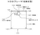
また、筐体120の裏面側には、図4、図5に示すように、上部に、磁歪アクチュエータ110を回動可能に収納する収納凹部122が設けられている。また、筐体120の裏面側の四隅には、後述するように、この筐体120から突出した駆動ロッド110aを所定の振動板に当接させた状態で、筐体120をその所定の振動板に吸着させるための吸盤125が取り付けられている。 Further, as shown in FIGS. 4 and 5, a
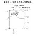
筐体120の裏面側に設けられたスライド操作部123を「ON」側とするとき、図4に示すように、磁歪アクチュエータ110は、回転軸124(図4には図示せず)を中心に回転し、駆動ロッド110aが筐体120より突出した突出状態(第1の状態)となる。図6は、この突出状態を裏面側から見た図である。 When the
駆動ロッド110aが筐体120から突出した突出状態では、図7に示すように、磁歪アクチュエータ110の駆動ロッド110aを所定の振動板130に当接させた状態を示している。この当接状態で、上述したように出力アンプ109で増幅された音声信号により磁歪アクチュエータ110が駆動されると、振動板130が音声信号に対応して振動し、この振動板130から音声信号による音声が出力される。 In the protruding state in which the driving
このように磁歪アクチュエータ110の駆動ロッド110aを所定の振動板130に当接し、この振動板130から音声出力を得る場合、ユーザは、上述したイコライザ107における周波数特性の補正内容として、この振動板130の材質に対応したものを選択できる。 In this way, when the
例えば、スライド操作部123を「ON」側とするとき、図8に示すように、筐体120の正面側に配設された表示部103に、材質、厚さの選択枝が表示される(なお、図8の表示例では材質の選択枝のみ示しているが、厚さの選択枝は例えば材質が選択された後に表示される)。この表示状態で、ユーザは、操作部102を操作して、上述の所定の振動板130の材質、あるいはその材質に近い材質を選択できる。これにより、イコライザ107における周波数特性の補正内容を、所定の振動板130の材質に対応したものとすることができ、この振動板130からの音声出力の周波数特性が、この振動板130の材質に依らずに、所定の周波数特性に近づくようにできる。 For example, when the
なお、HDD105に種々の材質の振動板にマッチした曲をオリジナルコンテンツとしてダウンロードあるいは予めプリセットしておくことで、所定の振動板130の材質にマッチした曲を容易に再生して楽しむことができる。例えば、図9は、HDD105に記憶されている「木」にマッチした曲、例えばA曲、B曲、C曲を表示部103に表示した状態を示している。ユーザは、この表示状態から操作部102を操作して所望の曲を選択して再生できる。 In addition, by downloading or presetting music matched with diaphragms of various materials to the
また、このように駆動ロッド110aが所定の振動板130に当接した状態では、筐体120の裏面側に取り付けられた吸盤125により、筐体120をこの振動板130に吸着させることができる。これにより、ユーザが筐体120を持ち続けなくても、その当接状態を保持でき、使い勝手が向上する。 Further, in this state where the
また、筐体120の裏面側に設けられたスライド操作部123を「OFF」側とするとき、図5に示すように、磁歪アクチュエータ110は、回転軸124(図5には図示せず)を中心に回転し、駆動ロッド110aが収納凹部122に収納された収納状態(第2の状態)となる。図10は、この収納状態を裏面側から見た図である。 Further, when the
駆動ロッド110aが収納凹部122に収納された収納状態では、図10、図11に示すように、磁歪アクチュエータ110の駆動ロッド110aが振動板121に当接した状態となる。この当接状態で、上述したように出力アンプ109で増幅された音声信号により磁歪アクチュエータ110が駆動されると、振動板121が音声信号に対応して振動し、この振動板121から音声信号による音声が出力される。なおこの場合、イコライザ107における周波数特性の補正内容は、この振動板121に対応した補正内容に自動的に設定される。 In the storage state where the
なお、アクチュエータ出力状態またはヘッドホン出力状態のいずれかを選択する際、図12に示すように、筐体120の正面側に配設された表示部103に、アクチュエータおよびヘッドホンの選択枝が表示される。この表示状態で、ユーザは、操作部102を操作して、アクチュエータ出力状態またはヘッドホン出力状態のいずれかを選択できる。 When selecting either the actuator output state or the headphone output state, as shown in FIG. 12, the selection of actuator and headphone is displayed on the
上述したHDDプレーヤ100によれば、駆動ロッド110aを筐体120から突出させた突出状態とし、この駆動ロッド110aが当接する所定の振動板130を大きいものとすることで、充分な音量を得ることができ、しかも充分な音量を得るために大きな振動板を備えるものではなく携帯性を保つことができる。 According to the
また、このHDDプレーヤ100においては、駆動ロッド110aを所定の振動板130に当接させて音声出力を得るときだけ、当該駆動ロッド110aを筐体120から突出した状態とでき、その他のときは駆動ロッド110aが収納凹部122に収納された状態とできるので、駆動ロッド110aの突出が邪魔になることを回避できる。 In the
上述したHDDプレーヤ100は、説明を簡単にするため、筐体120に磁歪アクチュエータ110が1個のみ配設されたモノラル方式のものを示した。しかし、筐体120に磁歪アクチュエータ110が2個配設されたステレオ方式のHDDプレーヤ100′も同様に構成できる。図13、図14は、筐体120に磁歪アクチュエータ110が2個配設されたHDDプレーヤ100′において、駆動ロッド110aが突出された突出状態を示している。 The
また、上述したHDDプレーヤ100は、アクチュエータ出力状態とヘッドホン出力状態とを切り換えて使用するものを示したが、これら2つの出力状態を併用し得る構成とすることもできる。 Further, although the
図15は、アクチュエータ出力状態とヘッドホン出力状態とを併用し得る、第2の実施の形態としてのHDDプレーヤ100Bの構成を示している。この図15において、図1と対応する部分には同一符号を付し、その詳細説明は省略する。 FIG. 15 shows a configuration of an
このHDDプレーヤ100Bは、磁歪アクチュエータ110の駆動信号を得るための、イコライザ107A、D/Aコンバータ108Aおよび出力アンプ109Aを有している。これらイコライザ107A、D/Aコンバータ108Aおよび出力アンプ109Aは、図1に示すHDDプレーヤ100におけるイコライザ107、D/Aコンバータ108および出力アンプ109にそれぞれ対応している。 The
この場合、イコライザ107Aにおける周波数特性の補正内容は、駆動ロッド110aが筐体120より突出した突出状態(第1の状態)が選択されている場合には、複数の材質、厚さに対応した補正内容からユーザのよって選択された所定の補正内容とされる。また、このイコライザ107Aにおける周波数特性の補正内容は、駆動ロッド110aが収納凹部122に収納された収納状態(第2の状態)が選択されている場合には、自動的に筐体120の上部に取り付けられた振動板121(図3〜図5参照)に対応した補正内容とされる。 In this case, the correction contents of the frequency characteristics in the
また、このHDDプレーヤ100Bは、ヘッドホン出力を得るための、イコライザ107H、D/Aコンバータ108Hおよび出力アンプ109Hを有している。これらイコライザ107H、D/Aコンバータ108Hおよび出力アンプ109Hは、図1に示すHDDプレーヤ100におけるイコライザ107、D/Aコンバータ108および出力アンプ109にそれぞれ対応している。この場合、イコライザ107Hにおける周波数特性の補正内容は、ヘッドホンに対応した補正内容とされている。 Further, the
このHDDプレーヤ100Bのその他は、図1に示すHDDプレーヤ100と同様に構成される。 The rest of the
このHDDプレーヤ100Bでは、デコーダ106から出力される音声データは、イコライザ107A、D/Aコンバータ108Aおよび出力アンプ109Aを介して、磁歪アクチュエータ110に駆動信号として供給される。また、このHDDプレーヤ100Bでは、デコーダ106から出力される音声データは、イコライザ107H、D/Aコンバータ108Hおよび出力アンプ109Hを介して、ヘッドホンジャック117にヘッドホン用の音声信号として出力される。 In the
このように、図15に示すHDDプレーヤ100Bでは、アクチュエータ出力状態とヘッドホン出力状態とを併用できる。従って、ヘッドホンジャック117にヘッドホンを接続し、このヘッドホンで音声出力を得ている状態で、さらに磁歪アクチュエータ110を駆動して振動板を振動させ、この振動板から音声出力を得ることができる。 Thus, in the
次に、この発明の第3の実施の形態について説明する。図16は、第3の実施の形態としてのHDDプレーヤ100Aの本体部の回路構成を示している。この図16において、図1と対応する部分には同一符号を付し、適宜、その詳細説明を省略する。 Next explained is the third embodiment of the invention. FIG. 16 shows a circuit configuration of the main body of the
このHDDプレーヤ100Aは、本体部の動作を制御するコントロール回路101を有している。このコントロール回路101には、ユーザインタフェースとしての、操作部102および表示部103が接続されている。 The
また、このHDDプレーヤ100Aは、プレーヤ全体の動作を制御するコントロール回路101と、周辺機器インタフェース104と、HDD105と、デコーダ106と、イコライザ107とを有している。これらは、図1のHDDプレーヤ100におけるものと同様のものである。コントロール回路101には、ユーザインタフェースとしての、操作部102および表示部103が接続されている。 The
また、HDDプレーヤ100Aは、切換スイッチ111と、データインタフェース(I/F)112と、ベースバンド処理部113と、無線部114と、送信アンテナ115とを有している。ここで、ベースバンド処理部113、無線部114および送信アンテナ115は、無線送信部を構成している。 The
切換スイッチ111は、イコライザ107で周波数特性が補正された音声データを、データインタフェース(I/F)112またはベースバンド処理部113に選択的に供給する。後述する磁歪アクチュエータ部を本体部に接続して使用する場合、切換スイッチ111はコントロール回路101の制御のもとa側に接続され、イコライザ107の出力音声データは切換スイッチ111のa側を介してデータインタフェース112に供給される。一方、磁歪アクチュエータ部を本体部から分離して使用する場合、切換スイッチ111はコントロール回路101の制御のもとb側に接続され、イコライザ107の出力音声データは切換スイッチ111のb側を介してベースバンド処理部113に供給される。 The
データインタフェース112は、後述する磁歪アクチュエータ部を本体部に接続して使用する場合、その磁歪アクチュエータ部のデータインタフェースを接続するための端子部である。ベースバンド処理部113は、音声データに対して例えばBluetooth通信用の変調処理を行うと共に、その変調信号に対してデジタル信号からアナログ信号に変換してベースバンド信号を得る。無線部114は、ベースバンド処理部113の出力アナログ信号を無線通信周波数である2.5GHz帯の信号に変換して送信アンテナ115に供給する。送信アンテナ115は、無線部114から送られてくる2.5GHz帯の信号を無線信号として送信する。 The data interface 112 is a terminal unit for connecting a data interface of the magnetostrictive actuator unit when a magnetostrictive actuator unit to be described later is connected to the main body unit. The
なお、ベースバンド処理部113および無線部114は、コントロール回路101の制御のもと、磁歪アクチュエータ部を本体部から分離して使用する場合に、動作状態とされる。 Note that the
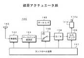
図17は、図16に示すHDDプレーヤ100Aの本体部に接続して、あるいはこの本体部から分離して使用する磁歪アクチュエータ部140の構成を示している。この図17において、図1と対応する部分には同一符号を付し、適宜その詳細説明を省略する。 FIG. 17 shows a configuration of a
この磁歪アクチュエータ部140は、全体の動作を制御するコントロール回路141を有している。また、この磁歪アクチュエータ部140は、受信アンテナ142と、無線部143と、ベースバンド処理部144とを有している。ここで、受信アンテナ142、無線部143およびベースバンド処理部144は、無線受信部を構成している。 The
受信アンテナ142は、Bluetooth通信における2.5GHz帯の無線信号を受信する。無線部143は、受信アンテナ142の受信信号に周波数変換の処理を行ってベースバンド信号を得る。ベースバンド処理部144は、無線部143で得られるベースバンド信号に対してアナログ信号からデジタル信号に変換する処理を行うと共に、そのデジタル信号に対して復調処理を行って音声データを得る。 The receiving
また、磁歪アクチュエータ部140は、切換スイッチ145と、データインタフェース(I/F)146と、D/Aコンバータ108と、出力アンプ109と、磁歪アクチュエータ110とを有している。 The
データインタフェース146は、磁歪アクチュエータ部140を上述のHDDプレーヤ100Aの本体部に接続して使用する場合、その本体部のデータインタフェース112に接続される端子部である。切換スイッチ145は、データインタフェース112に供給された音声データ、あるいはベースバンド処理部144で得られた音声データをD/Aコンバータ108に選択的に供給する。 The data interface 146 is a terminal portion connected to the data interface 112 of the main body portion when the
磁歪アクチュエータ部140を本体部に接続して使用する場合、切換スイッチ145はコントロール回路141の制御のもとc側に接続され、データインタフェース146に供給された音声データは切換スイッチ145のc側を介してD/Aコンバータ108に供給される。一方、磁歪アクチュエータ部140を本体部から分離して無線使用する場合、切換スイッチ145はコントロール回路141の制御のもとd側に接続され、ベースバンド処理部144で得られた音声データは切換スイッチ145のd側を介してD/Aコンバータ108に供給される。 When the
D/Aコンバータ108、出力アンプ109および磁歪アクチュエータ110は、図1のHDDプレーヤ100におけるものと同様のものである。 The D /
上述したように、HDDプレーヤ100Aにおいては、磁歪アクチュエータ部140を本体部に接続して使用し、あるいはこの磁歪アクチュエータ部140を本体部から分離して使用できる。ユーザは、磁歪アクチュエータ部140の接続使用あるいは無線使用のいずれかを任意に選択できる。この場合、図18に示すように、ユーザは、操作部102を操作して、HDDプレーヤ100Aの筐体120の正面側に配設された表示部103に選択画面が表示されるようにし、その後「ON」(無線使用)または「OFF」(接続使用)を選択する。なお、図18において、120aは送信アンテナ115(図16参照)が配置されている部位を示している。 As described above, in the
磁歪アクチュエータ部140の接続使用が行われる場合、磁歪アクチュエータ部140は、図19に示すように、筐体120の収納凹部122に収納された状態とされる。磁歪アクチュエータ部140は、磁歪アクチュエータ110に無線受信部等を含む回路基板部140aが接続された構成となっている。このように磁歪アクチュエータ部140が筐体120の収納凹部122に収納された状態では、図示せずも、本体部のデータインタフェース112(図16参照)が磁歪アクチュエータ部140のデータインタフェース146(図17参照)に接続された状態となる。 When the
この磁歪アクチュエータ部140は、上述したHDDプレーヤ100における磁歪アクチュエータ110と同様に、駆動ロッド110aの突出状態(第1の状態)または駆動ロッド110aの収納状態(第2の状態)で使用可能となる。 This
すなわち、筐体120の裏面側に設けられたスライド操作部123を「ON」側とするとき、図19、図20に実線で示すように、磁歪アクチュエータ部140は、回転軸124を中心に回転し、駆動ロッド110aが筐体120より突出した状態となる。一方、スライド操作部123を「OFF」側とするとき、図19、図20に破線で示すように、磁歪アクチュエータ部140は、回転軸124を中心に回転し、駆動ロッド110aが収納凹部122に収納され、振動板121に当接した状態となる。 That is, when the
なお、図19、図20において、図6、図7、図10、図11と対応する部分には同一符号を付して示し、適宜説明を省略している。 19 and 20, parts corresponding to those in FIGS. 6, 7, 10, and 11 are given the same reference numerals, and description thereof is omitted as appropriate.
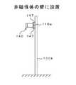
磁歪アクチュエータ部140の無線使用が行われる場合、磁歪アクチュエータ部140は、図19に破線で示すように、筐体120の収納凹部122から取り出された状態とされる。そして、磁歪アクチュエータ部140は、磁歪アクチュエータ110の駆動ロッド110aが所定の振動板に当接した状態で、当該所定の振動板上に設置されて使用される。 When the
図21は、磁歪アクチュエータ部140が所定の振動板としての磁性体の壁130a上に設置された例を示している。この場合、磁歪アクチュエータ110を構成する永久磁石162(図2参照)の磁力によって、磁歪アクチュエータ部140は磁性体の壁130a上に設置された状態が保持される。 FIG. 21 shows an example in which the
また、図22は、磁歪アクチュエータ部140が所定の振動板としての非磁性体の壁130b上に設置された例を示し、図23は、磁歪アクチュエータ部140が所定の振動板としての机の上板(非磁性体)130cの下面に設置された例を示している。このように磁歪アクチュエータ部140を非磁性体の壁130bまたは机の上板(非磁性体)130cに設置する場合、例えば吸盤147によって、磁歪アクチュエータ部140は壁130bまたは机の上板130cに設置された状態が保持される。 FIG. 22 shows an example in which the
図24A,Bは、吸盤付きの磁歪アクチュエータ部140の構成を示している。図24Aは側面側から見た図であり、図24Bは駆動ロッド110aの突出側から見た図である。この場合、磁歪アクチュエータ110の駆動ロッド110a側に、駆動ロッド110aが貫通される丸穴149を中央に持つ例えば正方形の吸盤取り付け板148が固定され、この吸盤取り付け板148の四隅に吸盤147が取り付けられている。このように磁歪アクチュエータ部140を吸盤147によって所定の振動板に吸着させることで、ユーザは磁歪アクチュエータ部140をその駆動ロッド110aが振動板に当接した状態で持ち続けなくても、その当接状態を保持でき、使い勝手が向上する。 24A and 24B show the configuration of the
図16に示すHDDプレーヤ100Aの本体部および図17に示す磁歪アクチュエータ部140の再生時における動作を説明する。 An operation during reproduction of the main body of the
最初に、磁歪アクチュエータ部140を本体部に接続して使用する「接続使用」の動作を説明する。この場合、本体部では、切換スイッチ111はa側に接続され、ベースバンド処理部113および無線部114は非動作状態とされ、磁歪アクチュエータ部140では、切換スイッチ145はc側に接続され、無線部143およびベースバンド処理部144は非動作状態とされる。 First, the operation of “connection use” in which the
HDD105から圧縮音声データが読み出され、この圧縮音声データはデコーダ106に供給される。デコーダ106では、圧縮音声データに対して伸長処理が施される。このデコーダ106から出力される音声データはイコライザ107に供給される。イコライザ107では、音声データ対して周波数特性の補正処理が施される。 The compressed audio data is read from the
イコライザ107で周波数特性が補正された音声データは、切換スイッチ145のa側およびデータインタフェース112を介して磁歪アクチュエータ140のデータインタフェース146に供給される。 The audio data whose frequency characteristics have been corrected by the
そして、データインタフェース146に供給された音声データは、切換スイッチ145のc側を介してD/Aコンバータ108に供給され、デジタル信号からアナログ信号に変換される。D/Aコンバータ108から出力されるアナログの音声信号は、出力アンプ109で増幅され、その後に磁歪アクチュエータ110に駆動信号として供給される。 The audio data supplied to the
これにより、駆動ロッド110aの突出状態(第1の状態)では、この駆動ロッド110aが当接される所定の振動板が振動し、この所定の振動板から音声出力が得られる。また、駆動ロッド110aの収納状態(第2の状態)では、この駆動ロッド110aが当接される、筐体120に取り付けられた振動板121が振動し、この振動板121から音声出力が得られる。 Thereby, in the projecting state (first state) of the
次に、磁歪アクチュエータ部140を本体部から分離して使用する「無線使用」の動作を説明する。この場合、本体部では、切換スイッチ111はb側に接続され、ベースバンド処理部113および無線部114は動作状態とされ、磁歪アクチュエータ部140では、切換スイッチ145はd側に接続され、無線部143およびベースバンド処理部144は動作状態とされる。 Next, the “wireless use” operation in which the
HDD105から圧縮音声データが読み出され、この圧縮音声データはデコーダ106に供給される。デコーダ106では、圧縮音声データに対して伸長処理が施される。このデコーダ106から出力される音声データはイコライザ107に供給される。イコライザ107では、音声データ対して周波数特性の補正処理が施される。 The compressed audio data is read from the
イコライザ107で周波数特性が補正された音声データは、切換スイッチ145のa側を介してベースバンド処理部113に供給される。ベースバンド処理部113では音声データが変調され、さらにアナログ信号に変換され、ベースバンド信号が得られる。そして、このベースバンド信号は無線部で2.5GHz帯の信号に変換され、この信号は送信アンテナ115から無線信号として送信される。 The audio data whose frequency characteristics have been corrected by the
このように本体部の送信アンテナ115から送信される無線信号は、磁歪アクチュエータ部140の受信アンテナ142で受信される。この受信アンテナ142の受信信号は無線部143に供給され、周波数変換されてベースバンド信号とされる。このベースバンド信号はベースバンド処理部144に供給される。ベースバンド処理部144では、ベースバンド信号に対して、アナログ信号をデジタル信号に変換する処理、さらには復調処理が行われて音声データが得られる。 Thus, the radio signal transmitted from the
この音声データは、切換スイッチ145のd側を介してD/Aコンバータ108に供給され、デジタル信号からアナログ信号に変換される。D/Aコンバータ108から出力されるアナログの音声信号は、出力アンプ109で増幅され、その後に磁歪アクチュエータ110に駆動信号として供給される。これにより、磁歪アクチュエータ部140の駆動ロッド110が当接される所定の振動板が振動し、この所定の振動板から音声出力が得られる。 This audio data is supplied to the D /
上述したHDDプレーヤ100Aによれば、図1に示すHDDプレーヤ100と同様に、駆動ロッド110aを筐体120から突出させた突出状態とし、この駆動ロッド110aが当接する所定の振動板130を大きいものとすることで、充分な音量を得ることができ、しかも充分な音量を得るために大きな振動板を備えるものではなく携帯性を保つことができる。 According to the
また、このHDDプレーヤ100Aによれば、磁歪アクチュエータ部140を本体部から取り外すことができ、その場合、本体部から磁歪アクチュエータ部140に音声データが無線送信され、磁歪アクチュエータ部140の磁歪アクチュエータ110はその音声データで駆動できるものであり、HDDプレーヤ100Aの全体ではなく、磁歪アクチュエータ部140のみを所定の振動板に設置すればよく、取扱が容易となる利益がある。 Further, according to the
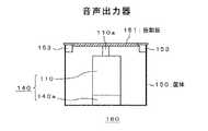
なお、上述では、磁歪アクチュエータ部140の駆動ロッド110aを所定の振動板に当接するものを示したが、図25に示すように、一面に変位伝達部としての振動板151が設けられた箱状の小筐体150に、当該磁歪アクチュエータ部140をその駆動ロッド110aが振動板151に当接するように収納し、音声出力器160として使用することも考えられる。筐体150の振動板151側には、この音声出力器160を壁などに取り付けるための吸盤153が設けられている。 In the above description, the
図26は、上述した音声出力器160を部屋170の壁171に配設し、振動板151と共に壁171をも振動板として使用する、マルチチャネルスピーカシステムの使用例を示している。また、図27は、上述した音声出力器160を、ベッド180のボード181に配設し、振動板151と共にボード181をも振動板として使用する使用例を示している。 FIG. 26 shows an example of use of a multi-channel speaker system in which the above-described
また、上述では、磁歪アクチュエータ部140の駆動ロッド110aを所定の振動板に当接するものを示したが、図28A,Bに示すように、磁歪アクチュエータ部140を、その駆動ロッド110aの変位を拡大する変位拡大器190に取り付けて使用することも考えられる。図28Aは正面図、図28Bは側面図である。 In the above description, the driving
変位拡大器190は、例えばバネ材料、例えばりんせい銅が使用されて形成されている。この場合、駆動ロッド110aのΔdの変位は、変位拡大器190の駆動ロッド110aの軸方向と直交する方向の部分(変位伝達部190a)にp(>1)倍の変位となってに現れる。回路基板部140aには、このように変位拡大器190に取り付けられた磁歪アクチュエータ部140を壁などに取り付けるための吸盤191が配設されている。 The
また、上述では、磁歪アクチュエータ部140の駆動ロッド110aの変位を伝達する変位伝達部(駆動ロッド110a自体、小筐体150に設けられた振動板151、変位拡大器190の変位伝達部)が、振動板としての壁などに当接させる例を示したが、この変位伝達部を人間の一部に当接させて、骨伝導によって音声出力を得るようにもできる。 Further, in the above description, the displacement transmission unit (the
例えば、図29Bに示すようにネックバンド193に磁歪アクチュエータ部140を取り付け、駆動ロッド110aを、図29Aに示すように、例えば耳194の後に当接させた状態とする。この場合、駆動ロッド110aの変位によって、頭蓋骨が振動し、骨伝導による音声出力が得られる。 For example, the
なお、上述では、筐体120の収納凹部122には、磁歪アクチュエータ110が、小筐体150に収納されてもおらず、変位拡大器190に取り付けられてもいない、いわゆるむき出し状態で収納される。しかし、この磁歪アクチュエータ110を、小筐体150に収納された状態(図25参照)、あるいは変位拡大器190に取り付けられた状態(図28参照)で、筐体120の収納凹部122に収納することもできる。ここで、磁歪アクチュエータ110がむき出しの状態にある場合、駆動ロッド110aの変位を伝達する変位伝達部は駆動ロッド110aそのものである。また、磁歪アクチュエータ110が小筐体150に収納されている場合、変位伝達部は振動板151で構成される一の面である。また、磁歪アクチュエータ110が変位拡大器190に取り付けられている場合、変位伝達部は変位拡大器190の駆動ロッド110aの軸方向と直交する方向の部分となる。 In the above description, the
次に、この発明の第4の実施の形態について説明する。図30は、第4の実施の形態としての携帯電話機200の構成を示している。 Next explained is the fourth embodiment of the invention. FIG. 30 shows the configuration of a
この携帯電話機200は、マイクロコンピュータを有して構成され、電話機全体の動作を制御する制御部201を有している。この制御部201には、ユーザが種々の操作を行うためのキー操作部202、送受信状態、操作状態等を表示する、液晶表示素子等からなる表示部203、および多数の相手先の電話番号などを格納した電話長メモリ等として使用されるメモリ204が接続されている。 The
また、携帯電話機200は、送受信アンテナ205と、無線部206と、ベースバンド処理部207と、音声処理部208とを有している。無線部206は、周波数変換、復調/変調の処理を行う。ベースバンド処理部207は、音声情報、データ情報等の分離/合成の処理を行う。音声処理部208は、音声信号の復号化/符号化の処理を行う。 In addition, the
この音声処理部208には、磁歪アクチュエータ110およびマイクロホン210が接続されている。なお、この磁歪アクチュエータ110は、図1に示すHDDプレーヤ100を構成する磁歪アクチュエータ110と同様のものとされる(図2A,B参照)。 The
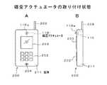
図31A,Bは、携帯電話機200における磁歪アクチュエータ110の取り付け状態を示している。この場合、磁歪アクチュエータ110は、駆動ロッド110aが筐体211から突出した状態で配設される。 31A and 31B show how the
図30に示す携帯電話機200の動作を簡単に説明する。まず、受信時の動作を説明する。送受信アンテナ205で受信された携帯電話信号(高周波信号)は無線部206に供給される。この無線部206では、携帯電話信号がミキサにより中間周波信号に変換され、さらにその中間周波信号からベースバンド信号が復調される。そして、このベースバンド信号はベースバンド処理部207に供給される。 The operation of the
このベースバンド処理部207では、ベースバンド信号から音声情報、データ情報(画像情報、テキスト情報を含む)等が分離される。そして、音声情報は音声処理部208に供給され、データ情報は制御部201に供給される。制御部201は、データ情報に基づいた制御動作を行うと共に、必要に応じて、表示部203に画像、文字等を表示する。 The
音声処理部208では、音声情報に対して復号化処理が行われ、音声信号が得られる。そして、この音声処理部208から磁歪アクチュエータ110に音声信号に対応したドライブ信号Sdが供給される。この場合、図32に示すように、ユーザは、磁歪アクチュエータ110の駆動ロッド110aを耳の前や後等に接触させることで、頭蓋骨が振動し、音声信号による受話音声(骨導音)を聞くことができる。 The
なお、磁歪アクチュエータ110の駆動ロッド110aを所定の振動板に当接させた状態とすることで、この所定の振動板が振動し、この振動板から音声信号による受話音声を出力させることができる。 In addition, by setting the driving
次に、送信時の動作を説明する。マイクロホン110からの音声信号は音声処理部208に供給される。音声処理部208では、この音声信号に対して符号化処理が行われ、音声情報が得られる。この音声情報はベースバンド処理部207に供給される。 Next, the operation during transmission will be described. An audio signal from the
ベースバンド処理部207では、音声情報と、制御部201から供給されるデータ情報とが合成され、送信すべきベースバンド信号が生成される。このベースバンド信号は無線部206に供給される。 In the
無線部206では、ベースバンド信号に対して変調処理が行われて中間周波信号が得られ、さらにこの中間周波信号がミキサにより携帯電話信号(高周波信号)に変換される。この携帯電話信号は送受信アンテナ205に供給されて送信される。
上述した携帯電話機200によれば、磁歪アクチュエータ110の駆動ロッド110aを筐体211から突出した状態としているので、例えばこの駆動ロッド110aを耳の前や後等に接触させて、骨伝導による受話音声(骨導音)を容易に得ることができ、あるいはこの駆動ロッド110aを所定の振動板に当接させ、その所定の振動板から受話音声を容易に得ることができる。 According to the
この発明は、携帯性を保ちながら、充分な音量を得ることができるものであり、HDDプレーヤ、携帯電話機などに適用できる。 The present invention can obtain a sufficient volume while maintaining portability, and can be applied to an HDD player, a mobile phone, and the like.
100,100′,100A,100B・・・HDDプレーヤ、101・・・コントロール回路、102・・・操作部、103・・・表示部、104・・・周辺機器I/F、105・・・HDD、106・・・デコーダ、107,107A,107H・・・イコライザ、108,108A,108H・・・D/Aコンバータ、109,109A,109H・・・出力アンプ、110・・・磁歪アクチュエータ、110a・・・駆動ロッド、111・・・切換スイッチ、112・・・データインタフェース、113・・・ベースバンド処理部、114・・・無線部、115・・・送信アンテナ、116・・・切換スイッチ、117・・・ヘッドホンジャック、120・・・筐体、121・・・振動板、122・・・収納凹部、123・・・スライド操作部、124・・・回転軸、125・・・吸盤、130・・・所定の振動板、140・・・磁歪アクチュエータ部、140a・・・回路基板部、141・・・コントロール回路、142・・・受信アンテナ、143・・・無線部、144・・・ベースバンド処理部、145・・・切換スイッチ、146・・・データインタフェース、147・・・吸盤、148・・・吸盤取付板、150・・・小筐体、151・・・振動板、153・・・吸盤、170・・・部屋、171・・・壁、180・・・ベッド、181・・・ボード、190・・・変位拡大器、190a・・・変位伝達部、191・・・吸盤、193・・・ネックバンド、200・・・携帯電話機、201・・・制御部、202・・・キー操作部、203・・・表示部、204・・・メモリ、205・・・送受信アンテナ、206・・・無線部、207・・・ベースバンド処理部、208・・・音声処理部、210・・・マイクロホン
DESCRIPTION OF
Claims (8)
Translated fromJapanese上記音声信号出力部から出力される音声信号に基づいて駆動される磁歪アクチュエータとを備え、
上記磁歪アクチュエータは、駆動ロッドの変位を伝達する変位伝達部が筐体より突出した状態で、あるいは該変位伝達部が筐体より突出可能に配設されている
ことを特徴とする携帯音声駆動装置。An audio signal output unit for outputting an audio signal;
A magnetostrictive actuator driven based on the audio signal output from the audio signal output unit,
The magnetostrictive actuator is characterized in that a displacement transmission part for transmitting displacement of a drive rod protrudes from the casing, or the displacement transmission part is arranged to protrude from the casing. .
ことを特徴とする請求項1に記載の携帯音声駆動装置。2. The magnetostrictive actuator is housed in a small housing having one surface made of a diaphragm in a state where the drive rod is in contact with the one surface. Portable voice drive device.
ことを特徴とする請求項1に記載の携帯音声駆動装置。The portable audio drive device according to claim 1, wherein the magnetostrictive actuator is attached to a displacement expander that expands the displacement of the drive rod.
ことを特徴とする請求項1に記載の携帯音声駆動装置。The portable audio drive device according to claim 1, wherein the housing includes a suction cup for adsorbing to the predetermined vibration plate in a state where the displacement transmission unit is in contact with the predetermined vibration plate.
上記イコライザ部の補正内容をユーザが複数の補正内容から選択する補正内容選択部とをさらに備える
ことを特徴とする請求項1に記載の携帯音声駆動装置。An equalizer that is inserted between the audio signal output unit and the magnetostrictive actuator and corrects the frequency characteristics of the audio signal;
The portable audio drive device according to claim 1, further comprising: a correction content selection unit that allows a user to select a correction content of the equalizer unit from a plurality of correction content.
上記磁歪アクチュエータの配設状態を、上記変位伝達部が上記筐体より突出した第1の状態、および上記変位伝達部が上記振動板に当接した第2の状態に切り換える切り換え機構をさらに備える
ことを特徴とする請求項1に記載の携帯音声駆動装置。Further comprising a diaphragm attached to the housing,
And a switching mechanism for switching the arrangement state of the magnetostrictive actuator between a first state in which the displacement transmission unit protrudes from the housing and a second state in which the displacement transmission unit is in contact with the diaphragm. The portable audio drive device according to claim 1.
上記磁歪アクチュエータが上記筐体から取り外されるとき、上記音声信号出力部から出力される音声信号を無線送信する無線送信部と、
上記磁歪アクチュエータに一体的に固定され、上記磁歪アクチュエータが上記筐体から取り外されるとき、上記無線送信部から送られてくる音声信号を受信する無線受信部とをさらに備える
ことを特徴とする請求項1に記載の携帯音声駆動装置。The magnetostrictive actuator is detachably disposed on the housing,
When the magnetostrictive actuator is removed from the housing, a wireless transmission unit that wirelessly transmits an audio signal output from the audio signal output unit; and
The wireless receiving unit, which is integrally fixed to the magnetostrictive actuator and receives an audio signal transmitted from the wireless transmitting unit when the magnetostrictive actuator is removed from the housing. 2. The portable audio drive device according to 1.
ことを特徴とする請求項7に記載の携帯音声駆動装置。
The portable audio drive device according to claim 7, wherein the magnetostrictive actuator includes a suction cup for adsorbing the displacement transmitting portion in contact with the predetermined vibration plate.
Priority Applications (6)
| Application Number | Priority Date | Filing Date | Title |
|---|---|---|---|
| JP2005295636AJP2007104603A (en) | 2005-10-07 | 2005-10-07 | Portable sound driver |
| US11/528,466US20070081679A1 (en) | 2005-10-07 | 2006-09-28 | Portable audio drive unit |
| CNA2006101627114ACN1960577A (en) | 2005-10-07 | 2006-09-29 | Portable audio drive unit |
| KR20060097012AKR20070039403A (en) | 2005-10-07 | 2006-10-02 | Portable voice drive |
| EP20060021100EP1773096A2 (en) | 2005-10-07 | 2006-10-06 | Portable audio drive unit |
| BRPI0604240-6ABRPI0604240A (en) | 2005-10-07 | 2006-10-06 | portable audio drive unit |
Applications Claiming Priority (1)
| Application Number | Priority Date | Filing Date | Title |
|---|---|---|---|
| JP2005295636AJP2007104603A (en) | 2005-10-07 | 2005-10-07 | Portable sound driver |
Publications (2)
| Publication Number | Publication Date |
|---|---|
| JP2007104603Atrue JP2007104603A (en) | 2007-04-19 |
| JP2007104603A5 JP2007104603A5 (en) | 2008-10-23 |
Family
ID=37308843
Family Applications (1)
| Application Number | Title | Priority Date | Filing Date |
|---|---|---|---|
| JP2005295636AAbandonedJP2007104603A (en) | 2005-10-07 | 2005-10-07 | Portable sound driver |
Country Status (6)
| Country | Link |
|---|---|
| US (1) | US20070081679A1 (en) |
| EP (1) | EP1773096A2 (en) |
| JP (1) | JP2007104603A (en) |
| KR (1) | KR20070039403A (en) |
| CN (1) | CN1960577A (en) |
| BR (1) | BRPI0604240A (en) |
Cited By (23)
| Publication number | Priority date | Publication date | Assignee | Title |
|---|---|---|---|---|
| JP5296911B1 (en)* | 2012-09-25 | 2013-09-25 | 丸山 徹 | Vibration generation system |
| JP5296912B1 (en)* | 2012-09-25 | 2013-09-25 | 丸山 徹 | Vibration generation system |
| JP5311523B1 (en)* | 2012-09-25 | 2013-10-09 | 丸山 徹 | Speaker system |
| JP2014003400A (en)* | 2012-06-15 | 2014-01-09 | Yuji Hosoi | Mobile phone |
| JP2015122653A (en)* | 2013-12-24 | 2015-07-02 | 京セラ株式会社 | Sound generator |
| US9479624B2 (en) | 2012-01-20 | 2016-10-25 | Rohm Co., Ltd. | Mobile telephone |
| US9485559B2 (en) | 2011-02-25 | 2016-11-01 | Rohm Co., Ltd. | Hearing system and finger ring for the hearing system |
| US9705548B2 (en) | 2013-10-24 | 2017-07-11 | Rohm Co., Ltd. | Wristband-type handset and wristband-type alerting device |
| US9716782B2 (en) | 2010-12-27 | 2017-07-25 | Rohm Co., Ltd. | Mobile telephone |
| US9729971B2 (en) | 2012-06-29 | 2017-08-08 | Rohm Co., Ltd. | Stereo earphone |
| US9742887B2 (en) | 2013-08-23 | 2017-08-22 | Rohm Co., Ltd. | Mobile telephone |
| CN107493540A (en)* | 2017-10-10 | 2017-12-19 | 温州大学瓯江学院 | A kind of portable blue-tooth audio amplifier |
| US9894430B2 (en) | 2010-12-27 | 2018-02-13 | Rohm Co., Ltd. | Incoming/outgoing-talk unit and incoming-talk unit |
| US10013862B2 (en) | 2014-08-20 | 2018-07-03 | Rohm Co., Ltd. | Watching system, watching detection device, and watching notification device |
| WO2018216525A1 (en)* | 2017-05-24 | 2018-11-29 | パイオニア株式会社 | Vibration transmission device and vibration transmission method |
| US10356231B2 (en) | 2014-12-18 | 2019-07-16 | Finewell Co., Ltd. | Cartilage conduction hearing device using an electromagnetic vibration unit, and electromagnetic vibration unit |
| JP2020065126A (en)* | 2018-10-16 | 2020-04-23 | アルパイン株式会社 | Sound generation device |
| CN111479185A (en)* | 2020-02-24 | 2020-07-31 | 李娜 | Automatic adsorption mechanism driving system for protecting eardrum |
| US10778824B2 (en) | 2016-01-19 | 2020-09-15 | Finewell Co., Ltd. | Pen-type handset |
| US10795321B2 (en) | 2015-09-16 | 2020-10-06 | Finewell Co., Ltd. | Wrist watch with hearing function |
| US10967521B2 (en) | 2015-07-15 | 2021-04-06 | Finewell Co., Ltd. | Robot and robot system |
| US11526033B2 (en) | 2018-09-28 | 2022-12-13 | Finewell Co., Ltd. | Hearing device |
| JP2023060993A (en)* | 2021-10-19 | 2023-05-01 | 茂樹 小林 | Three-dimensional self-sounding canonical complex spatial audio system that reproduces self-sounding sound according to its physical essence |
Families Citing this family (7)
| Publication number | Priority date | Publication date | Assignee | Title |
|---|---|---|---|---|
| WO2010110556A2 (en)* | 2009-03-24 | 2010-09-30 | 지디텍 주식회사 | Bone conduction speaker |
| WO2010113038A2 (en)* | 2009-04-01 | 2010-10-07 | Robert Katz | Improved inertial type acoustic transducer and subsystems |
| GB0921195D0 (en)* | 2009-12-03 | 2010-01-20 | Feonic Plc | Audio device |
| DE102010010801B4 (en)* | 2010-03-09 | 2013-02-21 | Eto Magnetic Gmbh | actuator |
| US8823221B1 (en)* | 2012-09-26 | 2014-09-02 | The United States Of America As Represented By The Secretary Of The Navy | Optimized galfenol-type magnetostrictive actuator |
| US10863264B2 (en)* | 2017-01-23 | 2020-12-08 | David Sampson | Vibration inducing tactile apparatus |
| CN111509814B (en)* | 2020-05-29 | 2021-10-12 | 维沃移动通信有限公司 | Data cables and charging equipment |
- 2005
- 2005-10-07JPJP2005295636Apatent/JP2007104603A/ennot_activeAbandoned
- 2006
- 2006-09-28USUS11/528,466patent/US20070081679A1/ennot_activeAbandoned
- 2006-09-29CNCNA2006101627114Apatent/CN1960577A/enactivePending
- 2006-10-02KRKR20060097012Apatent/KR20070039403A/ennot_activeWithdrawn
- 2006-10-06BRBRPI0604240-6Apatent/BRPI0604240A/ennot_activeIP Right Cessation
- 2006-10-06EPEP20060021100patent/EP1773096A2/ennot_activeWithdrawn
Cited By (39)
| Publication number | Priority date | Publication date | Assignee | Title |
|---|---|---|---|---|
| US9894430B2 (en) | 2010-12-27 | 2018-02-13 | Rohm Co., Ltd. | Incoming/outgoing-talk unit and incoming-talk unit |
| US10779075B2 (en) | 2010-12-27 | 2020-09-15 | Finewell Co., Ltd. | Incoming/outgoing-talk unit and incoming-talk unit |
| US9716782B2 (en) | 2010-12-27 | 2017-07-25 | Rohm Co., Ltd. | Mobile telephone |
| US9485559B2 (en) | 2011-02-25 | 2016-11-01 | Rohm Co., Ltd. | Hearing system and finger ring for the hearing system |
| US9980024B2 (en) | 2011-02-25 | 2018-05-22 | Rohm Co., Ltd. | Hearing system and finger ring for the hearing system |
| US10778823B2 (en) | 2012-01-20 | 2020-09-15 | Finewell Co., Ltd. | Mobile telephone and cartilage-conduction vibration source device |
| US10158947B2 (en) | 2012-01-20 | 2018-12-18 | Rohm Co., Ltd. | Mobile telephone utilizing cartilage conduction |
| US9479624B2 (en) | 2012-01-20 | 2016-10-25 | Rohm Co., Ltd. | Mobile telephone |
| US10079925B2 (en) | 2012-01-20 | 2018-09-18 | Rohm Co., Ltd. | Mobile telephone |
| JP2014003400A (en)* | 2012-06-15 | 2014-01-09 | Yuji Hosoi | Mobile phone |
| US9729971B2 (en) | 2012-06-29 | 2017-08-08 | Rohm Co., Ltd. | Stereo earphone |
| US10506343B2 (en) | 2012-06-29 | 2019-12-10 | Finewell Co., Ltd. | Earphone having vibration conductor which conducts vibration, and stereo earphone including the same |
| US10834506B2 (en) | 2012-06-29 | 2020-11-10 | Finewell Co., Ltd. | Stereo earphone |
| JP5296911B1 (en)* | 2012-09-25 | 2013-09-25 | 丸山 徹 | Vibration generation system |
| JP5296912B1 (en)* | 2012-09-25 | 2013-09-25 | 丸山 徹 | Vibration generation system |
| JP5311523B1 (en)* | 2012-09-25 | 2013-10-09 | 丸山 徹 | Speaker system |
| US9742887B2 (en) | 2013-08-23 | 2017-08-22 | Rohm Co., Ltd. | Mobile telephone |
| US10075574B2 (en) | 2013-08-23 | 2018-09-11 | Rohm Co., Ltd. | Mobile telephone |
| US10237382B2 (en) | 2013-08-23 | 2019-03-19 | Finewell Co., Ltd. | Mobile telephone |
| US9705548B2 (en) | 2013-10-24 | 2017-07-11 | Rohm Co., Ltd. | Wristband-type handset and wristband-type alerting device |
| US10103766B2 (en) | 2013-10-24 | 2018-10-16 | Rohm Co., Ltd. | Wristband-type handset and wristband-type alerting device |
| JP2015122653A (en)* | 2013-12-24 | 2015-07-02 | 京セラ株式会社 | Sound generator |
| US10380864B2 (en) | 2014-08-20 | 2019-08-13 | Finewell Co., Ltd. | Watching system, watching detection device, and watching notification device |
| US10013862B2 (en) | 2014-08-20 | 2018-07-03 | Rohm Co., Ltd. | Watching system, watching detection device, and watching notification device |
| US10356231B2 (en) | 2014-12-18 | 2019-07-16 | Finewell Co., Ltd. | Cartilage conduction hearing device using an electromagnetic vibration unit, and electromagnetic vibration unit |
| US10848607B2 (en) | 2014-12-18 | 2020-11-24 | Finewell Co., Ltd. | Cycling hearing device and bicycle system |
| US11601538B2 (en) | 2014-12-18 | 2023-03-07 | Finewell Co., Ltd. | Headset having right- and left-ear sound output units with through-holes formed therein |
| US10967521B2 (en) | 2015-07-15 | 2021-04-06 | Finewell Co., Ltd. | Robot and robot system |
| US10795321B2 (en) | 2015-09-16 | 2020-10-06 | Finewell Co., Ltd. | Wrist watch with hearing function |
| US10778824B2 (en) | 2016-01-19 | 2020-09-15 | Finewell Co., Ltd. | Pen-type handset |
| WO2018216525A1 (en)* | 2017-05-24 | 2018-11-29 | パイオニア株式会社 | Vibration transmission device and vibration transmission method |
| CN107493540B (en)* | 2017-10-10 | 2019-06-14 | 温州大学瓯江学院 | A portable bluetooth speaker |
| CN107493540A (en)* | 2017-10-10 | 2017-12-19 | 温州大学瓯江学院 | A kind of portable blue-tooth audio amplifier |
| US11526033B2 (en) | 2018-09-28 | 2022-12-13 | Finewell Co., Ltd. | Hearing device |
| JP2020065126A (en)* | 2018-10-16 | 2020-04-23 | アルパイン株式会社 | Sound generation device |
| JP7140458B2 (en) | 2018-10-16 | 2022-09-21 | アルパイン株式会社 | sound generator |
| CN111479185A (en)* | 2020-02-24 | 2020-07-31 | 李娜 | Automatic adsorption mechanism driving system for protecting eardrum |
| CN111479185B (en)* | 2020-02-24 | 2021-08-31 | 刘春艳 | Automatic adsorption mechanism driving system for protecting eardrum |
| JP2023060993A (en)* | 2021-10-19 | 2023-05-01 | 茂樹 小林 | Three-dimensional self-sounding canonical complex spatial audio system that reproduces self-sounding sound according to its physical essence |
Also Published As
| Publication number | Publication date |
|---|---|
| EP1773096A2 (en) | 2007-04-11 |
| BRPI0604240A (en) | 2007-08-21 |
| CN1960577A (en) | 2007-05-09 |
| US20070081679A1 (en) | 2007-04-12 |
| KR20070039403A (en) | 2007-04-11 |
Similar Documents
| Publication | Publication Date | Title |
|---|---|---|
| JP2007104603A (en) | Portable sound driver | |
| TW595241B (en) | Audio system with removable, active faceplate | |
| US20130308798A1 (en) | Communication Terminal Having Bone Conduction Function | |
| US20030114133A1 (en) | MP3 player for vehicles | |
| US20150063595A1 (en) | Speaker apparatus | |
| JP2005158255A5 (en) | ||
| JP2011071691A (en) | Electronic equipment | |
| JP4317834B2 (en) | Sound output device and sound output control program | |
| KR100689576B1 (en) | Sound output device | |
| JP2011182368A (en) | Electronic device | |
| JP6784320B2 (en) | Playback system | |
| JP4148097B2 (en) | Sound playback device | |
| JP2004254315A (en) | Video playback device and video playback method for portable electronic device | |
| US6856691B2 (en) | Electronic apparatus including loudspeaker system | |
| JP2009124271A (en) | Audio apparatus and external adapter used for the audio apparatus | |
| KR100601620B1 (en) | M.P.3. (MP3) Player / Mobile Handheld Communication Wireless Terminal | |
| JP4906241B2 (en) | Audio transmission system | |
| JPH07219418A (en) | Portable voice generator and voice reproducing system utilizing it | |
| JP2003032781A (en) | Portable sound station | |
| KR20080110247A (en) | Multimedia data playback system using earphone and earphone with remote controller for multimedia data storage and its control method | |
| JP4270643B2 (en) | Audio recording / playback device | |
| JP3099755U (en) | MP3 audio recording / reproducing device | |
| KR100321917B1 (en) | Headphone for play of mp3 file | |
| JP2002078055A (en) | Portable music player | |
| JP3159971U (en) | Voice reproduction system and its loudspeaker |
Legal Events
| Date | Code | Title | Description |
|---|---|---|---|
| A521 | Written amendment | Free format text:JAPANESE INTERMEDIATE CODE: A523 Effective date:20080909 | |
| A621 | Written request for application examination | Free format text:JAPANESE INTERMEDIATE CODE: A621 Effective date:20080909 | |
| A762 | Written abandonment of application | Free format text:JAPANESE INTERMEDIATE CODE: A762 Effective date:20090813 |