JP2007104538A - Blind spot image display device for vehicles - Google Patents
Blind spot image display device for vehiclesDownload PDFInfo
- Publication number
- JP2007104538A JP2007104538AJP2005294636AJP2005294636AJP2007104538AJP 2007104538 AJP2007104538 AJP 2007104538AJP 2005294636 AJP2005294636 AJP 2005294636AJP 2005294636 AJP2005294636 AJP 2005294636AJP 2007104538 AJP2007104538 AJP 2007104538A
- Authority
- JP
- Japan
- Prior art keywords
- image
- blind spot
- vehicle
- video
- monitor
- Prior art date
- Legal status (The legal status is an assumption and is not a legal conclusion. Google has not performed a legal analysis and makes no representation as to the accuracy of the status listed.)
- Granted
Links
Images


Classifications
- B—PERFORMING OPERATIONS; TRANSPORTING
- B60—VEHICLES IN GENERAL
- B60R—VEHICLES, VEHICLE FITTINGS, OR VEHICLE PARTS, NOT OTHERWISE PROVIDED FOR
- B60R1/00—Optical viewing arrangements; Real-time viewing arrangements for drivers or passengers using optical image capturing systems, e.g. cameras or video systems specially adapted for use in or on vehicles
- B60R1/20—Real-time viewing arrangements for drivers or passengers using optical image capturing systems, e.g. cameras or video systems specially adapted for use in or on vehicles
- B60R1/22—Real-time viewing arrangements for drivers or passengers using optical image capturing systems, e.g. cameras or video systems specially adapted for use in or on vehicles for viewing an area outside the vehicle, e.g. the exterior of the vehicle
- B60R1/23—Real-time viewing arrangements for drivers or passengers using optical image capturing systems, e.g. cameras or video systems specially adapted for use in or on vehicles for viewing an area outside the vehicle, e.g. the exterior of the vehicle with a predetermined field of view
- B60R1/25—Real-time viewing arrangements for drivers or passengers using optical image capturing systems, e.g. cameras or video systems specially adapted for use in or on vehicles for viewing an area outside the vehicle, e.g. the exterior of the vehicle with a predetermined field of view to the sides of the vehicle
- G—PHYSICS
- G02—OPTICS
- G02B—OPTICAL ELEMENTS, SYSTEMS OR APPARATUS
- G02B27/00—Optical systems or apparatus not provided for by any of the groups G02B1/00 - G02B26/00, G02B30/00
- G02B27/01—Head-up displays
- B—PERFORMING OPERATIONS; TRANSPORTING
- B60—VEHICLES IN GENERAL
- B60R—VEHICLES, VEHICLE FITTINGS, OR VEHICLE PARTS, NOT OTHERWISE PROVIDED FOR
- B60R2300/00—Details of viewing arrangements using cameras and displays, specially adapted for use in a vehicle
- B60R2300/20—Details of viewing arrangements using cameras and displays, specially adapted for use in a vehicle characterised by the type of display used
- B60R2300/202—Details of viewing arrangements using cameras and displays, specially adapted for use in a vehicle characterised by the type of display used displaying a blind spot scene on the vehicle part responsible for the blind spot
- B—PERFORMING OPERATIONS; TRANSPORTING
- B60—VEHICLES IN GENERAL
- B60R—VEHICLES, VEHICLE FITTINGS, OR VEHICLE PARTS, NOT OTHERWISE PROVIDED FOR
- B60R2300/00—Details of viewing arrangements using cameras and displays, specially adapted for use in a vehicle
- B60R2300/30—Details of viewing arrangements using cameras and displays, specially adapted for use in a vehicle characterised by the type of image processing
- B60R2300/301—Details of viewing arrangements using cameras and displays, specially adapted for use in a vehicle characterised by the type of image processing combining image information with other obstacle sensor information, e.g. using RADAR/LIDAR/SONAR sensors for estimating risk of collision
- B—PERFORMING OPERATIONS; TRANSPORTING
- B60—VEHICLES IN GENERAL
- B60R—VEHICLES, VEHICLE FITTINGS, OR VEHICLE PARTS, NOT OTHERWISE PROVIDED FOR
- B60R2300/00—Details of viewing arrangements using cameras and displays, specially adapted for use in a vehicle
- B60R2300/60—Details of viewing arrangements using cameras and displays, specially adapted for use in a vehicle characterised by monitoring and displaying vehicle exterior scenes from a transformed perspective
- G—PHYSICS
- G02—OPTICS
- G02B—OPTICAL ELEMENTS, SYSTEMS OR APPARATUS
- G02B27/00—Optical systems or apparatus not provided for by any of the groups G02B1/00 - G02B26/00, G02B30/00
- G02B27/01—Head-up displays
- G02B27/0101—Head-up displays characterised by optical features
- G02B2027/0138—Head-up displays characterised by optical features comprising image capture systems, e.g. camera
- G—PHYSICS
- G02—OPTICS
- G02B—OPTICAL ELEMENTS, SYSTEMS OR APPARATUS
- G02B27/00—Optical systems or apparatus not provided for by any of the groups G02B1/00 - G02B26/00, G02B30/00
- G02B27/01—Head-up displays
- G02B27/0101—Head-up displays characterised by optical features
- G02B2027/014—Head-up displays characterised by optical features comprising information/image processing systems
Landscapes
- Engineering & Computer Science (AREA)
- Physics & Mathematics (AREA)
- Multimedia (AREA)
- General Physics & Mathematics (AREA)
- Optics & Photonics (AREA)
- Mechanical Engineering (AREA)
- Closed-Circuit Television Systems (AREA)
- Fittings On The Vehicle Exterior For Carrying Loads, And Devices For Holding Or Mounting Articles (AREA)
- Image Processing (AREA)
Abstract
Translated fromJapaneseDescription
Translated fromJapanese本発明は、車両構造物により運転者の視界が遮られることによって生じる死角領域の映像を表示する車両用死角映像表示装置に関する。 The present invention relates to a vehicle blind spot image display device that displays an image of a blind spot region that is generated when a driver's view is blocked by a vehicle structure.
従来、車両構造物により運転者の視界が遮られることによって生じる死角領域の映像をカメラで撮影し、このカメラで撮影した死角領域の映像を車室内に設置された液晶ディスプレイなどのモニタに表示することで、運転者による車両の運転操作を支援する車両用死角映像表示装置が提案されている(例えば、特許文献1参照。)。特許文献1に記載の死角映像表示装置では、車両の前方ピラーにより発生する運転死角の視界を確保するために、前方ピラーの外側に設置されたカメラで死角領域の映像を撮影し、このカメラで撮影した死角領域の映像を、前方ピラーの車室内側に設置されたモニタに表示させるようにしている。
ところで、上述したような車両用死角映像表示装置において、カメラで撮影してモニタに表示させた死角領域の映像の内容を運転者に直感的に把握させるためには、この死角領域の映像を、運転者が直接確認できるモニタ外の実際の風景とある程度連続した映像として表示させる必要がある。しかしながら、上述した特許文献1に記載されている死角映像表示装置をはじめとする従来の死角映像表示装置では、このような映像の連続性については考慮されておらず、モニタに表示させる映像に実際の風景との間で連続性を持たせるためには、カメラやモニタの物理的な位置や設定等を運転者に応じて細かく調整する必要があり、煩雑な作業が求められるという問題があった。 By the way, in the vehicle blind spot image display device as described above, in order to make the driver intuitively grasp the content of the blind spot image captured by the camera and displayed on the monitor, the image of the blind spot region is It is necessary to display the actual scenery outside the monitor that can be directly checked by the driver as a continuous image to some extent. However, in the conventional blind spot video display devices such as the blind spot video display device described in
本発明は、以上のような従来の実情に鑑みて創案されたものであって、煩雑な調整作業を行うことなく、死角領域の映像を実際の風景とある程度連続した映像として表示して、運転者が映像の内容を直感的に把握できるようにした車両用死角映像表示装置を提供することを目的としている。 The present invention was devised in view of the conventional situation as described above, and displays the image of the blind spot area as an image that is somewhat continuous with the actual landscape without performing complicated adjustment work. It is an object of the present invention to provide a vehicle blind spot image display device that enables a user to intuitively understand the content of an image.
本発明に係る車両用死角映像表示装置は、車両構造物により運転者の視界が遮られることによって生じる死角領域の映像を表示するものであり、映像表示手段と、撮影手段と、映像変換手段とを備える。映像表示手段は、車両構造物に設置され、映像変換手段によって作成された出力映像を表示する。撮影手段は、少なくとも死角領域を含む車両周囲の領域の映像を撮影する。映像変換手段は、運転者の視点が存在すると推定される基準位置の空間座標と、映像表示手段の表示画面を構成する各画素の空間座標とに基づいて、撮影手段により撮影された映像を変換して、映像表示手段に表示させる出力映像を作成する。そして、特に本発明に係る車両用死角映像表示装置では、映像変換手段が、死角領域を含む車両周囲の領域の所定位置に、基準位置を中心とする球体の外周面として定義される球面状基準面を設定し、基準位置を始点として映像表示手段の表示画面を構成する各画素を通る各半直線と球面状基準面との交点をそれぞれ求めて、これら各交点に対応する撮影手段の撮影映像における各画素を撮影手段のパラメータに基づいて特定し、特定した撮影映像における各画素のデータを用いて、映像表示手段に表示させる出力映像を作成するようにしている。 A vehicle blind spot image display device according to the present invention displays an image of a blind spot area generated when a driver's field of view is blocked by a vehicle structure, and includes a video display means, a photographing means, a video conversion means, Is provided. The video display means is installed on the vehicle structure and displays the output video created by the video conversion means. The imaging means captures an image of an area around the vehicle including at least a blind spot area. The image conversion means converts the image captured by the image capturing means based on the spatial coordinates of the reference position where the driver's viewpoint is estimated and the spatial coordinates of each pixel constituting the display screen of the image display means. Then, an output video to be displayed on the video display means is created. In particular, in the vehicle blind spot video display device according to the present invention, the video conversion means is a spherical reference defined as an outer peripheral surface of a sphere centered on the reference position at a predetermined position in a region around the vehicle including the blind spot region. A plane is set, the intersection of the half-line passing through each pixel constituting the display screen of the image display means starting from the reference position and the spherical reference surface is obtained, and the photographed image of the photographing means corresponding to each intersection Each pixel is identified based on the parameters of the photographing means, and an output video to be displayed on the video display means is created using data of each pixel in the identified photographed video.
本発明に係る車両用死角映像表示装置によれば、撮影手段により撮影された死角領域の映像が、運転者の視点が存在すると推定される基準位置の空間座標と、車両構造物に設置された映像表示手段の表示画面を構成する各画素の空間座標とに基づいて変換されて映像表示手段に表示されるので、撮影手段や映像表示手段に対して煩雑な調整作業を行うことなく、死角領域の映像を、運転者の視点から見た実際の風景とある程度連続したかたちで映像表示手段に表示させることができ、死角領域の映像の内容を運転者に直感的に把握させることができる。また、特に本発明に係る車両用死角映像表示装置によれば、映像変換手段が車両周囲の領域の所定位置に球面状基準面を設定し、この球面状基準面を用いた演算により映像表示手段に表示させる出力映像を作成するようにしているので、演算負荷を過大なものとすることなく、実際の風景とある程度連続した死角領域の映像を映像表示手段に適切に表示させることができる。 According to the vehicle blind spot image display device according to the present invention, the image of the blind spot image captured by the imaging unit is installed in the vehicle structure and the spatial coordinates of the reference position where the driver's viewpoint is estimated to exist. The blind spot area is converted on the basis of the spatial coordinates of each pixel constituting the display screen of the video display means and displayed on the video display means, so that no complicated adjustment work is performed on the photographing means and the video display means. Can be displayed on the video display means in a form that is somewhat continuous with the actual scenery viewed from the driver's viewpoint, and the driver can intuitively grasp the content of the video in the blind spot area. Further, in particular, according to the vehicle blind spot image display device according to the present invention, the image conversion means sets a spherical reference surface at a predetermined position in a region around the vehicle, and the image display means is calculated by using the spherical reference surface. Since the output video to be displayed on the screen is created, the video display means can appropriately display the video of the blind spot area that is continuous to some extent with the actual landscape without making the calculation load excessive.
以下、本発明に係る車両用死角映像表示装置の具体的な実施形態について、図面を参照しながら詳細に説明する。 Hereinafter, specific embodiments of a vehicle blind spot image display device according to the present invention will be described in detail with reference to the drawings.
[装置構成]
図1は、本実施形態の車両用死角映像表示装置の構成を示す図である。本実施形態の車両用死角映像表示装置は、Aピラーと呼ばれる車両の前方ピラーにより運転者の視界が遮られることによって生じる死角領域の映像を表示するものであり、モニタ(映像表示手段)1と、カメラ(撮影手段)2と、画像処理装置(映像変換手段)3とを備えて構成される。[Device configuration]
FIG. 1 is a diagram illustrating a configuration of a vehicle blind spot image display device according to the present embodiment. The vehicle blind spot image display device according to the present embodiment displays an image of a blind spot area generated when the driver's field of view is blocked by a front pillar of the vehicle called an A-pillar. And a camera (photographing means) 2 and an image processing device (video conversion means) 3.
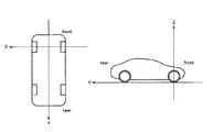
モニタ1は、死角領域の映像を表示するものであり、図2及び図3に示すように、車両100における前方ピラー101の車室内側に取り付けられている。なお、図2及び図3に示す例では、モニタ1は車両100の左側の前方ピラー101に取り付けられているが、右側の前方ピラーに取り付けるようにしてもよいし、左右両方の前方ピラーに取り付けるようにしてもよい。このモニタ1が取り付けられた前方ピラー101が車両100の運転者の視界に入ると、運転者の視界がこの前方ピラー101によって遮られて、死角領域が発生する。モニタ1は、この死角領域の映像を表示することで、前方ピラー101によって発生する死角領域の様子を車両100の運転者が認識できるようにしている。 The
カメラ2は、少なくとも死角領域を含む車両周囲の映像を撮影するものであり、図2に示すように、モニタ1が取り付けられた前方ピラー101の近傍、具体的には、例えば車両100のドアミラー102などに取り付けられている。このカメラ2は、前方ピラー101によって発生する死角領域を十分に撮影可能な画角を有し、前方ピラー101の横幅よりもモニタ1の横幅の方が大きい場合には、モニタ1によって発生する死角領域を十分に撮影可能な画角を有する。なお、カメラ2は、必要な範囲が撮影可能であれば、前方ピラー101の付け根やルーフ、車室内ウィンドウ近辺など、車両100のどこに取り付けられていてもよい。また、複数のカメラで、必要範囲を撮影するようにしてもよい。このカメラ2によって撮影された映像は画像処理装置3に送られ、画像処理装置3において変換処理が行われた後、モニタ1に表示される。 The
画像処理装置3は、カメラ2によって撮影された死角領域の映像を変換して出力映像を作成し、モニタ1に出力映像(変換後の死角領域の映像)を表示させるものであり、例えばコンピュータを用いて所定のプログラムを実行することによって実現される。本実施形態の車両用死角映像表示装置では、特に、この画像処理装置3による映像の変換処理に大きな特徴を有している。すなわち、本実施形態の車両用死角映像表示装置では、モニタ1に表示させる死角領域の映像を、運転者の視点から見た実際の風景とある程度連続した映像とするために、画像処理装置3が、運転者の視点が存在すると推定される基準位置の空間座標と、モニタ1の表示画面を構成する各画素の空間座標とに基づいて、カメラ2により撮影された映像を変換して、モニタ1に表示させる出力映像を作成するようにしている。なお、この画像処理装置3による映像の変換処理については、詳細を後述する。 The
[動作]
以上のように構成される本実施形態の車両用死角映像表示装置では、まず、カメラ2が、死角領域を含む車両周囲の映像を撮影して、その撮影映像のデータをNTSCなどのビデオ映像信号伝送線を用いて画像処理装置3に出力する。画像処理装置3は、カメラ2から撮影映像のデータが送られてくると、これを画素ごとのデータに分割して内部の入力用フレームバッファにストアする。[Operation]
In the vehicle blind spot image display device of the present embodiment configured as described above, first, the
次に、画像処理装置3は、入力用フレームバッファ上の画素のデータを、変換処理の内容にしたがって、出力用フレームバッファ上にコピーしていく。変換処理の内容には、入力用フレームバッファ上の各画素のデータを出力用フレームバッファ上のどこにコピーするかが分かるように、それぞれのアドレスが記述されている。すなわち、変換処理の内容には、出力用フレームバッファ上の各画素と入力用フレームバッファ上の各画素との対応関係が記述されている。画像処理装置3は、この変換処理の内容として記述されている各画素ごとの対応関係をもとに、入力用フレームバッファ上の画素のデータを出力用フレームバッファ上にコピーして、モニタ1に表示させる出力映像を完成させる。 Next, the
次に、画像処理装置3は、出力用フレームバッファの内容、すなわち出力映像のデータを、NTSCなどのビデオ映像信号伝送線を用いてモニタ1に出力する。そして、モニタ1が、この画像処理装置3から送られた出力映像のデータに基づいて表示処理を行うことで、前方ピラーによって発生する死角領域の映像がモニタ1に表示されることになる。本実施形態の車両用死角映像表示装置では、以上の一連の処理をカメラ2による撮影映像のフレームごとに繰り返し行うことで、死角領域の映像を動画としてモニタ1に表示させることができる。なお、以上の一連の処理のなかで、本実施形態の車両用死角映像表示装置に特徴的な部分である画像処理装置3による変換処理以外の部分は、コンピュータを用いた画像処理の分野で公知の技術である。 Next, the
[変換処理の内容]
ここで、本実施形態の車両用死角映像表示装置に特徴的な部分である画像処理装置3による変換処理の内容について具体的に説明する。なお、以下の説明では、図4に示すように、車両の左右方向をX軸、車両の前後方向をY軸、車両の高さ方向をZ軸とした座標系を用いる。この座標系ではXY平面が地面となる。[Contents of conversion process]
Here, the content of the conversion process by the
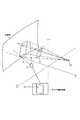
本実施形態の車両用死角映像表示装置において、画像処理装置3での変換処理を行う際には、まず、図5に示すように、基準位置となる運転者の視点位置EPの空間座標EP(x,y,z)を求める。運転者の視点位置EPは、既存の視点位置計測手段を用いて実測により求めることができる。この視点位置計測手段としては、例えば、車室内に設置されたカメラで運転者の顔画像を撮影し、この運転者の顔画像を解析して視点位置EPを求めるものや、車両のルームミラーやドアミラーの角度から運転者の視点位置EPを求めるものなどが考えられる。また、運転者が着座する車両のシート位置をシート位置センサで検出して、検出したシート位置から運転者の視点位置EPを推定するようにしてもよい。また、運転者による入力操作などにより運転者の身長や座高などの身体情報を取得して、この運転者の身体情報に基づいて視点位置EPを推定するようにしてもよい。 In the vehicle blind spot image display device of the present embodiment, when performing the conversion process in the
次に、モニタ1を空間上に存在する表示画素の集合体として考えて、モニタ1の表示画面を構成する各画素L_pの空間座標L_p(x,y,z)を求める。モニタ1を空間上に存在する表示画素の集合体として考えることで、液晶ディスプレイなどのように表示画面が平面状のモニタを用いる場合でも、旧式のCRTのように表示画面が湾曲したモニタを用いる場合でも、同様の処理が可能となる。また、モニタ1としてプロジェクタを用いる場合には、投影面上の画素の空間座標を用いることで、同様の処理が可能となる。 Next, considering the
さらに、死角領域を含む車両周囲の領域の所定位置に基準面を設定する。ここで、基準面は、基準位置である運転者の視点位置EPを中心とした半径Rの球体の外周面として定義される球面状の基準面である。なお、図5においては、便宜上、球面状の基準面の一部を切り出して図示しているが、実際には、運転者の視点位置EPを中心とした半径Rの球体の外周面全域が基準面として設定される。 Further, a reference plane is set at a predetermined position in the area around the vehicle including the blind spot area. Here, the reference plane is a spherical reference plane defined as an outer peripheral surface of a sphere having a radius R centered on the driver's viewpoint position EP, which is the reference position. In FIG. 5, for the sake of convenience, a part of a spherical reference surface is cut out and shown, but in reality, the entire outer peripheral surface of a sphere having a radius R centered on the driver's viewpoint position EP is used as a reference. Set as a face.
そして、図5に示すように、基準位置となる運転者の視点位置EPを始点としてモニタ1の表示画面を構成する各画素L_pを通る半直線と基準面との交点L_cをそれぞれ求める。具体的には、運転者の視点位置EPの空間座標EP(x,y,z)と、モニタ1の表示画面を構成する各画素L_pの空間座標L_p(x,y,z)とから、運転者の視点位置EPとモニタ1の表示画素L_pとの間の距離Dが求められる。そして、基準面が、運転者の視点位置EPを中心とした半径Rの球体の外周面として定められているので、運転者の視点位置EPを始点としてモニタ1の表示画素L_pを通る半直線と基準面との交点L_cは、下記式(1)で求めることができる。なお、この式(1)は、R>Dであれば、運転者の視点位置EPとモニタ1の表示画素L_pとの位置関係によらず常に成立するものであり、この式(1)を用いて、モニタ1の表示画面を構成する各画素L_pに対応した基準面上の全ての交点L_cを求めることができる。 Then, as shown in FIG. 5, the intersection L_c between the half line passing through each pixel L_p constituting the display screen of the
L_c=(L_p−EP)×(R/D)+EP ・・・(1)
以上のようにして、運転者の視点位置EPを始点としてモニタ1の表示画面を構成する各画素L_pを通る半直線と球面状の基準面との交点L_cをそれぞれ求めると、運転者の視点から見たモニタ1の表示画面の基準面上における投影領域Aが求まる。この投影領域Aは、運転者の視点位置EPを基準とした死角領域を球面形状の基準面上の領域として特定したものであり、カメラ2は、この投影領域Aの映像を撮影できるように設定されている。L_c = (L_p−EP) × (R / D) + EP (1)
As described above, when the intersection point L_c between the half line passing through each pixel L_p constituting the display screen of the
次に、カメラ2の取付け位置や向き、レンズ収差などといった各種のカメラパラメータを用いて、球面形状の基準面上における投影領域A内の各交点L_cに対応した、カメラ2の撮影映像における各画素(X_c,Y_c)を特定する。これにより、カメラ2の撮影映像における各画素(X_c,Y_c)とモニタ1の表示画面を構成する各画素L_pとの対応関係、すなわち、入力用フレームバッファ上にストアしたカメラ2の撮影映像における各画素のデータを出力用フレームバッファ上のどこにコピーすればよいかを求めることができ、その対応関係が画像処理装置3による変換処理の内容となる。 Next, each pixel in the captured image of the
本実施形態の車両用死角映像表示装置では、画像処理装置3が、以上のようにして求めた変換処理の内容にしたがって、入力用フレームバッファ上の各画素のデータを出力用フレームバッファ上にコピーしていくことで出力映像が作成される。そして、この出力映像がモニタ1に表示されることになる。このモニタ1に表示される出力映像の映像範囲は、車両の運転者の視点から見たときにモニタ1によって遮蔽される範囲と一致するので、モニタ1に表示される出力映像は、フロントウィンドウやサイドウィンドウを通してみる実際の風景と連続した映像となり、車両の運転者はこの映像の内容を直感的に把握することが可能となる。また、モニタ1は車両の前方ピラーの車室内側に取り付けられているので、車両の運転者は、モニタ1に表示されている出力映像を参照することで、前方ピラーによって発生する死角領域の様子を認識することができる。 In the vehicle blind spot image display device of the present embodiment, the
なお、以上のような変換処理の内容は、出力映像を作成するたびにリアルタイムで計算するようにしてもよいが、車両の運転者の視点位置EPとモニタ1の表示画面を構成する各画素L_pとの位置関係が変わらなければ、変換処理の内容も変化しないので、一度計算した結果を変換テーブルとして画像処理装置3内部のメモリなどに記憶させておき、以降の変換処理では、この変換テーブルに基づいてカメラ2による撮影画像を変換して出力画像を作成するようにしてもよい。また、上述した視点位置計測手段により運転者の視点位置EPが変化したことを検出したときに、以上のような変換処理の内容を新たに計算して、変換テーブルを更新するようにしてもよい。また、複数の視点位置EPに対応した変換テーブルを予め作成しておいて、視点位置計測手段による計測結果に応じてこれらの変換テーブルを使い分けるようにしてもよい。 The content of the conversion process as described above may be calculated in real time every time an output video is created, but the viewpoint position EP of the driver of the vehicle and each pixel L_p constituting the display screen of the
ところで、画像処理装置3が上述した球面状の基準面を用いた演算によって変換処理を行う場合、運転者の視点位置EPとモニタ1の表示画素L_pとの位置関係によっては、球面状の基準面上における交点L_cのZ座標の値がマイナスになることがある。しかしながら、実際には、XY平面は地面であり、Z座標の値がマイナスとなる位置、すなわち地面よりも低い位置に被写体が存在するケースは殆どない。このような場合、交点L_cのZ座標の値がマイナスのまま処理しても、モニタ1に表示される出力映像が多少ゆがむ程度で実用上問題となることは少ないが、歪みを最小限に抑えたい場合には、運転者の視点位置EPから球面状の基準面上におけるZ座標の値がマイナスの交点L_cに向かう半直線上に必ず存在する地面上の点(Z座標の値が0の点)L_c’を求める処理を追加すればよい。 By the way, when the
具体的には、画像処理装置3は、例えば図6に示すように、死角領域を含む車両周囲の領域の所定位置に、上述した球面状の基準面に加えて、地面と一致する平面(Z=0の平面)として定義される平面状の基準面を設定する。そして、運転者の視点位置EPを始点としてモニタ1の表示画面を構成する各画素L_pを通る半直線と球面状の基準面との交点L_cを求めたときに、求めた交点L_cのZ座標の値がマイナスとなる場合には、当該半直線と平面状の基準面との交点L_c’を求め、これをL_cに置き換える。なお、交点L_c’の空間座標は、交点L_cの空間座標をL_c(x_c,y_c,z_c)とし、運転者の視点位置EPの空間座標をEP(x_e,y_e,z_e)、モニタ1の表示画素L_pの空間座標をL_p(x_p,y_p,z_p)とすると、Lc’(cx×(z_e/(z_e−z_c)),cy×(z_e/(z_e−z_c)),0)として表される。そして、運転者の視点位置EPを始点としてモニタ1の表示画面を構成する各画素L_pを通る半直線と球面状基準面、または平面状基準面のとの交点をそれぞれ求めた後に、上述した例と同様の処理を行う。これにより、歪みの少ない出力映像をモニタ1に表示させることができる。 Specifically, as shown in FIG. 6, for example, the
以上の変換処理により作成された出力映像においては、基準面の近くにある物体については歪みなく表示されるが、それ以外の場所にある物体は多少ゆがんで表示されることがある。この問題による影響を最小限にするために、変換処理の演算に用いる基準面として球面状の基準面に加えて平面状の基準面を設定することは、非常に有効な対策である。 In the output video created by the above conversion processing, an object near the reference plane is displayed without distortion, but an object at other locations may be displayed with some distortion. In order to minimize the influence of this problem, it is a very effective measure to set a planar reference surface in addition to a spherical reference surface as a reference surface used for the calculation of the conversion process.
また、モニタ1に表示される出力映像において、運転者にとって特に重要となるのは死角領域に存在する障害物の映像である。そして、この死角領域に存在する障害物を歪みの少ない映像として表示させるには、当該障害物の近くに基準面を設定することも非常に有効である。このような観点から、本実施形態の車両用死角映像表示装置では、車両周囲に存在する障害物を検知して車両から当該障害物までの距離を計測する障害物検知装置を用い、例えば図7に示すように、この障害物検知装置によって計測された車両から障害物までの距離Lを基準として、運転者の視点位置EPから球面状の基準面までの距離、すなわち、球面状の基準面を定義するための球体の半径Rを決定するようにしてもよい。 In the output video displayed on the
すなわち、車両に対する運転者の視点位置EPはほぼ一定と考えられるので、車両から障害物までの距離Lが分かれば、運転者の視点位置EPから障害物までの距離が求められる。そして、この運転者の視点位置EPから障害物までの距離を、運転者の視点位置EPから球面状の基準面までの距離、すなわち、球面状の基準面を定義するための球体の半径Rとすることで、障害物の近傍に球面状の基準面を設定することができ、このように設定した球面状の基準面を用いて上述した変換処理を行うことで、死角領域に存在する障害物を歪みの少ない映像としてモニタ1に表示させることができる。なお、車両から当該障害物までの距離を計測する障害物検知装置としては、例えばミリ波レーダやレーザレーダなど、車両用の障害物検知装置として公知のものが何れも利用可能である。 That is, since the viewpoint position EP of the driver with respect to the vehicle is considered to be substantially constant, if the distance L from the vehicle to the obstacle is known, the distance from the viewpoint position EP of the driver to the obstacle is obtained. The distance from the driver's viewpoint position EP to the obstacle is the distance from the driver's viewpoint position EP to the spherical reference plane, that is, the radius R of the sphere for defining the spherical reference plane. By doing so, a spherical reference surface can be set in the vicinity of the obstacle, and by performing the above-described conversion processing using the spherical reference surface thus set, the obstacle present in the blind spot area Can be displayed on the
[実施形態の効果]
以上、具体的な例を挙げながら詳細に説明したように、本実施形態の車両用死角映像表示装置によれば、画像処理装置3が、運転者の視点が存在すると推定される基準位置の空間座標と、モニタ1の表示画面を構成する各画素の空間座標とに基づいて、カメラ2により撮影された映像を変換して、モニタ1に表示させる出力映像を作成するようにしているので、カメラ2やモニタ1の煩雑な調整作業を行うことなく、車両の前方ピラーにより運転者の視界が遮られることによって生じる死角領域の映像を、運転者の視点からフロントウィンドウやサイドウィンドウを通して見た実際の風景とある程度連続したかたちでモニタ1に表示させることができ、死角領域の映像の内容を運転者に直感的に把握させることができる。[Effect of the embodiment]
As described above in detail with reference to specific examples, according to the vehicle blind spot image display device of the present embodiment, the
また、本実施形態の車両用死角映像表示装置では、画像処理装置3が、車両周囲の領域の所定位置に球面状の基準面を設定し、この球面状の基準面を用いた演算によりモニタ1に表示させる出力映像を作成するようにしているので、演算負荷を過大なものとすることなく、実際の風景とある程度連続した死角領域の映像をモニタ1に適切に表示させることができる。すなわち、画像処理装置3での変換処理の手法としては、車両周囲に複数の平面状の基準面を設定して、これら複数の平面状の基準面を用いて上述した手法と同様の処理を行なうことも考えられるが、このように複数の平面状の基準面を用いて変換処理を行う場合には、運転者の視点が存在すると推定される基準位置を始点としてモニタ1の各表示画像を通過する半直線と各平面状の基準面との交点をそれぞれ求めて、比較演算を行なう必要があり、計算量が膨大なものとなることが懸念される。これに対して、本実施形態の車両用死角映像表示装置では、運転者の視点位置が存在すると推定される基準位置を中心とする球体の外周面として定義される球面状の基準面を設定し、この球面状の基準面を用いて変換処理を行うようにしているので、交点を求める演算が簡略化され、かつ比較演算を行う必要がない。したがって、画像処理装置3での演算負荷を過大なものとすることなく、実際の風景とある程度連続した死角領域の映像をモニタ1に適切に表示させることができ、画像処理装置3をより単純なハードウェアで実現することも可能となる。 Further, in the vehicle blind spot image display device of the present embodiment, the
なお、以上説明した車両用死角映像表示装置は本発明の一適用例であり、本発明が以上の例に限定されるものではなく、本発明に係る技術的思想を逸脱しない範囲であれば、具体的な装置構成や変換処理の細部などにおいて、種々の変更が可能であることは勿論である。例えば、上述した車両用死角映像表示装置では、モニタ1を車両の前方ピラーの車室内側に設置して、前方ピラーにより運転者の視界が遮られることによって生じる死角領域の映像をモニタ1に表示させるようにしているが、モニタ1を他の車両構造物に設置して、その車両構造物により運転者の視界が遮られることによって生じる視界領域の映像をモニタ1に表示させるようにしてもよい。 Note that the vehicle blind spot image display device described above is an application example of the present invention, and the present invention is not limited to the above example, as long as it does not depart from the technical idea of the present invention. It goes without saying that various changes can be made in the specific device configuration and details of the conversion process. For example, in the above-described vehicle blind spot image display device, the
また、上述した車両用死角映像表示装置では、モニタ1に死角領域の映像を常に表示させることを前提としているが、死角領域の映像の表示/非表示を車両周囲の状況に応じて切り替えられるようにしてもよい。すなわち、死角領域の映像を表示することが特に求められるのは、この死角領域に人や他車両などが存在する場合であるので、例えば、近接センサで車両周囲の状況を検出したり、周囲のインフラとの通信により車両周囲の状況を示す情報を取得したりして、その結果に応じて、モニタ1への死角領域の映像の表示/非表示を切り替えるようにしてもよい。勿論、運転者のスイッチ操作などによって、モニタ1への死角領域の映像の表示/非表示を切り替えるようにしてもよい。このように、死角領域の映像の表示/非表示を車両周囲の状況に応じて切り替えるようにした場合には、消費電力の低減といった効果が期待できる。 Further, in the vehicle blind spot image display device described above, it is assumed that the image of the blind spot area is always displayed on the
また、上述した車両用死角映像表示装置では、画像処理装置3での変換処理に用いる基準位置を点(運転者の視点位置EP)として考えて、画像処理装置3が、運転者の視点位置の空間座標とモニタ1の表示画面を構成する各画素の空間座標とに基づいてカメラ2により撮影された映像を変換して、モニタ1に表示させる出力映像を作成するようにしているが、運転者の右目位置と左目位置とを含む空間領域を基準位置として考えて、画像処理装置3が、この空間領域内に存在する運転者の右目位置の空間座標および左目位置の空間座標とモニタ1の表示画面を構成する各画素の空間座標とに基づいてカメラ2により撮影された映像を変換して、モニタ1に表示させる出力映像を作成するようにしてもよい。この場合には、運転者の視覚が右目と左目のどちらが支配的となっているかに拘らず、死角領域の映像を、運転者の視点からフロントウィンドウやサイドウィンドウを通して見た実際の風景とある程度連続したかたちでモニタ1に表示させることができる。 In the vehicle blind spot image display device described above, the
また、運転中における運転者の頭部の動きに応じて運転者の視点が移動する範囲と推定される空間領域を基準位置として考えて、画像処理装置3が、この空間領域内に存在する複数の点の空間位置座標とモニタ1の表示画面を構成する各画素の空間座標とに基づいてカメラ2により撮影された映像を変換して、モニタ1に表示させる出力映像を作成するようにしてもよい。この場合には、頭部の移動により運転者の視点位置がずれたときでも、死角領域の映像を、運転者の視点からフロントウィンドウやサイドウィンドウを通して見た実際の風景とある程度連続したかたちでモニタ1に表示させることができる。 In addition, considering a spatial region estimated as a range in which the driver's viewpoint moves according to the movement of the driver's head during driving as a reference position, the
1 モニタ
2 カメラ
3 画像処理装置
100 車両
101 前方ピラーDESCRIPTION OF
Claims (3)
Translated fromJapanese前記車両構造物に設置された映像表示手段と、
少なくとも前記死角領域を含む車両周囲の領域の映像を撮影する撮影手段と、
運転者の視点が存在すると推定される基準位置の空間座標と、前記映像表示手段の表示画面を構成する各画素の空間座標とに基づいて、前記撮影手段により撮影された映像を変換して、前記映像表示手段に表示させる出力映像を作成する映像変換手段とを備え、
前記映像変換手段は、前記死角領域を含む車両周囲の領域の所定位置に、前記基準位置を中心とする球体の外周面として定義される球面状基準面を設定し、前記基準位置を始点として前記映像表示手段の表示画面を構成する各画素を通る各半直線と前記球面状基準面との交点をそれぞれ求めて、これら各交点に対応する前記撮影手段の撮影映像における各画素を前記撮影手段のパラメータに基づいて特定し、特定した撮影映像における各画素のデータを用いて、前記映像表示手段に表示させる出力映像を作成することを特徴とする車両用死角映像表示装置。In a vehicle blind spot image display device that displays an image of a blind spot region that is generated when a driver's view is blocked by a vehicle structure,
Video display means installed in the vehicle structure;
Photographing means for photographing an image of an area around the vehicle including at least the blind spot area;
Based on the spatial coordinates of the reference position where it is estimated that the driver's viewpoint exists and the spatial coordinates of each pixel constituting the display screen of the video display means, the video shot by the shooting means is converted, Video conversion means for creating an output video to be displayed on the video display means,
The image conversion means sets a spherical reference surface defined as an outer peripheral surface of a sphere centered on the reference position at a predetermined position in a region around the vehicle including the blind spot region, and starts from the reference position as the starting point. An intersection of each half line passing through each pixel constituting the display screen of the image display means and the spherical reference plane is obtained, and each pixel in the photographed image of the photographing means corresponding to each intersection is determined by the photographing means. A vehicle blind spot image display device characterized in that an output image to be displayed on the image display means is created using data of each pixel in the specified captured image specified based on a parameter.
前記映像変換手段は、前記障害物検知手段によって計測された障害物までの距離を基準として、前記基準位置を中心とする球体の半径を決定することを特徴とする請求項1または2に記載の車両用死角映像表示装置。It further comprises obstacle detection means for detecting obstacles around the vehicle and measuring the distance from the vehicle to the obstacle,
The said image conversion means determines the radius of the sphere centering on the said reference position on the basis of the distance to the obstacle measured by the said obstacle detection means. A blind spot image display device for a vehicle.
Priority Applications (3)
| Application Number | Priority Date | Filing Date | Title |
|---|---|---|---|
| JP2005294636AJP4810953B2 (en) | 2005-10-07 | 2005-10-07 | Blind spot image display device for vehicles |
| CNB2006101406516ACN100490530C (en) | 2005-10-07 | 2006-09-29 | Blind spot image display apparatus and method thereof for vehicle |
| US11/542,193US8345095B2 (en) | 2005-10-07 | 2006-10-04 | Blind spot image display apparatus and method thereof for vehicle |
Applications Claiming Priority (1)
| Application Number | Priority Date | Filing Date | Title |
|---|---|---|---|
| JP2005294636AJP4810953B2 (en) | 2005-10-07 | 2005-10-07 | Blind spot image display device for vehicles |
Publications (2)
| Publication Number | Publication Date |
|---|---|
| JP2007104538Atrue JP2007104538A (en) | 2007-04-19 |
| JP4810953B2 JP4810953B2 (en) | 2011-11-09 |
Family
ID=37910869
Family Applications (1)
| Application Number | Title | Priority Date | Filing Date |
|---|---|---|---|
| JP2005294636AExpired - Fee RelatedJP4810953B2 (en) | 2005-10-07 | 2005-10-07 | Blind spot image display device for vehicles |
Country Status (3)
| Country | Link |
|---|---|
| US (1) | US8345095B2 (en) |
| JP (1) | JP4810953B2 (en) |
| CN (1) | CN100490530C (en) |
Cited By (3)
| Publication number | Priority date | Publication date | Assignee | Title |
|---|---|---|---|---|
| US8339252B2 (en) | 2008-06-24 | 2012-12-25 | Toyota Jidosha Kabushiki Kaisha | Blind spot display device and driving support device |
| KR101500196B1 (en)* | 2013-11-14 | 2015-03-06 | 현대자동차주식회사 | Car Display Apparatus for Image of Invisible Region for Driving |
| JP2017502583A (en)* | 2013-12-09 | 2017-01-19 | シゼイ シジブイ カンパニー リミテッド | Multi-screen screening video generation method, storage medium thereof, and video management apparatus using the same |
Families Citing this family (58)
| Publication number | Priority date | Publication date | Assignee | Title |
|---|---|---|---|---|
| US9126533B2 (en)* | 2007-02-23 | 2015-09-08 | Aisin Aw Co., Ltd. | Driving support method and driving support device |
| EP2003019B1 (en)* | 2007-06-13 | 2014-04-23 | Aisin AW Co., Ltd. | Driving assist apparatus for vehicle |
| JP4325705B2 (en)* | 2007-06-15 | 2009-09-02 | 株式会社デンソー | Display system and program |
| US9201504B2 (en)* | 2007-11-29 | 2015-12-01 | Daesung Electric Co., Ltd. | Vehicular glance lighting apparatus and a method for controlling the same |
| KR101351656B1 (en)* | 2012-03-30 | 2014-01-16 | 대성전기공업 주식회사 | Vehicular glance lighting apparatus |
| US9666091B2 (en) | 2008-01-10 | 2017-05-30 | Lifelong Driver Llc | Driver training system |
| US20100076683A1 (en)* | 2008-09-25 | 2010-03-25 | Tech-Cast Mfg Corp. | Car and ship bling spot-free collision avoidance system |
| JP5299688B2 (en)* | 2009-06-03 | 2013-09-25 | アイシン精機株式会社 | Vehicle periphery monitoring method and vehicle periphery monitoring device |
| US8606316B2 (en)* | 2009-10-21 | 2013-12-10 | Xerox Corporation | Portable blind aid device |
| KR100959347B1 (en)* | 2010-02-24 | 2010-05-20 | 조성호 | An apparatus furnishing left-right-rear side view of vehicles |
| DE102010015079A1 (en)* | 2010-04-15 | 2011-10-20 | Valeo Schalter Und Sensoren Gmbh | A method of displaying an image on a display device in a vehicle. Driver assistance system and vehicle |
| WO2011148455A1 (en)* | 2010-05-25 | 2011-12-01 | 富士通株式会社 | Video processing device, video processing method, and video processing program |
| US9363361B2 (en)* | 2011-04-12 | 2016-06-07 | Microsoft Technology Licensing Llc | Conduct and context relationships in mobile devices |
| ES2400496B1 (en)* | 2011-05-18 | 2014-02-11 | Ignacio MARTÍNEZ VITERI | DEVICE FOR ELIMINATING BLIND SPOTS OF A VEHICLE. |
| US10013893B2 (en) | 2011-10-31 | 2018-07-03 | Lifelong Driver Llc | Driver training |
| US9349300B2 (en)* | 2011-10-31 | 2016-05-24 | Lifelong Driver Llc | Senior driver training |
| US8733938B2 (en) | 2012-03-07 | 2014-05-27 | GM Global Technology Operations LLC | Virtual convertible tops, sunroofs, and back windows, and systems and methods for providing same |
| US20130342427A1 (en)* | 2012-06-25 | 2013-12-26 | Hon Hai Precision Industry Co., Ltd. | Monitoring through a transparent display |
| KR101481229B1 (en)* | 2012-10-23 | 2015-01-09 | 현대자동차주식회사 | Method and system for adjusting side-mirror |
| KR101896715B1 (en)* | 2012-10-31 | 2018-09-07 | 현대자동차주식회사 | Apparatus and method for position tracking of peripheral vehicle |
| US10171775B1 (en)* | 2013-05-31 | 2019-01-01 | Vecna Technologies, Inc. | Autonomous vehicle vision system |
| JP6032219B2 (en)* | 2014-01-24 | 2016-11-24 | トヨタ自動車株式会社 | Driving assistance device |
| TWM487864U (en)* | 2014-03-14 | 2014-10-11 | Chi-Yuan Wen | Vision dead angle display device for vehicle front pillar |
| KR101596751B1 (en)* | 2014-09-26 | 2016-02-23 | 현대자동차주식회사 | Method and apparatus for displaying blind spot customized by driver |
| US10614726B2 (en) | 2014-12-08 | 2020-04-07 | Life Long Driver, Llc | Behaviorally-based crash avoidance system |
| US11518309B2 (en) | 2014-12-12 | 2022-12-06 | Serge Hoyda LLC | System and process for viewing in blind spots |
| US11124116B2 (en) | 2014-12-12 | 2021-09-21 | Serge B. HOYDA | System and process for viewing in blind spots |
| US10046703B2 (en) | 2014-12-12 | 2018-08-14 | Serge B. HOYDA | System and process for viewing in blind spots |
| US9654687B2 (en) | 2014-12-24 | 2017-05-16 | Agamemnon Varonos | Panoramic windshield viewer system |
| US10486599B2 (en)* | 2015-07-17 | 2019-11-26 | Magna Mirrors Of America, Inc. | Rearview vision system for vehicle |
| CN107848460A (en)* | 2015-08-10 | 2018-03-27 | 宝马股份公司 | For the system of vehicle, method and apparatus and computer-readable medium |
| US20190031102A1 (en)* | 2016-01-28 | 2019-01-31 | Hon Hai Precision Industry Co., Ltd. | Image display system for vehicle use and vehicle equipped with the image display system |
| JP6669569B2 (en)* | 2016-04-04 | 2020-03-18 | アルパイン株式会社 | Perimeter monitoring device for vehicles |
| WO2018000037A1 (en)* | 2016-06-29 | 2018-01-04 | Seeing Machines Limited | Systems and methods for identifying pose of cameras in a scene |
| FR3053293B1 (en)* | 2016-06-29 | 2019-06-07 | Alstom Transport Technologies | DRIVER ASSISTANCE SYSTEM FOR A VEHICLE, RAILWAY VEHICLE AND METHOD OF USE THEREOF |
| US9959767B1 (en)* | 2016-11-03 | 2018-05-01 | GM Global Technology Operations LLC | Method and apparatus for warning of objects |
| US10343599B2 (en) | 2017-02-10 | 2019-07-09 | Honda Motor Co., Ltd. | Vehicle assembly having luminescent feature and method |
| DE102017114450B4 (en) | 2017-06-29 | 2020-10-08 | Grammer Aktiengesellschaft | Apparatus and method for mapping areas |
| US10384622B2 (en) | 2017-06-30 | 2019-08-20 | Honda Motor Co., Ltd. | Illuminated vehicle emblem |
| US10343600B2 (en) | 2017-06-30 | 2019-07-09 | Honda Motor Co., Ltd. | Illumination of a vehicle storage compartment through electroluminescent material |
| US10668853B2 (en) | 2017-06-30 | 2020-06-02 | Honda Motor Co., Ltd. | Interior A-pillar electroluminescent assembly of a vehicle |
| ES2695757A1 (en)* | 2017-07-06 | 2019-01-10 | Maruri Emilio Placer | Visualization device and procedure to eliminate dead fields of vision in vehicles (Machine-translation by Google Translate, not legally binding) |
| FR3072932B1 (en)* | 2017-10-27 | 2021-08-06 | Psa Automobiles Sa | SCREEN DISPLAY DEVICE FIXED TO PART OF A SYSTEM TO MAKE A MASKING ELEMENT TRANSPARENT. |
| US10482626B2 (en)* | 2018-01-08 | 2019-11-19 | Mediatek Inc. | Around view monitoring systems for vehicle and calibration methods for calibrating image capture devices of an around view monitoring system using the same |
| DE202018102489U1 (en) | 2018-05-04 | 2018-05-14 | Franco Prete | Optical monitoring device for a motor vehicle |
| WO2020013519A1 (en)* | 2018-07-10 | 2020-01-16 | Samsung Electronics Co., Ltd. | Method and system of displaying multimedia content on glass window of vehicle |
| CN111347977B (en)* | 2019-06-05 | 2022-06-10 | 威盛电子股份有限公司 | Vehicle blind spot image display method, device and system |
| US10981507B1 (en) | 2019-11-07 | 2021-04-20 | Focused Technology Solutions, Inc. | Interactive safety system for vehicles |
| CN110901534A (en)* | 2019-11-14 | 2020-03-24 | 浙江合众新能源汽车有限公司 | A-pillar perspective implementation method and system |
| CN111491356B (en)* | 2019-11-27 | 2020-12-08 | 青田县武莲科技有限公司 | Base Station Power Adjustment System |
| CN111739101B (en)* | 2020-05-12 | 2023-06-02 | 太原科技大学 | Device and method for eliminating dead zone of vehicle A column |
| CN112124434A (en)* | 2020-09-01 | 2020-12-25 | 恒大新能源汽车投资控股集团有限公司 | Method and device for realizing transparent A column |
| CN112738496A (en)* | 2020-12-25 | 2021-04-30 | 浙江合众新能源汽车有限公司 | Image processing method, apparatus, system, and computer-readable medium |
| US20220363194A1 (en)* | 2021-05-11 | 2022-11-17 | Magna Electronics Inc. | Vehicular display system with a-pillar display |
| CN113682319B (en)* | 2021-08-05 | 2023-08-01 | 地平线(上海)人工智能技术有限公司 | Camera adjustment method and device, electronic equipment and storage medium |
| CN113815534B (en)* | 2021-11-05 | 2023-05-16 | 吉林大学重庆研究院 | Method for dynamically processing graphics based on coping with position change of human eyes |
| GB2623996A (en)* | 2022-11-03 | 2024-05-08 | Lynley Ashley Adrian | Vehicle panoramic aspect |
| DE102023212433A1 (en)* | 2023-12-11 | 2025-06-12 | Continental Automotive Technologies GmbH | COMPUTER-IMPLEMENTED METHOD FOR DETERMINING A POSITION VECTOR |
Citations (5)
| Publication number | Priority date | Publication date | Assignee | Title |
|---|---|---|---|---|
| WO2000007373A1 (en)* | 1998-07-31 | 2000-02-10 | Matsushita Electric Industrial Co., Ltd. | Method and apparatus for displaying image |
| JP2002083285A (en)* | 2000-07-07 | 2002-03-22 | Matsushita Electric Ind Co Ltd | Image synthesizing apparatus and image synthesizing method |
| JP2002359838A (en)* | 2001-03-28 | 2002-12-13 | Matsushita Electric Ind Co Ltd | Driving support device |
| JP2004021307A (en)* | 2002-06-12 | 2004-01-22 | Matsushita Electric Ind Co Ltd | Driving support device |
| JP2004064131A (en)* | 2002-07-24 | 2004-02-26 | Honda Motor Co Ltd | Display device for vehicles |
Family Cites Families (7)
| Publication number | Priority date | Publication date | Assignee | Title |
|---|---|---|---|---|
| US5982377A (en)* | 1996-04-19 | 1999-11-09 | Fujitsu Limited | Three-dimensional graphic displaying system and method |
| EP2410742A1 (en)* | 1999-04-16 | 2012-01-25 | Panasonic Corporation | Image processing apparatus and monitoring system |
| WO2001028250A1 (en)* | 1999-10-12 | 2001-04-19 | Matsushita Electric Industrial Co., Ltd. | Monitor camera, method of adjusting camera, and vehicle monitor system |
| US7212653B2 (en)* | 2001-12-12 | 2007-05-01 | Kabushikikaisha Equos Research | Image processing system for vehicle |
| US7110021B2 (en)* | 2002-05-31 | 2006-09-19 | Matsushita Electric Industrial Co., Ltd. | Vehicle surroundings monitoring device, and image production method/program |
| KR20040003216A (en)* | 2002-07-02 | 2004-01-13 | 기아자동차주식회사 | A system for monitoring driving-dead space related to a front piller of vehicle |
| JP4744823B2 (en)* | 2004-08-05 | 2011-08-10 | 株式会社東芝 | Perimeter monitoring apparatus and overhead image display method |
- 2005
- 2005-10-07JPJP2005294636Apatent/JP4810953B2/ennot_activeExpired - Fee Related
- 2006
- 2006-09-29CNCNB2006101406516Apatent/CN100490530C/ennot_activeExpired - Fee Related
- 2006-10-04USUS11/542,193patent/US8345095B2/ennot_activeExpired - Fee Related
Patent Citations (5)
| Publication number | Priority date | Publication date | Assignee | Title |
|---|---|---|---|---|
| WO2000007373A1 (en)* | 1998-07-31 | 2000-02-10 | Matsushita Electric Industrial Co., Ltd. | Method and apparatus for displaying image |
| JP2002083285A (en)* | 2000-07-07 | 2002-03-22 | Matsushita Electric Ind Co Ltd | Image synthesizing apparatus and image synthesizing method |
| JP2002359838A (en)* | 2001-03-28 | 2002-12-13 | Matsushita Electric Ind Co Ltd | Driving support device |
| JP2004021307A (en)* | 2002-06-12 | 2004-01-22 | Matsushita Electric Ind Co Ltd | Driving support device |
| JP2004064131A (en)* | 2002-07-24 | 2004-02-26 | Honda Motor Co Ltd | Display device for vehicles |
Cited By (3)
| Publication number | Priority date | Publication date | Assignee | Title |
|---|---|---|---|---|
| US8339252B2 (en) | 2008-06-24 | 2012-12-25 | Toyota Jidosha Kabushiki Kaisha | Blind spot display device and driving support device |
| KR101500196B1 (en)* | 2013-11-14 | 2015-03-06 | 현대자동차주식회사 | Car Display Apparatus for Image of Invisible Region for Driving |
| JP2017502583A (en)* | 2013-12-09 | 2017-01-19 | シゼイ シジブイ カンパニー リミテッド | Multi-screen screening video generation method, storage medium thereof, and video management apparatus using the same |
Also Published As
| Publication number | Publication date |
|---|---|
| US8345095B2 (en) | 2013-01-01 |
| CN1946174A (en) | 2007-04-11 |
| US20070081262A1 (en) | 2007-04-12 |
| CN100490530C (en) | 2009-05-20 |
| JP4810953B2 (en) | 2011-11-09 |
Similar Documents
| Publication | Publication Date | Title |
|---|---|---|
| JP4810953B2 (en) | Blind spot image display device for vehicles | |
| CN110796711B (en) | Panoramic system calibration method and device, computer readable storage medium and vehicle | |
| CN101978694B (en) | Image processing device and method, driving support system, and vehicle | |
| WO2009116328A1 (en) | Image processing device and method, driving support system, and vehicle | |
| WO2011090163A1 (en) | Parameter determination device, parameter determination system, parameter determination method, and recording medium | |
| JP4248570B2 (en) | Image processing apparatus and visibility support apparatus and method | |
| CN109941277A (en) | The method, apparatus and vehicle of display automobile pillar A blind image | |
| JP5093611B2 (en) | Vehicle periphery confirmation device | |
| CN112351242B (en) | Image processing device and image processing method | |
| JP2013216286A (en) | Monitoring device for confirming vehicle surroundings | |
| US11034305B2 (en) | Image processing device, image display system, and image processing method | |
| JP2014093071A (en) | Apparatus and method for tracking position of surrounding vehicle | |
| WO2005079060A1 (en) | Operation support device | |
| US9162621B2 (en) | Parking support apparatus | |
| JP2006044596A (en) | Display device for vehicle | |
| JP2003339044A (en) | Perimeter monitoring device for vehicles | |
| JP2024007203A (en) | Camera system, its control method, and program | |
| JP5173551B2 (en) | Vehicle perimeter monitoring apparatus and camera mounting position / posture information setting correction method applied thereto | |
| JP2022086263A (en) | Information processing equipment and information processing method | |
| JP2018093427A (en) | In-vehicle projector | |
| CN105691300A (en) | Monitoring method and apparatus using a camera | |
| WO2020105698A1 (en) | Image processing device, camera system, and image processing method | |
| JP6269014B2 (en) | Focus control device and focus control method | |
| JP2009083744A (en) | Synthetic image adjustment device | |
| JP4696825B2 (en) | Blind spot image display device for vehicles |
Legal Events
| Date | Code | Title | Description |
|---|---|---|---|
| A621 | Written request for application examination | Free format text:JAPANESE INTERMEDIATE CODE: A621 Effective date:20080827 | |
| A977 | Report on retrieval | Free format text:JAPANESE INTERMEDIATE CODE: A971007 Effective date:20101117 | |
| A131 | Notification of reasons for refusal | Free format text:JAPANESE INTERMEDIATE CODE: A131 Effective date:20101124 | |
| A521 | Request for written amendment filed | Free format text:JAPANESE INTERMEDIATE CODE: A523 Effective date:20110117 | |
| TRDD | Decision of grant or rejection written | ||
| A01 | Written decision to grant a patent or to grant a registration (utility model) | Free format text:JAPANESE INTERMEDIATE CODE: A01 Effective date:20110726 | |
| A01 | Written decision to grant a patent or to grant a registration (utility model) | Free format text:JAPANESE INTERMEDIATE CODE: A01 | |
| A61 | First payment of annual fees (during grant procedure) | Free format text:JAPANESE INTERMEDIATE CODE: A61 Effective date:20110808 | |
| R150 | Certificate of patent or registration of utility model | Ref document number:4810953 Country of ref document:JP Free format text:JAPANESE INTERMEDIATE CODE: R150 Free format text:JAPANESE INTERMEDIATE CODE: R150 | |
| FPAY | Renewal fee payment (event date is renewal date of database) | Free format text:PAYMENT UNTIL: 20140902 Year of fee payment:3 | |
| LAPS | Cancellation because of no payment of annual fees |