JP2007104191A - Power line monitor system using plc coupler - Google Patents
Power line monitor system using plc couplerDownload PDFInfo
- Publication number
- JP2007104191A JP2007104191AJP2005290067AJP2005290067AJP2007104191AJP 2007104191 AJP2007104191 AJP 2007104191AJP 2005290067 AJP2005290067 AJP 2005290067AJP 2005290067 AJP2005290067 AJP 2005290067AJP 2007104191 AJP2007104191 AJP 2007104191A
- Authority
- JP
- Japan
- Prior art keywords
- wireless communication
- electric energy
- data
- slave
- value
- Prior art date
- Legal status (The legal status is an assumption and is not a legal conclusion. Google has not performed a legal analysis and makes no representation as to the accuracy of the status listed.)
- Pending
Links
Images


Landscapes
- Mobile Radio Communication Systems (AREA)
Abstract
Description
Translated fromJapaneseこの発明は、PLC結合器を利用した電力監視システムにおいて、無線を使用し、安価で監視性の高いPLC結合器を用いた電力監視システムに関する。 The present invention relates to a power monitoring system using a PLC, which uses a wireless, inexpensive, and highly monitorable PLC coupler.
従来の電力監視システムとしては、電力監視の警報の通信網を無線化したものがあるが、電力量や電力瞬時値等のデータ伝送網には、有線ネットワークを用いていた(例えば、特許文献1参照)。 As a conventional power monitoring system, there is a wireless power monitoring alarm communication network, but a wired network is used for a data transmission network such as a power amount and an instantaneous power value (for example, Patent Document 1). reference).
従来の電力監視システムは、上述のように構成されていたため、次のような課題があった。
無線通信の電波状況が一時的に悪化した場合に、通信異常が発生すると、警報情報が監視装置に伝達されない場合があった。Since the conventional power monitoring system is configured as described above, there are the following problems.
When the radio wave condition of wireless communication temporarily deteriorates, if communication abnormality occurs, alarm information may not be transmitted to the monitoring device.
また、警報通信網は無線化されていたが、電力消費機器の瞬時値や電力量等の計測データは膨大なデータ量があるため、その伝送には、別途有線のネットワークを使用する必要が発生し、完全に無線化できなかった。このため、レイアウト変更等を行う際に配線工事が必要となり、多大な配線コストを生じさせていた。 In addition, although the alarm communication network was wireless, there is a huge amount of measurement data such as instantaneous values and power consumption of power consuming devices, so it is necessary to use a separate wired network for transmission. And it could not be completely wireless. For this reason, wiring work is required when changing the layout and the like, resulting in a great wiring cost.
また、電力量や瞬時値を無線経由で通信する場合において、異常を報知するための警報信号の通信中に電波状況の悪化によって通信異常が発生すると、通信異常が発生している間の警報信号の積算値が欠落するという課題があった。 In addition, when communicating the amount of electric power or instantaneous value via wireless, if a communication error occurs due to deterioration of radio wave conditions during communication of an alarm signal for notifying an error, an alarm signal while the communication error is occurring There is a problem that the integrated value of is missing.
この発明は、上記のような課題を解決するためになされたものであり、通信異常が生じた場合でも、その間の計測データや、その間に発生した異常を事後的に伝達でき、かつ、安価に構成できる電力監視システムを構築可能にすることを目的とする。 The present invention has been made to solve the above-described problems, and even when a communication abnormality occurs, the measurement data during that time and the abnormality occurring during that time can be transmitted afterwards and at a low cost. The purpose is to make it possible to construct a configurable power monitoring system.
この発明のPLC結合器を用いた電力監視システムは、PLC結合器と、このPLC結合器に接続され、電圧値、電流値または電力量に関するデータ処理を行うメイン処理端末と、前記メイン処理端末に接続された第1無線通信手段と、前記メイン処理端末と前記第1無線通信手段との間でデータ変換を行う第1データ変換手段と、前記第1無線通信手段と無線通信によるデータ通信を行う第2無線通信手段と、電圧値、電流値または電力量を検出するセンサと、
前記センサに接続され、電圧値、電流値または電力量の計測処理を行うスレーブ処理端末と、前記第2無線通信手段と前記スレーブ処理端末との間でデータ変換を行う第2データ変換手段とを備え、前記スレーブ処理端末または前記第2データ変換手段は、電圧値、電流値または電力量、またはこれらの値を処理して得られるデータを格納するデータ格納手段を備える。A power monitoring system using a PLC coupler according to the present invention includes a PLC coupler, a main processing terminal connected to the PLC coupler and performing data processing relating to a voltage value, a current value, or an electric energy, and the main processing terminal. Connected first wireless communication means, first data conversion means for converting data between the main processing terminal and the first wireless communication means, and data communication by wireless communication with the first wireless communication means A second wireless communication means, a sensor for detecting a voltage value, a current value or an electric energy;
A slave processing terminal that is connected to the sensor and performs measurement processing of a voltage value, a current value, or an electric energy; and a second data conversion unit that performs data conversion between the second wireless communication unit and the slave processing terminal. The slave processing terminal or the second data conversion unit includes a data storage unit that stores a voltage value, a current value, an electric energy, or data obtained by processing these values.
一時的に無線通信の異常が発生した場合でも、無線通信が復旧した後に最新の瞬時値をPLC結合器1に送信することができる。このため、無線通信の断絶している間のデータの欠落を抑制することができる。 Even when a wireless communication abnormality occurs temporarily, the latest instantaneous value can be transmitted to the
以下、この発明の各実施の形態に係るPLC(Power Line Communicationの略)結合器を用いた電力監視システムについて説明する。
実施の形態1.
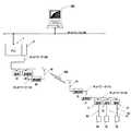
図1は、この発明の実施の形態1に係るPLC結合器を用いた電力監視システムの構成を概略的に示す図である。
図1に示すように、PLC結合器1は、電力監視用PC(Personal Computerの略)300が接続されたPLCネットワーク130に結合されている。
マスタ側に配設されるPLC結合器1には、電力計測用ネットワークインターフェイスカード2が格納されている。この電力計測用ネットワークインターフェイスカード2には、電力計測用ネットワーク100を介してマスタ処理端末である電力計測処理端末10及び第1変換手段であるマスタ変換器20が接続されている。電力計測処理端末10は、電圧値、電流値または電力量に関するデータ処理を行う。Hereinafter, a power monitoring system using a PLC (abbreviation of Power Line Communication) coupler according to each embodiment of the present invention will be described.
FIG. 1 is a diagram schematically showing a configuration of a power monitoring system using a PLC coupler according to
As shown in FIG. 1, the
The
マスタ変換器20には、ネットワーク110を介して第1無線通信手段である無線機30が接続されている。この無線機30は、無線通信用のアンテナ40を備える。
なお、PLC結合器1は、電力値や後述する電力値等の異常の有無を表示する表示部(図1には図示せず)を備える。この表示部は、PLC結合器1の外部から視認可能に配設されており、電力値を表示する表示部と、電圧値や電力量の積算値の異常の有無を表示する表示部とから構成される。後者については、表示色を切り替えることにより、異常を報知するように構成されている。その役割については、図3を用いて説明する。The
The
第2無線通信手段であるスレーブ側の無線機31は、無線通信用のアンテナ41を備え、無線電波(計測データ搬送波)200による計測データをマスタ側の無線機30から受信する。
無線機31には、ネットワーク111を介して第2変換手段であるスレーブ変換器21が接続され、このスレーブ変換器21には、電力計測用ネットワーク101を介してスレーブ処理端末である電力計測処理端末11、12及び13が接続されている。
また、電力計測処理端末11、12及び13には、センサ50、51及び52がケーブル60、61及び62を介してそれぞれ図1に示すように接続されている。The slave-
A
In addition,
これら電力計測処理端末11、12及び13は、センサ50、51及び52によって検出される電圧値、電流値または電力量の計測処理を行うデータ処理部と、センサ50、51及び52によって検出される電圧値、電流値または電力量が前記所定の閾値を超えた場合に異常と判定する異常判定部と、電圧値、電流値または電力量が異常判定部によって異常と判定された場合に、異常フラグを格納する異常状態格納部とを備える。 These power
また、電力計測処理端末11、12及び13は、電圧値、電流値または電力量、またはこれらの値を処理して得られるデータ(例えば、以下で説明する電圧値の瞬時値や電力量の積算値)を格納するデータ格納手段を備えるように構成してもよく、また、このデータ格納手段がスレーブ変換器21に含まれるように構成してもよい。この点については、図2(a)ないし(c)を用いて後述する。 In addition, the power
次に、この発明の実施の形態1に係るPLC結合器を用いた電力監視システムにおけるデータ通信動作について説明する。
PLC結合器1は、電力計測用ネットワークインターフェイスカード2、電力計測用ネットワーク100、マスタ変換器20、無線機30、スレーブ側無線機31、スレーブ変換器21、電力計測用ネットワーク111を経由して、計測したいデータを収集するコマンドを電力計測処理端末11、12及び13に発行する。Next, a data communication operation in the power monitoring system using the PLC coupler according to
The
電力計測処理端末11、12及び13は、電圧値、電流値、及び、電力量の瞬時値及び積算値を計測すると共に、これらの計測値を所定の閾値と比較しながら監視し、いずれかの値に異常がある場合には、異常をスレーブ変換器21に報知する機能を有する。
具体的には、電力計測処理端末11、12及び13は、ケーブル60、61及び62を介してセンサ50、51及び52から電力量や電流の瞬時値等の計測データを予め収集して格納しておき、マスタ側からコマンドを受けると、ネットワーク101を通じて計測データをスレーブ変換器21に伝達する。The power
Specifically, the power
スレーブ変換器21は、電力計測処理端末11、12または13から計測データを受信すると、これらの計測データを、電力計測用ネットワーク111、無線機31、マスタ側無線機30、マスタ変換器20、電力計測用ネットワーク100及び電力計測用ネットワークインターフェイスカード2を介して、PLC結合器1によって指定されたコマンドに対する計測データをPLC結合器1に伝送する。 When the
PLC結合器1は、上述のようにして各端末11、12または13から計測データを収集し、PLCネットワーク130を介して、収集した計測データを電力監視パソコン300に伝送する。
また、スレーブ側の端末11、12及び13は、上述したように電圧値、電流値、及び、電力量等の計測データの積算値処理機能、及び、瞬時値処理機能を有すると共に、計測データに異常がないかを監視する異常監視機能を有する。
以下、それぞれの機能について説明する。The
Further, as described above, the slave-
Hereinafter, each function will be described.
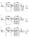
図2は、この発明の実施の形態1に係るPLC結合器を用いた電力監視システムにおける積算値処理と瞬時値処理の処理内容を示す図である。
なお、ここでは、説明の都合上、端末11のみがデータ処理部の機能に基づく処理を行う場合について説明するが、端末12または13のいずれが異常監視を行っても同様の処理が行われる。FIG. 2 is a diagram showing processing contents of integrated value processing and instantaneous value processing in the power monitoring system using the PLC coupler according to
Here, for convenience of explanation, the case where only the
まず、図2(a)に示すように、スレーブ変換器21にパルス積算機能を有する端末11Aを接続し、電力量を積算する場合について説明する。
端末11Aは、電力量を表すパルスを繰り返し計測しており、現在のカウント値(以下、現カウント値と記す)、前回のカウント値(以下、前カウント値と記す)、及び、カウント値の積算値(以下、積算値と記す)を計測・積算する機能を有し、また、各値を格納するエリアを有する。このエリアは、メモリで構成されるものであり、データ格納手段としての役割を担う。
また、図2に示すように、スレーブ変換器21は、現カウント値、前カウント値、及び、積算値を格納するスレーブ変換器データエリアを有する。このスレーブ変換器データエリアも、メモリで構成されるものであり、データ格納手段としての役割を担う。First, as shown in FIG. 2A, a case where the
The
As shown in FIG. 2, the
端末11Aにパルスが印加されると、端末11Aは、端末11A内の現カウント値のエリアにカウント値が格納される。さらに、端末11Aは、前カウント値と現カウント値を合計し、積算(累積)カウント値を自動的に算出して積算値のエリアに書き込む。 When the pulse is applied to the
PLC結合器1は、マスタ変換器20から無線200を経由してスレーブ変換器21及び端末11Aに積算値を要求する。この要求を受け取った端末11Aは、パルスの積算値をスレーブ変換器21に返答データとして伝送する。
スレーブ変換器データエリア21bは、相手端末が端末11Aであれば、積算値のみを有効に設定し、データを積算値エリアに直接格納する。このようにしてスレーブ変換器データエリアに格納した積算値のデータを無線200経由にてマスタ変換器20に送信する。マスタ変換器20は、PLC結合器1に積算値を伝送し、PLC結合器1はアプリケーションにて電力量の積算値を表示する。The
In the slave
次に、図2(b)に示すように、パルス積算機能を有しない端末11Bをスレーブ変換器21に接続する場合について説明する。
端末11Bは、電力量を表すパルスを繰り返し計測しており、電力量の現カウント値を格納するエリアを有する。Next, as shown in FIG. 2B, a case where the terminal 11B not having the pulse integration function is connected to the
The terminal 11B repeatedly measures a pulse representing the electric energy and has an area for storing the current count value of the electric energy.
端末11Bにパルスが印加されると、端末11B内の現カウント値のエリアにカウント値が格納される。PLC結合器1は、マスタ変換器20から無線200を経由してスレーブ変換器21及び端末11Bに電力量の積算値を要求する。
この要求を受け取った端末11Bは、電力量のパルスの積算値をスレーブ変換器21に返答データとして伝送する。When a pulse is applied to the terminal 11B, the count value is stored in the area of the current count value in the terminal 11B. The
Upon receiving this request, the terminal 11B transmits the integrated value of the electric energy pulse to the
スレーブ変換器データエリア21bでは、相手端末が端末11Bであれば、電力量の現カウント値、電力量の前カウント値、及び、電力量の積算値を全て有効に設定し、まずスレーブ変換器データエリア21b内の現カウント値にパルスデータを格納する。
スレーブ変換器21では、前カウント値と積算値が有効になっているため、現カウント値+前カウント値=積算値を算出し、その算出結果である積算値を無線200経由でマスタ変換器20に伝送する。積算値を受け取ったマスタ変換器20は、積算値をマスタ変換器データエリア20bに格納する。
マスタ変換器20は、PLC結合器1に積算値を伝送し、PLC結合器1はアプリケーションによって電力量の積算値を表示する。In the slave
In the
次に、図2(c)を用いて瞬時値処理について説明する。
端末11Cは、電圧値の瞬時値を繰り返し計測しており、電圧値の現在値を格納するエリアを有する。
端末11Cに電圧値が印加されると、端末11Cのデータ格納エリアに電圧の瞬時値が現在値として格納される。
PLC結合器1は、マスタ変換器20から無線200を経由してスレーブ変換器21及び端末11Cに電圧の瞬時値を要求する。この要求を受け取った端末11Cは、データ格納エリアに電圧の瞬時値を格納してある電圧の瞬時値をスレーブ変換器21に返答データとして伝送する。Next, the instantaneous value processing will be described with reference to FIG.
The terminal 11C repeatedly measures the instantaneous value of the voltage value and has an area for storing the current value of the voltage value.
When a voltage value is applied to the terminal 11C, an instantaneous voltage value is stored as a current value in the data storage area of the terminal 11C.
The
スレーブ変換器21は、スレーブ変換器データエリア21bの現在値のエリアのみを有効に設定しておき、端末11Cから伝送された現在値をエリアに格納し、格納した電圧の現在値を無線200経由でマスタ変換器20に送信する。
マスタ変換器20は、PLC結合器1に瞬時値を返信データとして伝送し、PLC結合器1はアプリケーションにて表示等の処理を実行する。The
The
以上のように、この発明の実施の形態1に係るPLC結合器を用いた電力計測システムによれば、電圧値、電流値または電力量、あるいはこれらを処理して得られるデータ(例えば、上述した電圧値の瞬時値や電力量の積算値、その他のデータでもよい)をスレーブ側の端末11ないし13またはスレーブ変換器21に格納するので、一時的に無線通信の異常が発生した場合でも、無線通信が復旧した後に最新の瞬時値をPLC結合器1に送信することができる。このため、無線通信の断絶している間のデータの欠落を抑制することができる。 As described above, according to the power measurement system using the PLC coupler according to the first embodiment of the present invention, the voltage value, the current value, the power amount, or the data obtained by processing these (for example, as described above) The instantaneous value of the voltage value, the integrated value of the electric energy, and other data may be stored in the
次に、この発明の実施の形態1に係るPLC結合器を用いた電力監視システムにおける異常監視処理について説明する。
図3は、この発明の実施の形態1に係るPLC結合器を用いた電力監視システムにおける異常監視処理の流れとマスタ側及びスレーブ側でのフラグの状況を示す処理状況説明図である。Next, an abnormality monitoring process in the power monitoring system using the PLC coupler according to
FIG. 3 is a process status explanatory diagram showing the flow of abnormality monitoring processing and the status of flags on the master side and slave side in the power monitoring system using the PLC coupler according to
具体的には、この図3は、PLC結合器1の異常報知表示部の表示状態と、マスタ側の変換器20及びスレーブ側の変換器21にそれぞれ設けられたマスタ変換器警報状態エリア20a及びスレーブ変換器警報状態エリア21aのフラグの状態と、異常監視を行う端末11によって検知される異常発生の有無の状態とを時系列的に示す。 Specifically, FIG. 3 shows the display state of the abnormality notification display section of the
マスタ変換器警報状態エリア20aには、スレーブ警報状態フラグ及びマスタ警報状態フラグが格納される。
スレーブ変換器警報状態エリア21aには、端末警報状態フラグ、スレーブ警報状態フラグ及びマスタ警報状態フラグが格納される。
これらのフラグは警報1点毎に設けられており、複数点の警報を取り込むことが可能である。In the master converter alarm state area 20a, a slave alarm state flag and a master alarm state flag are stored.
In the slave converter
These flags are provided for each alarm, and a plurality of alarms can be captured.
ここで、端末11が異常を検知したときの処理について図3を用いて説明する。
図3に示す状態1は、異常要因が発生した状態である。
この異常要因は例えば、電圧値の瞬時値や電力量の異常である。
電圧値の瞬時値や電力量の異常を検出可能な端末11によって瞬時値や電力量の異常が検出されると、マスタ変換器20は、スレーブ変換器警報状態エリア21a内の端末警報状態フラグをONにする(0(オフ)から1(オン)になる)。Here, processing when the terminal 11 detects an abnormality will be described with reference to FIG.
This abnormality factor is, for example, an instantaneous value of the voltage value or an abnormality in the electric energy.
When the terminal 11 capable of detecting the instantaneous value of the voltage value or the abnormality of the electric energy detects the abnormality of the instantaneous value or the electric energy, the
このように端末警報状態フラグがONになると、スレーブ変換器21は、状態2に示すようにスレーブ警報状態フラグをONにする。マスタ変換器20とスレーブ変換器21は、無線200経由にて一定周期で通信しているため、無線経由にてマスタ変換器警報状態エリア20a内のスレーブ警報状態フラグに書き込みが行われ、マスタ変換器警報状態エリア20a内のスレーブ警報状態フラグがONになる。すなわち、異常フラグに基づく異常情報がマスタ処理端末である電力計測処理端末10に伝達される。 When the terminal alarm state flag is turned on in this way, the
このようにスレーブ警報状態フラグがONになると、マスタ変換器20は、状態3に示すようにPLC結合器1に異常発生通知を伝達する。
PLC結合器1は、異常発生通知を受けると、アプリケーションにより、表示部を異常発生表示に切り替える。
更に、マスタ変換器20は、PLC結合器1に警報を通知した後に、マスタ警報状態フラグをONにする。
マスタ変換器20とスレーブ変換器21の間では、無線経由にて一定周期で通信している為、無線経由にてスレーブ変換器警報状態エリア21a内のマスタ警報状態フラグをONにする。When the slave alarm state flag is turned on as described above, the
When receiving the abnormality occurrence notification, the
Furthermore, after notifying the
Since the
ここで、スレーブ変換器警報状態エリア21a内のスレーブ警報状態フラグがOFFされる条件は、マスタ警報状態フラグがONで、かつ、端末警報状態フラグがOFFになったことである。
従って、状態4では、マスタ警報状態フラグ及び端末警報状態フラグが共にONであり、スレーブ警報状態フラグはONのまま保持される。Here, the condition that the slave alarm state flag in the slave converter
Therefore, in state 4, both the master alarm state flag and the terminal alarm state flag are ON, and the slave alarm state flag is kept ON.
次に示す状態5は、異常要因が無くなった状態である。
この状態では、端末11から異常発生通知が通知されなくなるため、スレーブ変換器警報状態エリア21a内の端末警報状態フラグがOFFとなり、スレーブ警報状態フラグのOFF条件が成立する。
続いて、マスタ変換器20とスレーブ変換器21との間の無線通信により、マスタ変換器警報状態エリア20a内のスレーブ警報状態フラグがOFFにされる。State 5 shown below is a state in which there are no abnormal factors.
In this state, since the terminal 11 is not notified of the occurrence of abnormality, the terminal alarm state flag in the slave converter
Subsequently, the slave alarm state flag in the master converter alarm state area 20a is turned OFF by wireless communication between the
次に、状態6では、マスタ変換器20がPLC結合器1に異常要因がなくなったことを通知すると共に、マスタ変換器警報状態エリア20a内のマスタ警報状態フラグをOFFする。
PLC結合器1は、異常要因がなくなった通知を受けると、異常表示を解除する。また、スレーブ変換器21内のマスタ警報状態フラグは無線経由にてOFFされる。Next, in the state 6, the
When the
以上、この発明の実施の形態1に係るPLC結合器を用いた電力監視システムによれば、スレーブ側で異常状態を示すフラグを格納するので、無線通信に一時的な通信異常が発生した場合においても、無線通信の復旧後に異常発生通知を行うことが可能である。
なお、以上では、電圧値の瞬時値または電力量の積算値を計測する場合について説明したが、電流値の瞬時値を計測するように構成してもよい。As described above, according to the power monitoring system using the PLC coupler according to the first embodiment of the present invention, the flag indicating the abnormal state is stored on the slave side, so that when a temporary communication abnormality occurs in the wireless communication, In addition, it is possible to notify the occurrence of abnormality after the wireless communication is restored.
In addition, although the case where the instantaneous value of voltage value or the integrated value of electric energy was measured was demonstrated above, you may comprise so that the instantaneous value of an electric current value may be measured.
実施の形態2.
図4は、この発明の実施の形態2に係るPLC結合器を用いた電力監視システムのシステム構成を示す図である。
無線電波(計測データ搬送波)200および201を介してマスタ側無線機30に複数のスレーブ側無線機31、32等を接続している。すなわち、実施の形態1に係るPLC結合器を用いた電力監視システムにスレーブ側無線機32を付加した構成である。
スレーブ側無線機31については、実施の形態1におけるスレーブ側無線機31と同様の構成であり、その説明は省略する。Embodiment 2. FIG.
FIG. 4 is a diagram showing a system configuration of a power monitoring system using a PLC coupler according to Embodiment 2 of the present invention.
A plurality of slave-
The slave
スレーブ側無線機32は、無線電波(計測データ搬送波)201による計測データを受信するためのアンテナ42を備え、ネットワーク112を介して変換器22をスレーブ側無線機31、32と接続している。
また、変換器22と電力計測用の端末14、15及び16を電力計測用ネットワーク102で接続している。端末14、15及び16には、電力計測用のセンサ53、54及び55がケーブル63、64及び65を介してそれぞれ接続されている。
このように、この発明の実施の形態2に係るPLC結合器を用いた電力監視システムによれば、マスタ側とスレーブ側を無線電波で接続しているので、電力計測用ネットワークの系統数や電力計測処理端末の数を増やすことが可能である。The slave-
Further, the
As described above, according to the power monitoring system using the PLC coupler according to the second embodiment of the present invention, the master side and the slave side are connected by wireless radio waves, so the number of power measurement networks and power It is possible to increase the number of measurement processing terminals.
実施の形態3.
図5は、この発明の実施の形態3に係るPLC結合器を用いた電力監視システムのシステム構成を示す図である。
この発明の実施の形態3に係るPLC結合器を用いた電力監視システムは、マスタ側無線機30とスレーブ側無線機31の間に、無線電波(計測データ搬送波)200および202によって搬送される計測データを中継するための中継アンテナ43を備える。
その他の構成は実施の形態1に係るPLC結合器を用いた電力監視システムの構成に準じる。Embodiment 3 FIG.
FIG. 5 is a diagram showing a system configuration of a power monitoring system using a PLC coupler according to Embodiment 3 of the present invention.
In the power monitoring system using the PLC coupler according to Embodiment 3 of the present invention, measurement carried by radio waves (measurement data carrier waves) 200 and 202 between the master
Other configurations conform to the configuration of the power monitoring system using the PLC coupler according to the first embodiment.
このように、この発明の実施の形態3に係るPLC結合器を用いた電力監視システムは、中継アンテナ43を備えることにより、無線通信距離を増大させているので、異常の発生をより確実にメイン側に伝達することが可能となり、無線ネットワークの信頼性を向上させることができる。 As described above, the power monitoring system using the PLC coupler according to the third embodiment of the present invention includes the
また、この発明によれば、データ欠けを生じさせることなく電力監視する為の積算値や瞬時値のデータ通信を行なうことができるため、無線ネットワークの信頼性を向上させることができる。
また、電力監視する為の積算値や瞬時値のデータ通信と異常を伝達する通信を全て無線にて確実に行うことができるため、無線を適用することによりレイアウト変更時等における配線工事が不要となり、ケーブル配線配管工事費の削減や工事期間の短縮を図ることができる。In addition, according to the present invention, since data communication of integrated values and instantaneous values for power monitoring can be performed without causing data loss, the reliability of the wireless network can be improved.
In addition, the integrated value and instantaneous value data communication for power monitoring and the communication that transmits the abnormality can all be reliably performed wirelessly, so the use of wireless makes wiring work unnecessary when changing the layout, etc. In addition, it is possible to reduce the cost of cable wiring and piping work and shorten the construction period.
また、無線による通信を行うため、1つのマスタ側無線機30に複数のスレーブ側無線機を接続することができ、従来は一系統の電力計測用ネットワークしか繋がらなかったシステムでも、無線通信を行うことにより1:n(nは整数)の複数の系統の既存電力計測用ネットワークを接続でき、電力計測用ネットワークの系統数や電力計測処理端末の数を増やすことができる。
また、無線部にリピータを接続すれば、無線部分の到達距離を増やすことができる。In addition, since wireless communication is performed, a plurality of slave-side wireless devices can be connected to one master-
In addition, if a repeater is connected to the radio unit, the reach of the radio part can be increased.
1 PLC結合器、2 電力計測用ネットワークインターフェイスカード、10 電力計測処理端末、11、11A、11B、11C、12、13、14、15、16 端末、20 マスタ変換器、20a マスタ変換器警報状態エリア、20b マスタ変換器データエリア、21、22 スレーブ変換器、21a スレーブ変換器警報状態エリア、21b スレーブ変換器データエリア、30 マスタ側無線機、31、32 スレーブ側無線機、40、41、42 アンテナ、43 中継アンテナ、50、51、52、53、54、55 センサ、60、61、62、63、64、65 ケーブル、81 表示部、100、101、102 電力計測用ネットワーク、110、111、112 ネットワーク、130 ネットワーク、200 無線、300 電力監視パソコンPC 電力監視用。 1 PLC coupler, 2 network interface card for power measurement, 10 power measurement processing terminal, 11, 11A, 11B, 11C, 12, 13, 14, 15, 16 terminal, 20 master converter, 20a master converter alarm status area , 20b Master converter data area, 21, 22 Slave converter, 21a Slave converter alarm status area, 21b Slave converter data area, 30 Master side radio, 31, 32 Slave side radio, 40, 41, 42 Antenna , 43 Relay antenna, 50, 51, 52, 53, 54, 55 Sensor, 60, 61, 62, 63, 64, 65 Cable, 81 Display unit, 100, 101, 102 Network for power measurement, 110, 111, 112 Network 130
Claims (4)
Translated fromJapaneseこのPLC結合器に接続され、電圧値、電流値または電力量に関するデータ処理を行うメイン処理端末と、
前記メイン処理端末に接続された第1無線通信手段と、
前記メイン処理端末と前記第1無線通信手段との間でデータ変換を行う第1データ変換手段と、
前記第1無線通信手段と無線通信によるデータ通信を行う第2無線通信手段と、
電圧値、電流値または電力量を検出するセンサと、
前記センサに接続され、電圧値、電流値または電力量の計測処理を行うスレーブ処理端末と、
前記第2無線通信手段と前記スレーブ処理端末との間でデータ変換を行う第2データ変換手段と
を備え、前記スレーブ処理端末または前記第2データ変換手段は、電圧値、電流値または電力量、またはこれらの値を処理して得られるデータを格納するデータ格納手段を備えることを特徴とするPLC結合器を用いた電力監視システム。A PLC coupler;
A main processing terminal that is connected to the PLC coupler and performs data processing relating to voltage value, current value or electric energy;
First wireless communication means connected to the main processing terminal;
First data conversion means for performing data conversion between the main processing terminal and the first wireless communication means;
Second wireless communication means for performing data communication by wireless communication with the first wireless communication means;
A sensor for detecting a voltage value, a current value or an electric energy;
A slave processing terminal connected to the sensor and performing a measurement process of a voltage value, a current value, or an electric energy;
Second data conversion means for performing data conversion between the second wireless communication means and the slave processing terminal, the slave processing terminal or the second data conversion means, the voltage value, current value or electric energy, Alternatively, a power monitoring system using a PLC coupler, comprising data storage means for storing data obtained by processing these values.
前記センサによって検出される電圧値、電流値または電力量が前記所定の閾値を超えた場合に異常と判定する異常判定部と、
電圧値、電流値または電力量が異常判定部によって異常と判定された場合に、異常フラグを格納する異常状態格納部と
を備え、前記第2無線通信手段を通じて、前記異常フラグに基づく異常情報を前記マスタ処理端末に伝達することを特徴とする請求項1記載のPLC結合器を用いた電力監視システム。The slave processing terminal stores and holds a predetermined threshold value of voltage value, current value or electric energy,
An abnormality determination unit that determines an abnormality when a voltage value, a current value, or an electric energy detected by the sensor exceeds the predetermined threshold;
An abnormality state storage unit that stores an abnormality flag when a voltage value, a current value, or an electric energy is determined to be abnormal by the abnormality determination unit, and the abnormality information based on the abnormality flag is transmitted through the second wireless communication unit. 2. The power monitoring system using a PLC coupler according to claim 1, wherein the power monitoring system transmits the data to the master processing terminal.
Priority Applications (1)
| Application Number | Priority Date | Filing Date | Title |
|---|---|---|---|
| JP2005290067AJP2007104191A (en) | 2005-10-03 | 2005-10-03 | Power line monitor system using plc coupler |
Applications Claiming Priority (1)
| Application Number | Priority Date | Filing Date | Title |
|---|---|---|---|
| JP2005290067AJP2007104191A (en) | 2005-10-03 | 2005-10-03 | Power line monitor system using plc coupler |
Publications (1)
| Publication Number | Publication Date |
|---|---|
| JP2007104191Atrue JP2007104191A (en) | 2007-04-19 |
Family
ID=38030704
Family Applications (1)
| Application Number | Title | Priority Date | Filing Date |
|---|---|---|---|
| JP2005290067APendingJP2007104191A (en) | 2005-10-03 | 2005-10-03 | Power line monitor system using plc coupler |
Country Status (1)
| Country | Link |
|---|---|
| JP (1) | JP2007104191A (en) |
Cited By (2)
| Publication number | Priority date | Publication date | Assignee | Title |
|---|---|---|---|---|
| WO2009123404A1 (en)* | 2008-04-04 | 2009-10-08 | 주) 한국통신 | In-building communication-relay system using power-line communication and method thereof |
| CN101819712A (en)* | 2010-05-05 | 2010-09-01 | 无锡科尔华电子有限公司 | Collecting and monitoring method and system of wireless comprehensive data of transmission line |
- 2005
- 2005-10-03JPJP2005290067Apatent/JP2007104191A/enactivePending
Cited By (2)
| Publication number | Priority date | Publication date | Assignee | Title |
|---|---|---|---|---|
| WO2009123404A1 (en)* | 2008-04-04 | 2009-10-08 | 주) 한국통신 | In-building communication-relay system using power-line communication and method thereof |
| CN101819712A (en)* | 2010-05-05 | 2010-09-01 | 无锡科尔华电子有限公司 | Collecting and monitoring method and system of wireless comprehensive data of transmission line |
Similar Documents
| Publication | Publication Date | Title |
|---|---|---|
| CN101523680B (en) | Electrical fault limiting system | |
| JP6245353B2 (en) | COMMUNICATION DEVICE, ITS CONTROL METHOD, AND PROGRAM | |
| CN107063484A (en) | A kind of power distribution network In-Line Temperature Measure System and method | |
| WO2017199427A1 (en) | Equipment monitoring device, wireless sensor, and collecting station | |
| KR20200059388A (en) | Electricity Information Management System | |
| JP2007333674A (en) | Cable connection diagnostic device and diagnostic system | |
| JP6794019B2 (en) | Abnormal communication system of distribution board | |
| KR101344411B1 (en) | Using smart device for the error of a local power plant diagnosis device and method | |
| JP2007104191A (en) | Power line monitor system using plc coupler | |
| CN111273571A (en) | Equipment running state monitoring method, device and system, storage medium and equipment | |
| CN118837667A (en) | Cable fault positioning analysis monitoring system and method, program product and storage medium | |
| KR20110125579A (en) | Fault Diagnosis Method and Fault Diagnosis Device of Field Power Equipment using Smart Terminal | |
| CN107255767A (en) | A kind of electrical equipment safety monitoring system in power plant | |
| CN109029579A (en) | A kind of slope stability monitoring system | |
| KR101707964B1 (en) | Electrical power distribution board system | |
| CN211321008U (en) | Safety grid | |
| JP2005077360A (en) | Lifetime diagnosis apparatus, life diagnosis system and life diagnosis method for digital protection relay | |
| CN203606937U (en) | Dual system mistaken ringing prevention alarm control device | |
| US20210159025A1 (en) | Method for calculating the contact state of an electrical switch, and electrical switch with such a method | |
| CN205450227U (en) | Highly reliable long -range fire control device power monitored control system | |
| CN213781204U (en) | Mine environment monitoring system based on wireless sensor network | |
| JP2013081292A (en) | Measurement information transmission system | |
| CN214192302U (en) | Multi-terminal visualization system of gantry crane | |
| KR20140107727A (en) | Monitoring mehtod based on USN for large equipment of shipyard | |
| CN202602634U (en) | Optical power monitoring system with zigbee wireless networking function |