JP2007097143A - Imaging system for capturing multimedia image - Google Patents
Imaging system for capturing multimedia imageDownload PDFInfo
- Publication number
- JP2007097143A JP2007097143AJP2006190840AJP2006190840AJP2007097143AJP 2007097143 AJP2007097143 AJP 2007097143AJP 2006190840 AJP2006190840 AJP 2006190840AJP 2006190840 AJP2006190840 AJP 2006190840AJP 2007097143 AJP2007097143 AJP 2007097143A
- Authority
- JP
- Japan
- Prior art keywords
- image
- media
- capturing
- optical
- linear sensor
- Prior art date
- Legal status (The legal status is an assumption and is not a legal conclusion. Google has not performed a legal analysis and makes no representation as to the accuracy of the status listed.)
- Pending
Links
Images


Classifications
- H—ELECTRICITY
- H04—ELECTRIC COMMUNICATION TECHNIQUE
- H04N—PICTORIAL COMMUNICATION, e.g. TELEVISION
- H04N1/00—Scanning, transmission or reproduction of documents or the like, e.g. facsimile transmission; Details thereof
- H04N1/024—Details of scanning heads ; Means for illuminating the original
- H04N1/028—Details of scanning heads ; Means for illuminating the original for picture information pick-up
- H04N1/02815—Means for illuminating the original, not specific to a particular type of pick-up head
- H04N1/02845—Means for illuminating the original, not specific to a particular type of pick-up head using an elongated light source, e.g. tubular lamp, LED array
- H04N1/0285—Means for illuminating the original, not specific to a particular type of pick-up head using an elongated light source, e.g. tubular lamp, LED array in combination with at least one reflector which is in fixed relation to the light source
- H—ELECTRICITY
- H04—ELECTRIC COMMUNICATION TECHNIQUE
- H04N—PICTORIAL COMMUNICATION, e.g. TELEVISION
- H04N1/00—Scanning, transmission or reproduction of documents or the like, e.g. facsimile transmission; Details thereof
- H04N1/024—Details of scanning heads ; Means for illuminating the original
- H04N1/028—Details of scanning heads ; Means for illuminating the original for picture information pick-up
- H04N1/02815—Means for illuminating the original, not specific to a particular type of pick-up head
- H04N1/02845—Means for illuminating the original, not specific to a particular type of pick-up head using an elongated light source, e.g. tubular lamp, LED array
- H04N1/0286—Means for illuminating the original, not specific to a particular type of pick-up head using an elongated light source, e.g. tubular lamp, LED array in combination with a light integrating, concentrating or defusing cavity
- H—ELECTRICITY
- H04—ELECTRIC COMMUNICATION TECHNIQUE
- H04N—PICTORIAL COMMUNICATION, e.g. TELEVISION
- H04N1/00—Scanning, transmission or reproduction of documents or the like, e.g. facsimile transmission; Details thereof
- H04N1/024—Details of scanning heads ; Means for illuminating the original
- H04N1/028—Details of scanning heads ; Means for illuminating the original for picture information pick-up
- H04N1/02815—Means for illuminating the original, not specific to a particular type of pick-up head
- H04N1/02845—Means for illuminating the original, not specific to a particular type of pick-up head using an elongated light source, e.g. tubular lamp, LED array
- H04N1/0287—Means for illuminating the original, not specific to a particular type of pick-up head using an elongated light source, e.g. tubular lamp, LED array using a tubular lamp or a combination of such lamps
- H—ELECTRICITY
- H04—ELECTRIC COMMUNICATION TECHNIQUE
- H04N—PICTORIAL COMMUNICATION, e.g. TELEVISION
- H04N1/00—Scanning, transmission or reproduction of documents or the like, e.g. facsimile transmission; Details thereof
- H04N1/024—Details of scanning heads ; Means for illuminating the original
- H04N1/028—Details of scanning heads ; Means for illuminating the original for picture information pick-up
- H04N1/02815—Means for illuminating the original, not specific to a particular type of pick-up head
- H04N1/02885—Means for compensating spatially uneven illumination, e.g. an aperture arrangement
- H04N1/0289—Light diffusing elements, e.g. plates or filters
- H—ELECTRICITY
- H04—ELECTRIC COMMUNICATION TECHNIQUE
- H04N—PICTORIAL COMMUNICATION, e.g. TELEVISION
- H04N1/00—Scanning, transmission or reproduction of documents or the like, e.g. facsimile transmission; Details thereof
- H04N1/024—Details of scanning heads ; Means for illuminating the original
- H04N1/028—Details of scanning heads ; Means for illuminating the original for picture information pick-up
- H04N1/03—Details of scanning heads ; Means for illuminating the original for picture information pick-up with photodetectors arranged in a substantially linear array
- H04N1/031—Details of scanning heads ; Means for illuminating the original for picture information pick-up with photodetectors arranged in a substantially linear array the photodetectors having a one-to-one and optically positive correspondence with the scanned picture elements, e.g. linear contact sensors
- H04N1/0318—Integral pick-up heads, i.e. self-contained heads whose basic elements are a light-source, a lens array and a photodetector array which are supported by a single-piece frame
- H—ELECTRICITY
- H04—ELECTRIC COMMUNICATION TECHNIQUE
- H04N—PICTORIAL COMMUNICATION, e.g. TELEVISION
- H04N1/00—Scanning, transmission or reproduction of documents or the like, e.g. facsimile transmission; Details thereof
- H04N1/04—Scanning arrangements, i.e. arrangements for the displacement of active reading or reproducing elements relative to the original or reproducing medium, or vice versa
- H04N1/12—Scanning arrangements, i.e. arrangements for the displacement of active reading or reproducing elements relative to the original or reproducing medium, or vice versa using the sheet-feed movement or the medium-advance or the drum-rotation movement as the slow scanning component, e.g. arrangements for the main-scanning
- H04N1/121—Feeding arrangements
- H04N1/1215—Feeding using one or more cylindrical platens or rollers in the immediate vicinity of the main scanning line
- H—ELECTRICITY
- H04—ELECTRIC COMMUNICATION TECHNIQUE
- H04N—PICTORIAL COMMUNICATION, e.g. TELEVISION
- H04N1/00—Scanning, transmission or reproduction of documents or the like, e.g. facsimile transmission; Details thereof
- H04N1/04—Scanning arrangements, i.e. arrangements for the displacement of active reading or reproducing elements relative to the original or reproducing medium, or vice versa
- H04N1/12—Scanning arrangements, i.e. arrangements for the displacement of active reading or reproducing elements relative to the original or reproducing medium, or vice versa using the sheet-feed movement or the medium-advance or the drum-rotation movement as the slow scanning component, e.g. arrangements for the main-scanning
- H04N1/121—Feeding arrangements
- H04N1/1235—Feeding a sheet past a transparent plate; Details thereof
- H04N1/124—Plate shape
- H—ELECTRICITY
- H04—ELECTRIC COMMUNICATION TECHNIQUE
- H04N—PICTORIAL COMMUNICATION, e.g. TELEVISION
- H04N1/00—Scanning, transmission or reproduction of documents or the like, e.g. facsimile transmission; Details thereof
- H04N1/04—Scanning arrangements, i.e. arrangements for the displacement of active reading or reproducing elements relative to the original or reproducing medium, or vice versa
- H04N1/12—Scanning arrangements, i.e. arrangements for the displacement of active reading or reproducing elements relative to the original or reproducing medium, or vice versa using the sheet-feed movement or the medium-advance or the drum-rotation movement as the slow scanning component, e.g. arrangements for the main-scanning
- H04N1/121—Feeding arrangements
- H04N1/125—Feeding arrangements the sheet feeding apparatus serving an auxiliary function, e.g. as a white reference
- H—ELECTRICITY
- H04—ELECTRIC COMMUNICATION TECHNIQUE
- H04N—PICTORIAL COMMUNICATION, e.g. TELEVISION
- H04N2201/00—Indexing scheme relating to scanning, transmission or reproduction of documents or the like, and to details thereof
- H04N2201/0077—Types of the still picture apparatus
- H04N2201/0081—Image reader
- H—ELECTRICITY
- H04—ELECTRIC COMMUNICATION TECHNIQUE
- H04N—PICTORIAL COMMUNICATION, e.g. TELEVISION
- H04N2201/00—Indexing scheme relating to scanning, transmission or reproduction of documents or the like, and to details thereof
- H04N2201/024—Indexing scheme relating to scanning, transmission or reproduction of documents or the like, and to details thereof deleted
- H04N2201/028—Indexing scheme relating to scanning, transmission or reproduction of documents or the like, and to details thereof deleted for picture information pick-up
- H04N2201/03—Indexing scheme relating to scanning, transmission or reproduction of documents or the like, and to details thereof deleted for picture information pick-up deleted
- H04N2201/031—Indexing scheme relating to scanning, transmission or reproduction of documents or the like, and to details thereof deleted for picture information pick-up deleted deleted
- H04N2201/03104—Integral pick-up heads, i.e. self-contained heads whose basic elements are a light source, a lens and a photodetector supported by a single-piece frame
- H04N2201/03108—Components of integral heads
- H04N2201/03137—Reflecting element downstream of the scanned picture elements
- H—ELECTRICITY
- H04—ELECTRIC COMMUNICATION TECHNIQUE
- H04N—PICTORIAL COMMUNICATION, e.g. TELEVISION
- H04N2201/00—Indexing scheme relating to scanning, transmission or reproduction of documents or the like, and to details thereof
- H04N2201/024—Indexing scheme relating to scanning, transmission or reproduction of documents or the like, and to details thereof deleted
- H04N2201/028—Indexing scheme relating to scanning, transmission or reproduction of documents or the like, and to details thereof deleted for picture information pick-up
- H04N2201/03—Indexing scheme relating to scanning, transmission or reproduction of documents or the like, and to details thereof deleted for picture information pick-up deleted
- H04N2201/031—Indexing scheme relating to scanning, transmission or reproduction of documents or the like, and to details thereof deleted for picture information pick-up deleted deleted
- H04N2201/03104—Integral pick-up heads, i.e. self-contained heads whose basic elements are a light source, a lens and a photodetector supported by a single-piece frame
- H04N2201/03108—Components of integral heads
- H04N2201/03141—Photodetector lens
- H—ELECTRICITY
- H04—ELECTRIC COMMUNICATION TECHNIQUE
- H04N—PICTORIAL COMMUNICATION, e.g. TELEVISION
- H04N2201/00—Indexing scheme relating to scanning, transmission or reproduction of documents or the like, and to details thereof
- H04N2201/024—Indexing scheme relating to scanning, transmission or reproduction of documents or the like, and to details thereof deleted
- H04N2201/028—Indexing scheme relating to scanning, transmission or reproduction of documents or the like, and to details thereof deleted for picture information pick-up
- H04N2201/03—Indexing scheme relating to scanning, transmission or reproduction of documents or the like, and to details thereof deleted for picture information pick-up deleted
- H04N2201/031—Indexing scheme relating to scanning, transmission or reproduction of documents or the like, and to details thereof deleted for picture information pick-up deleted deleted
- H04N2201/03104—Integral pick-up heads, i.e. self-contained heads whose basic elements are a light source, a lens and a photodetector supported by a single-piece frame
- H04N2201/03108—Components of integral heads
- H04N2201/03145—Photodetector
- H—ELECTRICITY
- H04—ELECTRIC COMMUNICATION TECHNIQUE
- H04N—PICTORIAL COMMUNICATION, e.g. TELEVISION
- H04N2201/00—Indexing scheme relating to scanning, transmission or reproduction of documents or the like, and to details thereof
- H04N2201/024—Indexing scheme relating to scanning, transmission or reproduction of documents or the like, and to details thereof deleted
- H04N2201/028—Indexing scheme relating to scanning, transmission or reproduction of documents or the like, and to details thereof deleted for picture information pick-up
- H04N2201/03—Indexing scheme relating to scanning, transmission or reproduction of documents or the like, and to details thereof deleted for picture information pick-up deleted
- H04N2201/031—Indexing scheme relating to scanning, transmission or reproduction of documents or the like, and to details thereof deleted for picture information pick-up deleted deleted
- H04N2201/03104—Integral pick-up heads, i.e. self-contained heads whose basic elements are a light source, a lens and a photodetector supported by a single-piece frame
- H04N2201/0315—Details of integral heads not otherwise provided for
- H04N2201/03162—Original guide plate
- H—ELECTRICITY
- H04—ELECTRIC COMMUNICATION TECHNIQUE
- H04N—PICTORIAL COMMUNICATION, e.g. TELEVISION
- H04N2201/00—Indexing scheme relating to scanning, transmission or reproduction of documents or the like, and to details thereof
- H04N2201/04—Scanning arrangements
- H04N2201/0402—Arrangements not specific to a particular one of the scanning methods covered by groups H04N1/04 - H04N1/207
- H04N2201/0404—Scanning transparent media, e.g. photographic film
Landscapes
- Engineering & Computer Science (AREA)
- Multimedia (AREA)
- Signal Processing (AREA)
- Facsimile Scanning Arrangements (AREA)
- Light Sources And Details Of Projection-Printing Devices (AREA)
- Facsimile Heads (AREA)
- Optical Systems Of Projection Type Copiers (AREA)
Abstract
Description
Translated fromJapanese本発明は、光学領域に関するものであって、特に、反射、及び、透過メディアからイメージを捕捉するスキャン装置に関するものである。 The present invention relates to the optical domain, and in particular to a scanning device that captures images from reflective and transmissive media.
人々のコンピュータ、PDA、携帯電話、ファクシミリ、及び、その他の装置間のテキスト、グラフィック、及び、イメージ情報等の様々なデータの送受信への依存も高まりが、コミュニケーションネットワークを発展させている。多くの業者がシステムを構築し、電子手段によりデータの保存、伝送、受信、更には、ハードコピー(hard copy)を実行している。多くの状況において、電子型のデータによる作業の実行は便利であり、例えば、データは非常に速い速度で同僚やその他の会社の手に渡る。 Increasing reliance on the transmission and reception of various data such as text, graphics, and image information between people's computers, PDAs, mobile phones, facsimiles, and other devices has increased communication networks. Many vendors build systems and store, transmit, receive, and even hard copy data using electronic means. In many situations, it is convenient to perform work with electronic data, for example, data is delivered to colleagues and other companies at a very fast rate.
しかし、現在多くのスキャンシステムは通常、相当な大きさと電力が必要で、電子型式のハードコピーに対し高品質の複製結果を提供する。例えば、デスクトップスキャナー(desktop scanners)と多機能周辺機器multi−function peripherals 、MFP) は、平面走査ソリューション(flatbed scanning solutions)を使用するので、往々にして、デスクトップ領域を占有する。このような方式は、スキャンしたいドキュメントと同じ大きさの平面の平台プラテンガラスが必要である。この他、あるシステムは小さい光学表面によりドキュメントを伝送して、平面プラテンを減少させることができる。しかし、この方式は、機械式のメディアプロセッサが余分に必要となる。また、メディアは光学ウィンドウの上方を通過するので、使用時間が長くなると、光学ウィンドウも損傷を受けやすい。よって、交換可能な光学ウィンドウが必要である。この他、脆弱なメディアは固定式の光学ウィンドウを通過することにより損壊する恐れがある。 However, many current scanning systems typically require substantial size and power, and provide high quality replication results for electronic hard copies. For example, desktop scanners and multifunction peripherals (multifunction peripherals, MFP) often use flat scanning solutions and therefore occupy the desktop area. Such a scheme requires a flat platen glass that is the same size as the document to be scanned. In addition, some systems can transmit a document with a small optical surface to reduce the planar platen. However, this method requires an extra mechanical media processor. Further, since the media passes above the optical window, the optical window is easily damaged when the usage time is extended. Therefore, a replaceable optical window is necessary. In addition, fragile media can be damaged by passing through a fixed optical window.
更に、多くの小型スキャンシステムは屈折率分布型(gradient index 、grin)レンズアレイを使用し、非常に短い焦点距離と非常に限られた焦点深さを有する。これらのシステム中、メディアを適当な焦点面に定位させないと、人々が容認できるイメージ品質が獲得できない。 In addition, many miniature scanning systems use gradient index (grind) lens arrays and have very short focal lengths and very limited depths of focus. In these systems, the image quality acceptable to people cannot be obtained unless the media is localized to the appropriate focal plane.
よって、精確、且つ、効果的に反射光と透光メディアからのイメージを捕捉する小型のスキャン装置が必要とされる。 Therefore, there is a need for a small scanning device that accurately and effectively captures images from reflected and translucent media.
上述の問題を達成するため、本発明は、メディアイメージを捕捉するイメージシステムを提供し、光学モジュールを有し、スキャンメカニズムに対し旋転する管状プラテンを利用して、メディア物件のスキャンイメージを生成することを目的とする。 To achieve the above-described problems, the present invention provides an image system for capturing media images and utilizes a tubular platen having an optical module and rotating relative to a scanning mechanism to generate a scanned image of a media article. For the purpose.
本発明は、イメージシステムを提供し、照明システムと光学モジュールを結合することにより、メディアのスキャンを実行し、照明システムは、管状拡散プラテン、光源、反射器からなる。光学モジュールは、イメージ素子を囲繞旋転する旋転光学プラテンを有し、且つ、イメージ素子は、レンズアレイ、光学素子、線的センサーアレイ、相互接続回路、及び、ハウジング、からなり、光学プラテンは透過型で、イメージ素子が透過型メディアのイメージを補足できると共に、透過型メディアを精確に最適な焦点面に定位させる。 The present invention provides an image system and performs a media scan by combining an illumination system and an optical module, the illumination system comprising a tubular diffuse platen, a light source, and a reflector. The optical module has a rotating optical platen that rotates around the image element, and the image element includes a lens array, an optical element, a linear sensor array, an interconnection circuit, and a housing, and the optical platen is transmissive. Thus, the image element can capture the image of the transmissive medium, and accurately position the transmissive medium at the optimum focal plane.
本発明は、透過型メディアイメージを捕捉するイメージシステムを提供し、照明システムは、透過型メディアの一側に設置されて、透過型メディアのバックライトとなり、且つ、イメージシステムは、このバックライトの透過型メディアを捕捉し、透過型光学プラテンはイメージシステムを囲繞して旋転し、透過型メディアの位置を定位させる。 The present invention provides an image system that captures a transmissive media image, wherein the illumination system is installed on one side of the transmissive media to provide a backlight for the transmissive media, and the image system includes the backlight. The transmissive media is captured, and the transmissive optical platen rotates around the image system to localize the location of the transmissive media.
本発明は、イメージシステムを提供し、照明と光学のサブシステムは独立した旋転光学プラテン内に包括され、イメージシステムは、不透光のドキュメントが光学モジュールの位置の同一辺から受光する時、不透過ドキュメントに対しスキャン作業を実行する。 The present invention provides an image system in which the illumination and optical subsystems are contained within a separate rotating optical platen, and the image system is not sensitive when an opaque document is received from the same side of the optical module position. Perform scan operations on transparent documents.
本発明のメディアイメージを捕捉するイメージシステムは、照明システムと光学モジュールからなり、両者の結合によりメディアのスキャンを実行する。照明システムは、管状拡散プラテン、光源、反射器からなる。光学モジュールは、イメージ素子を囲繞旋転する旋転光学プラテンを有し、且つ、イメージ素子は、レンズアレイ、光学素子、線的センサーアレイ、相互接続回路、及び、ハウジング、からなり、光学プラテンは透過型で、イメージ素子が透過型メディアのイメージを補足できると共に、透過型メディアを精確に最適な焦点面に定位させる。 The image system for capturing a media image according to the present invention includes an illumination system and an optical module, and scans the media by combining the two. The illumination system consists of a tubular diffuse platen, a light source and a reflector. The optical module has a rotating optical platen that rotates around the image element, and the image element includes a lens array, an optical element, a linear sensor array, an interconnection circuit, and a housing, and the optical platen is transmissive. Thus, the image element can capture the image of the transmissive medium, and accurately position the transmissive medium at the optimum focal plane.
本発明により、精確、且つ、効果的に反射光と透光メディアからのイメージを捕捉する小型のスキャン装置が提供される。 The present invention provides a compact scanning device that captures images from reflected light and translucent media accurately and effectively.
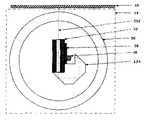
図1は、本発明の好ましい実施例によるイメージシステム10の断面図である。イメージシステム10は、照明システム12と光学モジュール14からなる。照明システム12と光学モジュール14は、通常一緒に使用されて、透過メディア(transparent media)16に対しスキャンを実行する。 FIG. 1 is a cross-sectional view of an
照明システム12は三つの主要素子からなり、管状拡散プラテン20、光源22、及び、反射器24である。管状拡散プラテン20の材質は、例えば、ガラス、或いは、プラスチックで、光源22からの光線を拡散し、透過型メディア16を精確に好ましい焦点面に定位させることができるものである。光源は、制御可能な光源で、例えば、蛍光ランプの白色光、或いは、日本板硝子(Nippon Sheet Glass)、或いは、米国のピクソン(Pixon Corporation)社による発光ダイオード照明光導体(light guide)の有色光である。また、反射器24は白色光、或いは、銀白光反射器で、光線を反射させると共に、透過型メディアに向かって照射する。 The
光学モジュール14は、旋転光学プラテン30とハウジング40からなる。旋転光学プラテン30は、イメージ素子を囲繞して旋転し、イメージ素子は、レンズアレイ32、光学素子34、線的センサーアレイ36、相互接続回路38、及び、ハウジング40、からなり、光学プラテン30は光学プラスチック、或いは、ガラスからなり、透過型で、イメージ素子が透過型メディア16のイメージを補足できると共に、透過型メディア16を精確に最適な焦点面に定位させる。イメージ素子のレンズアレイ32は単一倍率(unity magnification)のレンズアレイで、例えば、日本板硝子、或いは、三菱レーヨン(Mitsubishi Rayon)による屈折率分布型レンズアレイで、屈折率分布型レンズアレイを使用するレンズアレイは、二個の反射光が光学素子34を通過後、透過型メディア16のイメージを線的センサーアレイ(linear sensor array)36上で構築する。また、光学素子34は褶曲光学経路(folded optical path)の実施例中に使用でき、非褶曲光学経路(non−folded optical path)の実施例中、光学素子34を除去してもよい。また、光学素子34は、イメージ素子の尺寸を縮小することができ、旋転光学プラテン30の尺寸も更に小さくなり、光学素子34は、光学プリズム、或いは、複数の多ミラー(multiple mirrors)を含む。これらの多ミラーは、一つ、或いは、それ以上の反射の光学経路により設計され、ハウジング40上に設置される。線的センサーアレイ36は、光センサーの線的アレイを有し、画素とも称され、電荷結合装置(charge−coupled device、CCD)、シーモス(Complementary Metal Oxide Semiconductor、CMOS)技術、或いは、その他の光センサー技術により製作される。線的センサーアレイ36中の画素素子は、光エネルギーを電荷に転換し、電圧信号を生成し、デジタル化した後、透過型メディア16上のスキャンラインに対応するデジタルデータを提供する。この他、相互接続回路38が使用されて、線的センサーアレイ36からの出力信号を制御、取得する。また、ハウジング40は、イメージ素子の全素子を容納、排列でき、これらの素子は、周辺、或いは、迷光(stray light)の光学経路から隔離し、その構造の完全性を提供し、外部の機械素子を接続して、旋転光学プラテン30内の光学素子34が適当に定位するようにする。照明システム12、光学モジュール14と透過型メディア16、管状拡散プラテン20と旋転光学プラテン30は、制御システムにより制御を協調させる。この制御システムは、電子、ファームウェア、ソフト、電気機械部品、或いは、それらの群の組み合わせで、イメージシステム10は外部の各素子、或いは、ストレージ(storage)に接続される。 The
図1Bは、照明システム12の照明形態と光学モジュール14の透過型メディア16に対する光学経路の細部断面図である。多辺形50は光源22と透過型メディア16間を介する照明空間で、光源22に存在する光線は、直線A−Bに沿い、主に、直線C−D方向に伝送されて、透過型メディア16を照明し、直線C−Dの中央は最高輝度を生成する。直線52は、透過型メディア16の物面から線的センサーアレイ36で生成されるイメージ面の光学路径の中心線を示す。 FIG. 1B is a detailed cross-sectional view of the illumination path of the
図1Cは、イメージシステム10の位置のスキャン操作期間での移動を示す図である。透過型メディア16は、矢印60方向のように、左から右へ移動すると同時に、旋転拡散プラテン20は矢印62方向のように反時計回りで、旋転拡散プラテン30は矢印64方向のように時計回りである。本発明のその他の実施例中、運行する方向は反対でもよい。これらの実施例中、透過型メディア16は、矢印60の反対方向に移動し、同時に、拡散プラテン20は、矢印62の反対方向に時計回りで旋転し、光学プラテン30は、矢印64の反対方向に反時計回りに旋転する。 FIG. 1C is a diagram illustrating movement of the position of the
図2は、本発明の実施例による非褶曲光学経路を結合した光学システムの断面図である。非褶曲光学経路は、光学経路中心線152により設計される。本実施例中、透過型メディア16からの光線は、旋転光学プラテン30を通過し、レンズアレイ32により捕捉、焦点し、その後、線的センサーアレイ36に進入する。 FIG. 2 is a cross-sectional view of an optical system combining non-curved optical paths according to an embodiment of the present invention. The non-curved optical path is designed by the
図3は、本発明の実施例による二個以上の反射器を有する光学プリズム134を結合した光学システムの断面図である。図3ではハウジングが示されておらず、光学プリズム134が銀をめっきし、且つ、レンズアレイ32と線的センサーアレイ36の介面以外の場所が不透光である場合、ハウジングは消去、或いは、減少してもよい。光学経路は、光学路径中心線252により設計される。本実施例中、透過型メディア16からの光線は、旋転光学プラテン30を通過し、レンズアレイ32により捕捉され、光学プリズム134内で三回反射し、その後、線的センサーアレイ36に集光する。 FIG. 3 is a cross-sectional view of an optical system combining an
図4は、本発明の実施例による照明と光学サブシステムを、一つの独立した旋転光学プラテン30中に包括させたことを示す図である。本実施例は、不透過ドキュメントをスキャンし、このドキュメントは、光学モジュール114の位置の同一辺から受光する。光学モジュール114は、図1の光学モジュール14の全ての素子を含み、光源122、反射器124からなる照明素子も含む。図4は、光学モジュール114の照明形態と光学モジュール114のメディア116に相対する光学路径を示す。多辺形150は、光源122とメディア116間を介する照明空間を示し、光源122に存在する光線は、直線E−Fに沿い、且つ、主に、直線G−Hの方向に伝送されて、照明は反射光メディア116を照明すると共に、直線G−Hの中央で最高輝度を生成する。メディア116から散射される光線は、旋転光学プラテン30を穿過し、レンズアレイ32と光学素子34により捕捉し、線的センサーアレイ36に集光する。光学経路中心線352は、メディア116から線的センサーアレイ36までの光学経路を示す。線的センサーアレイ36は、アレイ中の各画素上で光線を電荷に転換し、電荷の量は光線の量と比例し、且つ、電荷は累積でき、同時に、余分な電子装置から読み取り、電圧に転換して出力する。 FIG. 4 is a diagram illustrating the illumination and optical subsystem according to an embodiment of the present invention contained in one independent rotating
図5は、本発明の実施例による二個の光学モジュールを示し、つまり、上光学モジュール114Aと下光学モジュール114Bを使用し、透光、或いは、不透光のメディア216に対しスキャンする多重スキャン功能を実行する。照明が、上光学モジュール114A、或いは、下光学モジュール114Bから提供されるのかは各種メディアが透光か不透光かによる。メディア216が透過なら、上光学モジュール114Aはメディア316のバックライト照明を提供し、下光学モジュール114Bは、イメージ捕捉を実行する。メディア216が不透光の場合、上光学モジュール114Aはメディア216の頂側をスキャンし、下光学モジュール114Bは、メディア216の底側をスキャンする。また、これらのモジュールが同時スキャン、或いは、連続スキャンを実行するのは、イメージシステムの功能によって決まる。 FIG. 5 shows two optical modules according to an embodiment of the present invention, that is, multiple scans using an upper
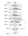
図6は、本発明の実施例による光学システムを使用する方法のフローチャートである。本方法の各工程は、それぞれ、以下のようである。工程600で、まず、スキャン作業の初期化を実行し、その後、工程602で、メディアの位置をスキャンラインの外側に定位させ、続いて、工程604〜608において、スキャンシステムの補正を実行する。補正の工程については、工程604で、消灯し、所謂ダーク補正(dark calibration)で、ダーク補正は照明が欠乏する下でデータを測量し、センサーの変異に対し補償を実行する。工程606中、照明を点灯する。続いて、工程608で、白補正を実行し、照明システムと光学システム中の変異を測量する。ダーク補正と白補正のデータは、システム中で使用し、システムの各項変異を除去すると共に、スキャン品質を改善する。その後、工程610で、メディアはイメージ経路中に移動する。工程612で、現在のスキャンラインのデータを捕捉し、その後、工程614中、スキャンライン毎に、メディアに対しスキャンを進める。工程616で、スキャン作業が完成したか確認する。スキャン作業は予め決定されたスキャンライン数量により実行するか、或いは、システムはその他の方式によりスキャン作業が完成したか確認する。例えば、メディアが不足する状況に対し、独立したセンサーを使用するか、或いは、スキャンデータを検査することにより、メディアが不足するか確認する。スキャン作業が未完成の場合、工程612で、別のスキャンラインの捕捉を実行する。システムが工程616〜618の順に従って、スキャンの完成を確認した後、この方法のスキャン作業を完成する。 FIG. 6 is a flowchart of a method of using an optical system according to an embodiment of the present invention. Each step of the method is as follows. In step 600, the scan operation is first initialized, and then in step 602, the position of the media is localized outside the scan line, and in steps 604 to 608, the scan system is corrected. The correction process is turned off in step 604, so-called dark calibration, where dark correction measures the data under lack of illumination and performs compensation for sensor variations. During step 606, the illumination is turned on. Subsequently, in step 608, white correction is performed to measure variations in the illumination system and the optical system. Dark correction and white correction data are used in the system to eliminate system term variations and improve scan quality. Thereafter, at step 610, the media moves into the image path. In step 612, data for the current scan line is captured, and then in step 614, the scan is advanced on the media for each scan line. In step 616, it is confirmed whether the scanning operation is completed. The scan operation is executed according to a predetermined scan line quantity, or the system confirms whether the scan operation is completed by another method. For example, for a situation where the medium is insufficient, it is confirmed whether the medium is insufficient by using an independent sensor or by inspecting scan data. If the scan operation is incomplete, at step 612, another scan line is captured. After the system confirms the completion of the scan according to the order of steps 616 to 618, the scan operation of the method is completed.
本発明では好ましい実施例を前述の通り開示したが、これらは決して本発明に限定するものではなく、当該技術を熟知する者なら誰でも、本発明の精神と領域を脱しない範囲内で各種の変動や潤色を加えることができ、従って本発明の保護範囲は、特許請求の範囲で指定した内容を基準とする。 In the present invention, preferred embodiments have been disclosed as described above. However, the present invention is not limited to the present invention, and any person who is familiar with the technology can use various methods within the spirit and scope of the present invention. Variations and moist colors can be added, so the protection scope of the present invention is based on what is specified in the claims.
10 イメージシステム
12 照明システム
14 光学モジュール
16 透過型メディア
20 管状拡散プラテン
22 光源
24 反射器
30 旋転光学プラテン
32 レンズアレイ
34 光学素子
36 線性センサーアレイ
40 ハウジング
50 多辺形
52 直線
60 矢印
62 矢印
64 矢印
114 光学モジュール
114A 上光学モジュール
114B 下光学モジュール
116 メディア
122 光源
124 反射器
134 光学プリズム
150 多辺形
152 光学経路中心線
154 光学経路中心線
216 メディア
352 光学経路中心線DESCRIPTION OF
Claims (28)
Translated fromJapaneseメディアのスキャンイメージを生成する光学モジュールからなり、前記光学モジュールは、
スキャンメカニズムと、
前記スキャンメカニズムに対し旋転する管状光学プラテンと、
からなることを特徴とするメディアイメージを捕捉するイメージシステム。An image system for capturing media images,
An optical module for generating a scanned image of the media, the optical module comprising:
A scanning mechanism,
A tubular optical platen that rotates relative to the scanning mechanism;
An image system for capturing media images characterized by comprising:
光線を生成する光源と、
前記メディアに向けて前記光線を反射する反射器と、
イメージ素子と、
からなることを特徴とする請求項1に記載のメディアイメージを捕捉するイメージシステム。The scanning mechanism is
A light source for generating rays;
A reflector that reflects the light beam toward the media;
An image element;
The image system for capturing a media image according to claim 1, comprising:
前記メディアのイメージを捕捉する線的センサーアレイと、
前記メディアの前記イメージを前記線的センサーアレイ上に構築するレンズアレイと、
前記線的センサーアレイの出力信号を制御、及び、取得する相互接続回路と、
前記イメージ素子の複数の素子を容納、排列するハウジングと、
からなることを特徴とする請求項2に記載のメディアイメージを捕捉するイメージシステム。The image element is
A linear sensor array for capturing an image of the media;
A lens array that builds the image of the media on the linear sensor array;
An interconnect circuit for controlling and acquiring the output signal of the linear sensor array;
A housing for accommodating and arranging a plurality of elements of the image element;
The image system for capturing a media image according to claim 2, comprising:
前記イメージ素子の尺寸を縮小する光学素子を有することを特徴とする請求項3に記載のメディアイメージを捕捉するイメージシステム。The image element further comprises:
The image system for capturing a media image according to claim 3, further comprising an optical element that reduces a size of the image element.
前記メディアを照明する照明システムと、
前記メディアのイメージを捕捉する光学モジュールからなり、前記光学モジュールは、
イメージ素子と、
前記イメージ素子に対し旋転し、前記メディアを精確に適当な焦点面に定位させる管状光学プラテンと、
からなることを特徴とするメディアイメージを捕捉するイメージシステム。An image system for capturing media images,
An illumination system for illuminating the media;
An optical module for capturing an image of the media, the optical module comprising:
An image element;
A tubular optical platen that rotates relative to the image element to position the media accurately in a suitable focal plane;
An image system for capturing media images characterized by comprising:
光線を生成する光源と、
前記メディアに向けて前記光線を反射する反射器と、
からなることを特徴とする請求項10に記載のメディアイメージを捕捉するイメージシステム。The lighting system includes:
A light source for generating rays;
A reflector that reflects the light beam toward the media;
The image system for capturing a media image according to claim 10, comprising:
前記光源からの光線に対し拡散を実行する管状拡散プラテンを有することを特徴とする請求項11に記載のメディアイメージを捕捉するイメージシステム。The lighting system further comprises:
The image system for capturing a media image according to claim 11, further comprising a tubular diffusion platen that performs diffusion on the light from the light source.
前記メディアのイメージを捕捉する線的センサーアレイと、
前記メディアの前記イメージを前記線的センサーアレイ上に構築するレンズアレイと、
前記線的センサーアレイの出力信号を制御、及び、取得する相互接続回路と、
前記イメージ素子の複数の素子を容納、排列するハウジングと、
からなることを特徴とする請求項10に記載のメディアイメージを捕捉するイメージシステム。The image element is
A linear sensor array for capturing an image of the media;
A lens array that builds the image of the media on the linear sensor array;
An interconnect circuit for controlling and acquiring the output signal of the linear sensor array;
A housing for accommodating and arranging a plurality of elements of the image element;
The image system for capturing a media image according to claim 10, comprising:
前記イメージ素子の尺寸を縮小する光学素子を有することを特徴とする請求項13に記載のメディアイメージを捕捉するイメージシステム。The image element further comprises:
The image system for capturing a media image according to claim 13, further comprising an optical element that reduces a size of the image element.
光線を生成する光源と、メディアに向けて前記光線を反射する反射器と、からなる照明システムと、
イメージ素子と、前記イメージ素子に対し旋転し、前記メディアを精確に適当な焦点面に定位させる管状光学プラテンと、からなる光学モジュールと、
からなることを特徴とするメディアイメージを捕捉するイメージシステム。An image system for capturing media images,
An illumination system comprising: a light source that generates a light beam; and a reflector that reflects the light beam toward a medium;
An optical module comprising: an image element; and a tubular optical platen that rotates with respect to the image element and localizes the medium accurately to an appropriate focal plane;
An image system for capturing media images characterized by comprising:
前記光源からの光線に対し拡散を実行する管状拡散プラテンを有することを特徴とする請求項20に記載のメディアイメージを捕捉するイメージシステム。The lighting system further comprises:
21. The image system for capturing a media image according to claim 20, further comprising a tubular diffusion platen that performs diffusion on the light from the light source.
前記メディアのイメージを捕捉する線的センサーアレイと、
前記メディアの前記イメージを前記線的センサーアレイ上に構築するレンズアレイと、
前記線的センサーアレイの出力信号を制御、及び、取得する相互接続回路と、
前記イメージ素子の複数の素子を容納、排列するハウジングと、
からなることを特徴とする請求項20に記載のメディアイメージを捕捉するイメージシステム。The image system includes:
A linear sensor array for capturing an image of the media;
A lens array that builds the image of the media on the linear sensor array;
An interconnect circuit for controlling and acquiring the output signal of the linear sensor array;
A housing for accommodating and arranging a plurality of elements of the image element;
21. An image system for capturing a media image according to claim 20, comprising:
前記イメージ素子の尺寸を縮小する光学素子を有することを特徴とする請求項20に記載のメディアイメージを捕捉するイメージシステム。The image element further comprises:
21. The image system for capturing a media image according to claim 20, further comprising an optical element for reducing a size of the image element.
Applications Claiming Priority (2)
| Application Number | Priority Date | Filing Date | Title |
|---|---|---|---|
| US69883805P | 2005-07-13 | 2005-07-13 | |
| US11/424,851US20070013971A1 (en) | 2005-07-13 | 2006-06-16 | Imaging System Utilizing Illumination and Optical Modules Contained within Rotating Optical Platens |
Publications (1)
| Publication Number | Publication Date |
|---|---|
| JP2007097143Atrue JP2007097143A (en) | 2007-04-12 |
Family
ID=46205969
Family Applications (1)
| Application Number | Title | Priority Date | Filing Date |
|---|---|---|---|
| JP2006190840APendingJP2007097143A (en) | 2005-07-13 | 2006-07-11 | Imaging system for capturing multimedia image |
Country Status (3)
| Country | Link |
|---|---|
| US (1) | US20070013971A1 (en) |
| JP (1) | JP2007097143A (en) |
| TW (1) | TW200729924A (en) |
Families Citing this family (3)
| Publication number | Priority date | Publication date | Assignee | Title |
|---|---|---|---|---|
| US20060227387A1 (en)* | 2005-03-31 | 2006-10-12 | Xerox Corporation | Light-transmissive cylindrical platen |
| US8149473B2 (en)* | 2005-12-27 | 2012-04-03 | Canon Kabushiki Kaisha | Image reading apparatus |
| US8526076B2 (en)* | 2010-03-26 | 2013-09-03 | Kabushiki Kaisha Toshiba | Illumination apparatus, image reading apparatus, and image forming apparatus |
Family Cites Families (4)
| Publication number | Priority date | Publication date | Assignee | Title |
|---|---|---|---|---|
| US5057942A (en)* | 1990-04-09 | 1991-10-15 | Xerox Corporation | Electronic document scanner with a transparent imaging and drive roller |
| US20020131636A1 (en)* | 2001-03-19 | 2002-09-19 | Darwin Hou | Palm office assistants |
| US20030002091A1 (en)* | 2001-06-27 | 2003-01-02 | Alpha Hou | Method and apparatus for moving scanning documents |
| TW535398B (en)* | 2001-11-06 | 2003-06-01 | Veutron Corp | Scanner with a transmissive module capable of scanning background |
- 2006
- 2006-06-16USUS11/424,851patent/US20070013971A1/ennot_activeAbandoned
- 2006-07-11JPJP2006190840Apatent/JP2007097143A/enactivePending
- 2006-07-11TWTW095125188Apatent/TW200729924A/enunknown
Also Published As
| Publication number | Publication date |
|---|---|
| TW200729924A (en) | 2007-08-01 |
| US20070013971A1 (en) | 2007-01-18 |
Similar Documents
| Publication | Publication Date | Title |
|---|---|---|
| US7884976B2 (en) | Image sensing apparatus | |
| JPH09139812A (en) | Document scanner | |
| JPH0785206A (en) | Adaptor for scanner | |
| JP2007097143A (en) | Imaging system for capturing multimedia image | |
| JP2005065228A (en) | Dual mode scanner capable of performing transmissive and reflective scanning with single side lamp | |
| CN101089674A (en) | Imaging systems for capturing media images | |
| CN100581210C (en) | Movement structure of scanner | |
| JP2003037713A (en) | Image reading device | |
| JP2009037073A (en) | Light source device and document reading device | |
| TW200906165A (en) | Optical scanning module with linear complementary metal oxide semiconductor (CMOS) image sensor | |
| US20050259436A1 (en) | Planar light source of scanning apparatus | |
| KR100632747B1 (en) | Image input devices, cameras and contact image sensors | |
| JP2004343748A (en) | Compact integrated optical imaging assembly | |
| JP2003037712A (en) | Image reading device | |
| US20040119417A1 (en) | Scanner with common illumination light source | |
| CN106303144B (en) | Wafer level lens structure of contact image sensing module | |
| US7554703B2 (en) | Optical reading device of scanning apparatus | |
| JP2009077182A (en) | Optical scanning module with cmos image sensor | |
| TWM326758U (en) | Optical scanning module with linear CMOS image sensor | |
| TW453105B (en) | Scanner having both monochrome and color image sensor modules | |
| TW554623B (en) | Optical scanner apparatus with an optical well imaging device | |
| CN101355658A (en) | Optical scanning device of image system | |
| TW561778B (en) | Optical scanner apparatus with pinhole imaging device | |
| JP2004343743A (en) | Compact integrated optical imaging assembly | |
| JP2005198230A (en) | Thin image scanner |
Legal Events
| Date | Code | Title | Description |
|---|---|---|---|
| A711 | Notification of change in applicant | Free format text:JAPANESE INTERMEDIATE CODE: A711 Effective date:20080228 | |
| A521 | Request for written amendment filed | Free format text:JAPANESE INTERMEDIATE CODE: A821 Effective date:20080229 | |
| A621 | Written request for application examination | Free format text:JAPANESE INTERMEDIATE CODE: A621 Effective date:20090416 | |
| A131 | Notification of reasons for refusal | Free format text:JAPANESE INTERMEDIATE CODE: A131 Effective date:20090804 | |
| A02 | Decision of refusal | Free format text:JAPANESE INTERMEDIATE CODE: A02 Effective date:20100105 |