JP2007095617A - Fuel cell device and control method thereof - Google Patents
Fuel cell device and control method thereofDownload PDFInfo
- Publication number
- JP2007095617A JP2007095617AJP2005286436AJP2005286436AJP2007095617AJP 2007095617 AJP2007095617 AJP 2007095617AJP 2005286436 AJP2005286436 AJP 2005286436AJP 2005286436 AJP2005286436 AJP 2005286436AJP 2007095617 AJP2007095617 AJP 2007095617A
- Authority
- JP
- Japan
- Prior art keywords
- power
- fuel cell
- power supply
- voltage
- supply device
- Prior art date
- Legal status (The legal status is an assumption and is not a legal conclusion. Google has not performed a legal analysis and makes no representation as to the accuracy of the status listed.)
- Pending
Links
Images


Classifications
- H—ELECTRICITY
- H01—ELECTRIC ELEMENTS
- H01M—PROCESSES OR MEANS, e.g. BATTERIES, FOR THE DIRECT CONVERSION OF CHEMICAL ENERGY INTO ELECTRICAL ENERGY
- H01M8/00—Fuel cells; Manufacture thereof
- H01M8/10—Fuel cells with solid electrolytes
- H01M8/1009—Fuel cells with solid electrolytes with one of the reactants being liquid, solid or liquid-charged
- H01M8/1011—Direct alcohol fuel cells [DAFC], e.g. direct methanol fuel cells [DMFC]
- H—ELECTRICITY
- H01—ELECTRIC ELEMENTS
- H01M—PROCESSES OR MEANS, e.g. BATTERIES, FOR THE DIRECT CONVERSION OF CHEMICAL ENERGY INTO ELECTRICAL ENERGY
- H01M16/00—Structural combinations of different types of electrochemical generators
- H01M16/003—Structural combinations of different types of electrochemical generators of fuel cells with other electrochemical devices, e.g. capacitors, electrolysers
- H01M16/006—Structural combinations of different types of electrochemical generators of fuel cells with other electrochemical devices, e.g. capacitors, electrolysers of fuel cells with rechargeable batteries
- H—ELECTRICITY
- H01—ELECTRIC ELEMENTS
- H01M—PROCESSES OR MEANS, e.g. BATTERIES, FOR THE DIRECT CONVERSION OF CHEMICAL ENERGY INTO ELECTRICAL ENERGY
- H01M8/00—Fuel cells; Manufacture thereof
- H01M8/04—Auxiliary arrangements, e.g. for control of pressure or for circulation of fluids
- H01M8/04007—Auxiliary arrangements, e.g. for control of pressure or for circulation of fluids related to heat exchange
- H—ELECTRICITY
- H01—ELECTRIC ELEMENTS
- H01M—PROCESSES OR MEANS, e.g. BATTERIES, FOR THE DIRECT CONVERSION OF CHEMICAL ENERGY INTO ELECTRICAL ENERGY
- H01M8/00—Fuel cells; Manufacture thereof
- H01M8/04—Auxiliary arrangements, e.g. for control of pressure or for circulation of fluids
- H01M8/04298—Processes for controlling fuel cells or fuel cell systems
- H01M8/04313—Processes for controlling fuel cells or fuel cell systems characterised by the detection or assessment of variables; characterised by the detection or assessment of failure or abnormal function
- H01M8/0432—Temperature; Ambient temperature
- H01M8/04365—Temperature; Ambient temperature of other components of a fuel cell or fuel cell stacks
- H—ELECTRICITY
- H01—ELECTRIC ELEMENTS
- H01M—PROCESSES OR MEANS, e.g. BATTERIES, FOR THE DIRECT CONVERSION OF CHEMICAL ENERGY INTO ELECTRICAL ENERGY
- H01M8/00—Fuel cells; Manufacture thereof
- H01M8/04—Auxiliary arrangements, e.g. for control of pressure or for circulation of fluids
- H01M8/04298—Processes for controlling fuel cells or fuel cell systems
- H01M8/04313—Processes for controlling fuel cells or fuel cell systems characterised by the detection or assessment of variables; characterised by the detection or assessment of failure or abnormal function
- H01M8/04537—Electric variables
- H01M8/04544—Voltage
- H01M8/04559—Voltage of fuel cell stacks
- H—ELECTRICITY
- H01—ELECTRIC ELEMENTS
- H01M—PROCESSES OR MEANS, e.g. BATTERIES, FOR THE DIRECT CONVERSION OF CHEMICAL ENERGY INTO ELECTRICAL ENERGY
- H01M8/00—Fuel cells; Manufacture thereof
- H01M8/04—Auxiliary arrangements, e.g. for control of pressure or for circulation of fluids
- H01M8/04298—Processes for controlling fuel cells or fuel cell systems
- H01M8/04313—Processes for controlling fuel cells or fuel cell systems characterised by the detection or assessment of variables; characterised by the detection or assessment of failure or abnormal function
- H01M8/04537—Electric variables
- H01M8/04544—Voltage
- H01M8/04567—Voltage of auxiliary devices, e.g. batteries, capacitors
- H—ELECTRICITY
- H01—ELECTRIC ELEMENTS
- H01M—PROCESSES OR MEANS, e.g. BATTERIES, FOR THE DIRECT CONVERSION OF CHEMICAL ENERGY INTO ELECTRICAL ENERGY
- H01M8/00—Fuel cells; Manufacture thereof
- H01M8/04—Auxiliary arrangements, e.g. for control of pressure or for circulation of fluids
- H01M8/04298—Processes for controlling fuel cells or fuel cell systems
- H01M8/04313—Processes for controlling fuel cells or fuel cell systems characterised by the detection or assessment of variables; characterised by the detection or assessment of failure or abnormal function
- H01M8/04537—Electric variables
- H01M8/04574—Current
- H01M8/04597—Current of auxiliary devices, e.g. batteries, capacitors
- H—ELECTRICITY
- H01—ELECTRIC ELEMENTS
- H01M—PROCESSES OR MEANS, e.g. BATTERIES, FOR THE DIRECT CONVERSION OF CHEMICAL ENERGY INTO ELECTRICAL ENERGY
- H01M8/00—Fuel cells; Manufacture thereof
- H01M8/04—Auxiliary arrangements, e.g. for control of pressure or for circulation of fluids
- H01M8/04298—Processes for controlling fuel cells or fuel cell systems
- H01M8/04313—Processes for controlling fuel cells or fuel cell systems characterised by the detection or assessment of variables; characterised by the detection or assessment of failure or abnormal function
- H01M8/04537—Electric variables
- H01M8/04604—Power, energy, capacity or load
- H01M8/04619—Power, energy, capacity or load of fuel cell stacks
- H—ELECTRICITY
- H01—ELECTRIC ELEMENTS
- H01M—PROCESSES OR MEANS, e.g. BATTERIES, FOR THE DIRECT CONVERSION OF CHEMICAL ENERGY INTO ELECTRICAL ENERGY
- H01M8/00—Fuel cells; Manufacture thereof
- H01M8/04—Auxiliary arrangements, e.g. for control of pressure or for circulation of fluids
- H01M8/04298—Processes for controlling fuel cells or fuel cell systems
- H01M8/04313—Processes for controlling fuel cells or fuel cell systems characterised by the detection or assessment of variables; characterised by the detection or assessment of failure or abnormal function
- H01M8/04537—Electric variables
- H01M8/04604—Power, energy, capacity or load
- H01M8/04626—Power, energy, capacity or load of auxiliary devices, e.g. batteries, capacitors
- H—ELECTRICITY
- H01—ELECTRIC ELEMENTS
- H01M—PROCESSES OR MEANS, e.g. BATTERIES, FOR THE DIRECT CONVERSION OF CHEMICAL ENERGY INTO ELECTRICAL ENERGY
- H01M8/00—Fuel cells; Manufacture thereof
- H01M8/04—Auxiliary arrangements, e.g. for control of pressure or for circulation of fluids
- H01M8/04298—Processes for controlling fuel cells or fuel cell systems
- H01M8/04694—Processes for controlling fuel cells or fuel cell systems characterised by variables to be controlled
- H01M8/04858—Electric variables
- H01M8/04865—Voltage
- H01M8/0488—Voltage of fuel cell stacks
- H—ELECTRICITY
- H01—ELECTRIC ELEMENTS
- H01M—PROCESSES OR MEANS, e.g. BATTERIES, FOR THE DIRECT CONVERSION OF CHEMICAL ENERGY INTO ELECTRICAL ENERGY
- H01M8/00—Fuel cells; Manufacture thereof
- H01M8/04—Auxiliary arrangements, e.g. for control of pressure or for circulation of fluids
- H01M8/04298—Processes for controlling fuel cells or fuel cell systems
- H01M8/04694—Processes for controlling fuel cells or fuel cell systems characterised by variables to be controlled
- H01M8/04858—Electric variables
- H01M8/04865—Voltage
- H01M8/04888—Voltage of auxiliary devices, e.g. batteries, capacitors
- H—ELECTRICITY
- H01—ELECTRIC ELEMENTS
- H01M—PROCESSES OR MEANS, e.g. BATTERIES, FOR THE DIRECT CONVERSION OF CHEMICAL ENERGY INTO ELECTRICAL ENERGY
- H01M8/00—Fuel cells; Manufacture thereof
- H01M8/04—Auxiliary arrangements, e.g. for control of pressure or for circulation of fluids
- H01M8/04298—Processes for controlling fuel cells or fuel cell systems
- H01M8/04694—Processes for controlling fuel cells or fuel cell systems characterised by variables to be controlled
- H01M8/04858—Electric variables
- H01M8/04925—Power, energy, capacity or load
- H01M8/0494—Power, energy, capacity or load of fuel cell stacks
- H—ELECTRICITY
- H01—ELECTRIC ELEMENTS
- H01M—PROCESSES OR MEANS, e.g. BATTERIES, FOR THE DIRECT CONVERSION OF CHEMICAL ENERGY INTO ELECTRICAL ENERGY
- H01M8/00—Fuel cells; Manufacture thereof
- H01M8/04—Auxiliary arrangements, e.g. for control of pressure or for circulation of fluids
- H01M8/04298—Processes for controlling fuel cells or fuel cell systems
- H01M8/04694—Processes for controlling fuel cells or fuel cell systems characterised by variables to be controlled
- H01M8/04858—Electric variables
- H01M8/04925—Power, energy, capacity or load
- H01M8/04947—Power, energy, capacity or load of auxiliary devices, e.g. batteries, capacitors
- H—ELECTRICITY
- H02—GENERATION; CONVERSION OR DISTRIBUTION OF ELECTRIC POWER
- H02J—CIRCUIT ARRANGEMENTS OR SYSTEMS FOR SUPPLYING OR DISTRIBUTING ELECTRIC POWER; SYSTEMS FOR STORING ELECTRIC ENERGY
- H02J7/00—Circuit arrangements for charging or depolarising batteries or for supplying loads from batteries
- H02J7/34—Parallel operation in networks using both storage and other DC sources, e.g. providing buffering
- H—ELECTRICITY
- H01—ELECTRIC ELEMENTS
- H01M—PROCESSES OR MEANS, e.g. BATTERIES, FOR THE DIRECT CONVERSION OF CHEMICAL ENERGY INTO ELECTRICAL ENERGY
- H01M8/00—Fuel cells; Manufacture thereof
- H01M8/04—Auxiliary arrangements, e.g. for control of pressure or for circulation of fluids
- H01M8/04291—Arrangements for managing water in solid electrolyte fuel cell systems
- H—ELECTRICITY
- H02—GENERATION; CONVERSION OR DISTRIBUTION OF ELECTRIC POWER
- H02J—CIRCUIT ARRANGEMENTS OR SYSTEMS FOR SUPPLYING OR DISTRIBUTING ELECTRIC POWER; SYSTEMS FOR STORING ELECTRIC ENERGY
- H02J2300/00—Systems for supplying or distributing electric power characterised by decentralized, dispersed, or local generation
- H02J2300/30—The power source being a fuel cell
- Y—GENERAL TAGGING OF NEW TECHNOLOGICAL DEVELOPMENTS; GENERAL TAGGING OF CROSS-SECTIONAL TECHNOLOGIES SPANNING OVER SEVERAL SECTIONS OF THE IPC; TECHNICAL SUBJECTS COVERED BY FORMER USPC CROSS-REFERENCE ART COLLECTIONS [XRACs] AND DIGESTS
- Y02—TECHNOLOGIES OR APPLICATIONS FOR MITIGATION OR ADAPTATION AGAINST CLIMATE CHANGE
- Y02E—REDUCTION OF GREENHOUSE GAS [GHG] EMISSIONS, RELATED TO ENERGY GENERATION, TRANSMISSION OR DISTRIBUTION
- Y02E60/00—Enabling technologies; Technologies with a potential or indirect contribution to GHG emissions mitigation
- Y02E60/10—Energy storage using batteries
- Y—GENERAL TAGGING OF NEW TECHNOLOGICAL DEVELOPMENTS; GENERAL TAGGING OF CROSS-SECTIONAL TECHNOLOGIES SPANNING OVER SEVERAL SECTIONS OF THE IPC; TECHNICAL SUBJECTS COVERED BY FORMER USPC CROSS-REFERENCE ART COLLECTIONS [XRACs] AND DIGESTS
- Y02—TECHNOLOGIES OR APPLICATIONS FOR MITIGATION OR ADAPTATION AGAINST CLIMATE CHANGE
- Y02E—REDUCTION OF GREENHOUSE GAS [GHG] EMISSIONS, RELATED TO ENERGY GENERATION, TRANSMISSION OR DISTRIBUTION
- Y02E60/00—Enabling technologies; Technologies with a potential or indirect contribution to GHG emissions mitigation
- Y02E60/30—Hydrogen technology
- Y02E60/50—Fuel cells
Landscapes
- Engineering & Computer Science (AREA)
- Life Sciences & Earth Sciences (AREA)
- Sustainable Development (AREA)
- Sustainable Energy (AREA)
- Chemical & Material Sciences (AREA)
- Chemical Kinetics & Catalysis (AREA)
- Electrochemistry (AREA)
- General Chemical & Material Sciences (AREA)
- Manufacturing & Machinery (AREA)
- Power Engineering (AREA)
- Fuel Cell (AREA)
Abstract
Translated fromJapaneseDescription
Translated fromJapanese本発明は、燃料電池を用いた電源装置及びその制御方法に関するものである。 The present invention relates to a power supply device using a fuel cell and a control method thereof.
近年の電子技術の進歩によって、携帯電話機,ノートPC,オーディオ・ビジュアル機器,あるいはモバイル端末機器など携帯電子機器の普及が急速に進んでいる。このような携帯電子機器は二次電池によって駆動するシステムであり、新型二次電池の出現,小型軽量化および高エネルギー密度化によってシール鉛バッテリーからNi/Cd電池,Ni水素電池、さらにはLiイオン電池へと発展してきた。いずれの二次電池においてもエネルギー密度を高めるため、電池活物質の開発や高容量電池構造の開発が行われ、より使用時間の長い電源を実現する努力が払われている。 With recent advances in electronic technology, mobile electronic devices such as mobile phones, notebook PCs, audio / visual devices, and mobile terminal devices are rapidly spreading. Such portable electronic devices are systems driven by secondary batteries. With the advent of new secondary batteries, miniaturization and weight reduction and high energy density, sealed lead batteries, Ni / Cd batteries, Ni hydrogen batteries, and even Li ions are used. It has evolved into a battery. In any secondary battery, in order to increase the energy density, development of a battery active material and development of a high-capacity battery structure have been performed, and efforts have been made to realize a power source having a longer usage time.
しかしながら、携帯電子機器において各個の機能はより一層の低消費電力化への努力がなされているが、今後もユーザニーズの向上のために新しい機能を追加する必要があるため、携帯機器トータルの消費電力は増加する傾向が予想される。そのため、より高密度の電源、すなわち、連続使用時間の長い電源を必要とする方向に向かうことになる。 However, although efforts are being made to further reduce the power consumption of each function in portable electronic devices, it will be necessary to add new functions to improve user needs in the future. Electricity is expected to increase. For this reason, the power source is directed to a direction where a higher density power source, that is, a power source having a long continuous use time is required.
そのような電源として燃料電池が近年注目を集めている。その燃料電池の特性として、ある電流以上を燃料電池から出力すると出力電力が増加から減少に転じる最大電力点を持つというものがある。そのため燃料電池の使用範囲は最大電力点までに限定する必要があり、例えば水素を燃料に用いた燃料電池である固体高分子型燃料電池(PEFC)においては保護用のシステム(例えば特開2003−229138号公報)が提案されている。 In recent years, fuel cells have attracted attention as such power sources. As a characteristic of the fuel cell, there is a maximum power point at which the output power turns from increasing to decreasing when a certain current or more is output from the fuel cell. Therefore, it is necessary to limit the use range of the fuel cell to the maximum power point. For example, in a polymer electrolyte fuel cell (PEFC) that is a fuel cell using hydrogen as a fuel, a protection system (for example, Japanese Patent Application Laid-Open No. 2003-2003). No. 229138) has been proposed.
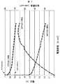
現在モバイル用に期待されている電源としては、PEFCよりも低温で使用可能であり、メタノールを直接燃料として使用する燃料電池である直接メタノール型燃料電池(DMFC)が期待されている。図1にPEFCとDMFCの電流電圧特性(I−V特性)とDMFCの電流電力特性(I−P特性)を示す。DMFCの特徴として開放電圧(以下、OCVと称す)の値は0.8V 以上ある状態がありPEFCと同程度である。しかし、現状報告されている単セルの電圧電流特性から考えると、図1に示すように実際の発電に使える領域は0.4V 以下となり、さらに最大電力点は0.2Vのあたりになっている。したがって、燃料電池という名前が同じであってもDMFCとPEFCの特性は非常に異なったものとなっており、PEFCの方式を直接DMFCに適用するのは難しく、専用の制御方式が必要となる。 As a power source currently expected for mobile use, a direct methanol fuel cell (DMFC) that can be used at a lower temperature than PEFC and that uses methanol as a direct fuel is expected. FIG. 1 shows current-voltage characteristics (IV characteristics) of PEFC and DMFC and current-power characteristics (IP characteristics) of DMFC. As a feature of the DMFC, the value of the open circuit voltage (hereinafter referred to as OCV) is 0.8 V or more, which is similar to that of the PEFC. However, considering the currently reported voltage-current characteristics of the single cell, as shown in FIG. 1, the area that can be used for actual power generation is 0.4 V or less, and the maximum power point is around 0.2 V. . Therefore, even if the names of fuel cells are the same, the characteristics of DMFC and PEFC are very different, and it is difficult to directly apply the PEFC method to DMFC, and a dedicated control method is required.
また、DMFCの特性は、温度や空気極の気体の流速(湿度)によっても大きく変化するうえ、何らかの原因(二酸化炭素や水のような反応に伴う生成物が詰まる等)で出力電力が急激に低下することもある。電源としては機器の必要とする電力を供給できることが最低限必要になるが、前記燃料電池の状態によっては必要な電力を供給できない場合が考えられるため、新たなシステムや制御方式が必要である。 In addition, the characteristics of the DMFC vary greatly depending on the temperature and the gas flow velocity (humidity) of the air electrode, and the output power suddenly increases for some reason (clogged products such as carbon dioxide and water). It may decrease. As a power source, it is necessary at a minimum to be able to supply the power required by the device. However, depending on the state of the fuel cell, it may be impossible to supply the required power, so a new system and control method are required.
また、必要電力を供給できない状態においては、特に最大電力点をはるかに超えて燃料電池から電流を引きすぎる状態が起こりえる。電流を引きすぎた場合は燃料電池セルの転極による燃料電池の劣化,燃料電池の温度上昇,2酸化炭素や水のような生成物の増加による状態悪化など問題となるそれぞれの状態に合わせた制御が必要になるが、高速な燃料電池の状態予測が非常に難しいうえに多くのセンサを搭載すると高コストになるという問題がある。 Further, in a state where the necessary power cannot be supplied, a state in which current is excessively drawn from the fuel cell may occur, far exceeding the maximum power point. If too much current is applied, the fuel cell will be deteriorated due to the reversal of the fuel cell, the temperature of the fuel cell will rise, and the state will deteriorate due to the increase of products such as carbon dioxide and water. Although control is required, there are problems that it is very difficult to predict the state of a high-speed fuel cell and that many sensors are expensive.
以上のような課題に対して本発明では、効果的にセンサを搭載して、燃料電池の状態に合わせた最大電力点追従制御が可能な電源装置及びその制御方法を提案することにある。 In order to solve the above-described problems, the present invention proposes a power supply apparatus capable of effectively mounting a sensor and performing maximum power point tracking control in accordance with the state of the fuel cell, and a control method therefor.
上記課題を実現するために、本発明では、入力電源として燃料電池を備えた電源装置において、前記電源装置の動作入力電圧範囲が前記燃料電池の最大電力点電圧以上となるよう通電量の制御を行う制御手段を備えたことを特徴とするものである。 In order to achieve the above object, according to the present invention, in a power supply device having a fuel cell as an input power supply, the energization amount is controlled so that the operation input voltage range of the power supply device is equal to or higher than the maximum power point voltage of the fuel cell. It is characterized by comprising control means for performing.
また、上記課題を実現するために、本発明では、入力電源として燃料電池を備えた電源装置において、負荷電力が前記燃料電池の最大電力より大きい場合でも、前記燃料電池の出力を最大電力までに制限する制御手段とを備えたことを特徴とするものである。 In order to achieve the above object, according to the present invention, in a power supply apparatus including a fuel cell as an input power supply, even when load power is larger than the maximum power of the fuel cell, the output of the fuel cell is reduced to the maximum power. And a control means for limiting.
また、上記課題を実現するために、本発明では、入力端から出力端への電圧変換機能を有した電源装置の制御方法において、入力端側に燃料電池、出力端側に蓄電手段を有し、出力端の要求電力が前記燃料電池の最大電力以下であるときには、出力端電圧の一定電圧制御を行うことを特徴とするものである。 In order to achieve the above object, according to the present invention, in a control method for a power supply device having a voltage conversion function from an input end to an output end, a fuel cell is provided on the input end side, and a storage means is provided on the output end side. When the required power at the output terminal is less than or equal to the maximum power of the fuel cell, a constant voltage control of the output terminal voltage is performed.
本発明によれば、機器への電力の安定供給と燃料電池の安定動作を実現する電源装置及びその制御方法を提供出来る。 ADVANTAGE OF THE INVENTION According to this invention, the power supply device which implement | achieves the stable supply of the electric power to an apparatus, and the stable operation | movement of a fuel cell, and its control method can be provided.
以下、本発明の制御用システムの構成およびその制御用ICの仕様およびその制御方法の詳細の実施例について、図を用いて説明する。 Hereinafter, the configuration of the control system of the present invention, the specification of the control IC, and a detailed example of the control method will be described with reference to the drawings.
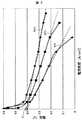
まず、本発明におけるDMFC特性の設定方法を述べる。図2に同一のDMFC単セルの温度変化による特性変化、図3に空気の流速の変化による特性変化を示す。ここで図2と図3に点線で示したような補助線を引くと、電流0での電圧が約0.41V でほぼ一致することが分かる。したがって、OCV付近で急速に電圧が上がる領域を除き、一般的に使用する領域におけるDMFCの等価回路の直流モデルは図4のように一定な設定電圧E(例えば0.41V )とDMFCの各状態により変化するDMFC内部抵抗Rで表すことができる。このようなモデルにおける出力電力Wは以下の式で表すことができる。(Ro:負荷抵抗) First, a DMFC characteristic setting method in the present invention will be described. FIG. 2 shows characteristic changes due to temperature changes of the same DMFC single cell, and FIG. 3 shows characteristic changes due to changes in air flow velocity. Here, when an auxiliary line as shown by a dotted line in FIG. 2 and FIG. 3 is drawn, it can be seen that the voltage at the current 0 is substantially equal at about 0.41V. Therefore, the DC model of the equivalent circuit of the DMFC in the region generally used except for the region where the voltage rapidly increases in the vicinity of the OCV is a constant set voltage E (eg, 0.41 V) and each state of the DMFC as shown in FIG. DMFC internal resistance R that varies depending on The output power W in such a model can be expressed by the following equation. (Ro: Load resistance)

上記式における出力電力Wが最大値になる条件は、R=Roであることから、DMFC出力電圧がE/2であることがDMFCの状態に関わらず一定な最大電力点の条件であることが分かった。 The condition for the maximum output power W in the above equation is R = Ro, so that the DMFC output voltage is E / 2 may be a constant maximum power point condition regardless of the state of the DMFC. I understood.
本発明を用いる場合は、あらかじめ使用するDMFC単セルの設定電圧Eを測定しておき、セル数倍することにより設計することになる。もちろん、PEFC等のような他のタイプの燃料電池に本設定方式を適用して設計することも可能である。 When the present invention is used, the design is performed by measuring the set voltage E of the DMFC single cell to be used in advance and multiplying the number of cells. Of course, the present setting method can be applied to other types of fuel cells such as PEFC.
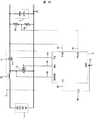
本発明の第1の実施例について図5を用いて説明する。 A first embodiment of the present invention will be described with reference to FIG.
本発明の構成は、大きく分けて燃料電池1と蓄電手段である電気2重層コンデンサ(以下、EDLCと称す)2と回路部3と制御IC4を備える。以下でそれぞれの詳細について述べる。 The configuration of the present invention broadly includes a
本実施例において、蓄電手段として使用するEDLC2は1セルあたりの耐圧が2.3V〜3.3V であるため、図5に示すように2セルで使用している場合は、従来Li電池1セルやNiMH2セルで駆動している機器に適用可能である(例えば携帯電話,PDA,デジタルスチルカメラ,マルチメディアプレイヤー等)。また、Li電池が複数セルになっているアプリケーションの場合(例えばノートPC等)では、Li電池2セル互換ではEDLC2を2〜4セル使用したり、Li電池3セル互換ではEDLC2を3〜5セル使用したりすれば良い。もちろん、EDLC2の代わりの蓄電手段として、Li電池等の2次電池を使用しても構わない。図5に示すように蓄電手段を設けることによって、燃料電池1から取り出せる最大電力よりも負荷の要求電力が大きい場合に不足分の電力をサポートすることができる。例えば燃料電池の一時的な状態悪化や負荷の要求電力が携帯電話等のようなパルス負荷の場合が考えられる。なお、パルス負荷が多いアプリケーションの場合は、EDLCのように放電特性に優れたものを使用することが効率改善のために望ましい。 In this embodiment, since the
本実施例では、燃料電池1にはDMFCを使うことを想定しているが、他の種類の燃料電池を使用しても構わない。また、図5では4セル分の燃料電池を使用しているが、回路部3の効率を考慮してセル数を増減させて構わない。 In this embodiment, it is assumed that a DMFC is used for the
回路部3はインダクタンスL32とNチャネルパワーMOS FET13とPチャネルパワーMOS FET14を用いた同期整流方式昇圧コンバータの構成になっている。このような昇圧コンバータでは、NチャネルパワーMOSFET13がONしたときのスイッチングサイクルで燃料電池1のエネルギーがインダクタンスLに貯えられ、PチャネルパワーMOSFET14がONしたときのスイッチングサイクルで燃料電池1のエネルギーと共にインダクタンスLに貯えられたエネルギーが電気2重層コンデンサ2へ充電するので、電気2重層コンデンサ2の充電電圧(蓄電電圧)は燃料電池1の出力電圧よりも高くなる(つまり、昇圧する)。 The
したがって、EDLC2の電圧は燃料電池1の電圧以上となる。もちろん、EDLC2以外に入出力に平滑用のコンデンサを設けてもよい。 Therefore, the voltage of the
制御IC4は、燃料電池電圧制限端子(Vlim)46,EDLC2電圧値取得用端子
(FBout)41,出力電圧値および電源取得用端子(Vout)42,スイッチ電流取得用端子(SENSE)45,インバータ回路24を介したPチャネルパワーMOS FET制御端子(TG)43,NチャネルパワーMOS FET制御端子(BG)44,GND端子(GND)40の合計7端子を少なくとも持つ。もちろん前記の他にICのON/
OFF端子やループ補償用の端子等を必要に応じて設けても良い。The
An OFF terminal, a terminal for loop compensation, and the like may be provided as necessary.
制御IC4の機能図の一例を図6に示す。 An example of a functional diagram of the
本構成の第1の特徴であるVlim の制御処理の動作を示す。本構成は昇圧型となっているため、微小な一定電流IlinがVout 端子42から定電流回路を通してVlim端子46に至る。Duty Limit回路26はVout−Vlin の電圧値に比例してDutyの制限を行う機能とVlin 端子の電圧が一定電圧以下となるとPWM LOGIC回路11を制御してPWMスイッチング動作を完全に停止する機能を備えている。本構成において前記機能を搭載することで、前記完全ストップする電圧をVstopとすると、Vstop=Ilin×Rin(50)+Vinとなることにより、Vinを燃料電池1の最大電力点電圧に設計することで確実に最大電力点までの電流範囲に制限することが可能になる。また、燃料電池1の電圧Vinが燃料切れや酸素不足などでVstopより低下した場合も安全にスイッチング動作を停止することが可能になる。 The operation of the Vlim control process, which is the first feature of this configuration, is shown. Since this configuration is a step-up type, a small constant current Ilin reaches the
次に、本構成の第2の特徴であるFBout端子41の処理動作を示す。本構成は一般的なDC/DCコンバータの出力電圧フィードバックと同様の構成になっており、Vref
120とFBout端子41が比較器22に入力され、その比較器の出力に応じてPWM LOGIC回路11は安定した出力電圧が得られるようにPWMスイッチング動作を制御する出力電力≪燃料電池最大電力の場合は、出力電圧一定制御となり、一般的なDC/
DCコンバータと特に変わらない。出力電力が燃料電池の最大電力に一定以上近づいた場合(出力電力<燃料電池最大電力)は、PWMのDutyの制限を行う制御を行う。出力電力≧燃料電池電力の場合は前記出力端に設けられたEDLC2等の蓄電手段によって不足分の出力がなされ、逐電手段の充電状態によって出力電圧も決まる。よってこの場合の制御はPWMのDuty制限の最大値で動作しつづけて垂下する状態となる。Next, the processing operation of the
120 and the
It is not particularly different from a DC converter. When the output power approaches the fuel cell maximum power above a certain level (output power <fuel cell maximum power), control is performed to limit the duty of PWM. In the case of output power ≧ fuel cell power, a shortage is output by the storage means such as
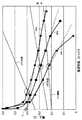
上記第1の特徴と第2の特徴をまとめた燃料電池出力特性と出力制限の関係を図7に示す。 FIG. 7 shows the relationship between the output characteristics of the fuel cell and the output limitation, in which the first feature and the second feature are summarized.
燃料電池出力により制限電圧に多少の差が出るが、各温度状態のDMFCの出力を示す電圧−電流密度に対して出力制限値のグラフを対比させた場合、本発明の実施例では各温度状態の燃料電池出力と出力制限値の交点以上の領域で電源装置は動作し、最大電力を超えることは無くなる。 Although there is a slight difference in the limit voltage depending on the output of the fuel cell, when the graph of the output limit value is compared with the voltage-current density indicating the output of the DMFC in each temperature state, in the embodiment of the present invention, each temperature state The power supply device operates in the region above the intersection of the fuel cell output and the output limit value, and does not exceed the maximum power.
更に、本構成の第3の特徴であるRin50の処理動作を示す。前記第1の特徴に述べたように、IlinとVstop の値から、Rin50の値を調整することにより設計者が燃料電池のセル数に応じて柔軟に制限値を設計することができる。また、図8に示すように、RinとしてNTCサーミスタ51を採用することによって、温度制限機能を追加することも可能である。このときの燃料電池出力特性と出力制限の関係を図9に示す。NTCサーミスタ51は低温時に高抵抗,高温時に低抵抗となる特性を示す。したがってNTCサーミスタ51をRinに適用することで低温時には制限されるVinをより低いところに設計でき、高温時には制限されるVinをより高いところに設計できるようになる。温度の上昇に伴い、燃料電池1から取り出す電流を絞る制御動作になるため、燃料電池1が例えば45℃を超えて使用者がやけどを起こす温度になるのを防ぐことができる。 Furthermore, the processing operation of Rin50, which is the third feature of this configuration, is shown. As described in the first feature, the designer can flexibly design the limit value according to the number of cells of the fuel cell by adjusting the value of Rin50 from the values of Ilin and Vstop. Further, as shown in FIG. 8, it is possible to add a temperature limiting function by employing an
また、本構成はDC/DCコンバータのPWM LOGIC11は通常制御動作において燃料電池電圧によりDuty制限を行うのが特徴であるため、既存のDC/DCコンバータICを使用して実現することが可能である。 Further, this configuration is characterized by the fact that the
従来の制御IC4の構成例を図10に示す。ソフトスタート端子(以下、SS端子と称す)49とGND端子40間にコンデンサC62を接続し、IC内部の定電流回路や高抵抗のスイッチによって前記コンデンサC62が徐々にチャージされることでSS端子49の電圧が一定以上に上昇するまでDuty制限やスイッチング電流制限などの出力電力制限を行うソフトスタート機能を備えた制御IC4の構成がある。このSS端子を上記構成と同様の入力端に抵抗Rin50を介して接続する構成にすることによっても、上記例と同様の効果を実現することが可能である。 A configuration example of a
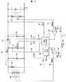
本発明の第2の実施例について図11を用いて説明する。特に言及しない限りにおいては前述に示した回路と同一の符号の構成部材は同様の構成及び効果を備えるものである。 A second embodiment of the present invention will be described with reference to FIG. Unless otherwise noted, constituent members having the same reference numerals as those in the circuit described above have the same configuration and effects.
本実施例は、燃料電池電圧制限用の端子と燃料電池温度制御用の端子が別になることで、それぞれ設計することが出来る構成となっている。本実施例は前述の第1の実施例と比べて、制御IC4に燃料電池温度制御用の端子(以下、TEMPと称す)48が追加されている。TEMP48に入力されるのは燃料電池1の温度情報であり、サーミスタや温度IC等のセンサ60により温度情報を取得する。また、制御IC4の内部構成も異なっており、Vout−Vlinと温度電圧−Vref2(29)の2つのフィードバック情報をDuty
Limit26に入力し、PWM LOGIC11の最大Duty制限を行う。制御動作としては、実施例1で例に挙げたものと同様に燃料電池電圧であるVinによる制限と燃料電池温度による制限の2つを兼ね備えるようになり、個々の状態に応じて動作するようになる。In this embodiment, the terminal for limiting the fuel cell voltage and the terminal for controlling the fuel cell temperature are separated from each other, so that each can be designed. In the present embodiment, a fuel cell temperature control terminal (hereinafter referred to as TEMP) 48 is added to the
Input to Limit 26 to limit the maximum duty of the
本実施例においては、Li電池6を蓄電手段として使用しているため、従来のLi電池の1セルやNiMHの2セルで駆動している機器に適用可能である(例えば携帯電話,
PDA,デジタルスチルカメラ,マルチメディアプレイヤー等)。もちろん、Li電池6の代わりの蓄電手段として、EDLCを使用しても構わない。In this embodiment, since the Li battery 6 is used as a power storage means, it can be applied to a device driven by one cell of a conventional Li battery or two cells of NiMH (for example, a mobile phone,
PDA, digital still camera, multimedia player, etc.). Of course, EDLC may be used as a power storage means instead of the Li battery 6.
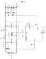
本発明の第3の実施例について図12を用いて説明する。特に言及しない限りにおいては前述に示した回路と同一の符号の構成部材は同様の構成及び効果を備えるものである。 A third embodiment of the present invention will be described with reference to FIG. Unless otherwise noted, constituent members having the same reference numerals as those in the circuit described above have the same configuration and effects.
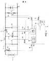
本実施例は第1,第2の実施例と比べて、回路部3を同期整流型ではなく、ショットキーバリアダイオード35を用いた昇圧チョッパ方式に変更した一例である。本構成にすることで、第1,第2の構成よりも出力端の電圧をより高くする場合に有効である。 The present embodiment is an example in which the
制御IC4の詳細について以下説明する。第1,第2の実施例と比較して、PチャネルパワーMOS FETの制御端子(TG)が不要となっている。また、制御IC4の内部の構成については、第1の実施例の構成や第2の実施例における構成のどちらを使用しても構わない。 Details of the
本実施例において、蓄電手段として使用するEDLC2は1セルあたりの耐圧が2.3V〜3.3V であるため、図12に示すように4セルで使用している場合は、従来Li電池2〜3セルで駆動している機器に適用可能である(例えばノートPC等)。もちろん、EDLC2の代わりの蓄電手段として、Li電池等の2次電池を使用しても構わない。 In this embodiment, since the
本発明の第4の実施例について図13を用いて説明する。特に言及しない限りにおいては前述に示した回路と同一の符号の構成部材は同様の構成及び効果を備えるものである。 A fourth embodiment of the present invention will be described with reference to FIG. Unless otherwise noted, constituent members having the same reference numerals as those in the circuit described above have the same configuration and effects.
本実施例は回路部3を降圧チョッパ方式に変更した一例である。本構成にすることで、燃料電池1の電圧よりも負荷電圧が低い場合に対応可能である。 The present embodiment is an example in which the
本実施例における制御IC4の詳細について以下で説明する。第1から第3の実施例と比較して、IC電源及びゲート駆動電圧としてVin端子47を備えている。降圧型であるため、Vlin47 は分圧により制限電圧を設計する方式となる。また、制御IC4の内部の構成については、第1の実施例の構成や第2の実施例における構成のどちらを使用しても構わない。 Details of the
本実施例において、蓄電手段として使用するEDLC2は1セルあたりの耐圧が2.3V〜3.3Vであるため、図13に示すように1セルで使用している場合は、1.8V の電圧等低電圧で駆動している機器に適用可能である。もちろん、EDLC2の代わりの蓄電手段として、Li電池やNi水素電池等の2次電池を使用しても構わない。 In this embodiment, since the
以上、4つの実施例を挙げたが、本発明の実施においては、当然に用途に応じて前記実施例のいくつかを組み合わせて使用しても構わない。 In the above, four examples have been described, but in the practice of the present invention, naturally, some of the examples may be used in combination depending on the application.
1…燃料電池、2…電気2重層コンデンサ、3…回路部、4…制御IC、11…PWM LOGIC、12…Vref Control LOGIC。
DESCRIPTION OF
Claims (11)
Translated fromJapanese前記電源装置の動作入力電圧範囲が前記燃料電池の最大電力点電圧以上となるよう通電量の制御を行う制御手段を備えたことを特徴とする電源装置。In a power supply device equipped with a fuel cell as an input power supply,
A power supply apparatus comprising control means for controlling an energization amount so that an operation input voltage range of the power supply apparatus is equal to or greater than a maximum power point voltage of the fuel cell.
前記電源装置の制御手段が出力電圧をフィードバックしてPWM制御を行う機能を有し、前記燃料電池電圧と前記制御手段の有する設定電圧との差が大きいほどPWM制御の最大Dutyが大きくなる制御機能を有することを特徴とする電源装置。In the power supply device according to claim 1,
A control function in which the control means of the power supply device performs a PWM control by feeding back an output voltage, and the maximum duty of the PWM control increases as the difference between the fuel cell voltage and the set voltage of the control means increases. A power supply device comprising:
前記電源装置の制御手段の有する設定電圧を抵抗によって構成し、抵抗値が大きいほど設定電圧を高く設定できることを特徴とする電源装置。In the power supply device of claim 2,
A power supply apparatus characterized in that the set voltage of the control means of the power supply apparatus is constituted by a resistor, and the larger the resistance value, the higher the set voltage can be set.
前記電源装置の制御手段は定電流回路を有し、該定電流回路の出力端は前記抵抗に接続され、前記定電流回路にかかる電圧が大きいほどPWM制御の最大Dutyを制限する制御を行うことを特徴とする電源装置。In the power supply device of claim 3,
The control means of the power supply device has a constant current circuit, and the output terminal of the constant current circuit is connected to the resistor, and performs control to limit the maximum duty of PWM control as the voltage applied to the constant current circuit increases. A power supply characterized by.
前記燃料電池の温度を検出する温度検出手段を備え、前記燃料電池の温度上昇に応じて前記設定電圧を上昇させる機能を持つことを特徴とする電源装置。In one power supply device of the said Claim 3 to 4,
A power supply apparatus comprising temperature detecting means for detecting the temperature of the fuel cell, and having a function of increasing the set voltage in response to a temperature increase of the fuel cell.
前記抵抗にNTCサーミスタを使用することにより、前記燃料電池の温度上昇に応じて前記設定電圧を上昇させる機能を備えたことを特徴とする電源装置。In the power supply device of claim 5,
A power supply apparatus comprising a function of increasing the set voltage in response to a temperature increase of the fuel cell by using an NTC thermistor for the resistor.
負荷電力が前記燃料電池の最大電力より大きい場合でも、前記燃料電池の出力を最大電力までに制限する制御手段とを備えたことを特徴とする電源装置。In a power supply device equipped with a fuel cell as an input power supply,
And a control means for limiting the output of the fuel cell to the maximum power even when the load power is larger than the maximum power of the fuel cell.
電力を蓄電する蓄電手段を備え、不足電力を前記蓄電手段から供給することを特徴とする電源装置。The power supply device according to claim 7, wherein
A power supply device comprising a power storage means for storing power, and supplying insufficient power from the power storage means.
入力端側に燃料電池、出力端側に蓄電手段を有し、出力端の要求電力が前記燃料電池の最大電力以下であるときには、出力端電圧の一定電圧制御を行うことを特徴とする電源装置の制御方法。In the control method of the power supply device having a voltage conversion function from the input end to the output end,
A power supply apparatus having a fuel cell on the input end side and a power storage means on the output end side, and performing constant voltage control of the output end voltage when the required power at the output end is less than or equal to the maximum power of the fuel cell Control method.
負荷電力が前記燃料電池の最大電力より大きい場合は、前記燃料電池の出力を最大電力までに制限する制御を行い、不足電力分を前記蓄電手段から供給することを特徴とする電源装置の制御方法。In the power supply device control method according to claim 9,
When the load power is larger than the maximum power of the fuel cell, a control method for limiting the output of the fuel cell to the maximum power and supplying the insufficient power from the power storage means is provided. .
出力端の要求電力が前記燃料電池の最大電力より大きく、負荷電力が前記燃料電池の最大電力より小さい場合は、前記燃料電池の出力を最大電力までに制限する制御を行い、負荷に対する余剰電力分を前記蓄電手段に充電することを特徴とする電源装置の制御方法。The method of controlling a power supply device according to any one of claims 10 to 9,
When the required power at the output end is larger than the maximum power of the fuel cell and the load power is smaller than the maximum power of the fuel cell, control is performed to limit the output of the fuel cell to the maximum power, and the surplus power to the load The power storage device is charged by charging the power storage means.
Priority Applications (3)
| Application Number | Priority Date | Filing Date | Title |
|---|---|---|---|
| JP2005286436AJP2007095617A (en) | 2005-09-30 | 2005-09-30 | Fuel cell device and control method thereof |
| CNA2006100086633ACN1941468A (en) | 2005-09-30 | 2006-02-20 | Power supply apparatus with fuel cell and method of controlling the same |
| US11/357,029US7883808B2 (en) | 2005-09-30 | 2006-02-21 | Power supply apparatus with fuel cell and method of controlling the same |
Applications Claiming Priority (1)
| Application Number | Priority Date | Filing Date | Title |
|---|---|---|---|
| JP2005286436AJP2007095617A (en) | 2005-09-30 | 2005-09-30 | Fuel cell device and control method thereof |
Publications (1)
| Publication Number | Publication Date |
|---|---|
| JP2007095617Atrue JP2007095617A (en) | 2007-04-12 |
Family
ID=37902284
Family Applications (1)
| Application Number | Title | Priority Date | Filing Date |
|---|---|---|---|
| JP2005286436APendingJP2007095617A (en) | 2005-09-30 | 2005-09-30 | Fuel cell device and control method thereof |
Country Status (3)
| Country | Link |
|---|---|
| US (1) | US7883808B2 (en) |
| JP (1) | JP2007095617A (en) |
| CN (1) | CN1941468A (en) |
Cited By (1)
| Publication number | Priority date | Publication date | Assignee | Title |
|---|---|---|---|---|
| US9065336B2 (en) | 2013-06-26 | 2015-06-23 | Industrial Technology Research Institute | Maximum power point tracking method and apparatus |
Families Citing this family (58)
| Publication number | Priority date | Publication date | Assignee | Title |
|---|---|---|---|---|
| US10693415B2 (en) | 2007-12-05 | 2020-06-23 | Solaredge Technologies Ltd. | Testing of a photovoltaic panel |
| US11881814B2 (en) | 2005-12-05 | 2024-01-23 | Solaredge Technologies Ltd. | Testing of a photovoltaic panel |
| US8816535B2 (en) | 2007-10-10 | 2014-08-26 | Solaredge Technologies, Ltd. | System and method for protection during inverter shutdown in distributed power installations |
| US8013472B2 (en) | 2006-12-06 | 2011-09-06 | Solaredge, Ltd. | Method for distributed power harvesting using DC power sources |
| US12316274B2 (en) | 2006-12-06 | 2025-05-27 | Solaredge Technologies Ltd. | Pairing of components in a direct current distributed power generation system |
| US11296650B2 (en) | 2006-12-06 | 2022-04-05 | Solaredge Technologies Ltd. | System and method for protection during inverter shutdown in distributed power installations |
| US8618692B2 (en) | 2007-12-04 | 2013-12-31 | Solaredge Technologies Ltd. | Distributed power system using direct current power sources |
| US11888387B2 (en) | 2006-12-06 | 2024-01-30 | Solaredge Technologies Ltd. | Safety mechanisms, wake up and shutdown methods in distributed power installations |
| US11309832B2 (en) | 2006-12-06 | 2022-04-19 | Solaredge Technologies Ltd. | Distributed power harvesting systems using DC power sources |
| US8473250B2 (en) | 2006-12-06 | 2013-06-25 | Solaredge, Ltd. | Monitoring of distributed power harvesting systems using DC power sources |
| US11735910B2 (en) | 2006-12-06 | 2023-08-22 | Solaredge Technologies Ltd. | Distributed power system using direct current power sources |
| US11569659B2 (en) | 2006-12-06 | 2023-01-31 | Solaredge Technologies Ltd. | Distributed power harvesting systems using DC power sources |
| US9088178B2 (en) | 2006-12-06 | 2015-07-21 | Solaredge Technologies Ltd | Distributed power harvesting systems using DC power sources |
| US9130401B2 (en) | 2006-12-06 | 2015-09-08 | Solaredge Technologies Ltd. | Distributed power harvesting systems using DC power sources |
| US8319471B2 (en) | 2006-12-06 | 2012-11-27 | Solaredge, Ltd. | Battery power delivery module |
| US9112379B2 (en) | 2006-12-06 | 2015-08-18 | Solaredge Technologies Ltd. | Pairing of components in a direct current distributed power generation system |
| US8947194B2 (en) | 2009-05-26 | 2015-02-03 | Solaredge Technologies Ltd. | Theft detection and prevention in a power generation system |
| US11687112B2 (en) | 2006-12-06 | 2023-06-27 | Solaredge Technologies Ltd. | Distributed power harvesting systems using DC power sources |
| US8963369B2 (en) | 2007-12-04 | 2015-02-24 | Solaredge Technologies Ltd. | Distributed power harvesting systems using DC power sources |
| US8319483B2 (en) | 2007-08-06 | 2012-11-27 | Solaredge Technologies Ltd. | Digital average input current control in power converter |
| US8384243B2 (en) | 2007-12-04 | 2013-02-26 | Solaredge Technologies Ltd. | Distributed power harvesting systems using DC power sources |
| US11855231B2 (en) | 2006-12-06 | 2023-12-26 | Solaredge Technologies Ltd. | Distributed power harvesting systems using DC power sources |
| JP4458126B2 (en)* | 2007-07-30 | 2010-04-28 | トヨタ自動車株式会社 | Fuel cell system and control method thereof |
| WO2009072076A2 (en) | 2007-12-05 | 2009-06-11 | Solaredge Technologies Ltd. | Current sensing on a mosfet |
| CN105244905B (en) | 2007-12-05 | 2019-05-21 | 太阳能安吉有限公司 | Release mechanism in distributed power device is waken up and method for closing |
| US9291696B2 (en) | 2007-12-05 | 2016-03-22 | Solaredge Technologies Ltd. | Photovoltaic system power tracking method |
| WO2009073867A1 (en) | 2007-12-05 | 2009-06-11 | Solaredge, Ltd. | Parallel connected inverters |
| US11264947B2 (en) | 2007-12-05 | 2022-03-01 | Solaredge Technologies Ltd. | Testing of a photovoltaic panel |
| US8111052B2 (en) | 2008-03-24 | 2012-02-07 | Solaredge Technologies Ltd. | Zero voltage switching |
| EP2294669B8 (en) | 2008-05-05 | 2016-12-07 | Solaredge Technologies Ltd. | Direct current power combiner |
| US12418177B2 (en) | 2009-10-24 | 2025-09-16 | Solaredge Technologies Ltd. | Distributed power system using direct current power sources |
| JP2011175963A (en)* | 2010-01-29 | 2011-09-08 | Sanyo Electric Co Ltd | Fuel cell system |
| US10673222B2 (en) | 2010-11-09 | 2020-06-02 | Solaredge Technologies Ltd. | Arc detection and prevention in a power generation system |
| US10673229B2 (en) | 2010-11-09 | 2020-06-02 | Solaredge Technologies Ltd. | Arc detection and prevention in a power generation system |
| GB2485527B (en) | 2010-11-09 | 2012-12-19 | Solaredge Technologies Ltd | Arc detection and prevention in a power generation system |
| US10230310B2 (en) | 2016-04-05 | 2019-03-12 | Solaredge Technologies Ltd | Safety switch for photovoltaic systems |
| GB2486408A (en) | 2010-12-09 | 2012-06-20 | Solaredge Technologies Ltd | Disconnection of a string carrying direct current |
| GB2483317B (en) | 2011-01-12 | 2012-08-22 | Solaredge Technologies Ltd | Serially connected inverters |
| US8570005B2 (en) | 2011-09-12 | 2013-10-29 | Solaredge Technologies Ltd. | Direct current link circuit |
| GB2498365A (en) | 2012-01-11 | 2013-07-17 | Solaredge Technologies Ltd | Photovoltaic module |
| US9853565B2 (en) | 2012-01-30 | 2017-12-26 | Solaredge Technologies Ltd. | Maximized power in a photovoltaic distributed power system |
| GB2498790A (en) | 2012-01-30 | 2013-07-31 | Solaredge Technologies Ltd | Maximising power in a photovoltaic distributed power system |
| GB2498791A (en) | 2012-01-30 | 2013-07-31 | Solaredge Technologies Ltd | Photovoltaic panel circuitry |
| GB2499991A (en) | 2012-03-05 | 2013-09-11 | Solaredge Technologies Ltd | DC link circuit for photovoltaic array |
| US10115841B2 (en) | 2012-06-04 | 2018-10-30 | Solaredge Technologies Ltd. | Integrated photovoltaic panel circuitry |
| US9548619B2 (en) | 2013-03-14 | 2017-01-17 | Solaredge Technologies Ltd. | Method and apparatus for storing and depleting energy |
| US9941813B2 (en) | 2013-03-14 | 2018-04-10 | Solaredge Technologies Ltd. | High frequency multi-level inverter |
| EP3506370B1 (en) | 2013-03-15 | 2023-12-20 | Solaredge Technologies Ltd. | Bypass mechanism |
| CN104078692B (en)* | 2013-11-27 | 2016-05-11 | 中科宇图天下科技有限公司 | Be applied to control device and the control method of microbiological fuel cell |
| US9318974B2 (en) | 2014-03-26 | 2016-04-19 | Solaredge Technologies Ltd. | Multi-level inverter with flying capacitor topology |
| CN106329898B (en)* | 2015-06-19 | 2021-09-14 | 康普技术有限责任公司 | Quick discharge circuit and discharge method for soft start circuit |
| US11177663B2 (en) | 2016-04-05 | 2021-11-16 | Solaredge Technologies Ltd. | Chain of power devices |
| US12057807B2 (en) | 2016-04-05 | 2024-08-06 | Solaredge Technologies Ltd. | Chain of power devices |
| US11018623B2 (en) | 2016-04-05 | 2021-05-25 | Solaredge Technologies Ltd. | Safety switch for photovoltaic systems |
| TWI610515B (en)* | 2017-06-02 | 2018-01-01 | 國立交通大學 | Fuel cell system |
| US11923779B2 (en)* | 2020-11-05 | 2024-03-05 | Astec International Limited | Control circuits and methods for regulating output voltages |
| CN114695928A (en)* | 2020-12-30 | 2022-07-01 | 丰田自动车株式会社 | Method for controlling output power of FCV fuel cell |
| CN114024005B (en)* | 2021-10-14 | 2023-07-04 | 同济大学 | Fuel cell system with rapid shutdown function and shutdown control method |
Citations (3)
| Publication number | Priority date | Publication date | Assignee | Title |
|---|---|---|---|---|
| WO2005008822A1 (en)* | 2003-07-16 | 2005-01-27 | Kabushiki Kaisha Toshiba | Liquid type fuel cell system and boosting unit thereof |
| JP2005056764A (en)* | 2003-08-06 | 2005-03-03 | Matsushita Electric Ind Co Ltd | Power supply device |
| JP2005184970A (en)* | 2003-12-18 | 2005-07-07 | Seiko Instruments Inc | Power generation system |
Family Cites Families (10)
| Publication number | Priority date | Publication date | Assignee | Title |
|---|---|---|---|---|
| CN2269691Y (en) | 1996-07-11 | 1997-12-03 | 黄甜仔 | Electronic ballast |
| US6657419B2 (en)* | 2001-11-19 | 2003-12-02 | Solarmate Corporation | Micro-solar insolation circuit |
| US6914412B2 (en)* | 2003-05-21 | 2005-07-05 | Nanoset, Llc | Assembly for utilizing residual battery energy |
| JP4085642B2 (en) | 2002-02-05 | 2008-05-14 | 株式会社エクォス・リサーチ | Fuel cell system |
| US6792793B2 (en)* | 2002-03-28 | 2004-09-21 | Ignition Lock International | Breath measurement instrument and breath alcohol interlock device incorporating same |
| JP3748434B2 (en)* | 2002-06-12 | 2006-02-22 | 株式会社東芝 | Direct methanol fuel cell system and fuel cartridge |
| CN2553414Y (en) | 2002-07-05 | 2003-05-28 | 北京通力环电气股份有限公司 | PWM type high frenquency switch power supply constant voltage/constant current controller |
| JP4271999B2 (en)* | 2003-06-20 | 2009-06-03 | 株式会社ジェイエスピー | Styrenic resin foam containing aluminum powder |
| CN1627221A (en) | 2003-12-12 | 2005-06-15 | 大连新源动力股份有限公司 | A fuel cell output voltage adjustment method and the adjustment device used |
| US7381490B2 (en)* | 2004-03-25 | 2008-06-03 | Matsushita Electric Industrial Co., Ltd. | Power system for fuel cell, electronic equipment and electric power feeding method |
- 2005
- 2005-09-30JPJP2005286436Apatent/JP2007095617A/enactivePending
- 2006
- 2006-02-20CNCNA2006100086633Apatent/CN1941468A/enactivePending
- 2006-02-21USUS11/357,029patent/US7883808B2/ennot_activeExpired - Fee Related
Patent Citations (3)
| Publication number | Priority date | Publication date | Assignee | Title |
|---|---|---|---|---|
| WO2005008822A1 (en)* | 2003-07-16 | 2005-01-27 | Kabushiki Kaisha Toshiba | Liquid type fuel cell system and boosting unit thereof |
| JP2005056764A (en)* | 2003-08-06 | 2005-03-03 | Matsushita Electric Ind Co Ltd | Power supply device |
| JP2005184970A (en)* | 2003-12-18 | 2005-07-07 | Seiko Instruments Inc | Power generation system |
Cited By (1)
| Publication number | Priority date | Publication date | Assignee | Title |
|---|---|---|---|---|
| US9065336B2 (en) | 2013-06-26 | 2015-06-23 | Industrial Technology Research Institute | Maximum power point tracking method and apparatus |
Also Published As
| Publication number | Publication date |
|---|---|
| US20070077468A1 (en) | 2007-04-05 |
| US7883808B2 (en) | 2011-02-08 |
| CN1941468A (en) | 2007-04-04 |
Similar Documents
| Publication | Publication Date | Title |
|---|---|---|
| JP2007095617A (en) | Fuel cell device and control method thereof | |
| JP4898343B2 (en) | Power supply | |
| CN1893216B (en) | Electronic equipment and battery components and load devices used in the electronic equipment | |
| US20060222916A1 (en) | Mehotd for determining a maximum power point voltage of a fuel cell, as well as fuel cell control system and power controller used in the fuel cell control system | |
| CN1738087B (en) | Power supply device and control method thereof | |
| CN102498635B (en) | Hybrid power supply system | |
| US20050112420A1 (en) | Power supply device | |
| US20080160370A1 (en) | Adaptive Current Controller for a Fuel-Cell System | |
| JP2009232665A (en) | Power supply device and power supply control method | |
| JP2008199804A (en) | POWER SUPPLY CIRCUIT FOR POWER SUPPLYING CHARGE CONTROL CIRCUIT, CHARGING DEVICE HAVING THE POWER SOURCE CIRCUIT, AND METHOD FOR POWER SUPPLYING CHARGE CONTROL CIRCUIT | |
| KR20120008353A (en) | Fuel cell system and power management method thereof | |
| CA2663708A1 (en) | Fuel cell system | |
| JP2007280741A (en) | Fuel cell device | |
| JP5131805B2 (en) | Fuel cell system | |
| JP5509655B2 (en) | Fuel cell system and vehicle equipped with the same | |
| JP2007265840A (en) | Fuel cell system | |
| KR20150088318A (en) | Thin film microbattery charge and output control | |
| Monteiro et al. | Efficient supercapacitor energy usage in mobile phones | |
| US7336053B2 (en) | Battery-powered electronic equipment with charge control circuit | |
| JP4971773B2 (en) | FUEL CELL POWER SUPPLY DEVICE AND FUEL CELL CONTROL METHOD | |
| JP2008004379A (en) | Fuel cell system | |
| JP4323405B2 (en) | Semiconductor device for power supply control | |
| JP4990573B2 (en) | Fuel cell system | |
| JP2011211812A (en) | Power unit | |
| JP2007299532A (en) | Fuel cell system |
Legal Events
| Date | Code | Title | Description |
|---|---|---|---|
| A621 | Written request for application examination | Free format text:JAPANESE INTERMEDIATE CODE: A621 Effective date:20070706 | |
| A977 | Report on retrieval | Free format text:JAPANESE INTERMEDIATE CODE: A971007 Effective date:20110104 | |
| A131 | Notification of reasons for refusal | Free format text:JAPANESE INTERMEDIATE CODE: A131 Effective date:20110301 | |
| A02 | Decision of refusal | Free format text:JAPANESE INTERMEDIATE CODE: A02 Effective date:20111122 |