JP2007094928A - Communication module, communications device, output information control method, and output information control program - Google Patents
Communication module, communications device, output information control method, and output information control programDownload PDFInfo
- Publication number
- JP2007094928A JP2007094928AJP2005285923AJP2005285923AJP2007094928AJP 2007094928 AJP2007094928 AJP 2007094928AJP 2005285923 AJP2005285923 AJP 2005285923AJP 2005285923 AJP2005285923 AJP 2005285923AJP 2007094928 AJP2007094928 AJP 2007094928A
- Authority
- JP
- Japan
- Prior art keywords
- information
- output
- tag
- data
- input
- Prior art date
- Legal status (The legal status is an assumption and is not a legal conclusion. Google has not performed a legal analysis and makes no representation as to the accuracy of the status listed.)
- Pending
Links
- 230000006854communicationEffects0.000titleclaimsabstractdescription93
- 238000004891communicationMethods0.000titleclaimsabstractdescription86
- 238000000034methodMethods0.000titleclaimsdescription37
- 238000012545processingMethods0.000claimsdescription27
- 230000006870functionEffects0.000claimsdescription13
- 238000012905input functionMethods0.000claimsdescription4
- 230000005540biological transmissionEffects0.000description21
- 238000013500data storageMethods0.000description12
- WVMLRRRARMANTD-FHLIZLRMSA-Nram-316Chemical compoundC1=CCC[C@@]2(O)[C@H]3CC4=CC=C(OC)C(O)=C4[C@]21CCN3CWVMLRRRARMANTD-FHLIZLRMSA-N0.000description11
- 230000004044responseEffects0.000description9
- 238000010586diagramMethods0.000description8
- 230000005236sound signalEffects0.000description3
- 239000004065semiconductorSubstances0.000description2
- 238000012546transferMethods0.000description2
- 238000004364calculation methodMethods0.000description1
- 238000001514detection methodMethods0.000description1
- 230000005674electromagnetic inductionEffects0.000description1
- 239000004973liquid crystal related substanceSubstances0.000description1
- 230000003287optical effectEffects0.000description1
- SVKQEADHBGJMJB-FHLIZLRMSA-Nram-317Chemical compoundC1CCC[C@@]2(O)[C@H]3CC4=CC=C(OC)C(O)=C4[C@]21CCN3CSVKQEADHBGJMJB-FHLIZLRMSA-N0.000description1
Images


Landscapes
- Mobile Radio Communication Systems (AREA)
- Management, Administration, Business Operations System, And Electronic Commerce (AREA)
Abstract
Description
Translated fromJapanese本発明は、非接触通信システムに適用される通信モジュール、通信装置、出力情報制御方法、及び、出力情報制御プログラムに関する。 The present invention relates to a communication module, a communication device, an output information control method, and an output information control program applied to a contactless communication system.
従来、商品に関する情報を提供する手段として無線ICタグ(通信モジュール)が利用されるようになってきている。 Conventionally, wireless IC tags (communication modules) have been used as means for providing information about products.
例えば、特許文献1には、読み書き可能なICチップをレシートに配置し、商品の購入やサービスの提供に伴って行われた金銭の授受についての情報を印字するとともにICチップに書き込み、消費者に提供するレジスタが記載されている。 For example, in
また、特許文献2には、個々の商品を特定するための識別記号が入力された無線ICタグを個々の商品に取り付けておき、購入者が無線ICタグ読取装置を用いて個々の商品に取り付けられている無線ICタグからその商品に対応する識別記号を読み取ると、ネットワークを介して商品情報データベースにアクセスし、その識別記号に対応する商品の商品情報を提供するシステムが記載されている。
しかしながら、特許文献1においては、会計時に商品の購入やサービスの提供に伴って行われた金銭の授受についての情報をICチップに書き込むため、ICチップからは、商品の購入後に商品の購入やサービスの提供に伴って行われた金銭の授受についての情報を得ることしかできない。また、会計時に情報をICチップに書き込むため、そのための時間を要することとなる。 However, in
また、特許文献2においては、無線ICタグの識別記号をもとに、ネットワークを介してデータベースにアクセスし、ネットワークを介して商品情報を提供するので、無線ICタグから直接情報を提供することができない。即ち、ネットワーク接続手段がなければ商品情報等の提供を受けることができない。また、商品の購入前には商品情報を、商品の購入後にはサービス情報をといったように、閲覧する情報を切り換えることができない。 Further, in
本発明の課題は、非接触通信システムに利用されるICタグのような通信モジュールに記憶される情報について、出力の可否を容易に変更することである。 An object of the present invention is to easily change whether to output information stored in a communication module such as an IC tag used in a contactless communication system.
上記課題を解決するため、請求項1に記載の発明の通信モジュールは、
複数種類の情報を記憶する記憶手段と、
この記憶手段に記憶されている複数種類の情報を非接触通信システムを利用して外部機器へ出力する出力手段と、
前記記憶手段に記憶された複数種類の情報のうち出力すべき情報を指示する制御情報を、前記非接触通信システムにより入力する第1の入力手段と、
この第1の入力手段によって入力された制御情報に基づいて、前記出力手段によって出力すべき情報を制御する出力制御手段と、
を備えたことを特徴としている。In order to solve the above-described problem, a communication module according to the first aspect of the present invention provides:
Storage means for storing a plurality of types of information;
An output means for outputting a plurality of types of information stored in the storage means to an external device using a non-contact communication system;
First input means for inputting control information indicating information to be output among a plurality of types of information stored in the storage means by the contactless communication system;
Output control means for controlling information to be output by the output means based on the control information input by the first input means;
It is characterized by having.
請求項2に記載の発明は、請求項1に記載の発明において、
前記複数種類の情報は夫々1以上の項目を含んでおり、
前記制御情報は、何れの項目を外部機器へ出力するかを指示する情報を含むことを特徴としている。The invention according to
Each of the plurality of types of information includes one or more items,
The control information includes information instructing which item to output to an external device.
請求項3に記載の発明は、請求項1又は2に記載の発明において、
前記記憶手段に新たに記憶させるべき情報を、前記非接触通信システムにより入力する第2の入力手段と、
この第2の入力手段によって入力された情報を前記記憶手段に記憶させる記憶制御手段と、
をさらに備えたことを特徴としている。The invention according to
Second input means for inputting information to be newly stored in the storage means by the non-contact communication system;
Storage control means for storing in the storage means information input by the second input means;
Is further provided.
請求項4に記載の発明は、請求項1乃至3の何れか一項に記載の発明において、
前記記憶手段に記憶され、前記出力手段により出力される情報とは、前記非接触通信システムにより取得した外部機器で用いられる通信処理に関わる情報であることを特徴としている。The invention according to
The information stored in the storage means and output by the output means is information related to communication processing used in an external device acquired by the non-contact communication system.
請求項5に記載の発明は、
非接触通信システムに適用される通信装置であって、
通信対象となる通信モジュールに記憶された複数種類の情報のうち出力すべき情報を指示する制御情報を、当該非接触通信システムにより入力する入力手段を備えたことを特徴としている。The invention described in claim 5
A communication device applied to a non-contact communication system,
It is characterized by comprising an input means for inputting control information for instructing information to be output among a plurality of types of information stored in a communication module to be communicated by the non-contact communication system.
請求項6に記載の発明の出力情報制御方法は、
予めメモリに記憶されている複数種類の情報を非接触通信システムを利用して外部機器へ出力する出力ステップと、
前記メモリに記憶された複数種類の情報のうち出力すべき情報を指示する制御情報を、前記非接触通信システムにより入力する入力ステップと、
この入力ステップにて入力された制御情報に基づいて、前記出力ステップにて出力すべき情報を制御する出力制御ステップと、
を含むことを特徴としている。The output information control method of the invention described in claim 6 is:
An output step of outputting a plurality of types of information stored in advance in a memory to an external device using a non-contact communication system;
An input step of inputting control information indicating information to be output among a plurality of types of information stored in the memory by the contactless communication system;
Based on the control information input in this input step, an output control step for controlling information to be output in the output step;
It is characterized by including.
請求項7に記載の発明は、
コンピュータに、
複数種類の情報をメモリに記憶させる記憶機能と、
この記憶機能にて記憶されている複数種類の情報を非接触通信システムを利用して外部機器へ出力する出力機能と、
前記記憶機能にて記憶された複数種類の情報のうち出力すべき情報を指示する制御情報を、前記非接触通信システムにより入力する入力機能と、
この入力機能にて入力された制御情報に基づいて、前記出力機能にて出力すべき情報を制御する出力制御機能と、
を実現させるための出力情報制御プログラムであることを特徴としている。The invention described in claim 7
On the computer,
A storage function for storing multiple types of information in a memory;
An output function for outputting a plurality of types of information stored in the storage function to an external device using a non-contact communication system; and
An input function for inputting control information indicating information to be output among a plurality of types of information stored in the storage function by the contactless communication system;
Based on the control information input by the input function, an output control function for controlling information to be output by the output function;
It is an output information control program for realizing the above.
請求項1、5、6、及び7に記載の発明によれば、非接触通信システムを介して、記憶手段に記憶された複数種類の情報のうち出力すべき情報を指示する制御情報を入力し、この入力された制御情報に基づいて、出力すべき情報を制御する。
従って、非接触通信システムによって出力される情報の出力の可否を容易に変更することが可能となる。According to the first, fifth, sixth and seventh aspects of the present invention, control information indicating information to be output among a plurality of types of information stored in the storage means is input via the non-contact communication system. The information to be output is controlled based on the input control information.
Therefore, it is possible to easily change whether to output information output by the non-contact communication system.
請求項2に記載の発明によれば、請求項1に記載の発明に加え、複数種類の情報の夫々の項目について、出力される情報の出力の可否を容易に変更することが可能となる。 According to the invention described in
請求項3に記載の発明によれば、請求項1または2に記載の発明に加え、新たに記憶させるべき情報を、非接触通信システムにより入力して、記憶させることができるので、新規の情報を非接触通信システムを利用して書き込むことができる。 According to the invention described in
請求項4に記載の発明によれば、請求項1乃至3の何れか一項に記載の発明に加え、出力される情報が、外部機器で用いられる通信処理に関わる情報であるので、外部機器の通信処理を制御する情報についても出力の可否を容易に変更することが可能となる。 According to the invention described in
以下、図を参照して、本発明の実施形態を詳細に説明する。
まず、構成を説明する。Hereinafter, embodiments of the present invention will be described in detail with reference to the drawings.
First, the configuration will be described.
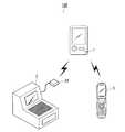
図1は、商品情報提供システム100の全体構成を示す概念図である。図1に示すように、商品情報提供システム100は、ICタグ1と、金銭登録機2と、携帯端末3とを備えて構成されている。ICタグ1は、店舗内の各商品に取り付けられた通信モジュールである。金銭登録機2は、ICタグ1に対応するリーダライタ24を有しており、このリーダライタ24を介して非接触状態でICタグ1と無線により情報の送受信(非接触通信)を行い、ICタグ1に対して情報の書き込み及び読み出しを行う。携帯端末3は、後述するようにICタグ1に対応するリーダを内蔵しており、このリーダを介して非接触状態でICタグ1と無線により情報の送受信を行い、ICタグ1からの情報の読み出しを行い、読み出した情報を表示部に表示する。 FIG. 1 is a conceptual diagram showing the overall configuration of the product
以下、商品情報提供システム100を構成する各装置について説明する。 Hereinafter, each apparatus which comprises the merchandise
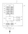
ICタグ1は、図2に示すように、送受信部12、電源部13、CPU14、ROM15、RAM16、メモリ17等を備えた1つ以上のICチップで構成される非接触ICチップ10と、アンテナ11等と、を備えて構成されている。 As shown in FIG. 2, the
アンテナ11は、コイルアンテナを備え、ICタグ1に対応する外部のリーダ又はリーダライタ、例えば、金銭登録機2のリーダライタ24又は携帯端末3に備えられたリーダ309からの電波信号を受信する。また、アンテナ11は、送受信部12から入力された信号をリーダ又はリーダライタに送信する。なお、ICタグ1に適用される非接触通信方式(電磁誘導方式、マイクロ波方式等)は特に限定されない。 The
送受信部12は、アンテナ11を介してICタグ1に対応するリーダ又はリーダライタから受信した信号を復調し、復調により得られた情報をCPU14に出力する。また、送受信部12は、CPU14によりメモリ17から読み出された情報を変調増幅し、アンテナ11に出力する。 The transmission /
電源部13は、アンテナ11を介してリーダ又はリーダライタから受信した電波信号を電力に変換し、ICタグ1の各部への電源供給を行う。 The
CPU(Central Processing Unit)14は、ROM(Read Only Memory)15に記憶されている制御プログラムを読み出し、RAM(Random Access Memory)16内に形成されたワークエリアに展開し、該制御プログラムに従ってICタグ1の各装置、各部を制御し、外部機器との通信の確立、外部機器から出力要求された情報の読み出し及び送信、外部機器から書き込み要求された受信情報の書き込みを行う。例えば、CPU14は、金銭登録機2からの接続要求が受信されると、通信を確立し、金銭登録機2からの商品コード及び購入後データの送信要求に従って、メモリ17から商品コード及び購入後データを読み出して金銭登録機2に送信する。また、CPU14は、金銭登録機2から購入前データ又は購入後データが受信されると、受信された情報を所定の購入前データ領域171又は購入後データ領域172に書き込んで記憶させる。また、金銭登録機2から制御データ(制御情報)が受信されると、受信された情報を制御データ領域173に書き込んで記憶させる。更に、CPU14は、携帯端末3のリーダからの接続要求が受信されると、通信を確立し、金銭登録機2からの出力要求に従って、制御データにより指示された情報を読み出して携帯端末3に出力する出力制御を行う。 A CPU (Central Processing Unit) 14 reads out a control program stored in a ROM (Read Only Memory) 15, expands it in a work area formed in a RAM (Random Access Memory) 16, and an IC tag according to the
ROM15は、ICタグ1に対応する制御プログラム、各種処理プログラム及びこれらのプログラムで利用する各種情報等を予め記憶する。
RAM16は、CPU14により実行される各種プログラム、各処理において処理中の情報、処理結果などを一時的に格納するワークエリアを形成する。The
The
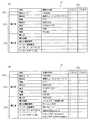
メモリ17は、電気的に内容を消去したり書き換えたりすることができる、半導体の不揮発性メモリ等で構成され、CPU14から書き込まれた各種情報を記憶する。図3(a)は、メモリ17の記憶領域の詳細を示す図である。同図において、メモリ17は、購入前データ領域171、購入後データ領域172、制御データ領域173、および、商品コード記憶領域174を有し、CPU14からの書き込み動作に応じて、金銭登録機2のリーダライタ24から送信された購入前データを購入前データ領域171に、また、購入後データを購入後データ領域172に、さらに、制御データを制御データ領域173に記憶する。 The
購入前データ記憶領域171に記憶される購入前データは、図3(a)に示すように商品名「携帯ミュージックプレーヤーA」、型番「2115」、発売日「2005/3/25」、スペックとして、表示「12文字×5桁」、容量「10GB」、価格「¥19,800」等の情報より構成される。
一方、購入後データ記憶領域172の購入後データは、主にICタグ1が取り付けられた商品に関する購入後のサービス情報が含まれ、購入日、購買店舗、アフターサービスの問い合わせ先として、購入店舗電話番号、メーカー電話番号、メーカーメールアドレス、メーカーサポートURL(Uniform Resource Locator)等の情報より構成される。
制御データ記憶領域173の制御データは、外部のリーダ(例えば、携帯端末3のリーダ309等)からのデータ送信要求があった場合に、メモリ17に記憶されている購入前データ及び購入後データのうち何れを出力すべきかを指示する情報を含む。この制御データは、フラグ情報(フラグA、フラグB)により構成されており、フラグAに「1」がセットされている項目については、外部のリーダがかざされることにより読み出され、出力される。As shown in FIG. 3A, the pre-purchase data stored in the pre-purchase
On the other hand, the post-purchase data in the post-purchase
The control data stored in the control
本実施の形態においては、金銭登録機2のリーダライタ24又はその他店舗のPC等が備えるリーダライタにより、店舗内の各商品に取り付けられたICタグ1におけるメモリ17の購入前データ記憶領域171、制御データ記憶領域173、商品コード記憶領域174の各領域には、予め各項目に対応する情報の内容が記憶されているものとする。 In the present embodiment, the pre-purchase
金銭登録機2は、図4に示すように、CPU21、入力部22、表示部23、リーダライタ24、音声出力部25、RAM26、記憶部27、印刷装置28、ドロア29等を備えて構成されている。 As shown in FIG. 4, the
CPU21は、記憶部27に記憶されているシステムプログラムを読み出し、RAM26内に形成されたワークエリアに展開し、該システムプログラムに従って金銭登録機2の各装置、各部を制御する。また、CPU21は、記憶部27に記憶されている会計時処理プログラムを始めとする各種処理プログラムを読み出してワークエリアに展開し、後述する会計時処理における金銭登録機2側の処理を始めとする各種処理を実行する。 CPU21 reads the system program memorize | stored in the memory |
入力部22は、モードキー、テンキー、ファンクションキー、担当者キー等を備え、各キー操作に応じた操作信号をCPU21に出力する。 The
表示部23は、LCD(Liquid Crystal Display)等により構成され、CPU21から入力される各種指示に従って各種演算結果等の表示を行う。 The
リーダライタ24は、アンテナ、送受信部、リーダライタ制御部、インターフェース(何れも図示せず)等を備えて構成され、所定のプロトコルに基づきICタグ1との通信を確立してデータ送受信を行い、ICタグ1へのデータの書き込み及び読み出しを行う。 The reader /
音声出力部25は、CPU21からの指示に応じて報知音を出力する。 The
RAM26は、CPU21により実行されるシステムプログラム、各種処理プログラム、各処理において処理中のデータ、処理結果などを一時的に格納するワークエリアを形成する。 The
記憶部27は、磁気的、光学的記録媒体、若しくは半導体等の不揮発性メモリで構成されており、金銭登録機2に対応するシステムプログラム、会計時処理プログラムをはじめとする各種処理プログラム、これらのプログラムで利用する各種情報等を予め記憶する。 The
また、記憶部27は、ICタグ情報ファイル271及び売上データファイル272を記憶している。
図5は、ICタグ情報ファイル271の情報格納例を示す図であるが、基本的に図3(a)にて示された項目、および、情報の内容に沿っている。詳細には、図5に示すように、ICタグ情報ファイル271は、店舗内の各商品の商品コードと、その商品に関する購入前データ及び購入後データとを対応付けて記憶する。 売上データファイル272は、各商品の商品コードに対応付けて、その単価、売上個数、売上金額等を記憶する。The
FIG. 5 is a diagram showing an example of information storage in the IC
なお、ICタグ情報ファイル271の内容に変更や追加があった場合、入力部22を介して変更又は追加すべき情報が入力されると、ICタグ情報ファイル271の内容が入力された情報に更新される。或いは、金銭登録機2を通信ネットワークを介してPC(Personal Computer)等のサーバに接続可能な構成とし、情報の追加や変更はPC等のサーバにおいて行い、サーバにおいて情報の変更及び追加が行われる毎に、自動的にICタグ情報ファイル271の内容が最新のものに書き換えられるようにしてもよい。 When the contents of the IC tag information file 271 are changed or added, when the information to be changed or added is input via the
印刷装置28は、例えば、サーマルプリンタであり、レシート用、ジャーナル用(商品登録内容の記録用)のロール紙を有し、CPU21から入力される指示に従って、各ロール紙に対して各種売上データ、小計データ等の金額データを売上明細として印刷する。
ドロア29は、現金を収納する引出しである。The
The
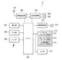
携帯端末3は、図6に示すように、アンテナ301、無線通信部302、音声処理部303、受話スピーカ304、送話マイク305、CPU306、表示部307、入力部308、リーダ309、鳴音駆動部310、スピーカ311、メールプログラム領域313、Webブラウザプログラム領域314、非接触通信プログラム領域315を含むプログラムメモリ312、RAM316を備える。 As shown in FIG. 6, the
無線通信部302は、アンテナ301を介して図示しない無線基地局から受信した無線通信信号を復調処理し、復調したベースバンド信号(デジタル信号)から通信制御データ、通信データ、パケットデータ等を取得する。この通信データは、音声処理部303を介してアナログ音声信号に変換され受話スピーカ304に出力される。また、前記パケットデータは、CPU306に読み込まれ、一時記憶メモリであるRAM316に出力される。一方、送話マイク305より入力されたアナログ音声信号が音声処理部303で所定のアルゴリズムによりコード化され通信データとして無線通信部302に出力されると、無線通信部302は、通信データに通信制御データ等を付加したベースバンド信号(デジタル信号)を変調処理し、アンテナ301を介して図示しない無線基地局に送信する。 The
音声処理部303は、無線通信部302を介して入力された通信データを音声データにデコードし、さらにアナログ音声信号に変換したのち、受話スピーカ304を介して出力する一方、送話マイク305を介して入力されたアナログ音声信号をコード化処理して通信データに変換して無線処理部302へ出力する。 The
CPU306は、プログラムメモリ312に記憶されている各種プログラムのうちの指定されたプログラムを読み出し、RAM316のワークエリアに展開し、上記プログラムとの協働によって各種処理を実行し、その処理結果をRAM316の所定の領域に格納するとともに、表示部307に表示させる。 The
表示部307は、各種プログラムの処理により得られた表示データを表示する。
入力部308はオンフックキー、オフフックキー、テンキー、センターキー、カーソルキー等を備え、CPU306はこれらのキー操作を検出することにより、各回路部を制御する。The
The
リーダ309は、非接触通信プログラムが起動することによりICタグ1からの情報を読み取る。CPU306は、その読み取り結果を、一時記憶メモリであるRAM316に記憶させるとともに、表示部307に表示する。 The
鳴音駆動部310は、携帯端末3の着信時等にCPU306からの鳴音指示により鳴音信号をスピーカ311に出力し、鳴音によりユーザに通話やメールの着信等を報知する。 The sounding
プログラムメモリ312は、メールプログラム領域313、Webブラウザプログラム領域314、非接触通信プログラム領域315等を含む。
RAM316は、CPU306により実行される各種プログラム及びこれらプログラムに係わるデータを一時的に記憶するワークエリアを形成する。The
The
次に、本実施形態の動作について説明する。
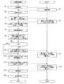
図7は、金銭登録機2のCPU21により実行される会計時処理の動作及び会計時処理において金銭登録機2からの接続要求に応じて実行されるICタグ1の動作を示すフロー図である。会計時処理は、金銭登録機2の操作者により入力部22の所定キーが押下された際に開始される。なお、ここでいうICタグ1は、会計時に顧客により金銭登録機2のところへ持ち運ばれた商品に取り付けられたものを指す。Next, the operation of this embodiment will be described.
FIG. 7 is a flowchart showing the operation of the accounting process executed by the
まず、金銭登録機2において、操作者がICタグ1をリーダライタ24にかざすと、リーダライタ24によりICタグ1への接続要求が行われる(ステップS1)。ICタグ1において、リーダライタ24からの接続要求が受信されると、リーダライタ24に対して接続応答が送信され、通信の確立が行われる(ステップS2)。ICタグ1との通信接続が確立すると、金銭登録機2においては、音声出力部25により通信開始を報知するための報知音が出力される(ステップS3)。 First, in the
次いで、リーダライタ24を介して、ICタグ1に対し商品コード及び購入後データの送信要求が行われる(ステップS4)。ICタグ1においては、この送信要求が受信されると、メモリ17の商品コード領域174から商品コードが、購入後データ領域172から購入後データが読み出され、リーダライタ24に対して送信される(ステップS5)。 Next, a transmission request for a product code and post-purchase data is made to the
リーダライタ24を介して、商品コード及び購入後データが受信されると、受信された購入後データがRAM26に一時的に記憶される(ステップS6)。また、受信された商品コードにより商品登録処理が行われ、売上データファイル272が更新されるとともに、商品コード、金額等が印刷装置28によりレシート及びジャーナルに印刷される(ステップS7)。 When the product code and the post-purchase data are received via the reader /
商品登録処理が終了すると、ICタグ1から受信された商品コードに対応する購入後データがICタグ情報ファイル271から読み出され、ICタグ1から受信された購入後データとの比較が行われる(ステップS8)。 比較の結果、データが一致すると判断された場合(ステップS9;YES)、処理はステップS12に移行する。比較の結果、データが一致しないと判断された場合(ステップS9;NO)、リーダライタ24を介して、ICタグ情報ファイル271から読み出された購入後データがICタグ1に送信され、当該購入後データの書き込み要求が行われる(ステップS10)。 When the product registration process is completed, the post-purchase data corresponding to the product code received from the
ICタグ1においては、新たな購入後データが受信されると、受信された購入後データがメモリ17の購入後データ領域172に書き込まれ、記憶される(ステップS11)。 In the
ステップS12においては、表示部23に、ICタグ1から外部に出力すべきデータの指定を促す表示が表示され、入力部22により、出力すべきデータの指定情報の入力が行われると(ステップS12)、入力された指定情報に対応する制御データがリーダライタ24を介してICタグ1に送信され、当該制御データの書き込み要求が行われる(ステップS13)。ICタグ1から外部に出力すべきデータの指定情報の入力は、例えば、各制御データとその制御データが指示する内容とを対応付けて表示部23に表示し、操作者に購入者の要望に応じた制御データをテンキーにより入力させることにより行うことができる。また、各制御データが指示する内容のみを表示部23に表示し、表示された内容の中から購入者の要望に応じた内容をカーソルキー等により操作者に選択させるようにしてもよい。ICタグ1においては、制御データが受信されると、受信された制御データがメモリ17の制御データ領域173に書き込まれる(ステップS14)。 In step S12, a display for prompting designation of data to be output from the
ここで、例えば、入力部22から、ICタグ1が購入後データを出力するように指示する制御データ(フラグAをセットする情報)が入力されると、ICタグ1の制御データがこの制御データに書き換えられる。ICタグ1は、制御データに従って外部のリーダに対しデータを送信するので、ICタグ1が以後その商品のサービス情報を提供するように制御することが可能となる。 Here, for example, when control data (information for setting flag A) instructing the
ICタグ1への制御データの送信が終了すると、ICタグ1に対し、接続解除が通知され(ステップS15)、音声出力部25から通信終了の報知音が出力され(ステップS16)、本処理は終了する。 When the transmission of the control data to the
次に、携帯端末3においてICタグ1から情報を読み出して表示する際の動作について説明する。
図8は、携帯端末3の非接触通信プログラムが起動されることにより、CPU306が実行するICタグ1からのデータ取得処理の動作、及び、このデータ取得処理における携帯端末3からの接続要求に応じて実行されるICタグ1のデータ出力処理の動作を示すフローチャートである。携帯端末3のデータ取得処理は、携帯端末3の操作者により、携帯端末3の入力部の所定キーが押下された際に開始される。Next, an operation when information is read from the
FIG. 8 shows the operation of the data acquisition process from the
携帯端末3において、着信待受状態であるときに、ユーザによる入力部308への所定の操作が検知されると、プログラムメモリ312の非接触通信プログラム領域315に格納された同プログラムがRAM316にロードされて、CPU306により実行されることにより、ICタグリーダモードが起動され、まず表示部307にて、「認識対象にかざしてください」等のガイダンス表示が行われる(ステップS21)。ユーザが携帯端末3をICタグ1にかざすと、リーダ309によりICタグ1への接続要求が行われる(ステップS22)。ICタグ1において、携帯端末3のリーダ309からの接続要求が受信されると、携帯端末3のリーダ309に対して接続応答が送信される(ステップS23)。 When the
携帯端末3においては、ICタグ1からの接続応答が受信されてICタグ1との通信接続が確立すると(ステップS24;YES)、ICタグ1に対し、リーダ309を介してデータ出力要求が送信される(ステップS25)。ICタグ1からの接続応答を受信できずICタグ1との通信接続が確立できない場合(ステップS24;NO)、ステップS22に戻り、再度、リーダ309によりICタグ1への接続要求が行われる。 When the
ICタグ1において、携帯端末3からのデータ出力要求が受信されると、次の処理が実行される。即ち、メモリ17の制御データ領域173が参照され、この制御データ領域173に格納された制御データ(フラグA)により出力指示された項目のデータ及び制御データ(フラグB)がメモリ17から読み出される(ステップS26)。そして、読み出されたデータ及び制御データ(フラグB)が携帯端末3のリーダ309に送信され、出力される(ステップS27)。 When the
携帯端末3において、リーダ309を介してICタグ1からの出力データが受信されると、受信された出力データがRAM316に一時的に記憶されるとともに(ステップ28)、リーダ309を介してICタグ1に対し接続解除が通知される(ステップS29)。そして、ステップ28においてRAM316に一時的に記憶された出力データが表示部307に表示され(ステップS30)、本処理は終了する。 When the
図9は、図8のステップS30において実行されるICタグ情報表示を示すフローチャートである。
ICタグ1から受信した出力データの中に表示すべき情報があるときは、当該表示すべき情報が表示部307に表示される(ステップS31)。入力部308のカーソルキーの上方向及び下方向の操作が検出されると、検出結果に応じて表示画面上のカーソル位置が移動される(ステップS32)。表示すべき情報が一画面で表示できない場合は、入力部308の操作に応じて表示画面がスクロールされ、未表示の情報が表示される(ステップS33)。FIG. 9 is a flowchart showing the IC tag information display executed in step S30 of FIG.
When there is information to be displayed in the output data received from the
図10(a)乃至(d)はステップS31〜33における表示状態を示すものであり、(a)は購入前、例えば、店頭で陳列されている状態でその商品に付けられているICタグ1に携帯端末3をかざしたときの表示状態、(b)は購入後、例えば、金銭登録機2にて支払いを済ませた後にICタグ1に携帯端末3をかざしたときの表示状態、(c)は(b)をスクロールして最終部分の情報までを表示させたときの表示状態、(d)はメールアドレス上にカーソルを移動したときの表示状態を示すものである。 FIGS. 10A to 10D show display states in steps S31 to S33. FIG. 10A shows an
図10(a)と(b)との表示内容の差異は、図3(a)及び(b)の、ICタグ1のメモリ17の購入前データ記憶領域171、購入後データ記憶領域172の記憶内容に基づいている。
すなわち、購入前の図10(a)の表示状態は、図3(a)の記憶内容に合致し、制御データ記憶領域173において、フラグAに「1」がセットされている項目、すなわち商品コード「12256984」、商品名「携帯ミュージックプレーヤーA」、型番「2115」、発売日「2005/3/25」、スペックとして、表示「12文字×5桁」、容量「10GB」、価格「¥19,800」等の情報が表示される。なお、図10(a)の表示状態はこれらの情報を一画面で表示できない場合を想定しており、この場合は表示部307の右側端部にスクロールアイコン317を表示させることによりユーザに対し未だ情報がある旨を報知し、さらにカーソルキーの下方向の操作を検出することで、次の情報を表示させるようにしている。The difference in display contents between FIGS. 10A and 10B is the storage of the pre-purchase
That is, the display state of FIG. 10A before the purchase matches the stored contents of FIG. 3A, and the item in which the flag A is set to “1” in the control
また、購入後の図10(b)の表示状態は、図3(b)の記憶内容に合致し、購入後データ記憶領域172に情報が記憶され、かつ、制御データ記憶領域173において、フラグAに「1」がセットされた項目、すなわち、商品名「携帯ミュージックプレーヤーA」、型番「2115」、発売日「2005/3/25」、表示「12文字×5桁」、容量「10GB」、価格「¥19,800」、購入日、購入店舗、購入店電話番号、メーカー電話番号、メーカーメールアドレス、メーカーサポートURL等の情報が表示される。なお、図10(b)についても一画面で表示できない場合を想定しており、この場合は表示部307の右側端部にスクロールアイコン317を表示させることによりユーザに対し未だ情報がある旨を報知し、さらにカーソルキーの下方向の操作を検出することで、次の情報を表示させるようにしている。 Further, the display state of FIG. 10B after purchase matches the stored contents of FIG. 3B, information is stored in the post-purchase
図10(c)は、スクロール操作を検出し、最終部分の情報までを表示させた状態を示している。この状態において、当該携帯端末3にて利用できる情報(例えば、無線通信システムを用いて外部とのデータ送信が可能になる情報)については、下線が表示され、ユーザの選択及び決定操作により通信処理が可能になっている。
図10(d)は、カーソルキーの上方向及び下方向の操作を検出し、表示画面上のカーソル位置を移動させることにより、メールアドレスの表示位置にカーソルを置いたときの表示状態を示している。この状態で決定操作を検出することによりメールプログラムを起動する。
すなわち図9のフローチャートのステップS34において、メールアドレスの表示位置にカーソルを置いた状態でセンターキー(決定操作を行うためのキー)が押下されたか否かが検出されることにより、メールアドレスが選択されたか否かが判断される。FIG. 10C shows a state where the scroll operation is detected and the information of the last part is displayed. In this state, for information that can be used in the portable terminal 3 (for example, information that enables data transmission to the outside using a wireless communication system), an underline is displayed, and communication processing is performed by user selection and determination operations. Is possible.
FIG. 10D shows the display state when the cursor is placed at the mail address display position by detecting the upward and downward operation of the cursor key and moving the cursor position on the display screen. Yes. The mail program is activated by detecting the determination operation in this state.
That is, in step S34 in the flowchart of FIG. 9, the mail address is selected by detecting whether or not the center key (the key for performing the determination operation) is pressed with the cursor positioned at the display position of the mail address. It is determined whether or not it has been done.
ステップS34において、メールアドレスの表示位置にカーソルを置いた状態でセンターキーが押下され、メールアドレスが選択された場合は(ステップS34;YES)、メールプログラム記憶領域313に記憶されている同プログラムがロードされて起動され、表示部307に新規メール作成画面が表示され(ステップS45)、ステップS34で選択したメールアドレスがメール宛先に挿入される(ステップS46)。また、RAM316に一時記憶された情報のうち、例えば、図3のように制御データ記憶領域173においてフラグBに「1」がセットされた情報、すなわち、商品名「携帯ミュージックプレーヤーA」、型番「2115」、購入日、購入店舗の各情報の内容が本文に貼り付けられる(ステップS47)。図10(e)はこのときの表示部307の表示状態を示すものであり、メール本文には、フラグBに「1」がセットされた情報が記入されている。この後、ユーザの操作によりメール編集処理が行われ(ステップS48)、メール編集中に入力部308からのキャンセル指示の操作が検出された場合は(ステップS49;YES)、ステップS31に戻り、再びICタグ1の出力データの表示が行われる。メール編集中に入力部308からのキャンセル操作が検出されない場合は(ステップS49;NO)、さらに、入力部308にからのメール作成完了による送信指示の操作が検出されたか否かが判断される(ステップS50)。送信指示が検出されなければ(ステップS50;NO)、ステップS48に戻り、メールの編集が行われる。一方、メール作成完了による送信指示が検出された場合は(ステップS50;YES)、メール送信が行われ(ステップS51)、さらに、ステップS31に戻り、再びICタグ1からの出力データの表示が行われる。このようにすることにより、例えば、購入した商品についてメーカーにメールで問い合わせたい場合、購入した商品についてユーザが一から入力することなく、簡単に問い合わせのメールを作成することができる。 In step S34, when the center key is pressed with the cursor placed at the display position of the mail address and the mail address is selected (step S34; YES), the program stored in the mail
ステップS34において、表示画面のメールアドレスの位置にカーソルを置いた状態でセンターキーが押下されることがなく、メールアドレスが選択されなかった場合は(ステップS34;NO)、次に、電話番号の表示位置にカーソルを置いた状態で通話ボタンが押下されたか否かが検出されることにより、電話番号が選択されたか否かが判断される(ステップS35)。 In step S34, if the center key is not pressed with the cursor placed at the position of the mail address on the display screen and no mail address is selected (step S34; NO), then the telephone number By detecting whether or not the call button is pressed with the cursor placed at the display position, it is determined whether or not a telephone number has been selected (step S35).
ステップS35において、電話番号の表示位置にカーソルがある状態で通話ボタンが押下され、電話番号が選択された場合は(ステップS35;YES)、この電話番号宛ての発信処理が行われ(ステップS41)、さらに、通話処理が開始される(ステップS42)。つまり、ユーザは、携帯端末3を用いて、例えば、メーカー等に電話をかけて、通話を行う。ステップS42において、通話処理が実行されると、通話が終了したか否かが判定され(ステップS43),通話が終了した場合(ステップS43;YES)、通話切断が行われ(ステップS44)、さらに、ステップS31に戻り再びICタグの出力データの表示が行われる。ステップS43において、通話が終了していなければ(ステップS43;NO)、再びステップS42に戻り通話処理が行われる。 In step S35, when the call button is pressed while the cursor is at the display position of the telephone number and the telephone number is selected (step S35; YES), the outgoing call processing for the telephone number is performed (step S41). Furthermore, call processing is started (step S42). That is, the user uses the
ステップS35において、電話番号の表示位置にカーソルを置いた状態で通話ボタンが押下されることなく、電話番号が選択されなかった場合は(ステップS35;NO)、次に、URLの表示位置にカーソルを置いた状態でセンターキーが押下されたか否かが検出されることにより、URLが選択されたか否かが判断される(ステップS36)。 In step S35, when the telephone number is not selected without pressing the call button while the cursor is placed on the display position of the telephone number (step S35; NO), the cursor is then moved to the URL display position. It is determined whether or not the URL is selected by detecting whether or not the center key has been pressed in a state where is placed (step S36).
ステップS36において、URLの表示位置にカーソルを置いた状態でセンターキーが押下され、URLが選択された場合は(ステップS36;YES)、Webブラウザプログラム記憶領域314に記憶されている同プログラムがロードされて起動され(ステップS38)、ステップS36で選択されたURLがアドレス欄に挿入され(ステップS39)、このURLで特定される外部のサーバに無線通信ネットワークを介して接続することによりWeb閲覧が行われ(ステップS40)、その後、ステップS31に戻り、再びICタグの出力データの表示が行われる。 In step S36, when the center key is pressed with the cursor placed at the URL display position and the URL is selected (step S36; YES), the program stored in the Web browser
ステップS36において、URLの表示位置にカーソルを置いた状態でセンターキーが押下されることなく、URLが選択されなかった場合は(ステップS36;NO)、入力部308における当該ICタグ情報表示のキャンセル指示、すなわち、当該ICタグ情報表示の終了が検出されたか否かが判断され(ステップS37)、当該ICタグ情報表示の終了が検出された場合はRAM316がクリアされ当該ICタグ情報表示が終了される(ステップS37;YES)。当該ICタグ情報表示の終了が検出されない場合はステップS32に戻る(ステップS37;NO)。 In step S36, if the URL is not selected without the center key being pressed with the cursor placed at the URL display position (step S36; NO), the IC tag information display in the
以上説明したように、ICタグ1のCPU14は、ICタグ1が付される商品に関する購入前データ及び購入後データをメモリ17に記憶しており、金銭登録機2から制御データを受信すると、これをメモリ17の制御データ領域173に記憶し、携帯端末3からのデータ出力要求に対し、制御データ領域173に記憶されている制御データにより指示されたデータをメモリ17から読み出して出力する制御を行う。従って、店舗内の商品に取り付けられたICタグ1に対し、購入前データの出力を指示する制御データを予め書き込んでおくことにより、図10(a)に示すように、商品情報である購入前データを提供することができ、顧客が商品の購入前に商品購入意思決定の参考とすることが可能となる。また、上記会計時処理において、ICタグ1に購入後データの出力を指示する制御データを書き込み、ICタグ1から提供する情報、すなわち、ICタグ1から出力可能な情報をサービス情報に変更することにより、図10(b)、(c)に示すように、商品を購入した顧客がICタグ1からその商品に対するサービス情報を取得することが可能となる。 As described above, the
また、ICタグ1の情報は、リーダを備えた携帯端末3から他人が容易にアクセス可能であるが、顧客によっては、購入店や購入年月日などを含むサービス情報の提供を希望しない場合もある。このような場合は、会計時処理において、ICタグ1に購入前及び購入後の何れのデータも出力しないことを指示する制御データを書き込むことにより、ICタグ1によるサービス情報の提供を禁止することが可能となる。 The information of the
このようなICタグ1における出力データの変更は、フラグ情報の変更を行うだけで容易に行うことができるので、従来のように、出力するデータを変更する際に変更後の出力データを新たにICタグ1に書き込む必要がなくなる。また、サーバへのネットワーク接続などを行うことなく、ICタグ1から携帯端末3に対してデータ提供を行うことが可能となる。 Since the change of the output data in the
また、ICタグ1から出力される情報、例えば、購入後データに、アフターサービスの問い合わせ先としての電話番号、メールアドレス、URL等の、携帯端末3で用いられる通信処理に関わる情報が含まれているので、外部機器の通信処理に関する情報についての出力の可否を容易に変更することが可能となる。 Information output from the
なお、上記実施の形態における記述内容は、本発明に係る商品情報提供システム100の好適な一例であり、これに限定されるものではない。 In addition, the description content in the said embodiment is a suitable example of the merchandise
例えば、上記実施の形態においては、金銭登録機2の記憶部27にICタグ情報ファイル271を記憶しておくこととしたが、金銭登録機2に通信ケーブル等により直接接続された外部記憶装置にICタグ情報ファイルを記憶しておき、そこから商品コードに応じてデータを読み出すようにしてもよい。また、金銭登録機2を通信ネットワークを介してサーバに接続可能な構成とし、通信ネットワークを介して、サーバに記憶されたICタグ情報ファイルから商品コードに応じてデータを読み出すようにしてもよい。 For example, in the above embodiment, the IC tag information file 271 is stored in the
その他、商品情報提供システム100を構成する各装置の細部構成及び細部動作に関しても、本発明の趣旨を逸脱することのない範囲で適宜変更可能である。 In addition, the detailed configuration and detailed operation of each device constituting the product
100 商品情報提供システム
1 ICタグ(通信モジュール)
2 金銭登録機(通信装置)
3 携帯端末(外部機器)
10 非接触ICチップ
11 アンテナ(出力手段、第1の入力手段、第2の入力手段)
12 送受信部(出力手段、第1の入力手段、第2の入力手段)
13 電源部
14 CPU(出力制御手段、記憶制御手段)
15 ROM
16 RAM
17 メモリ(記憶手段、メモリ)
171 購入前データ領域
172 購入後データ領域
173 制御データ領域
174 商品コード領域
21 CPU
22 入力部
23 表示部
24 リーダライタ(入力手段)
25 音声出力部
26 RAM
27 記憶部
271 ICタグ情報ファイル
272 売上データファイル
28 印刷装置
29 ドロア
301 アンテナ
302 無線通信部
303 音声処理部
304 受話スピーカ
305 送話マイク
306 CPU
307 表示部
308 入力部
309 リーダ
310 鳴音駆動部
311 スピーカ
312 プログラムメモリ
313 メールプログラム領域
314 Webブラウザプログラム領域
315 非接触通信プログラム領域
316 RAM
317 スクロールアイコン100 Product
2 cash register (communication device)
3 Mobile devices (external devices)
10
12 Transmission / reception unit (output means, first input means, second input means)
13
15 ROM
16 RAM
17 Memory (memory means, memory)
171 Data area before
22
25
27
307
317 scroll icon
Claims (7)
Translated fromJapaneseこの記憶手段に記憶されている複数種類の情報を非接触通信システムを利用して外部機器へ出力する出力手段と、
前記記憶手段に記憶された複数種類の情報のうち出力すべき情報を指示する制御情報を、前記非接触通信システムにより入力する第1の入力手段と、
この第1の入力手段によって入力された制御情報に基づいて、前記出力手段によって出力すべき情報を制御する出力制御手段と、
を備えたことを特徴とする通信モジュール。Storage means for storing a plurality of types of information;
An output means for outputting a plurality of types of information stored in the storage means to an external device using a non-contact communication system;
First input means for inputting control information indicating information to be output among a plurality of types of information stored in the storage means by the contactless communication system;
Output control means for controlling information to be output by the output means based on the control information input by the first input means;
A communication module comprising:
前記制御情報は、何れの項目を外部機器へ出力するかを指示する情報を含むことを特徴とする請求項1に記載の通信モジュール。Each of the plurality of types of information includes one or more items,
The communication module according to claim 1, wherein the control information includes information instructing which item to output to an external device.
この第2の入力手段によって入力された情報を前記記憶手段に記憶させる記憶制御手段と、
をさらに備えたことを特徴とする請求項1又は2に記載の通信モジュール。Second input means for inputting information to be newly stored in the storage means by the non-contact communication system;
Storage control means for storing in the storage means information input by the second input means;
The communication module according to claim 1, further comprising:
通信対象となる通信モジュールに記憶された複数種類の情報のうち出力すべき情報を指示する制御情報を、当該非接触通信システムにより入力する入力手段を備えたことを特徴とする通信装置。A communication device applied to a non-contact communication system,
A communication apparatus comprising input means for inputting control information indicating information to be output among a plurality of types of information stored in a communication module to be communicated, by the non-contact communication system.
前記メモリに記憶された複数種類の情報のうち出力すべき情報を指示する制御情報を、前記非接触通信システムにより入力する入力ステップと、
この入力ステップにて入力された制御情報に基づいて、前記出力ステップにて出力すべき情報を制御する出力制御ステップと、
を含むことを特徴とする出力情報制御方法。An output step of outputting a plurality of types of information stored in advance in a memory to an external device using a non-contact communication system;
An input step of inputting control information indicating information to be output among a plurality of types of information stored in the memory by the contactless communication system;
Based on the control information input in this input step, an output control step for controlling information to be output in the output step;
An output information control method comprising:
複数種類の情報をメモリに記憶させる記憶機能と、
この記憶機能にて記憶されている複数種類の情報を非接触通信システムを利用して外部機器へ出力する出力機能と、
前記記憶機能にて記憶された複数種類の情報のうち出力すべき情報を指示する制御情報を、前記非接触通信システムにより入力する入力機能と、
この入力機能にて入力された制御情報に基づいて、前記出力機能にて出力すべき情報を制御する出力制御機能と、
を実現させるための出力情報制御プログラム。On the computer,
A storage function for storing multiple types of information in a memory;
An output function for outputting a plurality of types of information stored in the storage function to an external device using a non-contact communication system; and
An input function for inputting control information indicating information to be output among a plurality of types of information stored in the storage function by the contactless communication system;
Based on the control information input by the input function, an output control function for controlling information to be output by the output function;
Output information control program for realizing.
Priority Applications (1)
| Application Number | Priority Date | Filing Date | Title |
|---|---|---|---|
| JP2005285923AJP2007094928A (en) | 2005-09-30 | 2005-09-30 | Communication module, communications device, output information control method, and output information control program |
Applications Claiming Priority (1)
| Application Number | Priority Date | Filing Date | Title |
|---|---|---|---|
| JP2005285923AJP2007094928A (en) | 2005-09-30 | 2005-09-30 | Communication module, communications device, output information control method, and output information control program |
Publications (1)
| Publication Number | Publication Date |
|---|---|
| JP2007094928Atrue JP2007094928A (en) | 2007-04-12 |
Family
ID=37980542
Family Applications (1)
| Application Number | Title | Priority Date | Filing Date |
|---|---|---|---|
| JP2005285923APendingJP2007094928A (en) | 2005-09-30 | 2005-09-30 | Communication module, communications device, output information control method, and output information control program |
Country Status (1)
| Country | Link |
|---|---|
| JP (1) | JP2007094928A (en) |
- 2005
- 2005-09-30JPJP2005285923Apatent/JP2007094928A/enactivePending
Similar Documents
| Publication | Publication Date | Title |
|---|---|---|
| JP5504348B2 (en) | Program, payment method, distribution method, and portable terminal | |
| JP5040186B2 (en) | Guide robot and guide method | |
| US8464931B2 (en) | Display device, display method, and program | |
| JP4358841B2 (en) | Portable terminal device and program thereof | |
| JP2002049878A (en) | System and method for making product or service able to be supplied | |
| JP2012063970A (en) | Server apparatus, electronic device, merchandise purchase system, merchandise purchase method and program | |
| JP2012048528A (en) | Purchase support system | |
| JP2002373304A (en) | Wireless communication terminal and wireless communication system | |
| JP4576984B2 (en) | Portable information terminal, service use qualification acquisition notification system, service use qualification acquisition notification method, service use qualification acquisition notification program, and recording medium | |
| EP2490163A1 (en) | Memory tag issue terminal, memory tag issue server, advertisement server, vendor identification server, memory tag, memory tag issuing method, and advertising method | |
| JP2008009642A (en) | Information processing device | |
| JP2007094928A (en) | Communication module, communications device, output information control method, and output information control program | |
| JP2005196494A (en) | Product purchase system | |
| JP5417880B2 (en) | Vending machine, payment processing apparatus, vending system and payment processing system | |
| US7469234B2 (en) | Value information management system and method therefor | |
| JP2001338250A (en) | Account terminal, settlement terminal and communication terminal | |
| JP2006244197A (en) | Pos data distribution system | |
| JP4389789B2 (en) | Information browsing system, information browsing method and program | |
| KR20200003956A (en) | The charger having an order system | |
| JP2006244213A (en) | Content distribution system, content distribution server device, and portable communication terminal device | |
| JP2017120659A (en) | Advertising system and advertising method | |
| JP2009015662A (en) | POS terminal, mobile phone, and advertisement distribution method | |
| JP2005157468A (en) | Mail order support program, mail order support method, mail order support device, mail order product catalog, order program, order method, order device and mail order system | |
| JP2015212958A (en) | Advertisement server and advertisement method | |
| JP3941114B2 (en) | Image display control system |