JP2007093433A - Detector for motion of pedestrian - Google Patents
Detector for motion of pedestrianDownload PDFInfo
- Publication number
- JP2007093433A JP2007093433AJP2005284426AJP2005284426AJP2007093433AJP 2007093433 AJP2007093433 AJP 2007093433AJP 2005284426 AJP2005284426 AJP 2005284426AJP 2005284426 AJP2005284426 AJP 2005284426AJP 2007093433 AJP2007093433 AJP 2007093433A
- Authority
- JP
- Japan
- Prior art keywords
- walking
- pedestrian
- dynamics
- detection device
- movement
- Prior art date
- Legal status (The legal status is an assumption and is not a legal conclusion. Google has not performed a legal analysis and makes no representation as to the accuracy of the status listed.)
- Pending
Links
Images


Classifications
- G—PHYSICS
- G01—MEASURING; TESTING
- G01C—MEASURING DISTANCES, LEVELS OR BEARINGS; SURVEYING; NAVIGATION; GYROSCOPIC INSTRUMENTS; PHOTOGRAMMETRY OR VIDEOGRAMMETRY
- G01C22/00—Measuring distance traversed on the ground by vehicles, persons, animals or other moving solid bodies, e.g. using odometers, using pedometers
- G01C22/006—Pedometers
- G—PHYSICS
- G06—COMPUTING OR CALCULATING; COUNTING
- G06V—IMAGE OR VIDEO RECOGNITION OR UNDERSTANDING
- G06V40/00—Recognition of biometric, human-related or animal-related patterns in image or video data
- G06V40/20—Movements or behaviour, e.g. gesture recognition
- G06V40/23—Recognition of whole body movements, e.g. for sport training
- A—HUMAN NECESSITIES
- A61—MEDICAL OR VETERINARY SCIENCE; HYGIENE
- A61B—DIAGNOSIS; SURGERY; IDENTIFICATION
- A61B2560/00—Constructional details of operational features of apparatus; Accessories for medical measuring apparatus
- A61B2560/02—Operational features
- A61B2560/0242—Operational features adapted to measure environmental factors, e.g. temperature, pollution
- A—HUMAN NECESSITIES
- A61—MEDICAL OR VETERINARY SCIENCE; HYGIENE
- A61B—DIAGNOSIS; SURGERY; IDENTIFICATION
- A61B5/00—Measuring for diagnostic purposes; Identification of persons
- A61B5/103—Measuring devices for testing the shape, pattern, colour, size or movement of the body or parts thereof, for diagnostic purposes
- A61B5/11—Measuring movement of the entire body or parts thereof, e.g. head or hand tremor or mobility of a limb
- A61B5/1112—Global tracking of patients, e.g. by using GPS
Landscapes
- Engineering & Computer Science (AREA)
- Physics & Mathematics (AREA)
- General Physics & Mathematics (AREA)
- Remote Sensing (AREA)
- Radar, Positioning & Navigation (AREA)
- Theoretical Computer Science (AREA)
- Human Computer Interaction (AREA)
- General Health & Medical Sciences (AREA)
- Computer Vision & Pattern Recognition (AREA)
- Multimedia (AREA)
- Psychiatry (AREA)
- Social Psychology (AREA)
- Health & Medical Sciences (AREA)
- Navigation (AREA)
- Measurement Of Distances Traversed OnThe Ground (AREA)
- Instructional Devices (AREA)
- Measurement Of The Respiration, Hearing Ability, Form, And Blood Characteristics Of Living Organisms (AREA)
- Traffic Control Systems (AREA)
Abstract
Translated fromJapaneseDescription
Translated fromJapanese本発明は、歩行者の動態検知装置に関する。 The present invention relates to a pedestrian dynamic detection device.
平地での歩行者の動態検知技術に関しては、従来、歩行に伴う歩行者の上下の振動を加速度センサを用いて観測しスペクトル解析を用いて歩行状態を認識している(例えば、特許文献1参照)。また、従来は、認識した歩行状態と地理データ(建物内部の通路データや道路データなど)を比較し、認識された歩行状態に対応する位置を推定している。 Regarding the pedestrian dynamic detection technology on a flat ground, conventionally, the pedestrian's vertical vibrations associated with walking are observed using an acceleration sensor, and the walking state is recognized using spectral analysis (see, for example, Patent Document 1). ). Conventionally, the recognized walking state is compared with geographic data (such as passage data and road data inside the building), and the position corresponding to the recognized walking state is estimated.
さらに、認識された歩行状態から歩幅を推定して移動距離を算出している(例えば、特許文献2及び非特許文献1参照)。 Furthermore, the moving distance is calculated by estimating the stride from the recognized walking state (see, for example, Patent Document 2 and Non-Patent Document 1).
従来技術では、歩行者の動きにより生じる物理的な力(加速度・角速度など)を観測し歩行状態を認識する。加速度・角速度のみでも階段歩行時に観測される波形から階段歩行を認識できるが、階段歩行に近い平地での走行運動と誤認識する可能性が高くなる。また、動作認識結果と地理情報を比較し位置の補正を行う場合、誤認識により間違った位置と判断する可能性が高くなる。さらに、この従来技術の位置の特定方法では、歩行者の進行方向に関しては考慮されていない。 In the prior art, a physical force (acceleration, angular velocity, etc.) generated by a pedestrian's movement is observed to recognize a walking state. Stair walking can be recognized from waveforms observed during stair walking only with acceleration and angular velocity, but there is a high possibility that it is erroneously recognized as a running motion on a flat ground close to stair walking. In addition, when the position is corrected by comparing the motion recognition result with the geographic information, there is a high possibility that it is determined as an incorrect position due to erroneous recognition. Furthermore, in this prior art position specifying method, no consideration is given to the traveling direction of the pedestrian.
また、従来技術では、歩幅を推定して移動距離を算出しているが、階段の上り下り時の移動距離までは考慮されていない。 In the prior art, the travel distance is calculated by estimating the stride, but the travel distance when going up and down the stairs is not taken into consideration.
本発明は、上下移動を伴うような歩行動態においても、正確な歩行状態を認識することができる歩行者の動態検知装置を提供する。 The present invention provides a pedestrian dynamic detection device capable of recognizing an accurate walking state even in walking dynamics involving vertical movement.
上記目的を達成するため、本発明では、平地での歩行動作の認識装置と上下移動を検知できる手段を併用し、平地での歩行動作の認識装置から出力される認識結果との組合わせににより認識精度が向上できる。 In order to achieve the above object, the present invention uses a recognition device for walking motion on a flat ground in combination with a recognition result output from a recognition device for walking motion on a flat ground in combination with a means capable of detecting vertical movement. Recognition accuracy can be improved.
本発明によれば、上下移動を伴うような歩行動態が認識できるようになる。 According to the present invention, it becomes possible to recognize walking dynamics that accompany vertical movement.
図1は、本発明の一実施例である、歩行者の動態検知装置を示す。動態変化検知装置1は動態変化信号を検知する。動態変化信号とは、歩行者の移動に伴う加速度変化を検知する装置から出力される信号や、歩行者の角速度,関節の変位,歩行者の位置や移動に伴い基準局から送信される電界強度の変化等を検知する装置から出力される信号である。動態認識装置2は、「歩く」「走る」等の歩行者の動態や動態の変化を認識する。例えば、動態変化検知装置1として、歩行者の動態に伴う上下の加速度変化を検知する加速度センサを用い、動態認識装置2は、動態変化信号を周波数解析しその特徴量から「歩く」「走る」等の歩行者の動態変化を認識する。また、動態変化検知装置1として、基準局から送信されている電波を歩行者が所持している端末で受信するする受信装置を用いても良く、動態認識装置2は、歩行者の移動に伴い観測される電波の電界強度波形変化の特徴量を用いて歩行者の動態や動態の変化を認識しても良い。高度検知装置3は歩行者の高度を検知する。高度検知装置3としては、例えば、気圧変化を観測する気圧センサが用いられる。また、高度検知装置は、GPS等の衛星測位装置から得られる高度情報を利用して高度を検知したり、RFIDや無線ビーコンなどのID情報と、事前に計測しておいた高度情報との対応を示すテーブルを参照し高度を検知したりしても良い。高度変化勾配検知装置4は、歩行者の高度の変化勾配すなわち単位時間あたりの高度変化を検知する。例えば、気圧センサを用いて観測した気圧データを単位時間で微分して高度変化勾配が検知される。組合せ分類・認識装置5は、動態認識装置2及び高度変化勾配検知装置4から出力される結果を、分類用テーブル記憶装置6に記憶されている分類テーブルを用いて分類し、歩行者の動態認識結果として出力する。 FIG. 1 shows a pedestrian dynamic detection device according to an embodiment of the present invention. The dynamic
次に処理の流れを図2を用いて説明する。なお、図1では動態検知信号1や高度検知装置3として様々な装置がある旨を述べたが説明の簡素化のために以後、動態検知信号として加速度,高度検知装置として気圧センサを用いた場合を例にとり説明を行う。 Next, the flow of processing will be described with reference to FIG. In FIG. 1, it is described that there are various devices as the
21で加速度センサの値を入力する。例えば、加速度センサから出力されるアナログ信号をA/Dコンバータを持ちいて信号の取り込みを行う。取り込んだ加速度センサの出力は22でFFT等を用いて周波数領域に変換される。23で周波数領域に変換されたデータから歩行者の歩調を表すスペクトルの周波数とそのスペクトルの強さを抽出する。24このスペクトルの強さをメンバーシップ関数をもちいて分類し歩行者の動態(「静止」
「歩く」「走る」など)を認識する。(特開平10−113343の認識装置と同様の認識処理)これにより、歩行者が平面上を移動したと仮定した場合の歩行者の動態が認識される。21. Input the value of the acceleration sensor. For example, an analog signal output from an acceleration sensor is taken in using an A / D converter. The output of the acquired acceleration sensor is converted into the frequency domain at 22 using FFT or the like. 23, the frequency of the spectrum representing the pedestrian's pace and the intensity of the spectrum are extracted from the data converted into the frequency domain. 24 The intensity of this spectrum is classified using a membership function, and the pedestrian dynamics (“stationary”).
Recognize “walk” and “run”. (Recognition processing similar to that of the recognition device of Japanese Patent Laid-Open No. 10-113343) Thereby, the pedestrian dynamics when the pedestrian moves on the plane are recognized.
加速度センサと並行して24において気圧センサの値をA/Dコンバータなどを用いて入力する。入力された気圧センサの値を25で単位時間あたりで微分し気圧の変化量に変換する。 In parallel with the acceleration sensor, the value of the atmospheric pressure sensor is input at 24 using an A / D converter or the like. The value of the input atmospheric pressure sensor is differentiated per unit time by 25 and converted into a change amount of atmospheric pressure.
歩行動態の認識判定結果24及び気圧勾配の算出25の結果を元に分類処理27では2種類の判定結果を複合して歩行動態を認識する。この27では以下のような処理を行う。 Based on the results of the walking dynamics recognition determination result 24 and the
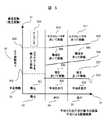
例として歩行者が上下方向に移動する可能性として、階段,エレベータがある場合を例にとる。また、分類のテーブル(6)の一例として分類テーブルの内容を図3に示す。 For example, as a possibility that a pedestrian moves in the vertical direction, a case where there are stairs and an elevator is taken as an example. FIG. 3 shows the contents of the classification table as an example of the classification table (6).
歩行者が平面上を移動する場合、上下移動に伴う気圧変動がないため観測される気圧変動はその時点における海面気圧に連動した気圧変動となる。この気圧変動は、低気圧や台風の通過により急激に変化する場合があるが数hPa以下である。例えば、2005年の台風11号通過時の横浜の最大気圧変動は26日AM3時からAM4時の1時間で5.1hPaとなっている。この気圧変動を高度の変動に変換すると約43mとなり、1時間の時間で約43m、1分で約70cmの高度変化を行ったのと同じ気圧変動が観測される。これに比べ、歩行者が階段を登る場合、通常1フロアー4m程度を10〜15秒程度で移動する。従って、1分では約16m移動することになり、台風接近時に比べ約20倍程度気圧勾配が異なってる。従って、この気圧勾配を利用してある気圧勾配を閾値として大きな気圧勾配の場合、上下移動のある移動と判断でき、気圧勾配がある閾値よりも小さい場合、平面上での移動と判断できる。図3では、横軸が歩行動態の種類、縦軸が気圧変動の有無を表している。気圧勾配の閾値は38のラインである。38を境に気圧変動が小さい場合が平面移動36、大きな場合が上下移動あり37と判定される。気圧勾配だけでは歩行動態に関してまでは判定できない。そこで、歩行動態の判定24で行った判定結果を組み合わせて歩行動態を判定する。図3の横軸が24で判定した結果である。33が静止状態、34が歩行状態、35が走行状態になっている。 When a pedestrian moves on a plane, the atmospheric pressure fluctuation observed is the atmospheric pressure fluctuation linked to the sea level air pressure at that time because there is no atmospheric pressure fluctuation accompanying vertical movement. This atmospheric pressure fluctuation is a few hPa or less although it may change abruptly due to the passage of a low atmospheric pressure or a typhoon. For example, the maximum atmospheric pressure fluctuation in Yokohama when Typhoon No. 11 passed in 2005 was 5.1 hPa in 1 hour from
気圧勾配で平面と判定(36)され、24で静止と判定された場合、平面移動との交点である平地で静止301が判定結果として出力される。同様に、歩行(34)の場合には、平地を歩行(302)が、走行(35)の場合には平地を走行(303)が認識結果となる。 If the pressure gradient is determined to be a plane (36), and if it is determined to be stationary at 24, the stationary 301 is output as a determination result on the flat ground that is the intersection with the plane movement. Similarly, in the case of walking (34), walking (302) is a recognition result on a flat ground, and in the case of traveling (35), traveling (303) is a recognition result.
気圧勾配で上下移動あり(37)と判定され、24で静止と判断された場合には、歩行者の動きが静止であるのに気圧変動があるのでエレベータで移動(304)と判断される。同様に、気圧勾配が37の領域であり歩行(34)と認識された場合には階段を歩いて移動(305)、走行(35)と判定された場合には階段を走って移動(306)と判断される。認識結果は28として出力される。 If it is determined that there is vertical movement (37) based on the atmospheric pressure gradient and it is determined that the movement is stationary at 24, it is determined that the movement is performed by the elevator (304) because there is a fluctuation in atmospheric pressure even though the movement of the pedestrian is stationary. Similarly, if the atmospheric pressure gradient is 37 and it is recognized as walking (34), it is moved by walking on the stairs (305), and if it is determined to be running (35), it is moved by running on the stairs (306). It is judged. The recognition result is output as 28.
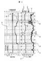
図4は本発明で判定した実際の例である。横軸は経過時間である。波形40は気圧データであり左側の軸がAD変換した値、右側が高度に変換した値になっている。波形42は23で抽出した歩調スペクトルの強度である。左側の軸にスペクトル強度の量が表記されている。スペクトル強度が0.05を超えると歩行状態と判定され0.4を超えると走行状態と判定される。この例では0.4 を超えるスペクトル強度が存在しないので、この区間では静止及び歩行のみを行っている。波形41が判定結果である。判定された結果は右の軸に記載されており、41の引き出し線付近は静止状態と判定されている。先ず区間43を見てみる。この区間では気圧の変動がなく、歩調スペクトルの強さが0.05〜0.1程度の値(歩行状態)を示している。従って、気圧勾配がなく歩行状態であるので歩行(平地での歩行)と判定されている。区間44では気圧勾配があり、動態は静止状態である。従って、エレベータと判断されている。このとき気圧勾配の傾きの符号を利用し、この例のように符号が正であるのでエレベータ上りと判定することも可能である。区間45では気圧勾配が正の傾きを持ち、歩調スペクトルの強さから歩行状態を表している。従って、階段を上っていると判定されている。区間46では、気圧勾配の傾きが負、動態が歩行状態であるので階段を下っていると判定されている。 FIG. 4 is an actual example determined by the present invention. The horizontal axis is the elapsed time. A
このように平面と仮定した歩行動態認識装置と気圧勾配による認識を組み合わせることにより上下運動を伴った歩行動態を認識できるようになる。 As described above, by combining the walking dynamic recognition device assumed to be a plane and the recognition based on the atmospheric pressure gradient, it becomes possible to recognize the walking dynamics accompanied with the vertical movement.
図5は高度勾配の閾値を図3によりも多くし、気圧勾配の閾値を歩行動作の激しさ(歩行に比べて走行の方が激しい)に応じ気圧勾配閾値に傾きを設け、更に多くの歩行動態を認識するようにした実施形態である。上下移動の認識対象は、階段の他に坂道,エスカレータを追加している。歩行者が静止状態における気圧勾配の閾値は、静止してエスカレータに乗っていると認識する閾値501とエレベータ移動と認識する502からなる。閾値501や閾値502は、エスカレータやエレベータの上昇速度をもとに決定される。歩行動作が伴っている場合、歩行による高度上昇変化を加える必要があるいため、エスカレータの高度上昇変化に加え、歩行の激しさ(速度)を加味した気圧勾配の閾値が必要になってくる。図5において気圧勾配の閾値直線504及び505が走行動作になるにつれて大きな閾値にしているのはそのためである。歩行動態の認識の振り分けは図3で行った装置と同様に、24で認識した結果と気圧勾配の閾値の関係より図5のテーブルにより行う。また同様に28から認識結果を出力する。 5 has a higher altitude gradient threshold than that in FIG. 3, and the gradient of the atmospheric pressure gradient is set according to the intensity of the walking motion (traveling is more intense than walking), and more walking is performed. This is an embodiment in which dynamics are recognized. In addition to the stairs, slopes and escalators are added as recognition targets for vertical movement. The threshold value of the atmospheric pressure gradient when the pedestrian is in a stationary state includes a
このように本実施形態では気圧勾配の閾値を上下移動方法に応じて複数設けることにより上下運動を伴った歩行動態の認識の種類を拡張できるようになる。 As described above, in this embodiment, by providing a plurality of atmospheric pressure gradient thresholds according to the vertical movement method, the types of recognition of walking dynamics accompanied by vertical movement can be expanded.
なお、上記実施形態では歩行動態の認識にとどまっているが、歩行動態より運動の消費カロリーも計算可能である。例えば、平面歩行の場合の消費カロリー,階段歩行での消費カロリーなど、歩行動態の違いにより消費する消費カロリーは異なっている。従って、前以て各歩行動態に対応する消費カロリーのテーブルを作成しておいて検知した歩行動態よりこのテーブルを参照することにより歩行動態に伴う運動消費カロリーを算出することができるようになる。 In the above embodiment, the gait dynamics is only recognized, but the calorie consumption of the exercise can be calculated from the gait dynamics. For example, the calorie consumption consumed differs depending on the walking dynamics such as the calorie consumption in the case of plane walking and the calorie consumption in the staircase walking. Therefore, a calorie consumption calorie corresponding to each walking dynamics is created in advance, and the calorie consumption associated with walking dynamics can be calculated by referring to this table based on the detected walking dynamics.
このように本実施形態では、歩行動態に応じた運動消費カロリーを検知することが出来るようになる。 Thus, in this embodiment, the exercise calorie consumption according to the walking dynamics can be detected.
次に、歩行動態の検知装置を利用し気圧センサなどで検知した高度を補正する実施形態について図9を用いて説明する。図4の波形40が高度検知装置(気圧センサ)で検知した出力である。このデータは実験の最初の時刻(時間0)と最後の時刻(時間240)では、同じ位置(同じ高度)で観測した場合の例である。従って、最初と最後では同じ高度を示すはずであるが、最初の高度(矢印48)と最後の高度(矢印49)を比べると最後の高度が若干上昇している。これは、先に台風の例で説明したように時間の経過と伴い低気圧の接近などにより気圧が変動したためである。こような気圧変動があると気圧計で求めた高度に誤差が生じることになる。そこで、図9に示すような処理フローを用い誤差を補正する。先ず、90で初期高度をセットする。これは、利用者が手動でセットしても良いし、GPSから出力される高度情報などを利用しても構わない。次に、上下移動を伴う歩行者の動態検知が可能である検知装置91(図1で説明した装置など)を用い、上下の移動を伴った動態か否かを92を用いて判定する。上下移動を伴う動態の場合、検知している高度勾配(4)は上下の移動に伴う気圧変動であるので93の1計算サイクル前の高度に高度変化を加える処理を行い94で高度を出力する。92で上下移動を伴う歩行動態でないと判断された場合、ここで観測された気圧勾配の値は、上下移動に伴う高度変化ではないので93の処理を行わないで1計算サイクル前の値と同じ高度として現在の高度を出力する(94)。以後、同じ処理を繰り返して高度を検知する。処理の結果が、図4の波形47である。48,49で生じていた高度差が補正され正しい高度を示していることがわかる。なお、本実施形態では、上下移動中の気圧変動(海面気圧)に関しては考慮していない。これは、通常平地歩行を行っている時間に比べ、上下移動を行っている時間は短く、上下移動中の海面気圧変動を考慮しないでも大きな誤差とならないためである。 Next, an embodiment for correcting altitude detected by a barometric sensor or the like using a walking dynamic detection device will be described with reference to FIG. A
本実施形態によれば、上下移動を伴う歩行動態の区間だけ気圧変の量を考慮することにより、海面気圧変動の影響を補正する湖とが可能になる。 According to the present embodiment, a lake that corrects the influence of sea level pressure fluctuations can be obtained by considering the amount of atmospheric pressure change only in the walking dynamics section that involves vertical movement.
次に、上記発明で認識した歩行動態を利用し上下移動を伴う歩行においても正確な歩幅を推定し位置検知技術に応用する装置について図6及び図7を用いて説明する。図7が歩幅推定及び位置検知を行うための構成図、図6は歩幅推定を行うための説明図である。平面歩行における歩行者の移動速度(移動距離)の推定は従来技術で述べられているが、大まかに下記のような処理を行う。
(1)上下の加速度変化波形を周波数解析し歩調を表す周波数とそのスペクトル強度を抽出する。
(2)これより歩幅は
歩幅=歩調スペクトルの強度×動作毎の係数
(動作毎の係数は歩行と走行では歩行形態が異なり歩幅に変換する係数が異なる値を利用する)
(3)歩幅から移動速度は
移動速度=歩幅×歩調
(4)移動距離
移動距離=移動速度の時間積分
で求めている。水平面を移動する場合、歩行動態の違いによる歩幅の変動を考慮しているため、歩いた場合でも走った場合でも正確な移動速度を求めることが出来る。処が、階段を移動する場合、上り方向と下り方向では異なった強さのスペクトル強度を示してしまい(図4の区間45及び区間46)、上りと下りで異なった移動距離となってしまう。これは、上り階段に比べ下り階段では着地時に受ける加速度が大きいためである。また、階段の踏面の寸法は一定であるので歩行動態の違いにより歩幅が変化することはない(段飛ばしは除く)。Next, an apparatus that uses the walking dynamics recognized in the above-described invention and estimates an accurate stride even in walking with vertical movement and applies it to the position detection technique will be described with reference to FIGS. FIG. 7 is a configuration diagram for performing stride estimation and position detection, and FIG. 6 is an explanatory diagram for performing stride estimation. The estimation of the movement speed (movement distance) of a pedestrian in a plane walk is described in the prior art, but the following processing is roughly performed.
(1) The frequency of the acceleration change waveform in the vertical direction is analyzed to extract the frequency representing the pace and its spectrum intensity.
(2) From here on, the stride is stride = intensity of pace spectrum × coefficient for each action (coefficient for each action uses different values for different walking modes and different coefficients for converting to stride)
(3) The moving speed is calculated from the step length by the time integration of moving speed = step length × stepping (4) moving distance moving distance = moving speed. When moving on a horizontal plane, since the change in the stride due to the difference in walking dynamics is taken into account, it is possible to obtain an accurate moving speed even when walking or running. However, when the stairs are moved, the spectrum intensity having different strengths is shown in the upward direction and the downward direction (
そこで、図7の70の上下移動を考慮した歩幅推定装置を用いて推定を行う。70には動態の認識装置(2)で得られる歩調スペクトルの周波数と歩調スペクトルの強さ及び歩行の動態認識結果出力(7)が入力データして利用される。70の処理内容を図6を用いて説明する。60及び61は加速度センサ単独で認識した歩行の状態を表している。60が歩行、61が走行である。動態認識結果出力(7)で平地移動(63)と認識された場合には、平地移動での歩幅推定計算(従来技術の歩幅推定方法)65及び66を行う。階段移動(64)と認識された場合には歩行動態に依存せず67のように固定歩幅×歩調の計算を行い移動速度を算出する。この固定歩幅の値は、標準的な踏面の長さ約30cm程度にしてもよいし、精度を上げるために階段の踏面の長さを地理情報の中に入れておき、歩行者が通過している階段の踏面の長さを利用してもかまわない(歩行者がどこの階段を通過しているかを判断する装置については後述する)。このようにして歩幅(移動速度)を推定した後は、71の進行方向の検知装置で歩行者の移動方向を検知し、72の移動軌跡の算出方法で、移動速度と移動方向を積分し移動軌跡を求め、移動軌跡を出力(73)できるようになる。 Therefore, the estimation is performed using the
本実施形態では、階段などの上下移動を伴うような歩行形態でも正確な歩幅推定を行う事ができるようになり、またこの歩幅より移動軌跡を推定できるようにもなる。 In the present embodiment, it becomes possible to accurately estimate the stride even in a walking form that involves vertical movement such as stairs, and it is also possible to estimate the movement trajectory from this stride.
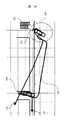
次に、認識した歩行者の動態と周囲の地理情報を比較し認識した歩行状態に対応する位置を推定する実施形態について、図8,図10を用いて説明する。図8は階段移動の説明図である。図10は本実施形態を実現するための構成図である。図10の101は歩行動態の認識装置でありこれまで説明してきた、上下方向の移動を含む歩行動態を認識する装置である。102は歩行者の位置検知装置である。例えば、図7で説明した歩幅推定による移動軌跡の検知装置でもかまわないしGPSや無線LANによる位置検知装置でもかまわない。この実施形態で説明する位置検知装置は、102による位置検知装置により検知された位置情報よりも更に高精度な位置を検知することが目的である。103は地理情報であり、建物の位置や階段・エレベータ等の建物内部の構造や位置情報、更に外の道路や地形情報が格納されている。104は歩行動態による地理情報の検索方法である。ここでは、102で検知した歩行動態に対応する地理情報の位置を大まかな位置情報102を用い103のデータベースから探索する処理を行う。ここで、歩行動態に対応する地理情報とは、階段歩行=「階段の地理情報」,エレベータ移動=「エレベータの地理情報」,エスカレータ移動=「エスカレータの地理情報」等を示している。従って、階段歩行を認識している場合歩行者は階段の場所にいることになるので階段の地理情報を参照することにより階段の位置情報などが取得できるようになる。階段が複数ある場合を想定し、102で検知した歩行者の大まかな位置情報を元に103の地理情報データベースから一番近くにある対応する地理情報を探索する。これにより歩行者動態検知結果とおおまかな現在位置から対応する地理情報を探索するかとが出来、地理情報の中の位置情報から位置を推定できるようになる。(ここまでは、特開平10−113343号公報と同様の処理である)更に、108の歩行動態の変化を利用した地理情報変化点の検知と進行方向検知処理を用いて検知精度の向上と進行方向の検知を行う。処理の方法を図8及び図9を用いて説明する。80は階段を表している104の処理で歩行者がこの階段の中にいると判定されているとする。この階段は87に示すように上り方向が北、下り方向が南側を向いている。歩行者が区間81(階段)から区間82(平地)へ向かった場合を考える。この場合、歩行者の動態認識結果は区間81を移動中には「上り階段」、区間82を移動中は「平面歩行」と認識される。従って、動態認識結果が「上り階段」から「平面歩行」へ変化する85の地点は上り階段の終点となる。階段の形状と位置データは地理情報データベースの中に格納されているのでこの情報を元に85の位置を割り出す事が出来る。このように、歩行動態の変化点を参照することにより104で検索した結果よりも更に詳細な位置情報を求めることが出来る。更に、この階段は上り方向は北に向かっているので階段を上っている歩行者は北を向いて歩行していることになる。従って、歩行者の進行方向も検知できるようになる。下りの場合も同様である。区間83では「下り階段」区間84では「平面歩行」と認識されその変化点が下り階段の終点である86の位置となる。進行方向は下り階段を歩行してきたので南方向に移動していると判定される。 Next, an embodiment in which the position corresponding to the recognized walking state is estimated by comparing the recognized pedestrian dynamics and the surrounding geographic information will be described with reference to FIGS. FIG. 8 is an explanatory diagram of stair movement. FIG. 10 is a configuration diagram for realizing the present embodiment.
このように、本実施形態では歩行動態の認識結果と地理情報を比較し歩行者がいる場所を推定する事が可能になり、歩行者の現在位置と進行方向を検知することができるようになる。 As described above, in this embodiment, it is possible to estimate the place where the pedestrian is present by comparing the recognition result of the walking dynamics and the geographic information, and to detect the current position and the traveling direction of the pedestrian. .
次に、前述の歩行動態の検知装置を利用した位置及び進行方向の検知装置を利用し、単位時間あたりの速度と進行方向を積分して位置を検知する装置(自立的位置検知装置あるいは慣性航法)の位置補正として利用する実施形態について図11,図12,図13を用いて説明する。図11は本実施形態の処理フロー、図12及び図13は検知した移動軌跡の例である。 Next, a device that detects the position by integrating the speed and the traveling direction per unit time using the position and traveling direction detecting device using the above-described walking dynamics detecting device (autonomous position detecting device or inertial navigation) ) Will be described with reference to FIGS. 11, 12, and 13. FIG. FIG. 11 shows a processing flow of this embodiment, and FIGS. 12 and 13 show examples of detected movement trajectories.
図12は、図7を用いて説明した装置で求めた移動軌跡の例である。125は出発位置、120及び121は階段である。図12の例で実際に歩行した経路は、125を出発点として階段120を3フロアー分上り3フロアー上の階層を階段121の階段の方向に移動し121の階段を3フロアー分下がり再度125の地点に戻るように行った。実際に図7の装置で検知した移動軌跡は124である。125の出発地点から120の階段までは正確な移動軌跡を示している。処が、120の階段を上っている間に、ジャイロなどの方向検知センサのドリフトのために方位に誤差が蓄積してしまい階段121に到達していると考えられる点線で囲んだ領域123になっても移動軌跡124は階段の121の位置に達していない。本実施形態ではこのような状況に陥っても正確な位置に補正する装置を提供する。先ず、図11の110で歩行者の初期位置をセットする。歩行者が自分の位置を地図から確認して位置座標や進行方向を入力しても良いし、GPSなど絶対位置の検知できる装置が使える領域であればこの装置で検知した絶対位置及び進行方向を入力データとしてもかまわない、或はRFIDなどを利用して位置に対応するID情報を発信するタグなどを敷設し、このID情報を読み取る事により位置情報を検知し検知した位置情報を入力データとしてもかまわない。111で歩行動態の検知及び地理情報を利用した位置及び進行方向の推定方法の処理を行う。この処理は例えば図10で説明した装置を用いる。ここでは(1)位置及び進行方向の推定が可能か否かの判断、(2)可能な場合の位置及び進行方向の算出を行う。位置及び進行方向の推定が可能な場合分岐112により113の推定した位置及び進行方向を用い現在位置及び進行方向の再セットを行う。位置及び進行方向の推定が可能な場合とは、階段の上り下りなどを認識し該当する位置が推定できた場合である。例えば、図12,図13の例では、階段120及び121を歩行者が通過した場合にこの状検知なり、階段の位置及び進行方向が再セットされる。その後114の単位時間ごとの速度と進行方向検知装置で速度と進行方向を検知し(例えば図7で説明した装置)、115において時間積分を行い移動軌跡を算出し116で現在の位置と進行方向が出力される。分岐112で位置及び進行方向が推定できない場合(階段以外の場所を歩行中など)は113の再セット処理を行わず、114,115の処理を行い116で現在の位置と進行方向が出力される。以後、再度111の処理に戻り処理を繰り返して連続的に位置と進行方向情報を出力する。図13は、図12と同じデータを用い本実施形態の効果を示したものである。132から出発した移動軌跡は階段の領域134に入ると120の階段の位置と進行方向に合致するように補正されていいる(途中移動軌跡が切れている場所が補正処理が行われた場所)。更に、121の階段の領域131へ進むと、同様に階段121の位置と進行方向が合致するように補正されている。最終的に終点133に到達するが出発点132とほぼ同じ位置となっており図12の終点126に比べ位置検知精度が向上していることがわかる。 FIG. 12 is an example of the movement locus obtained by the apparatus described with reference to FIG. 125 is a starting position, and 120 and 121 are stairs. The route actually walked in the example of FIG. 12 starts from 125 and goes up
なお、上記実施形態では、GPSによる位置補正は、初期位置のセット(110)のみに利用しているが、分岐112において動態検知による位置補正に加え、GPSの精度が信頼できるか否かの判断を行い精度が信頼できる値の場合、113の補正値をGPSの値を用いて行ってもかまわない。精度が信頼できるか否かの判定はDOPなどの情報をりようしてもかまわない。また、動態検知による位置補正及びGSPによる位置検知両方が位置検知可能と判断された場合には、精度が高い動態検知による位置補正を選択してもかまわない。 In the above embodiment, the position correction by GPS is used only for the initial position set (110). However, in addition to the position correction by dynamic detection at the
本実施形態によれば、自律位置検知装置の補正装置として利用する事ができ、誤差が時間と共に増加する、自律位置検知装置の位置補正手段として利用できる。 According to this embodiment, it can be used as a correction device for an autonomous position detection device, and can be used as a position correction means for an autonomous position detection device in which an error increases with time.
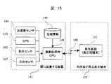
次に、本発明を利用した歩行者ナビゲーション端末に関して図14を用いて説明する。144は加速度センサ、142は気圧センサ、147は方向センサ(磁気方位やジャイロセンサ)である。143はGPS装置である。146は地理情報のデータベース、141が演算処理用CPU、145が表示装置となっている。これらの装置が一体化され140が歩行者ナビゲーション端末となっている。 Next, a pedestrian navigation terminal using the present invention will be described with reference to FIG. 144 is an acceleration sensor, 142 is a barometric pressure sensor, and 147 is a direction sensor (magnetic azimuth or gyro sensor).
144は図1の動態変化信号の検知装置(1)に142は高度検知装置(3)に対応するセンサである。141演算処理用CPUでは、144及び142の情報をもとに図1を用いて説明した歩行者の動態検知、147のセンサを追加して利用し図7を用いて説明した歩行者の移動軌跡の検知装置、図10を用いて説明した歩行動態による位置及び方向の検知装置などが処理される。また、143のGPSはGPS衛星の電波が良好に受信できる屋外などでは、GPSから取得した位置情報を自分の位置としてそのまま利用したり、受信状態が悪くなる直前の値を図11で説明した装置の110の初期位置のリセット情報として利用する。146は地理情報であり、歩行動態の検知結果から対応する地理情報
(階段の位置など)を探索したり、図11で説明した移動軌跡の検知装置で求めた移動軌跡と、周囲の地理情報(建物や階段,道などの情報)を描画するためのデータが格納されている。146及び141で処理した結果が145の表示装置を用いて描画される。描画される情報としては、図1により求めた歩行動態の検知結果や運動消費カロリー、図7や図10,図11により求めた歩行者の現在の移動軌跡とそれと重ねて表示した地理情報などである。これにより端末140を持った歩行者は、自分が今どこにいるかを表示画面
145を見ることにより確認できるようになり自分がどこにいるかを把握できるようになる。なお、本実施形態では、自分の現在位置と移動軌跡の検知方法について述べているが、これらの情報をもとにカーナビゲーション(以下カーナビ)で一般的に行われている、経路探索情報をもとにした経路案内を行っても構わない。カーナビと本実施例の違いは、(1)GPSが使える領域ではカーナビと同様、(2)GPSが使えない場合、カーナビでは移動距離を車速パルスなどを利用するが本実施形態では歩幅推定技術を利用、(3)位置検知誤差が生じる場合、カーナビでは道路に沿って位置を補正(マップマッチング)するが、本実施形態では歩行動態に対応した地理情報(階段やエレベータ,エスカレータなど)で補正する違いがある。144 is a sensor corresponding to the dynamic change signal detection device (1) in FIG. 1, and 142 is a sensor corresponding to the altitude detection device (3). In the 141 arithmetic processing CPU, the pedestrian movement detection described with reference to FIG. 7 by using the pedestrian dynamic detection described with reference to FIG. And the position and direction detection device based on walking dynamics described with reference to FIG. 10 are processed. In addition, in the outdoor where GPS radio waves can be satisfactorily received by the GPS of 143, the position information acquired from the GPS is used as it is as it is, or the value immediately before the reception state is deteriorated is described in FIG. 110 is used as reset information of the
本実施形態によれば歩行者用のナビゲーションが可能になる。 According to this embodiment, navigation for pedestrians becomes possible.
次に、表示画面(表示用端末)151を分離した例を図15に示す。図14との違いは、表示画面を分離しただけで処理内容は同様である。これは、歩行者の動態検知や歩幅推定を行うためには、144の加速度センサや147の方向センサを人間の重心位置である腰の位置に置くのが望ましい。処が、図14の例の場合、通常腰の位置に取りつけて検知処理を行ったとしても、現在位置を確認するために画面を見る必要があり、結果的に腰から外し画面を見る動作により検知結果に誤認識や位置検知誤差が生じてしまう可能性が出てくる。従って、図15の例では、センサ部分を搭載した152のくしに装着する装置と、利用者が手に持って画面などを確認できる利用者が見る表示端末153に分離して、通信回線150を用い画面情報等の情報をやり取りしながら表示する構成にしている。通信回線150は有線でも良いし無線を用いても構わない。これにより、画面と歩行者の動態検知を行うセンサを分離する事が可能になるので歩行動態の誤認識や位置検知誤差が生じにくくなる。なお、端末分離の目的は、歩行者の動態検知を行うセンサを一番条件の良い場所に配置するのが目的である。図15の構成では演算用CPUや地理情報146を腰に装着する端末側に配置しているが、位置精度に影響を与える144や147だけを腰に装着する端末152側に配置しその他のセンサや処理回路を153の利用者が見る表示端末側に配置しても構わない。 Next, an example in which the display screen (display terminal) 151 is separated is shown in FIG. The difference from FIG. 14 is that the processing contents are the same except that the display screen is separated. In order to detect a pedestrian's dynamics or to estimate a stride, it is desirable to place 144 acceleration sensors and 147 direction sensors at the waist position, which is the human center of gravity. However, in the case of the example of FIG. 14, even if the detection process is performed by attaching to the position of the normal waist, it is necessary to look at the screen in order to confirm the current position. There is a possibility that misrecognition or position detection error may occur in the detection result. Accordingly, in the example of FIG. 15, the
本実施形態によれば、歩行動態の検知精度や移動軌跡の検知精度に影響を与えるセンサ群を条件の良い場所に分離して配置できるといった効果がある。 According to the present embodiment, there is an effect that the sensor group that affects the detection accuracy of the walking dynamics and the detection accuracy of the movement trajectory can be separated and arranged in a well-conditioned place.
次に、作業員の状態検知用システムに利用する場合の実施形態を図16の構成図を用いて説明する。160の作業員が取り付ける作業員端末160と作業員から離れた場所に配置する作業員監視用装置167から構成される。作業員用の端末(160)は図14で説明した構成図に通信装置161が追加されている。作業員用端末160では、図14で説明した処理機能が搭載されており、歩行者(作業員)の動態や位置検知・移動軌跡検知を行う事ができる。これらの情報は、図14で説明したのと同様に作業員が表示装置145を用いて見ることが出来るが、通信装置161を用いて遠隔地に置かれた作業員監視用装置167へ転送することが可能になっている。162は通信回線(無線通信など)、163は通信装置、164は地理情報データベース、165は処理用PC,166表示装置になっている。162を介して送られて来た作業員用の端末160で検知した情報は、163の通信装置で受信され処理用PC165へ送られる。処理用PC165では送られて来た情報の描画処理などを行う。例えば、歩行者(作業員)の動態検知結果が送られて来た場合、その動態(「歩く」「走る」「階段を上る」など)の結果を画像情報に変換して表示装置166へ送って描画する。移動軌跡や位置・進行方向情報が送られて来た場合には、地理情報164の情報と重ね合わせて、歩行者(作業員)が地図上のどこにいるかを描画することが出来る。従って、作業員監視用装置167を用いることにより遠隔地から作業員の動態や位置を検知する事が可能になる。なお、図16では作業員端末は1つ書かれているが、複数の端末と接続し、複数の作業員の動態情報や位置情報を描画することも可能である。また、160は画面とセンサ群が一体型の端末であるが図15で説明したようにセンサ群と表示画面を分離してもかまわない。 Next, an embodiment in which the present invention is used for a worker state detection system will be described with reference to the block diagram of FIG. It includes a
本実施形態によれば、作業員の位置及び動態を遠隔地から検知可能になる。 According to the present embodiment, the position and dynamics of the worker can be detected from a remote location.
上記、実施例によれば、つぎのような作用・効果を生じる。 According to the above embodiment, the following operations and effects are produced.
平面と仮定した歩行動態認識装置と気圧勾配による認識を組み合わせることにより上下運動を伴った歩行動態を認識できるようになる。 By combining a walking dynamic recognition device that is assumed to be a plane and recognition based on atmospheric pressure gradient, it becomes possible to recognize walking dynamics accompanied by vertical movement.
歩行動態に応じた運動消費カロリーを検知することが出来るようになる。 The exercise calorie consumption according to the walking dynamics can be detected.
上下移動を伴う歩行動態の区間だけ気圧変の量を考慮することにより、海面気圧変動の影響を補正することが可能になる。 It is possible to correct the influence of sea level pressure fluctuations by considering the amount of atmospheric pressure change only in the walking dynamics with vertical movement.
階段などの上下移動を伴うような歩行形態でも正確な歩幅推定を行う事ができるようになり、またこの歩幅より移動軌跡を推定できるようにもなる。 It is possible to accurately estimate the stride even in a walking form involving up and down movement such as stairs, and it is also possible to estimate the movement trajectory from this stride.
歩行動態の認識結果と地理情報を比較し歩行者がいる場所を推定する事が可能になり、歩行者の現在位置と進行方向を検知することができるようになる。 It becomes possible to estimate the place where the pedestrian is present by comparing the recognition result of the walking dynamics and the geographic information, and the current position and the traveling direction of the pedestrian can be detected.
自律位置検知装置の補正装置として利用する事ができ、誤差が時間と共に増加する、自律位置検知装置の位置補正手段として利用できる。 It can be used as a correction device for an autonomous position detection device, and can be used as a position correction means for an autonomous position detection device in which an error increases with time.
歩行者用のナビゲーションが可能になる。また、作業員の位置及び動態を遠隔地から検知可能になる。 Navigation for pedestrians is possible. In addition, the position and dynamics of the worker can be detected from a remote location.
1…動態検知信号の検知装置、2…動態の認識装置、3…高度検知装置、4…高度変化勾配の検知装置、5…組合せ分類・認識処理、6…分類用テーブル。
DESCRIPTION OF
Claims (10)
Translated fromJapaneseThe pedestrian movement detection device according to any one of claims 1, 2, 3, 4, 5, 6, 7, and 8, wherein the remote position and movement detection of the worker is realized.
Priority Applications (3)
| Application Number | Priority Date | Filing Date | Title |
|---|---|---|---|
| JP2005284426AJP2007093433A (en) | 2005-09-29 | 2005-09-29 | Detector for motion of pedestrian |
| US11/528,329US7811203B2 (en) | 2005-09-29 | 2006-09-28 | Walker behavior detection apparatus |
| EP06255079AEP1770370B1 (en) | 2005-09-29 | 2006-09-29 | Walker behavior detection apparatus |
Applications Claiming Priority (1)
| Application Number | Priority Date | Filing Date | Title |
|---|---|---|---|
| JP2005284426AJP2007093433A (en) | 2005-09-29 | 2005-09-29 | Detector for motion of pedestrian |
Publications (1)
| Publication Number | Publication Date |
|---|---|
| JP2007093433Atrue JP2007093433A (en) | 2007-04-12 |
Family
ID=37499727
Family Applications (1)
| Application Number | Title | Priority Date | Filing Date |
|---|---|---|---|
| JP2005284426APendingJP2007093433A (en) | 2005-09-29 | 2005-09-29 | Detector for motion of pedestrian |
Country Status (3)
| Country | Link |
|---|---|
| US (1) | US7811203B2 (en) |
| EP (1) | EP1770370B1 (en) |
| JP (1) | JP2007093433A (en) |
Cited By (57)
| Publication number | Priority date | Publication date | Assignee | Title |
|---|---|---|---|---|
| JP2008027429A (en)* | 2006-06-19 | 2008-02-07 | Adc Technology Kk | Motion detector, position relation detector, physical activity load detector, and portable monitor |
| JP2009018103A (en)* | 2007-07-13 | 2009-01-29 | Fujitsu Ltd | Measuring method, measuring apparatus and measuring program |
| JP2009077825A (en)* | 2007-09-25 | 2009-04-16 | Panasonic Electric Works Co Ltd | Oscillating motion device |
| JP2009192506A (en)* | 2008-02-18 | 2009-08-27 | Seiko Instruments Inc | Walk simulation apparatus |
| JP2009204568A (en)* | 2008-02-29 | 2009-09-10 | Seiko Instruments Inc | Walk simulation apparatus |
| JP2009210473A (en)* | 2008-03-05 | 2009-09-17 | Sumitomo Electric Ind Ltd | Position specifying device, computer program, and position specifying method |
| JP2009229204A (en)* | 2008-03-21 | 2009-10-08 | Sumitomo Electric Ind Ltd | Location specifying system, computer program and location specifying method |
| JP2009229205A (en)* | 2008-03-21 | 2009-10-08 | Sumitomo Electric Ind Ltd | Pedestrian guidance system, computer program and pedestrian guiding method |
| JP2009287984A (en)* | 2008-05-28 | 2009-12-10 | Casio Comput Co Ltd | Position detecting device and position detecting program |
| JP2010110399A (en)* | 2008-11-05 | 2010-05-20 | Hirosaki Univ | System for evaluation of walking characteristic and track generation method |
| JP2010216987A (en)* | 2009-03-17 | 2010-09-30 | Seiko Epson Corp | Method and device for estimating stride |
| JP2010227326A (en)* | 2009-03-27 | 2010-10-14 | Advanced Telecommunication Research Institute International | Action identification system |
| JP2010536040A (en)* | 2007-08-08 | 2010-11-25 | ディーピー テクノロジーズ インコーポレイテッド | Human behavior monitoring device including distance calculation |
| JP2011506913A (en)* | 2007-07-12 | 2011-03-03 | コミシリア ア レネルジ アトミック | Support device for human navigation |
| JP2011117818A (en)* | 2009-12-03 | 2011-06-16 | National Institute Of Advanced Industrial Science & Technology | Altitude measuring device of moving body |
| WO2011089991A1 (en)* | 2010-01-20 | 2011-07-28 | オムロンヘルスケア株式会社 | Body movement detection device |
| WO2012008207A1 (en)* | 2010-07-16 | 2012-01-19 | オムロンヘルスケア株式会社 | Exercise detection device and exercise detection device control method |
| JP2012215408A (en)* | 2011-03-31 | 2012-11-08 | Zenrin Datacom Co Ltd | Navigation device |
| JP2012215409A (en)* | 2011-03-31 | 2012-11-08 | Zenrin Datacom Co Ltd | Navigation device |
| JP2012237719A (en)* | 2011-05-13 | 2012-12-06 | Kddi Corp | Portable device for estimating ascending/descending movement state by using atmospheric pressure sensor, program, and method |
| JP2012532319A (en)* | 2009-06-30 | 2012-12-13 | クゥアルコム・インコーポレイテッド | Trajectory-based location determination |
| KR101250215B1 (en) | 2012-05-31 | 2013-04-03 | 삼성탈레스 주식회사 | Pedestrian dead-reckoning system using kalman filter and walking state estimation algorithm and method for height estimation thereof |
| JP2013130495A (en)* | 2011-12-22 | 2013-07-04 | Hitachi Ltd | Information processor and information processing method |
| JP2013130491A (en)* | 2011-12-22 | 2013-07-04 | Hitachi Ltd | Information processor and information processing method |
| JP2013200156A (en)* | 2012-03-23 | 2013-10-03 | Seiko Epson Corp | Altitude measuring device, navigation system, program, and recording medium |
| JP2013255608A (en)* | 2012-06-11 | 2013-12-26 | Nippon Telegr & Teleph Corp <Ntt> | Gait measurement device, method and program |
| JP2013257238A (en)* | 2012-06-13 | 2013-12-26 | Hitachi Ltd | Information processing system, and information processing method |
| JP2013255786A (en)* | 2012-05-18 | 2013-12-26 | Kao Corp | Evaluation method for geriatric disorder risk |
| JP2014006089A (en)* | 2012-06-22 | 2014-01-16 | Seiko Epson Corp | Portable device |
| WO2014097348A1 (en)* | 2012-12-18 | 2014-06-26 | 富士通株式会社 | Method for controlling information processing device, control program, and information processing device |
| KR20140090071A (en)* | 2013-01-08 | 2014-07-16 | 삼성전자주식회사 | Method for determining user exercies information and apparatus for the same |
| JP2014169931A (en)* | 2013-03-04 | 2014-09-18 | Seiko Instruments Inc | Electronic apparatus |
| US8872646B2 (en) | 2008-10-08 | 2014-10-28 | Dp Technologies, Inc. | Method and system for waking up a device due to motion |
| US8876738B1 (en) | 2007-04-04 | 2014-11-04 | Dp Technologies, Inc. | Human activity monitoring device |
| WO2014192271A1 (en)* | 2013-05-31 | 2014-12-04 | 旭化成株式会社 | Device for identifying changes in vertical direction using pressure measurement values |
| JP2015054010A (en)* | 2013-09-11 | 2015-03-23 | カシオ計算機株式会社 | Exercise support device and exercise support method, and exercise support program |
| WO2015170703A1 (en)* | 2014-05-09 | 2015-11-12 | アルプス電気株式会社 | Movement detection program, object movement detection device and method therefor |
| WO2016098457A1 (en)* | 2014-12-17 | 2016-06-23 | ソニー株式会社 | Information processing device, information processing method, and program |
| KR101642286B1 (en)* | 2015-02-12 | 2016-07-25 | 한국항공우주연구원 | Heading Orientation Estimation Method Using Pedestrian Characteristics in Indoor Environment |
| JP2016150034A (en)* | 2015-02-16 | 2016-08-22 | 沖電気工業株式会社 | Posture estimation device, posture estimation system, posture estimation method, and program |
| JP2017034642A (en)* | 2015-07-28 | 2017-02-09 | 京セラ株式会社 | Mobile device, moving state detection method, and moving state detection program |
| JP2017067507A (en)* | 2015-09-28 | 2017-04-06 | 京セラ株式会社 | Portable device, control method and control program |
| JP2017181179A (en)* | 2016-03-29 | 2017-10-05 | Kddi株式会社 | Device, program and method for position estimation capable of correction of position based on transition between floors |
| JP2017195623A (en)* | 2017-06-12 | 2017-10-26 | 京セラ株式会社 | Portable device, control method and control program |
| JP2018009961A (en)* | 2016-06-30 | 2018-01-18 | セイコーインスツル株式会社 | Electronic apparatus, display system, electronic watch, and program |
| JP2018028485A (en)* | 2016-08-18 | 2018-02-22 | 株式会社ゼンリンデータコム | Information processing apparatus, information processing method, and program |
| JP2018028483A (en)* | 2016-08-18 | 2018-02-22 | 株式会社ゼンリンデータコム | Information processing apparatus, information processing method, and program |
| JP2018031668A (en)* | 2016-08-24 | 2018-03-01 | 京セラ株式会社 | Electronic device, control method, and control program |
| JP2018096829A (en)* | 2016-12-13 | 2018-06-21 | 京セラ株式会社 | Electronic device, correction control method, and correction control program |
| KR20180081187A (en)* | 2016-12-28 | 2018-07-16 | 주식회사 스탠딩에그 | Method and apparatus for tracking a gait |
| JPWO2017104646A1 (en)* | 2015-12-18 | 2018-09-13 | 株式会社リコー | Information processing system, information processing apparatus, information processing method, program, and recording medium |
| JP2018169886A (en)* | 2017-03-30 | 2018-11-01 | セコム株式会社 | Imaging abnormality monitoring system and program |
| US10405781B2 (en) | 2015-07-28 | 2019-09-10 | Kyocera Corporation | Mobile device, movement state detection method, and non-transitory storage medium storing movement state detection program |
| JP2019535334A (en)* | 2016-01-25 | 2019-12-12 | ビーテミア インコーポレイテッド | Gait profiler system and method |
| WO2020003952A1 (en)* | 2018-06-26 | 2020-01-02 | コニカミノルタ株式会社 | Computer executable program, information processing device, and computer execution method |
| CN110638456A (en)* | 2018-06-27 | 2020-01-03 | 斯沃奇集团研究和开发有限公司 | Method for calculating real-time step size and speed of running or walking individual |
| JP2020137801A (en)* | 2019-02-28 | 2020-09-03 | トヨタ自動車株式会社 | Posture estimation device for people, etc. |
Families Citing this family (56)
| Publication number | Priority date | Publication date | Assignee | Title |
|---|---|---|---|---|
| JP4500184B2 (en)* | 2005-02-28 | 2010-07-14 | Npo法人熟年体育大学リサーチセンター | Endurance calculation device, endurance calculation method and program |
| US8949070B1 (en) | 2007-02-08 | 2015-02-03 | Dp Technologies, Inc. | Human activity monitoring device with activity identification |
| US8180379B2 (en) | 2007-06-28 | 2012-05-15 | Apple Inc. | Synchronizing mobile and vehicle devices |
| US8204684B2 (en)* | 2007-06-28 | 2012-06-19 | Apple Inc. | Adaptive mobile device navigation |
| US8332402B2 (en) | 2007-06-28 | 2012-12-11 | Apple Inc. | Location based media items |
| US8175802B2 (en) | 2007-06-28 | 2012-05-08 | Apple Inc. | Adaptive route guidance based on preferences |
| US8275352B2 (en) | 2007-06-28 | 2012-09-25 | Apple Inc. | Location-based emergency information |
| US8108144B2 (en) | 2007-06-28 | 2012-01-31 | Apple Inc. | Location based tracking |
| US8762056B2 (en) | 2007-06-28 | 2014-06-24 | Apple Inc. | Route reference |
| US8774825B2 (en) | 2007-06-28 | 2014-07-08 | Apple Inc. | Integration of map services with user applications in a mobile device |
| US8290513B2 (en) | 2007-06-28 | 2012-10-16 | Apple Inc. | Location-based services |
| US9109904B2 (en) | 2007-06-28 | 2015-08-18 | Apple Inc. | Integration of map services and user applications in a mobile device |
| US8385946B2 (en) | 2007-06-28 | 2013-02-26 | Apple Inc. | Disfavored route progressions or locations |
| US9066199B2 (en) | 2007-06-28 | 2015-06-23 | Apple Inc. | Location-aware mobile device |
| US8311526B2 (en) | 2007-06-28 | 2012-11-13 | Apple Inc. | Location-based categorical information services |
| US8555282B1 (en) | 2007-07-27 | 2013-10-08 | Dp Technologies, Inc. | Optimizing preemptive operating system with motion sensing |
| DE102007043490A1 (en)* | 2007-09-12 | 2009-03-19 | Robert Bosch Gmbh | Method and device for detecting a distance |
| JP5202933B2 (en)* | 2007-11-30 | 2013-06-05 | 株式会社タニタ | Body motion detection device |
| US8355862B2 (en) | 2008-01-06 | 2013-01-15 | Apple Inc. | Graphical user interface for presenting location information |
| CN106139548A (en)* | 2008-02-27 | 2016-11-23 | 耐克创新有限合伙公司 | Movable information system and method |
| US9250092B2 (en) | 2008-05-12 | 2016-02-02 | Apple Inc. | Map service with network-based query for search |
| US8644843B2 (en) | 2008-05-16 | 2014-02-04 | Apple Inc. | Location determination |
| US8996332B2 (en) | 2008-06-24 | 2015-03-31 | Dp Technologies, Inc. | Program setting adjustments based on activity identification |
| US8369867B2 (en) | 2008-06-30 | 2013-02-05 | Apple Inc. | Location sharing |
| US8187182B2 (en)* | 2008-08-29 | 2012-05-29 | Dp Technologies, Inc. | Sensor fusion for activity identification |
| US8359643B2 (en) | 2008-09-18 | 2013-01-22 | Apple Inc. | Group formation using anonymous broadcast information |
| US8150624B2 (en) | 2008-11-11 | 2012-04-03 | Northrop Grumman Systems Corporation | System and method for tracking a moving person |
| US8260320B2 (en) | 2008-11-13 | 2012-09-04 | Apple Inc. | Location specific content |
| KR20100087551A (en)* | 2009-01-28 | 2010-08-05 | 한국과학기술연구원 | Apparatus for calculating calorie balance by classfying user's activity |
| US20100250134A1 (en)* | 2009-03-24 | 2010-09-30 | Qualcomm Incorporated | Dead reckoning elevation component adjustment |
| JP5559305B2 (en)* | 2009-04-20 | 2014-07-23 | オーチス エレベータ カンパニー | Automatic adjustment of parameters for safety devices |
| US8666367B2 (en) | 2009-05-01 | 2014-03-04 | Apple Inc. | Remotely locating and commanding a mobile device |
| US8660530B2 (en) | 2009-05-01 | 2014-02-25 | Apple Inc. | Remotely receiving and communicating commands to a mobile device for execution by the mobile device |
| US8670748B2 (en) | 2009-05-01 | 2014-03-11 | Apple Inc. | Remotely locating and commanding a mobile device |
| AU2010202019B2 (en) | 2009-05-22 | 2015-08-20 | Stanley Works Israel Ltd | Object management system |
| DE102009028069A1 (en)* | 2009-07-29 | 2011-02-10 | Robert Bosch Gmbh | Pedometer with automatic step length adjustment, method for operating a pedometer and use of the pedometer |
| US8078152B2 (en)* | 2009-08-13 | 2011-12-13 | Palo Alto Research Center Incorporated | Venue inference using data sensed by mobile devices |
| US8500604B2 (en)* | 2009-10-17 | 2013-08-06 | Robert Bosch Gmbh | Wearable system for monitoring strength training |
| DE102010031350A1 (en)* | 2010-07-14 | 2012-01-19 | Bayerische Motoren Werke Aktiengesellschaft | Method for determining position of person in e.g. pedestrian navigation, involves determining value of motion based on determined motion class, and using value of motion parameter for determining estimated actual position of person |
| GB201017288D0 (en)* | 2010-10-13 | 2010-11-24 | Univ Nottingham | Positioning system |
| IL208684A (en)* | 2010-10-13 | 2017-01-31 | Elbit Systems Ltd | Pedestrian navigation system employing multiple data sources |
| US10145707B2 (en)* | 2011-05-25 | 2018-12-04 | CSR Technology Holdings Inc. | Hierarchical context detection method to determine location of a mobile device on a person's body |
| WO2012168999A1 (en)* | 2011-06-06 | 2012-12-13 | システム・インスツルメンツ株式会社 | Training device |
| JP5267618B2 (en)* | 2011-06-24 | 2013-08-21 | ソニー株式会社 | Information processing device |
| US9374659B1 (en) | 2011-09-13 | 2016-06-21 | Dp Technologies, Inc. | Method and apparatus to utilize location data to enhance safety |
| US10215587B2 (en)* | 2012-05-18 | 2019-02-26 | Trx Systems, Inc. | Method for step detection and gait direction estimation |
| US10030993B2 (en)* | 2012-11-01 | 2018-07-24 | Verizon Connect Inc. | Method and system for determining whether steps have occurred |
| US11006690B2 (en) | 2013-02-01 | 2021-05-18 | Nike, Inc. | System and method for analyzing athletic activity |
| US10926133B2 (en) | 2013-02-01 | 2021-02-23 | Nike, Inc. | System and method for analyzing athletic activity |
| CN107076554B (en)* | 2014-10-01 | 2019-08-20 | 英特尔公司 | Method and system for the determining and automatic jump detection of normal trajectories |
| US10113877B1 (en)* | 2015-09-11 | 2018-10-30 | Philip Raymond Schaefer | System and method for providing directional information |
| DE102015224739A1 (en)* | 2015-12-09 | 2017-06-14 | Robert Bosch Gmbh | Method and device for triggering pedestrian protection devices and / or pedestrian warning devices |
| FR3060760B1 (en)* | 2016-12-21 | 2020-01-03 | Institut National Polytechnique De Toulouse | METHOD OF AUTONOMOUS GEOLOCATION OF A PERSON MOVING ON FOOT OR BY MEANS OF A NON-MOTORIZED MACHINE AND ASSOCIATED DEVICE |
| KR20220126555A (en)* | 2021-03-09 | 2022-09-16 | 삼성전자주식회사 | Electronic device and method for determining user's step length using motion sensor and gps module of electronic device |
| CN113934212A (en)* | 2021-10-14 | 2022-01-14 | 北京科创安铨科技有限公司 | Intelligent building site safety inspection robot capable of being positioned |
| CN113908514A (en)* | 2021-11-25 | 2022-01-11 | 郑州升达经贸管理学院 | A storage device suitable for multiple types of sports equipment |
Citations (15)
| Publication number | Priority date | Publication date | Assignee | Title |
|---|---|---|---|---|
| JPH08261755A (en)* | 1995-03-20 | 1996-10-11 | Cat I:Kk | Altitude measuring device |
| JPH08285582A (en)* | 1995-04-11 | 1996-11-01 | Yupiteru Ind Co Ltd | Altimeter and altitude correcting method using the same |
| JPH10148539A (en)* | 1996-11-18 | 1998-06-02 | Toyota Motor Corp | Route guidance device |
| JPH11325929A (en)* | 1998-05-21 | 1999-11-26 | Xanavi Informatics Corp | Present position calculating equipment |
| JPH11347021A (en)* | 1998-06-05 | 1999-12-21 | Tokico Ltd | Consumed calorie calculating device |
| JP2000097722A (en)* | 1998-09-26 | 2000-04-07 | Jatco Corp | Portable position detector and position managing system |
| JP2001289632A (en)* | 2000-01-31 | 2001-10-19 | Seiko Instruments Inc | Portable altimeter and altitude operating method |
| JP2002031536A (en)* | 2000-07-17 | 2002-01-31 | Xanavi Informatics Corp | Forward direction detection apparatus and method using gps position information and storage medium |
| JP2002048589A (en)* | 2000-08-03 | 2002-02-15 | Tohoku Denshi Sangyo Kk | Moving path estimation device for moving objects |
| JP2002139340A (en)* | 2000-10-30 | 2002-05-17 | Atr Media Integration & Communications Res Lab | Walking navigation device and navigation system using the same |
| JP2002217811A (en)* | 2001-01-15 | 2002-08-02 | Hitachi Ltd | State detection method, state detection device, mobile terminal device, and movement state observation system |
| JP2002318122A (en)* | 2001-04-23 | 2002-10-31 | Pioneer Electronic Corp | Device and method for measuring azimuth |
| JP2004138513A (en)* | 2002-10-18 | 2004-05-13 | Hitachi Ltd | Indoor position detecting device and indoor position detecting method |
| JP2005091184A (en)* | 2003-09-18 | 2005-04-07 | Clarion Co Ltd | Navigation system for vehicle |
| JP2005257644A (en)* | 2004-03-15 | 2005-09-22 | Intelligent Cosmos Research Institute | Device, method, and program for detecting position |
Family Cites Families (26)
| Publication number | Priority date | Publication date | Assignee | Title |
|---|---|---|---|---|
| JP3570163B2 (en) | 1996-07-03 | 2004-09-29 | 株式会社日立製作所 | Method and apparatus and system for recognizing actions and actions |
| US6002982A (en)* | 1996-11-01 | 1999-12-14 | Fry; William R. | Sports computer with GPS receiver and performance tracking capabilities |
| US6624754B1 (en)* | 1998-01-20 | 2003-09-23 | Hoffman Resources Llc | Personal security and tracking system |
| US5976083A (en)* | 1997-07-30 | 1999-11-02 | Living Systems, Inc. | Portable aerobic fitness monitor for walking and running |
| US6882955B1 (en) | 1997-10-02 | 2005-04-19 | Fitsense Technology, Inc. | Monitoring activity of a user in locomotion on foot |
| US6013007A (en)* | 1998-03-26 | 2000-01-11 | Liquid Spark, Llc | Athlete's GPS-based performance monitor |
| US6976083B1 (en)* | 1999-02-19 | 2005-12-13 | International Business Machines Corporation | Apparatus for providing direct data processing access using a queued direct input-output device |
| US20010048364A1 (en)* | 2000-02-23 | 2001-12-06 | Kalthoff Robert Michael | Remote-to-remote position locating system |
| US6522266B1 (en)* | 2000-05-17 | 2003-02-18 | Honeywell, Inc. | Navigation system, method and software for foot travel |
| US6605038B1 (en)* | 2000-06-16 | 2003-08-12 | Bodymedia, Inc. | System for monitoring health, wellness and fitness |
| US6999873B1 (en)* | 2001-12-21 | 2006-02-14 | Garmin Ltd. | Navigation system, method and device with detour algorithm |
| US7015817B2 (en)* | 2002-05-14 | 2006-03-21 | Shuan Michael Copley | Personal tracking device |
| US6813582B2 (en) | 2002-07-31 | 2004-11-02 | Point Research Corporation | Navigation device for personnel on foot |
| JP2004085511A (en) | 2002-08-29 | 2004-03-18 | Hitachi Ltd | Method and system for estimating moving speed and position of moving object and navigation system |
| US20040046692A1 (en)* | 2002-09-05 | 2004-03-11 | Robson Jack D. | Physical training system |
| FI20021913A0 (en)* | 2002-10-28 | 2002-10-28 | Clothing Plus Oy | Distance meter |
| US7815549B2 (en)* | 2003-02-28 | 2010-10-19 | Nautilus, Inc. | Control system and method for an exercise apparatus |
| US6837827B1 (en)* | 2003-06-17 | 2005-01-04 | Garmin Ltd. | Personal training device using GPS data |
| FI118745B (en) | 2003-07-09 | 2008-02-29 | Newtest Oy | Procedure for automatic identification of exercise branches and exercise limiters |
| US20050033200A1 (en)* | 2003-08-05 | 2005-02-10 | Soehren Wayne A. | Human motion identification and measurement system and method |
| US20050033515A1 (en)* | 2003-08-07 | 2005-02-10 | Motorola, Inc. | Wireless personal tracking and navigation system |
| US7278966B2 (en)* | 2004-01-31 | 2007-10-09 | Nokia Corporation | System, method and computer program product for managing physiological information relating to a terminal user |
| FI117887B (en)* | 2004-02-12 | 2007-04-13 | Newtest Oy | The step length calibration method and device arrangement utilize the method |
| US7305303B2 (en)* | 2004-03-02 | 2007-12-04 | Honeywell International Inc. | Personal navigation using terrain-correlation and/or signal-of-opportunity information |
| US6976937B2 (en)* | 2004-03-03 | 2005-12-20 | Yu-Yu Chen | Integrated exercise detection device employing satellite positioning signal and exercise signal |
| US8740751B2 (en)* | 2005-07-25 | 2014-06-03 | Nike, Inc. | Interfaces and systems for displaying athletic performance information on electronic devices |
- 2005
- 2005-09-29JPJP2005284426Apatent/JP2007093433A/enactivePending
- 2006
- 2006-09-28USUS11/528,329patent/US7811203B2/ennot_activeExpired - Fee Related
- 2006-09-29EPEP06255079Apatent/EP1770370B1/ennot_activeExpired - Fee Related
Patent Citations (15)
| Publication number | Priority date | Publication date | Assignee | Title |
|---|---|---|---|---|
| JPH08261755A (en)* | 1995-03-20 | 1996-10-11 | Cat I:Kk | Altitude measuring device |
| JPH08285582A (en)* | 1995-04-11 | 1996-11-01 | Yupiteru Ind Co Ltd | Altimeter and altitude correcting method using the same |
| JPH10148539A (en)* | 1996-11-18 | 1998-06-02 | Toyota Motor Corp | Route guidance device |
| JPH11325929A (en)* | 1998-05-21 | 1999-11-26 | Xanavi Informatics Corp | Present position calculating equipment |
| JPH11347021A (en)* | 1998-06-05 | 1999-12-21 | Tokico Ltd | Consumed calorie calculating device |
| JP2000097722A (en)* | 1998-09-26 | 2000-04-07 | Jatco Corp | Portable position detector and position managing system |
| JP2001289632A (en)* | 2000-01-31 | 2001-10-19 | Seiko Instruments Inc | Portable altimeter and altitude operating method |
| JP2002031536A (en)* | 2000-07-17 | 2002-01-31 | Xanavi Informatics Corp | Forward direction detection apparatus and method using gps position information and storage medium |
| JP2002048589A (en)* | 2000-08-03 | 2002-02-15 | Tohoku Denshi Sangyo Kk | Moving path estimation device for moving objects |
| JP2002139340A (en)* | 2000-10-30 | 2002-05-17 | Atr Media Integration & Communications Res Lab | Walking navigation device and navigation system using the same |
| JP2002217811A (en)* | 2001-01-15 | 2002-08-02 | Hitachi Ltd | State detection method, state detection device, mobile terminal device, and movement state observation system |
| JP2002318122A (en)* | 2001-04-23 | 2002-10-31 | Pioneer Electronic Corp | Device and method for measuring azimuth |
| JP2004138513A (en)* | 2002-10-18 | 2004-05-13 | Hitachi Ltd | Indoor position detecting device and indoor position detecting method |
| JP2005091184A (en)* | 2003-09-18 | 2005-04-07 | Clarion Co Ltd | Navigation system for vehicle |
| JP2005257644A (en)* | 2004-03-15 | 2005-09-22 | Intelligent Cosmos Research Institute | Device, method, and program for detecting position |
Cited By (74)
| Publication number | Priority date | Publication date | Assignee | Title |
|---|---|---|---|---|
| JP2008027429A (en)* | 2006-06-19 | 2008-02-07 | Adc Technology Kk | Motion detector, position relation detector, physical activity load detector, and portable monitor |
| US8876738B1 (en) | 2007-04-04 | 2014-11-04 | Dp Technologies, Inc. | Human activity monitoring device |
| JP2011506913A (en)* | 2007-07-12 | 2011-03-03 | コミシリア ア レネルジ アトミック | Support device for human navigation |
| JP2009018103A (en)* | 2007-07-13 | 2009-01-29 | Fujitsu Ltd | Measuring method, measuring apparatus and measuring program |
| JP2010536040A (en)* | 2007-08-08 | 2010-11-25 | ディーピー テクノロジーズ インコーポレイテッド | Human behavior monitoring device including distance calculation |
| JP2009077825A (en)* | 2007-09-25 | 2009-04-16 | Panasonic Electric Works Co Ltd | Oscillating motion device |
| JP2009192506A (en)* | 2008-02-18 | 2009-08-27 | Seiko Instruments Inc | Walk simulation apparatus |
| JP2009204568A (en)* | 2008-02-29 | 2009-09-10 | Seiko Instruments Inc | Walk simulation apparatus |
| JP2009210473A (en)* | 2008-03-05 | 2009-09-17 | Sumitomo Electric Ind Ltd | Position specifying device, computer program, and position specifying method |
| JP2009229204A (en)* | 2008-03-21 | 2009-10-08 | Sumitomo Electric Ind Ltd | Location specifying system, computer program and location specifying method |
| JP2009229205A (en)* | 2008-03-21 | 2009-10-08 | Sumitomo Electric Ind Ltd | Pedestrian guidance system, computer program and pedestrian guiding method |
| JP2009287984A (en)* | 2008-05-28 | 2009-12-10 | Casio Comput Co Ltd | Position detecting device and position detecting program |
| US8872646B2 (en) | 2008-10-08 | 2014-10-28 | Dp Technologies, Inc. | Method and system for waking up a device due to motion |
| JP2010110399A (en)* | 2008-11-05 | 2010-05-20 | Hirosaki Univ | System for evaluation of walking characteristic and track generation method |
| JP2010216987A (en)* | 2009-03-17 | 2010-09-30 | Seiko Epson Corp | Method and device for estimating stride |
| JP2010227326A (en)* | 2009-03-27 | 2010-10-14 | Advanced Telecommunication Research Institute International | Action identification system |
| JP2012532319A (en)* | 2009-06-30 | 2012-12-13 | クゥアルコム・インコーポレイテッド | Trajectory-based location determination |
| US8792903B2 (en) | 2009-06-30 | 2014-07-29 | Qualcomm Incorporated | Trajectory-based location determination |
| JP2011117818A (en)* | 2009-12-03 | 2011-06-16 | National Institute Of Advanced Industrial Science & Technology | Altitude measuring device of moving body |
| WO2011089991A1 (en)* | 2010-01-20 | 2011-07-28 | オムロンヘルスケア株式会社 | Body movement detection device |
| US9339214B2 (en) | 2010-01-20 | 2016-05-17 | Omron Healthcare Co., Ltd. | Body movement detection device |
| WO2012008207A1 (en)* | 2010-07-16 | 2012-01-19 | オムロンヘルスケア株式会社 | Exercise detection device and exercise detection device control method |
| JP2012020057A (en)* | 2010-07-16 | 2012-02-02 | Omron Healthcare Co Ltd | Exercise detection device and method for controlling exercise detection device |
| US9330202B2 (en) | 2010-07-16 | 2016-05-03 | Omron Healthcae Co., Ltd. | Exercise detection apparatus and control method for exercise detection apparatus |
| JP2012215409A (en)* | 2011-03-31 | 2012-11-08 | Zenrin Datacom Co Ltd | Navigation device |
| JP2012215408A (en)* | 2011-03-31 | 2012-11-08 | Zenrin Datacom Co Ltd | Navigation device |
| JP2012237719A (en)* | 2011-05-13 | 2012-12-06 | Kddi Corp | Portable device for estimating ascending/descending movement state by using atmospheric pressure sensor, program, and method |
| JP2013130491A (en)* | 2011-12-22 | 2013-07-04 | Hitachi Ltd | Information processor and information processing method |
| JP2013130495A (en)* | 2011-12-22 | 2013-07-04 | Hitachi Ltd | Information processor and information processing method |
| JP2013200156A (en)* | 2012-03-23 | 2013-10-03 | Seiko Epson Corp | Altitude measuring device, navigation system, program, and recording medium |
| JP2013255786A (en)* | 2012-05-18 | 2013-12-26 | Kao Corp | Evaluation method for geriatric disorder risk |
| KR101250215B1 (en) | 2012-05-31 | 2013-04-03 | 삼성탈레스 주식회사 | Pedestrian dead-reckoning system using kalman filter and walking state estimation algorithm and method for height estimation thereof |
| JP2013255608A (en)* | 2012-06-11 | 2013-12-26 | Nippon Telegr & Teleph Corp <Ntt> | Gait measurement device, method and program |
| JP2013257238A (en)* | 2012-06-13 | 2013-12-26 | Hitachi Ltd | Information processing system, and information processing method |
| JP2014006089A (en)* | 2012-06-22 | 2014-01-16 | Seiko Epson Corp | Portable device |
| WO2014097348A1 (en)* | 2012-12-18 | 2014-06-26 | 富士通株式会社 | Method for controlling information processing device, control program, and information processing device |
| JPWO2014097348A1 (en)* | 2012-12-18 | 2017-01-12 | 富士通株式会社 | Information processing apparatus control method, control program, and information processing apparatus |
| KR20140090071A (en)* | 2013-01-08 | 2014-07-16 | 삼성전자주식회사 | Method for determining user exercies information and apparatus for the same |
| KR102197911B1 (en)* | 2013-01-08 | 2021-01-04 | 삼성전자주식회사 | Method for determining user exercies information and apparatus for the same |
| JP2014169931A (en)* | 2013-03-04 | 2014-09-18 | Seiko Instruments Inc | Electronic apparatus |
| WO2014192271A1 (en)* | 2013-05-31 | 2014-12-04 | 旭化成株式会社 | Device for identifying changes in vertical direction using pressure measurement values |
| US10113869B2 (en) | 2013-05-31 | 2018-10-30 | Asahi Kasei Kabushiki Kaisha | Device for identifying change in vertical direction by using air pressure measurement value |
| JP2015054010A (en)* | 2013-09-11 | 2015-03-23 | カシオ計算機株式会社 | Exercise support device and exercise support method, and exercise support program |
| JPWO2015170703A1 (en)* | 2014-05-09 | 2017-04-20 | アルプス電気株式会社 | Motion detection program, object motion detection apparatus and method |
| WO2015170703A1 (en)* | 2014-05-09 | 2015-11-12 | アルプス電気株式会社 | Movement detection program, object movement detection device and method therefor |
| JPWO2016098457A1 (en)* | 2014-12-17 | 2017-09-28 | ソニー株式会社 | Information processing apparatus, information processing method, and program |
| WO2016098457A1 (en)* | 2014-12-17 | 2016-06-23 | ソニー株式会社 | Information processing device, information processing method, and program |
| KR101642286B1 (en)* | 2015-02-12 | 2016-07-25 | 한국항공우주연구원 | Heading Orientation Estimation Method Using Pedestrian Characteristics in Indoor Environment |
| JP2016150034A (en)* | 2015-02-16 | 2016-08-22 | 沖電気工業株式会社 | Posture estimation device, posture estimation system, posture estimation method, and program |
| JP2017034642A (en)* | 2015-07-28 | 2017-02-09 | 京セラ株式会社 | Mobile device, moving state detection method, and moving state detection program |
| US10405781B2 (en) | 2015-07-28 | 2019-09-10 | Kyocera Corporation | Mobile device, movement state detection method, and non-transitory storage medium storing movement state detection program |
| JP2017067507A (en)* | 2015-09-28 | 2017-04-06 | 京セラ株式会社 | Portable device, control method and control program |
| US10184854B2 (en) | 2015-09-28 | 2019-01-22 | Kyocera Corporation | Mobile device and control method for position correlation utilizing time-based atmospheric pressure measurements |
| JPWO2017104646A1 (en)* | 2015-12-18 | 2018-09-13 | 株式会社リコー | Information processing system, information processing apparatus, information processing method, program, and recording medium |
| JP7092674B2 (en) | 2016-01-25 | 2022-06-28 | ビーテミア インコーポレイテッド | Walking profiler system and method |
| JP2019535334A (en)* | 2016-01-25 | 2019-12-12 | ビーテミア インコーポレイテッド | Gait profiler system and method |
| JP2017181179A (en)* | 2016-03-29 | 2017-10-05 | Kddi株式会社 | Device, program and method for position estimation capable of correction of position based on transition between floors |
| JP2018009961A (en)* | 2016-06-30 | 2018-01-18 | セイコーインスツル株式会社 | Electronic apparatus, display system, electronic watch, and program |
| JP2018028483A (en)* | 2016-08-18 | 2018-02-22 | 株式会社ゼンリンデータコム | Information processing apparatus, information processing method, and program |
| JP2018028485A (en)* | 2016-08-18 | 2018-02-22 | 株式会社ゼンリンデータコム | Information processing apparatus, information processing method, and program |
| JP7111861B2 (en) | 2016-08-18 | 2022-08-02 | 株式会社ゼンリンデータコム | Information processing device, information processing method and program |
| JP2021103189A (en)* | 2016-08-18 | 2021-07-15 | 株式会社ゼンリンデータコム | Information processing apparatus, information processing method, and program |
| JP2018031668A (en)* | 2016-08-24 | 2018-03-01 | 京セラ株式会社 | Electronic device, control method, and control program |
| JP2018096829A (en)* | 2016-12-13 | 2018-06-21 | 京セラ株式会社 | Electronic device, correction control method, and correction control program |
| KR20180081187A (en)* | 2016-12-28 | 2018-07-16 | 주식회사 스탠딩에그 | Method and apparatus for tracking a gait |
| JP2018169886A (en)* | 2017-03-30 | 2018-11-01 | セコム株式会社 | Imaging abnormality monitoring system and program |
| JP2017195623A (en)* | 2017-06-12 | 2017-10-26 | 京セラ株式会社 | Portable device, control method and control program |
| JPWO2020003952A1 (en)* | 2018-06-26 | 2021-08-02 | コニカミノルタ株式会社 | Programs that run on your computer, information processing equipment, and how they run on your computer |
| WO2020003952A1 (en)* | 2018-06-26 | 2020-01-02 | コニカミノルタ株式会社 | Computer executable program, information processing device, and computer execution method |
| JP7327397B2 (en) | 2018-06-26 | 2023-08-16 | コニカミノルタ株式会社 | Computer-implemented programs, information processing systems, and computer-implemented methods |
| CN110638456A (en)* | 2018-06-27 | 2020-01-03 | 斯沃奇集团研究和开发有限公司 | Method for calculating real-time step size and speed of running or walking individual |
| US11412956B2 (en) | 2018-06-27 | 2022-08-16 | The Swatch Group Research And Development Ltd | Methods for computing a real-time step length and speed of a running or walking individual |
| JP2020137801A (en)* | 2019-02-28 | 2020-09-03 | トヨタ自動車株式会社 | Posture estimation device for people, etc. |
| JP7172733B2 (en) | 2019-02-28 | 2022-11-16 | トヨタ自動車株式会社 | Human Posture Estimation Device |
Also Published As
| Publication number | Publication date |
|---|---|
| US7811203B2 (en) | 2010-10-12 |
| EP1770370A3 (en) | 2007-04-25 |
| EP1770370B1 (en) | 2010-08-18 |
| US20070072158A1 (en) | 2007-03-29 |
| EP1770370A2 (en) | 2007-04-04 |
Similar Documents
| Publication | Publication Date | Title |
|---|---|---|
| JP2007093433A (en) | Detector for motion of pedestrian | |
| CN107289941B (en) | Inertial navigation-based indoor positioning method and device | |
| KR101114722B1 (en) | Apparatus and method of guiding rout based on step | |
| EP3908805B1 (en) | Method and system for tracking a mobile device | |
| JP6783751B2 (en) | Methods and equipment to use portable navigation with improved quality of map information assistance | |
| US9008996B2 (en) | Moving body positioning device | |
| US8355888B2 (en) | Pedestrian navigation system and method | |
| JP5450832B1 (en) | Position detection apparatus, position detection method, and position detection program | |
| JP2007333998A (en) | Automatic map generator | |
| CN104061934A (en) | Pedestrian indoor position tracking method based on inertial sensor | |
| JP2007003251A (en) | Route guidance navigation apparatus and route guidance navigation method | |
| JP3775779B2 (en) | Walking navigation device and navigation system using the same | |
| US12130968B2 (en) | Systems and methods for determining contexts of mobile devices | |
| CN106461401B (en) | Information processing apparatus, information processing method, and computer program | |
| Zhou et al. | An improved dead reckoning algorithm for indoor positioning based on inertial sensors | |
| JP4770831B2 (en) | LOCATION DEVICE, COMPUTER PROGRAM, AND LOCATION METHOD | |
| JP2009162582A (en) | LOCATION DEVICE, COMPUTER PROGRAM, AND LOCATION METHOD | |
| KR20120084244A (en) | Apparatus and method for recognizing vehicle location | |
| JP2015224932A (en) | Information processing device, information processing method, and computer program | |
| Alaoui et al. | Points of interest detection for map-aided PDR in combined outdoor-indoor spaces | |
| Li et al. | Pedestrian positioning in urban environment by integration of PDR and traffic mode detection | |
| JP6841617B2 (en) | Information processing equipment, information processing methods and programs | |
| JP2020085783A (en) | Pedestrian-purpose positioning device, pedestrian-purpose positioning system, and pedestrian-purpose positioning method | |
| JP5425548B2 (en) | Parking lot entry / exit detection device | |
| EP0763712A1 (en) | Vehicle navigator system |
Legal Events
| Date | Code | Title | Description |
|---|---|---|---|
| A621 | Written request for application examination | Free format text:JAPANESE INTERMEDIATE CODE: A621 Effective date:20070601 | |
| A977 | Report on retrieval | Free format text:JAPANESE INTERMEDIATE CODE: A971007 Effective date:20100426 | |
| A131 | Notification of reasons for refusal | Free format text:JAPANESE INTERMEDIATE CODE: A131 Effective date:20100511 | |
| A521 | Request for written amendment filed | Free format text:JAPANESE INTERMEDIATE CODE: A523 Effective date:20100630 | |
| A02 | Decision of refusal | Free format text:JAPANESE INTERMEDIATE CODE: A02 Effective date:20100907 |