JP2007089973A - Centrifugal blood pump apparatus - Google Patents
Centrifugal blood pump apparatusDownload PDFInfo
- Publication number
- JP2007089973A JP2007089973AJP2005286600AJP2005286600AJP2007089973AJP 2007089973 AJP2007089973 AJP 2007089973AJP 2005286600 AJP2005286600 AJP 2005286600AJP 2005286600 AJP2005286600 AJP 2005286600AJP 2007089973 AJP2007089973 AJP 2007089973A
- Authority
- JP
- Japan
- Prior art keywords
- impeller
- blood pump
- magnetic body
- pump device
- centrifugal blood
- Prior art date
- Legal status (The legal status is an assumption and is not a legal conclusion. Google has not performed a legal analysis and makes no representation as to the accuracy of the status listed.)
- Granted
Links
- 239000008280bloodSubstances0.000titleclaimsabstractdescription158
- 210000004369bloodAnatomy0.000titleclaimsabstractdescription158
- 230000005291magnetic effectEffects0.000claimsabstractdescription141
- 229920001169thermoplasticPolymers0.000claimsabstractdescription29
- 239000002861polymer materialSubstances0.000claimsabstractdescription28
- 230000007246mechanismEffects0.000claimsabstractdescription22
- 230000004927fusionEffects0.000claimsdescription33
- 239000000126substanceSubstances0.000claimsdescription18
- 239000000463materialSubstances0.000claimsdescription13
- OKTJSMMVPCPJKN-UHFFFAOYSA-NCarbonChemical compound[C]OKTJSMMVPCPJKN-UHFFFAOYSA-N0.000claimsdescription8
- 239000004696Poly ether ether ketoneSubstances0.000claimsdescription8
- 229910052799carbonInorganic materials0.000claimsdescription8
- 229920002530polyetherether ketonePolymers0.000claimsdescription8
- 238000003466weldingMethods0.000claimsdescription4
- 239000007788liquidSubstances0.000abstractdescription2
- 238000004299exfoliationMethods0.000abstract1
- 238000003860storageMethods0.000description9
- 239000010410layerSubstances0.000description8
- 238000000034methodMethods0.000description8
- 239000012530fluidSubstances0.000description7
- 230000008878couplingEffects0.000description5
- 238000010168coupling processMethods0.000description5
- 238000005859coupling reactionMethods0.000description5
- 238000004519manufacturing processMethods0.000description5
- 238000003825pressingMethods0.000description5
- 238000005086pumpingMethods0.000description5
- 239000004697PolyetherimideSubstances0.000description4
- 238000010586diagramMethods0.000description4
- 239000002184metalSubstances0.000description4
- 229910052751metalInorganic materials0.000description4
- 229920001601polyetherimidePolymers0.000description4
- 239000000523sampleSubstances0.000description4
- 239000000758substrateSubstances0.000description4
- 206010018910HaemolysisDiseases0.000description3
- 208000007536ThrombosisDiseases0.000description3
- 230000009471actionEffects0.000description3
- 230000015572biosynthetic processEffects0.000description3
- 238000001514detection methodMethods0.000description3
- 230000000694effectsEffects0.000description3
- 230000008588hemolysisEffects0.000description3
- 239000007769metal materialSubstances0.000description3
- 239000004734Polyphenylene sulfideSubstances0.000description2
- 239000000853adhesiveSubstances0.000description2
- 230000001070adhesive effectEffects0.000description2
- 230000017531blood circulationEffects0.000description2
- 239000003575carbonaceous materialSubstances0.000description2
- 230000008859changeEffects0.000description2
- 230000005484gravityEffects0.000description2
- 238000005304joiningMethods0.000description2
- 230000002093peripheral effectEffects0.000description2
- 229920001652poly(etherketoneketone)Polymers0.000description2
- 229920000069polyphenylene sulfidePolymers0.000description2
- 239000000843powderSubstances0.000description2
- 229910001220stainless steelInorganic materials0.000description2
- 239000010935stainless steelSubstances0.000description2
- 241000894006BacteriaSpecies0.000description1
- XEEYBQQBJWHFJM-UHFFFAOYSA-NIronChemical group[Fe]XEEYBQQBJWHFJM-UHFFFAOYSA-N0.000description1
- 239000004952PolyamideSubstances0.000description1
- 239000004642PolyimideSubstances0.000description1
- 239000004743PolypropyleneSubstances0.000description1
- 239000006229carbon blackSubstances0.000description1
- 238000004891communicationMethods0.000description1
- 230000005294ferromagnetic effectEffects0.000description1
- 229920002313fluoropolymerPolymers0.000description1
- 239000004811fluoropolymerSubstances0.000description1
- 230000004907fluxEffects0.000description1
- 230000006698inductionEffects0.000description1
- 230000009545invasionEffects0.000description1
- 238000011835investigationMethods0.000description1
- 230000001678irradiating effectEffects0.000description1
- 230000033001locomotionEffects0.000description1
- 239000000696magnetic materialSubstances0.000description1
- 230000014759maintenance of locationEffects0.000description1
- 239000000155meltSubstances0.000description1
- 229910021645metal ionInorganic materials0.000description1
- 229920002647polyamidePolymers0.000description1
- 229920000728polyesterPolymers0.000description1
- 229920001721polyimidePolymers0.000description1
- -1polypropylenePolymers0.000description1
- 229920001155polypropylenePolymers0.000description1
- 238000000926separation methodMethods0.000description1
- 238000010008shearingMethods0.000description1
- 239000002356single layerSubstances0.000description1
- 238000003756stirringMethods0.000description1
- 230000001360synchronised effectEffects0.000description1
- 239000012780transparent materialSubstances0.000description1
Images


Landscapes
- Structures Of Non-Positive Displacement Pumps (AREA)
- External Artificial Organs (AREA)
Abstract
Description
Translated fromJapanese本発明は、血液を送液するための遠心式血液ポンプ装置に関する。 The present invention relates to a centrifugal blood pump device for feeding blood.
最近では、人工心肺装置における体外血液循環に遠心式血液ポンプを使用する例が増加している。遠心ポンプとしては、外部とポンプ内の血液室との物理的な連通を完全に排除し、細菌等の侵入を防止できることにより、外部モータからの駆動トルクを磁気結合を用いて伝達する方式のものが用いられている。そして、このような遠心式血液ポンプは血液流入ポートと血液流出ポートを有するケーシングと、ケーシング内で回転し、回転時の遠心力によって血液を送液するインペラを有している。また、インペラは、内部に永久磁石を備え、インペラの磁石を吸引するための磁石を備えるロータおよびこのロータを回転させるモータを備えた回転トルク発生機構により回転する。また、インペラはロータと反対側にも吸引されており、ケーシングに対して非接触状態にて回転する。 Recently, an example of using a centrifugal blood pump for extracorporeal blood circulation in an oxygenator is increasing. Centrifugal pumps use a system that transmits driving torque from an external motor using magnetic coupling by completely eliminating physical communication between the outside and the blood chamber in the pump and preventing invasion of bacteria. Is used. Such a centrifugal blood pump has a casing having a blood inflow port and a blood outflow port, and an impeller that rotates in the casing and feeds blood by centrifugal force during rotation. Further, the impeller is rotated by a rotational torque generating mechanism that includes a permanent magnet inside and a rotor that includes a magnet for attracting the magnet of the impeller and a motor that rotates the rotor. Further, the impeller is also sucked on the side opposite to the rotor, and rotates in a non-contact state with respect to the casing.
上記特許文献1および2に示されている磁気カップリングを使用した遠心式血液ポンプでは、インペラのラジアル方向支持が磁気カップリングの吸引力を利用した非制御型磁気軸受で構成されている。耐外乱性を考慮した場合、軸受のラジアル方向の剛性を向上させることが望ましい。
また、特許文献3のように、遠心ポンプとしては、動圧軸受とロータの反対方向にインペラを吸引する永久磁石を備えるものもある。このタイプのものにおいても、耐外乱性を考慮した場合、軸受のラジアル方向の剛性を向上させることが望ましい。
そして、本発明者等が検討したところ、インペラが上下の両方向より磁気的に吸引されるタイプの遠心式血液ポンプにおいて、インペラを軽量化することにより、軸受剛性を変更せずに耐外乱性を向上させることができることを知見した。
そこで、本発明の目的は、インペラが上下の両方向より磁気的に吸引されるタイプの遠心式血液ポンプにおいて、インペラを軽量化でき耐外乱性に優れ、かつ、内部に収納される磁性体の離脱、また、インペラ構成物の剥離等がなく、軽量化しても十分な耐久性を有するインペラを備える遠心式血液ポンプ装置を提供する。In the centrifugal blood pump using the magnetic coupling described in
Further, as disclosed in
And, as a result of investigation by the present inventors, in a centrifugal blood pump of a type in which the impeller is magnetically attracted from both the upper and lower directions, by reducing the weight of the impeller, disturbance resistance can be achieved without changing the bearing rigidity. It has been found that it can be improved.
Accordingly, an object of the present invention is to provide a centrifugal blood pump of a type in which the impeller is magnetically attracted from both the upper and lower directions. The impeller can be reduced in weight, has excellent disturbance resistance, and is separated from the magnetic material housed therein Moreover, there is provided a centrifugal blood pump device provided with an impeller that does not peel off impeller components and has sufficient durability even if it is reduced in weight.
上記目的を達成するものは、以下のものである。
(1) 血液流入ポートと血液流出ポートとを有するハウジングと、内部に第1の磁性体および第2の磁性体を備え、前記ハウジング内で回転し、回転時の遠心力によって血液を送液するインペラを有する遠心ポンプ部と、
前記遠心ポンプ部の前記インペラの第2の磁性体吸引するとともに該インペラを回転させるためのインペラ回転トルク発生部と、前記インペラの第1の磁性体を前記インペラ回転トルク発生部と反対側に磁気的吸引し、前記インペラを前記ハウジング内にて浮上させた状態にて支持する非接触軸受機構を備える遠心式血液ポンプ装置であって、
前記インペラは、熱可塑性高分子材料により形成されたリング状のインペラ本体部材と、熱可塑性高分子材料により形成され、かつ、前記インペラ本体部材の一方の面に固定されるリング状インペラ表面形成部材とを備え、前記第1の磁性体は、前記インペラ本体部材と前記インペラ表面形成部材間に移動不能に配置されており、さらに、前記インペラ本体部材および前記インペラ表面形成部材は、環状外縁部および環状内縁部にて接触しかつ該環状外縁部および環状内縁部において融着されている遠心式血液ポンプ装置。What achieves the above object is as follows.
(1) A housing having a blood inflow port and a blood outflow port, and a first magnetic body and a second magnetic body are provided therein, rotate inside the housing, and send blood by centrifugal force during rotation. A centrifugal pump section having an impeller;
The impeller rotational torque generating unit for attracting the second magnetic body of the impeller of the centrifugal pump unit and rotating the impeller, and the first magnetic body of the impeller being magnetized on the side opposite to the impeller rotational torque generating unit A centrifugal blood pump device comprising a non-contact bearing mechanism that supports the impeller in a state where the impeller is floated in the housing,
The impeller includes a ring-shaped impeller body member formed of a thermoplastic polymer material, and a ring-shaped impeller surface forming member formed of a thermoplastic polymer material and fixed to one surface of the impeller body member. The first magnetic body is disposed so as to be immovable between the impeller body member and the impeller surface forming member, and the impeller body member and the impeller surface forming member include an annular outer edge portion and A centrifugal blood pump device in contact at an annular inner edge and fused at the annular outer edge and the annular inner edge.
(2) 前記インペラは、前記インペラ本体部材の他方の面に固定されるリング状の第2のインペラ表面形成部材を備え、前記第2の磁性体は、前記インペラ本体部材と前記第2のインペラ表面形成部材間に移動不能に配置されており、前記インペラ本体部材および前記第2のインペラ表面形成部材は、環状外縁部および環状内縁部にて接触しかつ該環状外縁部および環状内縁部において融着されている(1)に記載の遠心式血液ポンプ装置。
(3) 前記環状外縁部および前記環状内縁部は、レーザー溶着により融着されている(1)または(2)に記載の遠心式血液ポンプ装置。
(4) 前記環状外縁部および前記環状内縁部には、特定波長のレーザー光を吸収し発熱する融着補助物質が設けられており、かつ、前記インペラ表面形成部材を形成する前記熱可塑性高分子材料は、前記特定波長のレーザー光を透過するものである(3)に記載の遠心式血液ポンプ装置。
(5) 前記融着補助物質は、ダイヤモンドライクカーボンである(4)に記載の遠心式血液ポンプ装置。
(6) 前記融着補助物質は、厚さが0.01〜5μmとなるように配置されている(4)または(5)に記載の遠心式血液ポンプ装置。
(7) 前記熱可塑性高分子材料が、ポリエーテルエーテルケトン(PEEK)である(1)ないし(6)のいずれかに記載の遠心式血液ポンプ装置。(2) The impeller includes a ring-shaped second impeller surface forming member fixed to the other surface of the impeller body member, and the second magnetic body includes the impeller body member and the second impeller. The impeller main body member and the second impeller surface forming member are in contact with each other at the annular outer edge and the annular inner edge and are melted at the annular outer edge and the annular inner edge. The centrifugal blood pump device according to (1), which is worn.
(3) The centrifugal blood pump device according to (1) or (2), wherein the annular outer edge portion and the annular inner edge portion are fused by laser welding.
(4) The thermoplastic polymer forming the impeller surface forming member, wherein the annular outer edge portion and the annular inner edge portion are provided with a fusion auxiliary material that absorbs laser light having a specific wavelength and generates heat. The centrifugal blood pump device according to (3), wherein the material transmits the laser light having the specific wavelength.
(5) The centrifugal blood pump device according to (4), wherein the fusion auxiliary substance is diamond-like carbon.
(6) The centrifugal blood pump device according to (4) or (5), wherein the fusion auxiliary substance is arranged to have a thickness of 0.01 to 5 μm.
(7) The centrifugal blood pump device according to any one of (1) to (6), wherein the thermoplastic polymer material is polyetheretherketone (PEEK).
(8) 前記非接触軸受機構は、前記インペラに設けられた前記第2の磁性体と、前記インペラの前記第1の磁性体を前記インペラ回転トルク発生部の吸引方向と反対側に吸引する電磁石により構成されている(1)ないし(7)のいずれかに記載の遠心式血液ポンプ装置。
(9) 前記非接触軸受機構は、前記インペラに設けられた前記第2の磁性体および第3の磁性体と、前記第1の磁性体を前記インペラ回転トルク発生部の吸引方向と反対側に吸引する磁性体もしくは電磁石と、前記第3の磁性体を前記インペラ回転トルク発生部の吸引方向に吸引する電磁石により構成されている(1)ないし(7)のいずれかに記載の遠心式血液ポンプ装置。
(10) 前記インペラは、前記インペラ本体部材の他方の面に固定されるリング状の第2のインペラ表面形成部材を備え、前記第2の磁性体および前記第3の磁性体は、前記インペラ本体部材と前記第2のインペラ表面形成部材間に移動不能に配置されており、前記インペラ本体部材および前記第2のインペラ表面形成部材は、環状外縁部および環状内縁部にて接触しかつ環状外縁部および環状内縁部において融着されている(9)に記載の遠心式血液ポンプ装置。(8) The non-contact bearing mechanism includes an electromagnet that attracts the second magnetic body provided on the impeller and the first magnetic body of the impeller to a side opposite to a suction direction of the impeller rotational torque generating unit. The centrifugal blood pump device according to any one of (1) to (7), comprising:
(9) The non-contact bearing mechanism includes the second magnetic body and the third magnetic body provided on the impeller, and the first magnetic body on a side opposite to the suction direction of the impeller rotational torque generating unit. The centrifugal blood pump according to any one of (1) to (7), which includes a magnetic body or an electromagnet to be attracted and an electromagnet that attracts the third magnetic body in the attracting direction of the impeller rotational torque generating unit. apparatus.
(10) The impeller includes a ring-shaped second impeller surface forming member fixed to the other surface of the impeller body member, and the second magnetic body and the third magnetic body include the impeller body. The impeller body member and the second impeller surface forming member are in contact with each other at the annular outer edge portion and the annular inner edge portion, and are disposed between the annular impeller edge portion and the second impeller surface forming member. And the centrifugal blood pump device according to (9), wherein the centrifugal blood pump device is fused at the inner circumferential edge.
(11) 前記非接触軸受機構は、前記インペラに設けられた前記第2の磁性体と、前記第1の磁性体を前記インペラ回転トルク発生部の吸引方向と反対側に吸引する磁性体もしくは電磁石と、前記インペラ回転トルク発生部側のハウジング内面もしくは前記インペラの前記インペラ回転トルク発生部側の表面に設けられた動圧溝により構成されている(1)ないし(7)のいずれかに記載の遠心式血液ポンプ装置。
(12) 前記非接触軸受機構は、前記インペラ回転トルク発生部の吸引方向と反対側のハウジング内面もしくは前記インペラの前記第1の磁性体側の表面に設けられた第2の動圧溝を備えるものである(1)ないし(11)のいずれかに記載の遠心式血液ポンプ装置。
(13) 前記遠心式血液ポンプ装置は、前記インペラの位置を検出するための位置センサを備えている(1)ないし(12)のいずれかに記載の遠心式血液ポンプ装置。
(14) 前記インペラ回転トルク発生部は、前記インペラの第2の磁性体を吸引するための磁石を備えるロータと、該ロータを回転させるモータとを備えるものである(1)ないし(13)のいずれかに記載の遠心式血液ポンプ装置。
(15) 前記インペラ回転トルク発生部は、前記インペラの第2の磁性体を吸引するとともに該インペラを回転させるために円周上に配置された複数のステーターコイルを備えるものである(1)ないし(13)のいずれかに記載の遠心式血液ポンプ装置。(11) The non-contact bearing mechanism includes: the second magnetic body provided on the impeller; and a magnetic body or an electromagnet that attracts the first magnetic body to a side opposite to a suction direction of the impeller rotational torque generating unit. And a hydrodynamic groove provided on a surface of the housing on the impeller rotational torque generating portion side or on a surface of the impeller on the impeller rotational torque generating portion side, according to any one of (1) to (7). Centrifugal blood pump device.
(12) The non-contact bearing mechanism includes a second dynamic pressure groove provided on the inner surface of the housing opposite to the suction direction of the impeller rotational torque generating portion or on the surface of the impeller on the first magnetic body side. The centrifugal blood pump device according to any one of (1) to (11).
(13) The centrifugal blood pump device according to any one of (1) to (12), wherein the centrifugal blood pump device includes a position sensor for detecting a position of the impeller.
(14) The impeller rotational torque generator includes a rotor including a magnet for attracting the second magnetic body of the impeller, and a motor that rotates the rotor. (1) to (13) The centrifugal blood pump device according to any one of the above.
(15) The impeller rotational torque generating section includes a plurality of stator coils arranged on the circumference for attracting the second magnetic body of the impeller and rotating the impeller. (13) The centrifugal blood pump device according to any one of (13).
本発明の遠心式血液ポンプ装置によれば、インペラは、熱可塑性高分子材料により形成されたリング状のインペラ本体部材と、熱可塑性高分子材料により形成され、かつ、前記インペラ本体部材の一方の面に固定されるリング状のインペラ表面形成部材とを備え、前記第1の磁性体は、前記インペラ本体部材と前記インペラ表面形成部材間に移動不能に配置されており、さらに、前記インペラ本体部材および前記インペラ表面形成部材は、環状外縁部および環状内縁部にて接触しかつ該環状外縁部および環状内縁部において融着されている。
このため、インペラは、全体を金属材料により形成した場合に比べて、十分に軽量化されるため、耐外乱性に優れたものとなる。さらに、インペラは、第1の磁性体をインペラ本体部材とインペラ表面形成部材間に移動不能に収納するとともに、インペラ本体部材およびインペラ表面形成部材は、環状外縁部および環状内縁部にて接触しかつこの環状外縁部および環状内縁部において融着されているため、インペラ構成物の剥離等がなく、軽量化しても十分な耐久性を有するものとなっている。According to the centrifugal blood pump device of the present invention, the impeller is formed of a ring-shaped impeller body member formed of a thermoplastic polymer material, a thermoplastic polymer material, and one of the impeller body members. A ring-shaped impeller surface forming member fixed to the surface, wherein the first magnetic body is disposed immovably between the impeller body member and the impeller surface forming member, and further, the impeller body member The impeller surface forming member is in contact with the annular outer edge portion and the annular inner edge portion, and is fused at the annular outer edge portion and the annular inner edge portion.
For this reason, since the impeller is sufficiently reduced in weight as compared with the case where the entire impeller is formed of a metal material, the impeller has excellent disturbance resistance. Further, the impeller accommodates the first magnetic body in an immovable manner between the impeller body member and the impeller surface forming member, and the impeller body member and the impeller surface forming member are in contact at the annular outer edge portion and the annular inner edge portion, and Since the annular outer edge portion and the annular inner edge portion are fused, there is no separation of the impeller components, and the durability is sufficient even if the weight is reduced.
本発明の遠心式血液ポンプ装置を図面に示す実施例を用いて説明する。
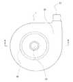
図1は、本発明の遠心式血液ポンプ装置の実施例の正面図である。図2は、図1に示した遠心式血液ポンプ装置の平面図である。図3は、図2の遠心式血液ポンプ装置のA−A線断面図である。図4は、図3の遠心式血液ポンプ装置のB−B線断面図(インペラは外観にて表す)である。図5は、図3の遠心式血液ポンプ装置のB−B線断面図よりインペラを取り外した状態を示す断面図である。図6は、図3の遠心式血液ポンプ装置のC−C線断面図よりインペラを取り外した状態を示す断面図である。図7は、図3の遠心式血液ポンプ装置におけるインペラの拡大断面図である。図8は、図7のD−D線断面図である。A centrifugal blood pump device of the present invention will be described with reference to an embodiment shown in the drawings.
FIG. 1 is a front view of an embodiment of a centrifugal blood pump apparatus according to the present invention. FIG. 2 is a plan view of the centrifugal blood pump apparatus shown in FIG. 3 is a cross-sectional view of the centrifugal blood pump device of FIG. 2 taken along line AA. FIG. 4 is a cross-sectional view of the centrifugal blood pump device of FIG. 3 taken along the line BB (the impeller is expressed in appearance). 5 is a cross-sectional view showing a state where the impeller is removed from the cross-sectional view taken along the line BB of the centrifugal blood pump device of FIG. 6 is a cross-sectional view showing a state in which the impeller is removed from the cross-sectional view taken along the line CC of the centrifugal blood pump device of FIG. 7 is an enlarged cross-sectional view of an impeller in the centrifugal blood pump device of FIG. 8 is a cross-sectional view taken along the line DD of FIG.
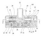
本発明の遠心式血液ポンプ装置1は、血液流入ポート22と血液流出ポート23とを有するハウジング20と、内部に第1の磁性体29と第2の磁性体(この実施例では永久磁石)25を備え、ハウジング20内で回転し、回転時の遠心力によって血液を送液するインペラ21を有する遠心ポンプ部2と、遠心ポンプ部2のインペラ21の第2の磁性体25を吸引するとともにインペラ21を回転させるためのインペラ回転トルク発生部3と、インペラ21の第1の磁性体29をインペラ回転トルク発生部3と反対側に磁気的吸引し、インペラ21をハウジング内にて浮上させた状態にて支持する非接触軸受機構(非接触軸受部)を備える遠心式血液ポンプ装置である。 The centrifugal blood pump apparatus 1 according to the present invention includes a
そして、インペラ21は、熱可塑性高分子材料により形成されたリング状のインペラ本体部材18と、熱可塑性高分子材料により形成され、かつ、インペラ本体部材18の一方の面に固定されるリング状のインペラ表面形成部材28とを備え、第1の磁性体29は、インペラ本体部材18とインペラ表面形成部材28間に移動不能に配置されており、さらに、インペラ本体部材18およびインペラ表面形成部材28は、環状外縁部および環状内縁部にて接触し、かつ環状外縁部および環状内縁部において融着されている。 The
図1ないし図8に示す実施例の遠心式血液ポンプ装置1は、非接触軸受機構が、インペラ21に設けられた第1の磁性体29と、第1の磁性体29をインペラ回転トルク発生部の吸引方向と反対側に吸引する磁性体もしくは電磁石(この実施例では、永久磁石41)と、インペラ回転トルク発生部側のハウジング内面もしくはインペラのインペラ回転トルク発生部側の表面に設けられた動圧溝38により構成されているタイプのものである。
具体的には、遠心式血液ポンプ装置1は、インペラ回転トルク発生部3は、インペラ21の第2の磁性体25を吸引するための磁石33を備えるロータ31と、ロータ31を回転させるモータ34を備えている。また、遠心ポンプ部内において、インペラ21に対するインペラ回転トルク発生部3の磁力発生源による吸引力と永久磁石41による吸引力の合力が、ハウジング20内のインペラ21の可動範囲の中央付近にて釣り合うものとなっている。また、インペラ回転トルク発生部側のハウジング内面もしくはインペラ21のインペラ回転トルク発生部側に設けられた第1の動圧溝38を備えている。さらに、この実施例のポンプ1のように、永久磁石41側のハウジング内面もしくはインペラ21の第1の磁性体29側の表面に設けられた第2の動圧溝71を備えることが好ましい。In the centrifugal blood pump device 1 of the embodiment shown in FIGS. 1 to 8, the non-contact bearing mechanism includes a first
Specifically, in the centrifugal blood pump device 1, the impeller rotational
図1ないし図5に示すように、この実施例の遠心式血液ポンプ装置1は、血液流入ポート22と血液流出ポート23を有するハウジング20と、ハウジング20内で回転し、回転時の遠心力によって血液を送液するインペラ21を有する遠心式血液ポンプ部2と、インペラ21のためのインペラ回転トルク発生部3と、インペラ21をインペラ回転トルク発生部3と反対方向に吸引するインペラ補助吸引部4を備える。
インペラ21は、図3に示すように、回転時に動圧溝38により発生する圧力により、ハウジング内面に接触することなく回転する。特に、このポンプ装置1では、永久磁石41によりインペラ21をロータと反対方向に吸引するため、通常の動圧溝により得られるインペラとハウジング間距離よりもさらに離間した状態にて回転する。As shown in FIGS. 1 to 5, the centrifugal blood pump apparatus 1 of this embodiment includes a
As shown in FIG. 3, the
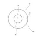
ハウジング20は、血液流入ポート22と血液流出ポート23とを備え、非磁性材料により形成されている。ハウジング20内には、血液流入ポート22および血液流出ポート23と連通する血液室24が形成されている。このハウジング20内には、インペラ21が収納されている。血液流入ポート22は、ハウジング20の上面の中央付近よりほぼ垂直に突出するように設けられている。なお、血液流入ポート22は、このようなストレート管に限定されるものでなく、湾曲管もしくは屈曲管でもよい。血液流出ポート23は、図2および図4に示すように、ほぼ円筒状に形成されたハウジング20の側面より接線方向に突出するように設けられている。図4に示すように、ハウジング20内に形成された血液室24内には、中央に貫通口21aを有する円板状のインペラ21が収納されている。なお、この実施例におけるハウジングでは、流出路は2つに区分されたダブルボリュート構造となっているが、シングルボリュート構造のもの、またボリュートがない構造のものでもよい。 The
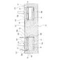
インペラ21は、図7に示すように、熱可塑性高分子材料により形成された平板リング状のインペラ本体部材18と、熱可塑性高分子材料により形成され、かつ、インペラ本体部材18の一方の面に固定されるリング状のインペラ表面形成部材28とを備える。特に、この実施例におけるインペラ21は、インペラ本体部材18の他方の面に固定される平板リング状の第2のインペラ表面形成部材27を備える。
そして、第1の磁性体29は、インペラ本体部材18とインペラ表面形成部材28間に移動不能に配置されている。また、インペラ本体部材18およびインペラ表面形成部材28は、環状外縁部および環状内縁部にて接触し、かつ環状外縁部および環状内縁部において融着されている。具体的には、図7および図8に示すように、インペラ本体部材18は、等角度に配置された複数(この実施例では7つ)のベーン形成部19aと、複数のベーン形成部19aの上部を連結する上部リング部19bと、複数のベーン形成部19aの下部を連結する下部リング部19cとを備えている。さらに、インペラ本体部材18は、上部側の環状外縁部18a、上部側の環状内縁部18b、下部側の環状外縁部18c、下部側の環状内縁部18dを備えている。この実施例では、各外縁部、各内縁部は、環状に突出する環状突出部となっている。As shown in FIG. 7, the
The first
インペラ表面形成部材28は、平板リング状部材となっており、インペラ本体部材18の上部側の環状外縁部18aと接触する環状外縁部28aと、インペラ本体部材18の上部側の環状内縁部18bと接触する環状内縁部28bを備えている。この実施例では、インペラ表面形成部材28の各外縁部および各内縁部は、インペラ本体部材18の各外縁部および各内縁部を収納可能な環状切欠部となっている。また、インペラ表面形成部材28は、第1の磁性体29の収納部を備えており、第1の磁性体29は、インペラ本体部材18とインペラ表面形成部材28間に移動不能に配置されている。なお、第1の磁性体収納部は、インペラ本体部材18に設けてもよく、また、インペラ表面形成部材28とインペラ本体部材18の両者に、配分して設けてもよい。 The impeller
第2のインペラ表面形成部材27は、平板リング状部材となっており、インペラ本体部材18の下部側の環状外縁部18cと接触する環状外縁部27aと、インペラ本体部材18の下部側の環状内縁部18dと接触する環状内縁部27bを備えている。この実施例では、インペラ表面形成部材27の各外縁部および各内縁部は、インペラ本体部材18の各外縁部および各内縁部を収納可能な環状切欠部となっている。また、インペラ表面形成部材27は、第2の磁性体25の収納部を備えており、第2の磁性体25は、インペラ本体部材18と第2のインペラ表面形成部材27間に移動不能に配置されている。なお、第2の磁性体収納部は、インペラ本体部材18に設けてもよく、また、第2のインペラ表面形成部材27とインペラ本体部材18の両者に、配分して設けてもよい。 The second impeller
そして、インペラ本体部材18、インペラ表面形成部材28、第2のインペラ表面形成部材27は、熱可塑性高分子材料により形成されている。熱可塑性高分子材料としては、ポリプロピレン、ポリアミド、ポリイミド、ポリエーテルイミド(PEI)、ポリエステル、フルオロ重合体、ポリフェニレンスルフィド(PPS)、ポリエーテルイミド(PEI)、ポリエーテルエーテルケトン(PEEK)、ポリエーテルケトンケトン(PEKK)などが使用される。特に、強度等の点より、ポリエーテルエーテルケトン(PEEK)が好ましい。また、インペラに使用される熱可塑性高分子材料は、比重が2.0以下であることが好ましい。
そして、インペラ本体部材18およびインペラ表面形成部材28は、環状外縁部および環状内縁部にて接触し、かつ環状外縁部および環状内縁部において融着されている。融着は、高周波融着、超音波融着、レーザー融着などの接着剤を用いない方法により行われていることが好ましい。特に、環状外縁部および環状内縁部は、レーザー溶着により融着されていることが好ましい。The
The
さらに、環状外縁部および環状内縁部には、特定波長のレーザー光を吸収し発熱する融着補助物質42,43が設けられ、かつ、少なくとも、インペラ表面形成部材28を形成する熱可塑性高分子材料は、上記の特定波長のレーザー光を透過するものであることが好ましい。なお、インペラ本体部材18を形成する熱可塑性高分子材料も、上記の特定波長のレーザー光を透過するものであってもよい。なお、融着補助物質42,43は、環状外縁部および環状内縁部における接触面の全体(例えば、インペラ本体部材18の上部側の環状外縁部18aとインペラ表面形成部材28の環状外縁部28aとの接触面全体、他の接触部も同様)に設けられていることが好ましい。 Furthermore, the annular outer edge portion and the annular inner edge portion are provided with fusion
また、この実施例のインペラ21では、インペラ本体部材18および第2のインペラ表面形成部材27は、環状外縁部および環状内縁部にて接触し、かつ環状外縁部および環状内縁部において融着されている。融着は、高周波融着、超音波融着、レーザー融着などの接着剤を用いない方法により行われていることが好ましい。特に、環状外縁部および環状内縁部は、レーザー溶着により融着されていることが好ましい。この実施例のインペラ21では、環状外縁部および環状内縁部には、特定波長のレーザー光を吸収し発熱する融着補助物質44,45が設けられ、かつ、少なくとも、第2のインペラ表面形成部材27を形成する熱可塑性高分子材料は、上記の特定波長のレーザー光を透過するものであることが好ましい。 Further, in the
そして、融着補助物質は、カーボンブラック、ダイヤモンドライクカーボンなどの炭素素材、金属粉末などのレーザー吸収物質が用いられる。特に、金属粉末ではなく、炭素素材を用いることにより、イオン化した金属の血液中への流出がなく好ましい。また、融着補助物質は、厚さが0.01〜5μmとなるように配置されていることが好ましい。ダイヤモンドライクカーボンを基材に配置する場合には、密着性を向上させるため、基材とダイヤモンドライクカーボン間に中間層を設けることが行われる。中間層としては、基板上に形成された金属材料による第1層と金属/炭素の混合傾斜層から構成され、このような中間層を形成することで、ダイヤモンドライクカーボンの内部応力が緩和され、基材との密着性は向上する。しかし、この場合、中間層に含まれた金属材料の一部が血液中に金属イオンとして溶出する可能性があるので、本発明で用いられる融着補助物質としては、中間層を持たない単層のダイヤモンドライクカーボンが最も望ましい。 As the fusion auxiliary substance, a carbon material such as carbon black or diamond-like carbon, or a laser absorbing substance such as metal powder is used. In particular, it is preferable to use a carbon material instead of a metal powder because the ionized metal does not flow out into the blood. Moreover, it is preferable that the fusion auxiliary substance is disposed so as to have a thickness of 0.01 to 5 μm. When diamond-like carbon is disposed on a substrate, an intermediate layer is provided between the substrate and diamond-like carbon in order to improve adhesion. The intermediate layer is composed of a first layer made of a metal material formed on the substrate and a mixed gradient layer of metal / carbon. By forming such an intermediate layer, the internal stress of diamond-like carbon is relaxed, Adhesion with the substrate is improved. However, in this case, since a part of the metal material contained in the intermediate layer may be eluted into the blood as metal ions, the fusion auxiliary substance used in the present invention is a single layer having no intermediate layer. The diamond-like carbon is most desirable.
第1の磁性体29としては、磁性ステンレス、永久磁石等が使用される。この実施例では、図4に示すように、第1の磁性体29は、永久磁石41の形状に対応するように、平板リング状のものとなっている。なお、第1の磁性体29は、複数の磁性体を等角度に配置することにより構成してもよい。
第2の磁性体25としては、永久磁石、磁性ステンレスなどが使用され、特に、永久磁石が好ましい。この実施例では、インペラ21には、複数(例えば、14〜24個)の第2の磁性体25(永久磁石、従動マグネット)が埋設されている。第2の磁性体25(永久磁石)は、インペラ回転トルク発生部3のロータ31に設けられた永久磁石33によりインペラ21を血液流入ポート22と反対側に吸引され、ロータとのカップリングおよび回転トルクをインペラ回転トルク発生部より伝達するために設けられている。また、この実施例のようにある程度の個数の磁性体25を埋設することにより、後述するロータ31との磁気的結合も十分に確保できる。As the first
As the second
そして、インペラ21は、図8に示すように、隣り合うベーン形成部19aにより仕切られた複数(7つ)の血液通路が形成されている。血液通路は、図8に示すように、インペラ21の中央開口と連通し、インペラ21の中央開口を始端とし、外周縁まで徐々に幅が広がるように延びている。言い換えれば、隣り合う血液通路間にベーン形成部19aが形成されている。なお、この実施例では、それぞれの血液通路およびそれぞれのベーン形成部19aは、等角度間隔にかつほぼ同じ形状に設けられている。 As shown in FIG. 8, the
次に、インペラ21の製造方法の一例を図24および図25を用いて説明する。図24は、本発明の遠心式血液ポンプ装置に用いられるインペラの製造方法を説明するための説明図である。図25は、本発明の遠心式血液ポンプ装置に用いられるインペラの製造方法を説明するための説明図である。
インペラを形成する部材の接合には、インペラ接合用収納体が用いられる。インペラ接合用収納体101は、インペラ本体部材18を収納可能な環状凹部およびインペラ本体部材18の中央開口を貫通可能な円柱突出部を備える筒状体である。また、融着対象のインペラ本体部材18およびインペラ表面形成部材28のいずれかの環状外縁部には、融着補助物質42が塗布される。特に、インペラ本体部材18の環状外縁部18aに融着補助物質42を塗布することが好ましい。同様に、融着対象のインペラ本体部材18およびインペラ表面形成部材28のいずれかの環状内縁部には、融着補助物質43が塗布される。特に、インペラ本体部材18の環状内縁部18bに融着補助物質43を塗布することが好ましい。融着補助物質42,43としては、特定波長のレーザー光を吸収し発熱する上述のものが好適に使用される。Next, an example of a method for manufacturing the
An impeller joint housing is used for joining the members forming the impeller. The impeller
そして、例えば、環状外縁部18aに融着補助物質42が塗布され、環状内縁部18bに融着補助物質43が塗布されたインペラ本体部材18をインペラ接合用収納体101の環状凹部の内に、融着補助物質塗布面が上方となるように収納する。そして、インペラ表面形成部材28を上記のインペラ本体部材18の上面に載置されるように、インペラ接合用収納体101に収納する。そして、インペラ表面形成部材28の上面に平板リング状の押圧板102を載置し、図24に、矢印で示す方向に押圧する。そして、この状態において、押圧板102とインペラ接合用収納体101間には、外縁側環状間隙113,内縁側環状間隙114が形成される。そして、外縁側環状間隙113に上述の融着補助物質が吸収する波長のレーザー光を照射可能なレーザープローブ103を挿入し、インペラ表面形成部材28の表面よりレーザーを照射する。インペラ表面形成部材28は、このレーザーを透過する材料にて形成されているため、レーザー光は、融着補助物質42に到達する。そして、融着補助物質42は、レーザー光を吸収することにより発熱し、インペラ本体部材18およびインペラ表面形成部材28の環状外縁部18a,28aを溶融する。そして、レーザープローブ103を外縁側環状間隙113内を摺動させることにより、インペラ本体部材18およびインペラ表面形成部材28の環状外縁部は、融着される。同様に、レーザープローブ104を用いて、インペラ本体部材18およびインペラ表面形成部材28の環状内縁部を融着する。また、インペラ本体部材18と第2のインペラ表面形成部材27の環状外縁部および環状内縁部も同様に融着される。これにより、インペラ21が形成される。 Then, for example, the
なお、上述したインペラ接合用収納体では、押圧板間にレーザープローブ挿入用の環状間隙が形成されるものとなっているが、押圧板として、融着補助物質が吸収する所定波長のレーザー光を透過する材料を用いる場合には、そのような間隙が形成されないものであってもよい。この場合、照射されるレーザー光は、押圧板およびインペラ表面形成部材の両者を透過した後、融着補助物質に到達するものとなる。
インペラ回転トルク発生部3は、図3に示すように、ハウジング20内に収納されたロータ31とロータ31を回転させるためのモータ34を備える。ロータ31は、血液ポンプ部2側の面に設けられた複数の永久磁石33を備える。ロータ31の中心は、モータ34の回転軸に固定されている。永久磁石33は、インペラ21の第2の磁性体(永久磁石)25の配置形態(数および配置位置)に対応するように、複数かつ等角度ごとに設けられている。また、ロータ31を回転駆動させるモータとしては、DCブラシレスモータを含む同期モータ、インダクションモータを含む非同期モータなどが使用されるが、モータの種類はどのようなものであってもよい。In the impeller bonding housing described above, an annular gap for inserting a laser probe is formed between the pressing plates. As the pressing plate, laser light having a predetermined wavelength absorbed by the fusion auxiliary substance is used. In the case of using a transparent material, such a gap may not be formed. In this case, the irradiated laser light passes through both the pressing plate and the impeller surface forming member, and then reaches the fusion auxiliary substance.
As shown in FIG. 3, the impeller rotational
インペラ補助吸引部4は、図2および図3に示すように、インペラの磁性体28を吸引するための固定された少なくとも1つの永久磁石41を備えている。具体的には、永久磁石41は、リング状のものが用いられている。また、リング状の永久磁石を同心的に複数配置してもよい。さらには、永久磁石41としては、複数の永久磁石を等角度間隔に配置したものでもよい。この場合、永久磁石の数としては、2〜8個が好ましく、特に、3〜6個が好ましい。この実施例では、永久磁石41を用いているが、第1の磁性体29をインペラ回転トルク発生部の吸引方向と反対側に吸引する磁性体もしくは電磁石としては、電磁石でもよく、さらには、第1の磁性体が、永久磁石であれば、強磁性体でもよい。 As shown in FIGS. 2 and 3, the impeller
さらに、この実施例の遠心式血液ポンプ装置1では、ハウジング20は、図3および図5に示すように、インペラ21を収納するとともに血液室24を形成するハウジング内面を備え、ロータ31側のハウジング内面20aに設けられた動圧溝38を備えている。そして、インペラ21は、所定以上の回転数にて回転することにより発生する動圧溝38とインペラ21間に形成される動圧軸受効果により、非接触状態にて回転する。
動圧溝38は、図5に示すように、インペラ21の底面(ロータ側面)に対応する大きさに形成されている。この実施例のポンプ装置1では、ハウジング内面20aの中心より若干離間した円形部分の周縁(円周)上に一端を有し、渦状に(言い換えれば、湾曲して)ハウジング内面20aの外縁付近まで、幅が徐々に広がるように延びている。また、動圧溝38は複数個設けられており、それぞれの動圧溝38はほぼ同じ形状であり、かつほぼ同じ間隔に配置されている。動圧溝38は、凹部であり、深さとしては、0.005〜0.4mm程度が好適である。動圧溝としては、6〜36個程度設けることが好ましい。この実施例では、12個の動圧溝がインペラの中心軸に対して等角度に配置されている。この実施例のポンプ装置における動圧溝38は、いわゆる内向スパイラル溝形状となっており、インペラが反時計方向に回転することにより、この動圧溝の作用による流体のポンピングは、溝部の外径から内径に向け圧力が高められるために、インペラ21とこの動圧溝を形成しているハウジング20間に反発力が得られ、これが動圧力となる。Further, in the centrifugal blood pump device 1 of this embodiment, the
As shown in FIG. 5, the
なお、動圧溝は、ハウジング側ではなくインペラ21のロータ側の面に設けてもよい。この場合も上述した動圧溝と同様の構成とすることが好ましい。
このような動圧溝を有するため、インペラ回転トルク発生部3側に吸引されるが、ハウジングの動圧溝38とインペラ21の底面間(もしくはインペラの動圧溝とハウジング内面間)に形成される動圧軸受効果により、若干であるが、ハウジング内面より離れ、非接触状態にて回転し、インペラの下面とハウジング内面間に血液流路を確保するため、両者間での血液滞留およびそれに起因する血栓の発生を防止する。さらに、通常状態において、動圧溝が、インペラの下面とハウジング内面間において撹拌作用を発揮するので、両者間における部分的な血液滞留の発生を防止する。
さらに、動圧溝38は、その角となる部分が少なくとも0.05mm以上のRを持つように丸められていることが好ましい。このようにすることにより、溶血の発生をより少ないものとすることができる。The dynamic pressure groove may be provided not on the housing side but on the rotor side surface of the
Since it has such a dynamic pressure groove, it is attracted to the impeller rotational
Furthermore, the
そして、遠心式血液ポンプ装置1は、永久磁石41側のハウジング内面もしくはインペラ21の永久磁石41側の表面に設けられた第2の動圧溝71を備えていることが好ましい。
具体的には、図3ないし図6に図示するように、ハウジング20は、インペラ21を収納するとともに血液室24を形成するハウジング内面を備え、ロータ31側のハウジング内面20aに設けられた第1の動圧溝38を備えるとともに、永久磁石41側のハウジング内面20bに設けられた第2の動圧溝71を備えている。
このため、インペラ21は、所定以上の回転数により回転することにより発生する第1の動圧溝38とインペラ21間に形成される動圧軸受効果により、非接触状態にて回転するとともに、外的衝撃を受けた時また第1の動圧溝38による動圧力が過剰となった時に、インペラのハウジング内面20b側への密着を防止する。そして、第1の動圧溝により発生する動圧力と第2の動圧溝により発生する動圧力は異なるものとなっていてもよい。The centrifugal blood pump device 1 preferably includes a second
Specifically, as shown in FIGS. 3 to 6, the
For this reason, the
インペラ21のインペラ表面形成部材28とハウジング内面20bとの隙間と、インペラ21の第2のインペラ表面形成部材27とハウジング内面20aとの隙間とをほぼ同じ状態でインペラ21は回転するのが望ましい。インペラ21に作用する流体力等の外乱が大きく、一方の隙間が狭くなる場合には、その狭くなる側に配した一方の動圧溝による動圧力を他方の動圧溝による動圧力より大きくし、両隙間をほぼ同じようにするため、各々溝形状を異なるようにすることが望ましい。インペラ21に作用する流体力等の外乱が小さい場合には、両動圧溝形状は同一であることが望ましい。 It is desirable for the
動圧溝71は、上述した動圧溝38と同様に、インペラ21の上面(永久磁石側面)に対応する大きさに形成されている。図3および図6に図示するポンプ装置1では、ハウジング内面20bの中心より若干離間した円形部分の周縁(円周)上に一端を有し、渦状に(言い換えれば、湾曲して)ハウジング内面20bの外縁付近まで、幅が徐々に広がるように延びている。特に、この実施例では、動圧溝は、途中で屈曲したいわゆるヘリングボーン形状となっている。また、動圧溝71は複数個設けられており、それぞれの動圧溝71はほぼ同じ形状であり、かつほぼ同じ間隔に配置されている。動圧溝71は、凹部であり、深さとしては、0.005〜0.4mm程度が好適である。動圧溝71としては、6〜36個程度設けることが好ましい。この実施例では、12個の動圧溝がインペラの中心軸に対して等角度に配置されている。
なお、第2の動圧溝は、ハウジング側ではなくインペラ21の永久磁石側の面に設けてもよい。この場合も上述した第2の動圧溝と同様の構成とすることが好ましい。さらに、動圧溝71は、その角となる部分が少なくとも0.05mm以上のRを持つように丸められていることが好ましい。このようにすることにより、溶血の発生をより少ないものとすることができる。The
The second dynamic pressure groove may be provided not on the housing side but on the surface of the
そして、本発明の遠心式血液ポンプ装置1では、第2の磁性体25と磁石33(インペラ回転トルク発生部3)間の吸引力(図3では下方への作用力)と、第1の磁性体29と永久磁石41間の吸引力(図3では上方への作用力)との合力は、インペラ21の可動範囲であるハウジング20のほぼ中央位置でゼロとなるように設定されていることが好ましい。このようにすることにより、インペラ21のいかなる可動範囲においてもインペラ21への吸引力による作用力は非常に小さい。その結果、インペラ21の回転起動時に発生するインペラ21とハウジング20との相対すべり時の摩擦抵抗を小さくできるために、相対すべり時における両部材表面の損傷(表面の凹凸)はほとんどなく、さらに低速回転時の動圧力が小さい場合にもインペラ21はハウジング20から非接触で浮上しやすくなる。そして、インペラ21とハウジング20との相対すべりによって溶血・血栓が発生する可能性もあり、またその相対すべり時に発生したわずかな表面損傷(凹凸)による血栓が発生する可能性もあるため、図1のようにインペラの両側から吸引力を作用させ、さらにそれらの吸引力を釣り合わせ、その合力を極限まで小さくすることでインペラ21とハウジング20間の接触圧力を低減させる方法は有効である。 In the centrifugal blood pump device 1 of the present invention, the attractive force (the downward acting force in FIG. 3) between the second
また、インペラ補助吸引部4は、インペラに設けられた磁性体29とハウジングに設けられた永久磁石41とにより構成されているが、これに限られるものではなく、インペラに永久磁石を設け、ハウジング側にその永久磁石との間において吸引力を発揮する磁性体を設けたものであってもよい。
また、インペラ補助吸引部4における磁性体29と永久磁石41の吸引力に起因するインペラの剛性低下を防ぐため、対向する磁性体と永久磁石とはその対向面のサイズが異なることが好ましい。永久磁石41は、磁性体28より小さいものとなっており、両者対向面のサイズが異なっている。これによって、両者間の距離によって変化する吸引力の変化量、すなわち負の剛性を小さく抑えることで、インペラ支持剛性の低下を防いでいる。Moreover, although the impeller auxiliary | assistant attraction |
Further, in order to prevent impeller rigidity from being lowered due to the attractive force of the
図5および図6の例では、2つの動圧溝は同じ形状としたが、各動圧溝の形状を変え、各動圧性能を変更してもよい。例えば、ポンピングの際に流体力などインペラ21に対して常に一方方向に外乱が作用する場合には、その外乱の方向にある動圧溝38の性能を他方の動圧溝71の性能より高めておくことで、インペラ21をハウジング20の中央位置で浮上回転できる結果、インペラ21とハウジング20との接触する確率を低く抑えることができ、安定したインペラの浮上性能を得ることができる。
図5には、内向スパイラル溝形状の動圧溝を示したが、この動圧溝形状はいかなるものであっても利用できる。
図6に示すように、この実施例における第2の動圧溝71は、いわゆるヘリングボーン形状となっている。インペラ21はこの動圧溝に対向して配置し、インペラ21はこの溝に対して、時計回りに回転することで、この動圧溝の作用による流体のポンピングはインペラ21の外径側および内径側からその中央部に向けポンピング流体の流れを作るように作用する。その結果、インペラ21とこの動圧溝を形成しているハウジング20間に反発力が得られこれが動圧力となる。動圧溝形状には種々あるが、血液ポンプとして利用するためには、ポンピング流体の流れがスムーズな内向スパイラル溝形状が好ましい。5 and 6, the two dynamic pressure grooves have the same shape, but the shape of each dynamic pressure groove may be changed to change each dynamic pressure performance. For example, when a disturbance is always applied in one direction to the
Although FIG. 5 shows a dynamic pressure groove having an inward spiral groove shape, this dynamic pressure groove shape may be any shape.
As shown in FIG. 6, the second
次に、図9ないし図13に示す実施例の遠心式血液ポンプ装置100について、説明する。
図9は、本発明の遠心式血液ポンプ装置の他の実施例の平面図である。図10は、図9の遠心式血液ポンプ装置のE−E線断面図である。図11は、図10の遠心式血液ポンプ装置のF−F線断面図(インペラは外観にて表す)である。図12は、図10の遠心式血液ポンプ装置におけるインペラの拡大断面図である。図13は、図12のG−G線断面図である。
この実施例の遠心式血液ポンプ装置100と上述した実施例の遠心式血液ポンプ装置1との相違は、非接触軸受機構のみであり、その他は同じであり、上述した説明を参照するものとする。Next, the centrifugal
FIG. 9 is a plan view of another embodiment of the centrifugal blood pump device of the present invention. 10 is a cross-sectional view of the centrifugal blood pump device of FIG. 9 taken along the line EE. FIG. 11 is a cross-sectional view of the centrifugal blood pump apparatus of FIG. 10 taken along the line F-F (the impeller is expressed in appearance). 12 is an enlarged cross-sectional view of an impeller in the centrifugal blood pump device of FIG. 13 is a cross-sectional view taken along the line GG in FIG.
The difference between the centrifugal
この実施例の遠心式血液ポンプ装置100では、非接触軸受機構が、インペラ21に設けられた第1の磁性体29および第3の磁性体46と、第1の磁性体29をインペラ回転トルク発生部3の吸引方向と反対側に吸引する永久磁石41と、第3の磁性体46をインペラ回転トルク発生部の吸引方向に吸引する電磁石47により構成されている。また、この遠心式血液ポンプ装置100においても、インペラ回転トルク発生部側のハウジング内面もしくはインペラのインペラ回転トルク発生部側の表面に設けられた動圧溝38が設けられている。
そして、この遠心式血液ポンプ装置100に用いられるインペラ21は、図12に示すように、インペラ本体部材18の他方の面に固定されるリング状の第2のインペラ表面形成部材27を備え、第2の磁性体25および第3の磁性体46は、インペラ本体部材18と第2のインペラ表面形成部材27間に移動不能に配置されている。そして、上述したインペラ21と同様に、このインペラもインペラ本体部材18および第2のインペラ表面形成部材27は、環状外縁部および環状内縁部にて接触しかつ環状外縁部および環状内縁部において融着されている。In the centrifugal
The
インペラ21は、図12および図13に示すように、熱可塑性高分子材料により形成された平板リング状のインペラ本体部材18と、熱可塑性高分子材料により形成され、かつ、インペラ本体部材18の一方の面に固定されるリング状のインペラ表面形成部材28とを備える。特に、この実施例におけるインペラ21は、インペラ本体部材18の他方の面に固定される平板リング状の第2のインペラ表面形成部材27を備える。
そして、第1の磁性体29は、インペラ本体部材18とインペラ表面形成部材28間に移動不能に配置されている。また、インペラ本体部材18およびインペラ表面形成部材28は、環状外縁部および環状内縁部にて接触し、かつ環状外縁部および環状内縁部において融着されている。具体的には、図12および図13に示すように、インペラ本体部材18は、等角度に配置された複数(この実施例では7つ)のベーン形成部19aと、複数のベーン形成部19aの上部を連結する上部リング部19bと、複数のベーン形成部19aの下部を連結する下部リング部19cとを備えている。さらに、インペラ本体部材18は、上部側の環状外縁部18a、上部側の環状内縁部18b、下部側の環状外縁部18c、下部側の環状内縁部18dを備えている。この実施例では、各外縁部、各内縁部は、環状に突出する環状突出部となっている。As shown in FIGS. 12 and 13, the
The first
インペラ表面形成部材28は、平板リング状部材となっており、インペラ本体部材18の上部側の環状外縁部18aと接触する環状外縁部28aと、インペラ本体部材18の上部側の環状内縁部18bと接触する環状内縁部28bを備えている。この実施例では、インペラ表面形成部材28の各外縁部および各内縁部は、インペラ本体部材18の各外縁部および各内縁部を収納可能な環状切欠部となっている。また、インペラ表面形成部材28は、第1の磁性体29の収納部を備えており、第1の磁性体29は、インペラ本体部材18とインペラ表面形成部材28間に移動不能に配置されている。なお、第1の磁性体収納部は、インペラ本体部材18に設けてもよく、また、インペラ表面形成部材28とインペラ本体部材18の両者に、配分して設けてもよい。 The impeller
第2のインペラ表面形成部材27は、平板リング状部材となっており、インペラ本体部材18の下部側の環状外縁部18cと接触する環状外縁部27aと、インペラ本体部材18の下部側の環状内縁部18dと接触する環状内縁部27bを備えている。この実施例では、インペラ表面形成部材27の各外縁部および各内縁部は、インペラ本体部材18の各外縁部および各内縁部を収納可能な環状切欠部となっている。また、インペラ表面形成部材27は、第2の磁性体25の収納部および第3の磁性体46の収納部を備えており、第2の磁性体25,第3の磁性体46は、インペラ本体部材18と第2のインペラ表面形成部材27間に移動不能に配置されている。なお、第2の磁性体収納部および第3の磁性体46の収納部は、インペラ本体部材18に設けてもよく、また、第2のインペラ表面形成部材27とインペラ本体部材18の両者に、配分して設けてもよい。 The second impeller
そして、インペラ本体部材18、インペラ表面形成部材28、第2のインペラ表面形成部材27は、熱可塑性高分子材料により形成されている。熱可塑性高分子材料としては、上述した通りである。そして、インペラ本体部材18およびインペラ表面形成部材28は、環状外縁部および環状内縁部にて接触し、かつ環状外縁部および環状内縁部において融着されている。同様に、インペラ本体部材18およびインペラ表面形成部材27は、環状外縁部および環状内縁部にて接触し、かつ環状外縁部および環状内縁部において融着されている。融着方法等についても上述した方法が用いられる。
この実施例の遠心式血液ポンプ装置100では、第3の磁性体46を吸引する電磁石47を備えるものの、インペラ回転トルク発生部と同じ側に配置することにより、ポンプ軸長を小さくし、ポンプ装置を小型化することができる。そして、この遠心式血液ポンプ装置100では、第2の磁性体25と永久磁石33間の吸引力と、第3の磁性体46と電磁石47間の吸引力と、第1の磁性体29と永久磁石41間の吸引力とが釣り合うように、電磁石47に流れる電流を制御して、インペラ21を血液室24の中心に保持することにより、インペラを非接触軸受するものである。The
Although the centrifugal
そして、電磁石47は、ロータの中心軸に対して、等角度間隔となるように複数(具体的には3つ)設けられている。さらに、また、この実施例の遠心式血液ポンプ装置100では、複数の位置センサ48も、ロータの中心軸に対して、等角度間隔となるように複数設けられている。位置センサ48は磁気式センサが使用され、3個以上が好ましい。この遠心式血液ポンプ装置100では、位置センサ48の検出結果を用いて、電磁石47を制御することにより、インペラ21の回転軸方向(Z方向)の力を釣りあわせ、かつ回転軸(Z軸)に直交するX軸とY軸周りのモーメントを制御している。 A plurality (specifically, three) of
次に、図14ないし図20に示す実施例の遠心式血液ポンプ装置200について、説明する。
図14は、本発明の遠心式血液ポンプ装置の他の実施例の正面図である。図15は、図14に示した遠心式血液ポンプ装置の平面図である。図16は、図15の遠心式血液ポンプ装置のH−H線断面図である。図17は、図16の遠心式血液ポンプ装置のI−I線断面図(インペラは外観にて表す)である。図18は、図16の遠心式血液ポンプ装置におけるインペラの拡大断面図である。図19は、図18のインペラよりインペラ表面形成部材を取り外した状態の外観図である。図20は、図18のインペラよりインペラ表面形成部材を取り外した状態のインペラの外観図である。図20は、図18のJ−J線断面図である。
この実施例の遠心式血液ポンプ装置200と上述した実施例の遠心式血液ポンプ装置1との相違は、非接触軸受機構のみであり、その他は同じであり、上述した説明を参照するものとする。Next, the centrifugal
FIG. 14 is a front view of another embodiment of the centrifugal blood pump device of the present invention. 15 is a plan view of the centrifugal blood pump device shown in FIG. 16 is a cross-sectional view of the centrifugal blood pump device of FIG. 15 taken along the line HH. FIG. 17 is a cross-sectional view taken along the line II of the centrifugal blood pump device of FIG. 16 (the impeller is expressed in appearance). 18 is an enlarged cross-sectional view of an impeller in the centrifugal blood pump apparatus of FIG. FIG. 19 is an external view of a state in which the impeller surface forming member is removed from the impeller of FIG. 20 is an external view of the impeller with the impeller surface forming member removed from the impeller of FIG. 20 is a cross-sectional view taken along line JJ in FIG.
The difference between the centrifugal
この実施例の遠心式血液ポンプ装置200では、非接触軸受機構が、インペラ21に設けられた第1の磁性体29と、インペラ21の第1の磁性体29をインペラ回転トルク発生部の吸引方向と反対側に吸引する電磁石49により構成されている。
非接触軸受機構として、図15および図16に示すように、インペラの第1の磁性体29を吸引するための固定された複数の電磁石49と、インペラの第1の磁性体29の位置を検出するための位置センサ48を備えている。具体的には、インペラ位置制御部4は、ハウジング20内に収納された複数の電磁石49と、複数の位置センサ48を有する。インペラ位置制御部の複数(3つ)の電磁石49および複数(3つ)の位置センサ48は、それぞれ等角度間隔にて設けられており、電磁石49と位置センサ48も等角度間隔にて設けられている。電磁石49は、鉄心とコイルからなる。電磁石49は、この実施例では、3個設けられている。電磁石49は、3個以上、例えば、4つでもよい。3個以上設け、これらの電磁力を位置センサ48の検知結果を用いて調整することにより、インペラ21の回転軸(Z軸)方向の力を釣り合わせ、かつ回転軸(Z軸)に直交するX軸およびY軸まわりのモーメントを制御することができる。In the centrifugal
As a non-contact bearing mechanism, as shown in FIG. 15 and FIG. 16, a plurality of fixed
位置センサ48は、電磁石49と磁性体29との隙間の間隔を検知し、この検知出力は、電磁石49のコイルに与えられる電流もしくは電圧を制御する制御機構(図示せず)に送られる。また、インペラ21に重力等による半径方向の力が作用しても、インペラ21の第2の磁性体25とロータ31の永久磁石33との間の磁束の剪断力および電磁石49と磁性体29との間の磁束の剪断力が作用するため、インペラ21はハウジング20の中心に保持される。
そして、この遠心式血液ポンプ装置200に用いられるインペラ21は、図18ないし図20に示すように、熱可塑性高分子材料により形成された平板リング状のインペラ本体部材18と、熱可塑性高分子材料により形成され、かつ、インペラ本体部材18の一方の面に固定されるリング状のインペラ表面形成部材28とを備える。さらに、この実施例におけるインペラ21は、インペラ本体部材18の他方の面に固定される平板リング状の第2のインペラ表面形成部材27を備える。そして、第1の磁性体29は、図19に示すように、幅の広い平板リング状のものが用いられている。The
As shown in FIGS. 18 to 20, the
そして、第1の磁性体29は、インペラ本体部材18とインペラ表面形成部材28間に移動不能に配置されている。このインペラ21では、インペラ本体部材18の上面に設けられた環状凹部と、インペラ表面形成部材28の下面に設けられた環状凹部により、第1の磁性体29の収納部が形成されている。また、インペラ本体部材18およびインペラ表面形成部材28は、環状外縁部および環状内縁部にて接触し、かつ環状外縁部および環状内縁部において融着されている。具体的には、図18および図20に示すように、インペラ本体部材18は、等角度に配置された複数(この実施例では7つ)のベーン形成部19aと、複数のベーン形成部19aの上部を連結する上部リング部19bと、複数のベーン形成部19aの下部を連結する下部リング部19cとを備えている。さらに、インペラ本体部材18は、上部側の環状外縁部18a、上部側の環状内縁部18b、下部側の環状外縁部18c、下部側の環状内縁部18dを備えている。この実施例では、各外縁部、各内縁部は、環状に突出する環状突出部となっている。 The first
インペラ表面形成部材28は、平板リング状部材となっており、インペラ本体部材18の上部側の環状外縁部18aと接触する環状外縁部28aと、インペラ本体部材18の上部側の環状内縁部18bと接触する環状内縁部28bを備えている。この実施例では、インペラ表面形成部材28の各外縁部および各内縁部は、インペラ本体部材18の各外縁部および各内縁部と当接可能な環状突出部となっている。
第2のインペラ表面形成部材27は、平板リング状部材となっており、インペラ本体部材18の下部側の環状外縁部18cと接触する環状外縁部27aと、インペラ本体部材18の下部側の環状内縁部18dと接触する環状内縁部27bを備えている。この実施例では、インペラ表面形成部材27の各外縁部および各内縁部は、インペラ本体部材18の各外縁部および各内縁部を収納可能な環状切欠部となっている。また、インペラ表面形成部材27は、第2の磁性体25の収納部を備えており、第1の磁性体29は、インペラ本体部材18と第2のインペラ表面形成部材27間に移動不能に配置されている。なお、第2の磁性体収納部は、インペラ本体部材18に設けてもよく、また、第2のインペラ表面形成部材27とインペラ本体部材18の両者に、配分して設けてもよい。The impeller
The second impeller
そして、インペラ本体部材18、インペラ表面形成部材28、第2のインペラ表面形成部材27は、熱可塑性高分子材料により形成されている。熱可塑性高分子材料としては、上述した通りである。そして、インペラ本体部材18およびインペラ表面形成部材28は、環状外縁部および環状内縁部にて接触し、かつ環状外縁部および環状内縁部において融着されている。同様に、インペラ本体部材18およびインペラ表面形成部材27は、環状外縁部および環状内縁部にて接触し、かつ環状外縁部および環状内縁部において融着されている。融着方法等についても上述した方法が用いられる。 The
また、上述の実施例のポンプ装置では、インペラ回転トルク発生部は、ロータとモータとを備えるものであるが、上述したすべての実施例において、例えば、図21ないし図23に示すように、ステーターコイルを用いるものであってもよい。
言い換えれば、上述したポンプ装置では、インペラ回転トルク発生部は、前記インペラの第2の磁性体を吸引するための磁石を備えるロータと、ロータを回転させるモータとを備えるものとなっている。これに対して、図21ないし図23に示すポンプ装置300では、インペラ回転トルク発生部は、インペラの第2の磁性体を吸引するとともにインペラを回転させるために円周上に配置された複数のステーターコイルを備えるものとなっている。In the pump device of the above-described embodiment, the impeller rotational torque generating unit includes a rotor and a motor. In all of the above-described embodiments, for example, as shown in FIGS. A coil may be used.
In other words, in the pump device described above, the impeller rotational torque generating unit includes a rotor including a magnet for attracting the second magnetic body of the impeller and a motor for rotating the rotor. On the other hand, in the
図21は、本発明の遠心式血液ポンプ装置の他の実施例の断面図である。図22は、図21の遠心式血液ポンプ装置のK−K線断面図(インペラは外観にて表す)である。図23は、図21の遠心式血液ポンプ装置の底面図である。なお、図21に示した実施例の遠心式血液ポンプ装置の平面図は、図15と同じであるのでそれらを参照する。
この実施例のポンプ装置300と上述したポンプ装置200との相違は、インペラ回転トルク発生部3の機構のみである。このポンプ装置300では、遠心ポンプ部2のインペラ21の第2の磁性体25を吸引するとともにインペラ21を回転させるために円周上に配置された複数のステーターコイル91を備えるインペラ回転トルク発生部3を有している。FIG. 21 is a cross-sectional view of another embodiment of the centrifugal blood pump device of the present invention. 22 is a cross-sectional view of the centrifugal blood pump device of FIG. 21 taken along the line KK (the impeller is represented by the appearance). 23 is a bottom view of the centrifugal blood pump device of FIG. In addition, since the top view of the centrifugal blood pump apparatus of the Example shown in FIG. 21 is the same as FIG. 15, they are referred.
The difference between the
この実施例のポンプ装置300と上述した実施例のポンプ装置1との実質的な相違は、インペラ回転トルク発生部3の機構のみである。この実施例のポンプ装置300におけるインペラ回転トルク発生部3では、いわゆるロータを備えず、直接インペラを駆動するタイプとなっている。
また、この実施例のように、インペラ内には、ある程度の個数の第2の磁性体25を埋設することにより、ステーターコイル91との磁気的結合も十分に確保できる。磁性体25(永久磁石)の形状としては、略台形状であることが好ましい。磁性体25は、リング状、板状のいずれでもよい。また、磁性体25の数および配置形態は、ステーターコイルの数および配置形態に対応していることが好ましい。複数の磁性体25は、磁極が交互に異なるように、かつ、インペラの中心軸に対してほぼ等角度となるように円周上に配置されている。The substantial difference between the
Further, as in this embodiment, by embedding a certain number of second
インペラ回転トルク発生部3は、図22および図23に示すように、ハウジング20内に収納された複数のステーターコイル91を備える。ステーターコイル91は、円周上にほぼその円周の中心軸に対して等角度となるように複数配置されている。具体的には、6個のステーターコイルが用いられている。また、ステーターコイルとしては、多層巻きのステーターコイルが用いられる。各ステーターコイル91に流れる電流の方向を切り換えることにより、回転磁界が発生し、この回転磁界により、インペラは吸引されるとともに回転する。
そして、このようなステーターコイルを用いるタイプのポンプ装置においても、上述した実施例のポンプ装置1、100、200とインペラの回転駆動システム以外は同じであってもよい。As shown in FIGS. 22 and 23, the impeller rotational
Even in a pump device using such a stator coil, the
1 遠心式血液ポンプ装置
2 液体ポンプ部
3 インペラ回転トルク発生部
18 インペラ本体部材
21 インペラ
25 第2の磁性体
27 第2のインペラ表面形成部材
28 インペラ表面形成部材
29 第1の磁性体
31 ロータ
34 モータ
41 永久磁石
20 ハウジングDESCRIPTION OF SYMBOLS 1 Centrifugal
Claims (15)
Translated fromJapanese前記遠心ポンプ部の前記インペラの第2の磁性体を吸引するとともに該インペラを回転させるためのインペラ回転トルク発生部と、前記インペラの第1の磁性体を前記インペラ回転トルク発生部と反対側に磁気的吸引し、前記インペラを前記ハウジング内にて浮上させた状態にて支持する非接触軸受機構を備える遠心式血液ポンプ装置であって、
前記インペラは、熱可塑性高分子材料により形成されたリング状のインペラ本体部材と、熱可塑性高分子材料により形成され、かつ、前記インペラ本体部材の一方の面に固定されるリング状インペラ表面形成部材とを備え、前記第1の磁性体は、前記インペラ本体部材と前記インペラ表面形成部材間に移動不能に配置されており、さらに、前記インペラ本体部材および前記インペラ表面形成部材は、環状外縁部および環状内縁部にて接触しかつ該環状外縁部および環状内縁部において融着されていることを特徴とする遠心式血液ポンプ装置。A housing having a blood inflow port and a blood outflow port, and a first magnetic body and a second magnetic body inside, and an impeller that rotates within the housing and that feeds blood by centrifugal force during rotation A centrifugal pump unit;
An impeller rotational torque generating unit for attracting the second magnetic body of the impeller of the centrifugal pump unit and rotating the impeller, and a first magnetic body of the impeller on the side opposite to the impeller rotational torque generating unit A centrifugal blood pump device comprising a non-contact bearing mechanism for magnetically attracting and supporting the impeller in a floating state in the housing,
The impeller includes a ring-shaped impeller body member formed of a thermoplastic polymer material, and a ring-shaped impeller surface forming member formed of a thermoplastic polymer material and fixed to one surface of the impeller body member. The first magnetic body is disposed so as to be immovable between the impeller body member and the impeller surface forming member, and the impeller body member and the impeller surface forming member include an annular outer edge portion and A centrifugal blood pump device, wherein the centrifugal blood pump device contacts at an annular inner edge and is fused at the annular outer edge and the annular inner edge.
The said impeller rotational torque generation part is provided with the several stator coil arrange | positioned on the circumference in order to attract | suck the 2nd magnetic body of the said impeller and to rotate this impeller. A centrifugal blood pump device according to claim 1.
Priority Applications (1)
| Application Number | Priority Date | Filing Date | Title |
|---|---|---|---|
| JP2005286600AJP4472611B2 (en) | 2005-09-30 | 2005-09-30 | Centrifugal blood pump device |
Applications Claiming Priority (1)
| Application Number | Priority Date | Filing Date | Title |
|---|---|---|---|
| JP2005286600AJP4472611B2 (en) | 2005-09-30 | 2005-09-30 | Centrifugal blood pump device |
Publications (2)
| Publication Number | Publication Date |
|---|---|
| JP2007089973Atrue JP2007089973A (en) | 2007-04-12 |
| JP4472611B2 JP4472611B2 (en) | 2010-06-02 |
Family
ID=37976307
Family Applications (1)
| Application Number | Title | Priority Date | Filing Date |
|---|---|---|---|
| JP2005286600AExpired - Fee RelatedJP4472611B2 (en) | 2005-09-30 | 2005-09-30 | Centrifugal blood pump device |
Country Status (1)
| Country | Link |
|---|---|
| JP (1) | JP4472611B2 (en) |
Cited By (11)
| Publication number | Priority date | Publication date | Assignee | Title |
|---|---|---|---|---|
| WO2016047331A1 (en)* | 2014-09-24 | 2016-03-31 | テルモ株式会社 | Method for manufacturing centrifugal pump |
| CN108578802A (en)* | 2018-04-24 | 2018-09-28 | 苏州心擎医疗技术有限公司 | The quick fixation of blood pump and unlocking mechanism |
| US10722631B2 (en) | 2018-02-01 | 2020-07-28 | Shifamed Holdings, Llc | Intravascular blood pumps and methods of use and manufacture |
| US11185677B2 (en) | 2017-06-07 | 2021-11-30 | Shifamed Holdings, Llc | Intravascular fluid movement devices, systems, and methods of use |
| US11511103B2 (en) | 2017-11-13 | 2022-11-29 | Shifamed Holdings, Llc | Intravascular fluid movement devices, systems, and methods of use |
| US11964145B2 (en) | 2019-07-12 | 2024-04-23 | Shifamed Holdings, Llc | Intravascular blood pumps and methods of manufacture and use |
| US12102815B2 (en) | 2019-09-25 | 2024-10-01 | Shifamed Holdings, Llc | Catheter blood pumps and collapsible pump housings |
| US12121713B2 (en) | 2019-09-25 | 2024-10-22 | Shifamed Holdings, Llc | Catheter blood pumps and collapsible blood conduits |
| US12161857B2 (en) | 2018-07-31 | 2024-12-10 | Shifamed Holdings, Llc | Intravascular blood pumps and methods of use |
| US12220570B2 (en) | 2018-10-05 | 2025-02-11 | Shifamed Holdings, Llc | Intravascular blood pumps and methods of use |
| US12409310B2 (en) | 2019-12-11 | 2025-09-09 | Shifamed Holdings, Llc | Descending aorta and vena cava blood pumps |
- 2005
- 2005-09-30JPJP2005286600Apatent/JP4472611B2/ennot_activeExpired - Fee Related
Cited By (17)
| Publication number | Priority date | Publication date | Assignee | Title |
|---|---|---|---|---|
| JPWO2016047331A1 (en)* | 2014-09-24 | 2017-04-27 | テルモ株式会社 | Manufacturing method of centrifugal pump |
| JP2018028322A (en)* | 2014-09-24 | 2018-02-22 | テルモ株式会社 | Manufacturing method of centrifugal pump |
| WO2016047331A1 (en)* | 2014-09-24 | 2016-03-31 | テルモ株式会社 | Method for manufacturing centrifugal pump |
| US10851802B2 (en) | 2014-09-24 | 2020-12-01 | Terumo Kabushiki Kaisha | Method of manufacturing centrifugal pump |
| US11185677B2 (en) | 2017-06-07 | 2021-11-30 | Shifamed Holdings, Llc | Intravascular fluid movement devices, systems, and methods of use |
| US11511103B2 (en) | 2017-11-13 | 2022-11-29 | Shifamed Holdings, Llc | Intravascular fluid movement devices, systems, and methods of use |
| US10722631B2 (en) | 2018-02-01 | 2020-07-28 | Shifamed Holdings, Llc | Intravascular blood pumps and methods of use and manufacture |
| US11229784B2 (en) | 2018-02-01 | 2022-01-25 | Shifamed Holdings, Llc | Intravascular blood pumps and methods of use and manufacture |
| US12076545B2 (en) | 2018-02-01 | 2024-09-03 | Shifamed Holdings, Llc | Intravascular blood pumps and methods of use and manufacture |
| CN108578802A (en)* | 2018-04-24 | 2018-09-28 | 苏州心擎医疗技术有限公司 | The quick fixation of blood pump and unlocking mechanism |
| CN108578802B (en)* | 2018-04-24 | 2023-04-25 | 苏州心擎医疗技术有限公司 | Quick fixing and unlocking mechanism of blood pump |
| US12161857B2 (en) | 2018-07-31 | 2024-12-10 | Shifamed Holdings, Llc | Intravascular blood pumps and methods of use |
| US12220570B2 (en) | 2018-10-05 | 2025-02-11 | Shifamed Holdings, Llc | Intravascular blood pumps and methods of use |
| US11964145B2 (en) | 2019-07-12 | 2024-04-23 | Shifamed Holdings, Llc | Intravascular blood pumps and methods of manufacture and use |
| US12102815B2 (en) | 2019-09-25 | 2024-10-01 | Shifamed Holdings, Llc | Catheter blood pumps and collapsible pump housings |
| US12121713B2 (en) | 2019-09-25 | 2024-10-22 | Shifamed Holdings, Llc | Catheter blood pumps and collapsible blood conduits |
| US12409310B2 (en) | 2019-12-11 | 2025-09-09 | Shifamed Holdings, Llc | Descending aorta and vena cava blood pumps |
Also Published As
| Publication number | Publication date |
|---|---|
| JP4472611B2 (en) | 2010-06-02 |
Similar Documents
| Publication | Publication Date | Title |
|---|---|---|
| JP4472610B2 (en) | Centrifugal blood pump device | |
| CN102239334B (en) | Centrifugal pump device | |
| JP5656835B2 (en) | Rotation drive device and centrifugal pump device using the same | |
| JP4767488B2 (en) | Magnetic levitation pump | |
| US6641378B2 (en) | Pump with electrodynamically supported impeller | |
| JP4472612B2 (en) | Centrifugal blood pump device | |
| US9133847B2 (en) | Disposable magnetically-levitated centrifugal pump | |
| JP5681403B2 (en) | Centrifugal pump device | |
| JP5577506B2 (en) | Centrifugal pump device | |
| JP5171953B2 (en) | Blood pump device | |
| WO2011118325A1 (en) | Centrifugal blood pump device | |
| JP2004209240A (en) | Centrifugal type blood pump apparatus | |
| JP6083929B2 (en) | Centrifugal pump device | |
| JP4340183B2 (en) | Centrifugal blood pump device | |
| JP4472611B2 (en) | Centrifugal blood pump device | |
| JP2008132131A (en) | Sensorless magnetic bearing type blood pump apparatus | |
| JP2006167173A (en) | Centrifugal type blood pump apparatus | |
| JP6434423B2 (en) | Centrifugal pump system | |
| US7598643B2 (en) | Motor with electrodynamically and hydrodynamically supported rotor | |
| JP2010041742A (en) | Axially levitated rotating motor, and turbo-type pump using axially levitated rotating motor | |
| JP4340182B2 (en) | Blood pump device | |
| JP2012013043A (en) | Rotary drive device and centrifugal pump device using the same | |
| JP2020156178A (en) | Rotary driving device, and pump driving device |
Legal Events
| Date | Code | Title | Description |
|---|---|---|---|
| A621 | Written request for application examination | Free format text:JAPANESE INTERMEDIATE CODE: A621 Effective date:20080916 | |
| A977 | Report on retrieval | Free format text:JAPANESE INTERMEDIATE CODE: A971007 Effective date:20090902 | |
| A131 | Notification of reasons for refusal | Free format text:JAPANESE INTERMEDIATE CODE: A131 Effective date:20090915 | |
| A521 | Written amendment | Free format text:JAPANESE INTERMEDIATE CODE: A523 Effective date:20091112 | |
| A521 | Written amendment | Free format text:JAPANESE INTERMEDIATE CODE: A523 Effective date:20091113 | |
| TRDD | Decision of grant or rejection written | ||
| A01 | Written decision to grant a patent or to grant a registration (utility model) | Free format text:JAPANESE INTERMEDIATE CODE: A01 Effective date:20100209 | |
| A01 | Written decision to grant a patent or to grant a registration (utility model) | Free format text:JAPANESE INTERMEDIATE CODE: A01 | |
| A61 | First payment of annual fees (during grant procedure) | Free format text:JAPANESE INTERMEDIATE CODE: A61 Effective date:20100303 | |
| FPAY | Renewal fee payment (event date is renewal date of database) | Free format text:PAYMENT UNTIL: 20130312 Year of fee payment:3 | |
| R150 | Certificate of patent or registration of utility model | Free format text:JAPANESE INTERMEDIATE CODE: R150 | |
| FPAY | Renewal fee payment (event date is renewal date of database) | Free format text:PAYMENT UNTIL: 20130312 Year of fee payment:3 | |
| FPAY | Renewal fee payment (event date is renewal date of database) | Free format text:PAYMENT UNTIL: 20140312 Year of fee payment:4 | |
| R250 | Receipt of annual fees | Free format text:JAPANESE INTERMEDIATE CODE: R250 | |
| LAPS | Cancellation because of no payment of annual fees |