JP2007089764A - Electronic endoscope - Google Patents
Electronic endoscopeDownload PDFInfo
- Publication number
- JP2007089764A JP2007089764AJP2005282046AJP2005282046AJP2007089764AJP 2007089764 AJP2007089764 AJP 2007089764AJP 2005282046 AJP2005282046 AJP 2005282046AJP 2005282046 AJP2005282046 AJP 2005282046AJP 2007089764 AJP2007089764 AJP 2007089764A
- Authority
- JP
- Japan
- Prior art keywords
- cover glass
- electronic endoscope
- prism
- heater
- ccd
- Prior art date
- Legal status (The legal status is an assumption and is not a legal conclusion. Google has not performed a legal analysis and makes no representation as to the accuracy of the status listed.)
- Granted
Links
- 239000006059cover glassSubstances0.000claimsabstractdescription52
- 238000003384imaging methodMethods0.000claimsdescription39
- 230000003287optical effectEffects0.000claimsdescription24
- 238000010438heat treatmentMethods0.000claimsdescription14
- 230000005494condensationEffects0.000abstractdescription12
- 238000009833condensationMethods0.000abstractdescription12
- XLYOFNOQVPJJNP-UHFFFAOYSA-NwaterSubstancesOXLYOFNOQVPJJNP-UHFFFAOYSA-N0.000abstractdescription11
- 239000007787solidSubstances0.000abstract1
- 238000005406washingMethods0.000abstract1
- 238000003780insertionMethods0.000description18
- 230000037431insertionEffects0.000description18
- 238000004140cleaningMethods0.000description7
- 125000006850spacer groupChemical group0.000description6
- 239000000853adhesiveSubstances0.000description4
- 230000001070adhesive effectEffects0.000description4
- 238000005286illuminationMethods0.000description4
- 230000002093peripheral effectEffects0.000description4
- 238000005452bendingMethods0.000description3
- 239000003795chemical substances by applicationSubstances0.000description3
- 238000004519manufacturing processMethods0.000description3
- 238000007789sealingMethods0.000description3
- 230000036760body temperatureEffects0.000description2
- 230000001276controlling effectEffects0.000description2
- 230000002596correlated effectEffects0.000description2
- 238000000034methodMethods0.000description2
- 238000005070samplingMethods0.000description2
- 239000000758substrateSubstances0.000description2
- BQCADISMDOOEFD-UHFFFAOYSA-NSilverChemical compound[Ag]BQCADISMDOOEFD-UHFFFAOYSA-N0.000description1
- 230000032683agingEffects0.000description1
- 230000003321amplificationEffects0.000description1
- 239000000919ceramicSubstances0.000description1
- 238000006243chemical reactionMethods0.000description1
- 230000000875corresponding effectEffects0.000description1
- 238000003745diagnosisMethods0.000description1
- 238000010586diagramMethods0.000description1
- 230000000694effectsEffects0.000description1
- 239000003822epoxy resinSubstances0.000description1
- 238000011503in vivo imagingMethods0.000description1
- 230000001678irradiating effectEffects0.000description1
- 239000000463materialSubstances0.000description1
- 238000003199nucleic acid amplification methodMethods0.000description1
- 229920000647polyepoxidePolymers0.000description1
- 239000000565sealantSubstances0.000description1
- 229910052709silverInorganic materials0.000description1
- 239000004332silverSubstances0.000description1
- 238000005507sprayingMethods0.000description1
Images


Classifications
- A—HUMAN NECESSITIES
- A61—MEDICAL OR VETERINARY SCIENCE; HYGIENE
- A61B—DIAGNOSIS; SURGERY; IDENTIFICATION
- A61B1/00—Instruments for performing medical examinations of the interior of cavities or tubes of the body by visual or photographical inspection, e.g. endoscopes; Illuminating arrangements therefor
- A61B1/04—Instruments for performing medical examinations of the interior of cavities or tubes of the body by visual or photographical inspection, e.g. endoscopes; Illuminating arrangements therefor combined with photographic or television appliances
- A61B1/05—Instruments for performing medical examinations of the interior of cavities or tubes of the body by visual or photographical inspection, e.g. endoscopes; Illuminating arrangements therefor combined with photographic or television appliances characterised by the image sensor, e.g. camera, being in the distal end portion
- A61B1/051—Details of CCD assembly
- A—HUMAN NECESSITIES
- A61—MEDICAL OR VETERINARY SCIENCE; HYGIENE
- A61B—DIAGNOSIS; SURGERY; IDENTIFICATION
- A61B1/00—Instruments for performing medical examinations of the interior of cavities or tubes of the body by visual or photographical inspection, e.g. endoscopes; Illuminating arrangements therefor
- A61B1/12—Instruments for performing medical examinations of the interior of cavities or tubes of the body by visual or photographical inspection, e.g. endoscopes; Illuminating arrangements therefor with cooling or rinsing arrangements
- A61B1/127—Instruments for performing medical examinations of the interior of cavities or tubes of the body by visual or photographical inspection, e.g. endoscopes; Illuminating arrangements therefor with cooling or rinsing arrangements with means for preventing fogging
- A—HUMAN NECESSITIES
- A61—MEDICAL OR VETERINARY SCIENCE; HYGIENE
- A61B—DIAGNOSIS; SURGERY; IDENTIFICATION
- A61B1/00—Instruments for performing medical examinations of the interior of cavities or tubes of the body by visual or photographical inspection, e.g. endoscopes; Illuminating arrangements therefor
- A61B1/12—Instruments for performing medical examinations of the interior of cavities or tubes of the body by visual or photographical inspection, e.g. endoscopes; Illuminating arrangements therefor with cooling or rinsing arrangements
- A61B1/128—Instruments for performing medical examinations of the interior of cavities or tubes of the body by visual or photographical inspection, e.g. endoscopes; Illuminating arrangements therefor with cooling or rinsing arrangements provided with means for regulating temperature
- G—PHYSICS
- G02—OPTICS
- G02B—OPTICAL ELEMENTS, SYSTEMS OR APPARATUS
- G02B23/00—Telescopes, e.g. binoculars; Periscopes; Instruments for viewing the inside of hollow bodies; Viewfinders; Optical aiming or sighting devices
- G02B23/24—Instruments or systems for viewing the inside of hollow bodies, e.g. fibrescopes
- G02B23/2407—Optical details
- G02B23/2461—Illumination
- A—HUMAN NECESSITIES
- A61—MEDICAL OR VETERINARY SCIENCE; HYGIENE
- A61B—DIAGNOSIS; SURGERY; IDENTIFICATION
- A61B1/00—Instruments for performing medical examinations of the interior of cavities or tubes of the body by visual or photographical inspection, e.g. endoscopes; Illuminating arrangements therefor
- A61B1/24—Instruments for performing medical examinations of the interior of cavities or tubes of the body by visual or photographical inspection, e.g. endoscopes; Illuminating arrangements therefor for the mouth, i.e. stomatoscopes, e.g. with tongue depressors; Instruments for opening or keeping open the mouth
Landscapes
- Health & Medical Sciences (AREA)
- Life Sciences & Earth Sciences (AREA)
- Physics & Mathematics (AREA)
- Surgery (AREA)
- Optics & Photonics (AREA)
- Medical Informatics (AREA)
- Animal Behavior & Ethology (AREA)
- Radiology & Medical Imaging (AREA)
- Nuclear Medicine, Radiotherapy & Molecular Imaging (AREA)
- Engineering & Computer Science (AREA)
- Biomedical Technology (AREA)
- Heart & Thoracic Surgery (AREA)
- Biophysics (AREA)
- Molecular Biology (AREA)
- Pathology (AREA)
- General Health & Medical Sciences (AREA)
- Public Health (AREA)
- Veterinary Medicine (AREA)
- Astronomy & Astrophysics (AREA)
- General Physics & Mathematics (AREA)
- Instruments For Viewing The Inside Of Hollow Bodies (AREA)
- Endoscopes (AREA)
- Ultra Sonic Daignosis Equipment (AREA)
- Photoreceptors In Electrophotography (AREA)
- Polysaccharides And Polysaccharide Derivatives (AREA)
Abstract
Description
Translated fromJapanese本発明は、体腔内撮影用の撮像装置が先端に内蔵された電子内視鏡に関する。 The present invention relates to an electronic endoscope in which an imaging device for in-vivo imaging is incorporated at the tip.
従来から、医療分野において、電子内視鏡を利用した医療診断が盛んに行われている。電子内視鏡の体腔内に挿入される挿入部先端には、CCDなどの固体撮像素子を有する撮像装置が内蔵されており、CCDにより取得した撮像信号に対して、プロセッサ装置で信号処理を施すことで、モニタで体腔内の画像(内視鏡画像)を観察することができる。 Conventionally, medical diagnosis using an electronic endoscope has been actively performed in the medical field. An imaging device having a solid-state imaging device such as a CCD is built in the distal end of the insertion portion to be inserted into the body cavity of the electronic endoscope, and the processor device performs signal processing on the imaging signal acquired by the CCD. Thus, the image (endoscopic image) in the body cavity can be observed on the monitor.
電子内視鏡に内蔵される撮像装置は、上述のCCDと、挿入部先端に設けられた観察窓から入射する体腔内の被観察部位の像光を取り込むための対物光学系とを有し、CCDの撮像面上に空隙(エアーギャップ)を空けてカバーガラスが配されており、このカバーガラスと対物光学系とにプリズムが接続された構造となっている。 An imaging device incorporated in an electronic endoscope has the above-described CCD and an objective optical system for capturing image light of an observed site in a body cavity that is incident from an observation window provided at the distal end of the insertion portion, A cover glass is disposed on the image pickup surface of the CCD with a gap (air gap) therebetween, and a prism is connected to the cover glass and the objective optical system.
ところで、体腔内に挿入された電子内視鏡の挿入部先端は、体温と同程度の温度(〜37℃)となる。これに対して、挿入部内の温度は、CCDなどの電子部品の駆動熱によって、時には40℃以上と体温よりも高温になる。加えて、挿入部先端には、観察窓が汚れた場合に洗浄水やエアーが噴射されることがあるため、挿入部先端表面と内部とに温度差が生じる。このため、挿入部内に湿気が含まれていると、対物光学系やカバーガラスに結露が生じることがあった。 By the way, the distal end of the insertion portion of the electronic endoscope inserted into the body cavity is at a temperature (˜37 ° C.) that is approximately the same as the body temperature. On the other hand, the temperature in the insertion portion is sometimes higher than 40 ° C. and higher than the body temperature due to the drive heat of electronic components such as a CCD. In addition, when the observation window is dirty, cleaning water or air may be sprayed on the distal end of the insertion portion, resulting in a temperature difference between the surface of the insertion portion distal end and the inside. For this reason, when moisture is contained in the insertion portion, condensation may occur in the objective optical system and the cover glass.
特に、カバーガラスの内面はCCDの撮像面に近いので高温になり易く、一方、プリズムが接続されるカバーガラスの外面は洗浄水の噴射などにより急激に冷やされることがあるため、エアーギャップに含まれる湿気によって、カバーガラスの内面に結露が生じる。 In particular, the inner surface of the cover glass is close to the imaging surface of the CCD, so it tends to be hot. On the other hand, the outer surface of the cover glass to which the prism is connected may be rapidly cooled by spraying cleaning water, etc. Moisture that is generated causes condensation on the inner surface of the cover glass.
また、保管してあった電子内視鏡を使用するにあたり、プロセッサ装置に接続して電源をオンすると、その直後に固体撮像素子の温度はすぐに上昇するのに対して、対物光学系やプリズム、カバーガラスといった部材は、固体撮像素子や周辺回路の熱を得て徐々に温度が上昇することになる。このため、電源をオンした直後には、固体撮像素子とカバーガラスとの温度差が大きく、結露が生じやすい。 Also, when using the stored electronic endoscope, the power of the solid-state imaging device immediately rises immediately after the power is turned on by connecting to the processor unit, whereas the objective optical system and prism The member such as the cover glass gradually increases in temperature by obtaining heat from the solid-state imaging device and the peripheral circuit. For this reason, immediately after the power is turned on, the temperature difference between the solid-state imaging device and the cover glass is large, and condensation tends to occur.
対物光学系に結露が生じた場合は、単にぼやけた画像となって観察にそれほど影響を及ぼすことはないが、上記のようにカバーガラスの内面に結露が生じると、画像に水滴が視認できる程著しく画質が劣化し、観察が困難になってしまう。 When condensation occurs in the objective optical system, it becomes a blurred image and does not affect the observation so much, but when condensation occurs on the inner surface of the cover glass as described above, water droplets are visible in the image. The image quality deteriorates remarkably, making observation difficult.
上記のような結露を防止するために、セラミックなどの水分を通さない材料でエアーギャップを囲い、エアーギャップに水分が入らないようにした固体撮像装置が提案されている(特許文献1参照)。また、固体撮像素子の周辺回路などの発熱体をカバーガラスの近傍に配置し、カバーガラスの外面(プリズムが接続された面)を温めるようにした内視鏡の撮像装置が提案されている(特許文献2参照)。
しかしながら、特許文献1に記載の手法のように、エアーギャップを気密に保つ構造としたり、撮像装置の作製時にエアーギャップを気密状態にしてカバーガラスを取り付けたりしても、水分の浸入を防ぐことは容易ではなく、結局は経年変化などにより水分の浸入を許してしまう。また、エアーギャップを気密に保つ構造を追加した分だけ装置が大型化するので、製造コストが嵩む割には効果が少ない。 However, even if the air gap is kept airtight as in the method described in Patent Document 1 or the cover glass is attached with the air gap kept airtight at the time of manufacturing the imaging device, it prevents moisture from entering. Is not easy, and eventually allows moisture to enter due to aging. In addition, since the apparatus is increased in size by the addition of a structure that keeps the air gap airtight, there is little effect for an increase in manufacturing cost.
また、特許文献2に記載の手法では、あくまでもカバーガラスの近傍を発熱体で温めているだけなので、熱の利用効率が非常に悪いという問題があった。このため、カバーガラスの外面だけでなく、撮像装置全体の温度を上昇させてしまう。そのうえ、カバーガラスの外面を温めるまでに時間が掛かり、急激な温度変化に対応することができないという問題があった。 Moreover, in the method described in Patent Document 2, there is a problem that heat utilization efficiency is very poor because the vicinity of the cover glass is merely heated by a heating element. For this reason, not only the outer surface of the cover glass but also the temperature of the entire imaging apparatus is increased. In addition, it takes time to warm the outer surface of the cover glass, and there is a problem that it cannot cope with a rapid temperature change.
本発明は、上記課題を鑑みてなされたものであり、安価な構成で、固体撮像素子に取り付けられたカバーガラスの結露を効率的且つ確実に防止することができる電子内視鏡を提供することを目的とする。 The present invention has been made in view of the above problems, and provides an electronic endoscope that can efficiently and reliably prevent dew condensation on a cover glass attached to a solid-state imaging device with an inexpensive configuration. With the goal.
上記目的を達成するために、本発明は、体腔内の被観察部位の像光を取り込むための対物光学系と、前記像光を撮像して撮像信号を出力する固体撮像素子と、前記固体撮像素子の撮像面上に空隙を空けて配されたカバーガラスと、前記対物光学系および前記カバーガラスに入射面および出射面が接続され、前記対物光学系からの像光を前記撮像面に導光するプリズムとを有する撮像装置が先端に内蔵された電子内視鏡において、前記プリズムに取り付けられ、前記プリズムを介して前記出射面が接続された前記カバーガラスの面を温める加熱手段と、前記加熱手段の動作を制御する制御手段とを備えたことを特徴とする。 To achieve the above object, the present invention provides an objective optical system for capturing image light of a site to be observed in a body cavity, a solid-state imaging device that captures the image light and outputs an imaging signal, and the solid-state imaging A cover glass arranged on the imaging surface of the element with a gap, and an entrance surface and an exit surface are connected to the objective optical system and the cover glass, and guides image light from the objective optical system to the imaging surface In an electronic endoscope having a built-in imaging device having a prism, a heating unit that is attached to the prism and that heats the surface of the cover glass connected to the exit surface via the prism, and the heating And control means for controlling the operation of the means.
なお、前記加熱手段は、前記プリズムの反射面に取り付けられることが好ましい。 In addition, it is preferable that the said heating means is attached to the reflective surface of the said prism.
また、前記制御手段は、少なくとも電源がオンされたときに、前記加熱手段を所定時間作動させることが好ましい。この場合、前記所定時間は、前記出射面が接続された前記カバーガラスの面と、前記撮像面に対向する前記カバーガラスの面とが熱平衡状態になるまでの時間であることが好ましい。 The control means preferably operates the heating means for a predetermined time at least when the power is turned on. In this case, it is preferable that the predetermined time is a time until the surface of the cover glass to which the emission surface is connected and the surface of the cover glass facing the imaging surface are in a thermal equilibrium state.
本発明の電子内視鏡によれば、対物光学系およびカバーガラスに入射面および出射面が接続されたプリズムに取り付けられ、プリズムを介して出射面が接続されたカバーガラスの面を温める加熱手段と、加熱手段の動作を制御する制御手段とを備えたので、安価な構成で、固体撮像素子に取り付けられたカバーガラスの結露を効率的且つ確実に防止することができる。 According to the electronic endoscope of the present invention, the heating means that is attached to the prism having the entrance surface and the exit surface connected to the objective optical system and the cover glass, and warms the surface of the cover glass to which the exit surface is connected via the prism. And the control means for controlling the operation of the heating means, it is possible to efficiently and reliably prevent the condensation of the cover glass attached to the solid-state imaging device with an inexpensive configuration.
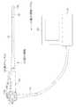
図1において、電子内視鏡システム2は、電子内視鏡10、プロセッサ装置11、および光源装置(図示せず)などから構成される。電子内視鏡10は、体腔内に挿入される挿入部12と、挿入部12の基端部分に連設された操作部13と、プロセッサ装置11や光源装置に接続されるコード14とを備えている。 In FIG. 1, an electronic endoscope system 2 includes an electronic endoscope 10, a
操作部13には、処置具が挿通される鉗子口15が設けられている。この鉗子口15は、点線で示すように、挿入部12内に配設された鉗子チャンネル16に接続される。また、挿入部12の先端に連設された先端部12aには、体腔内撮影用の撮像装置17(図2参照)が内蔵されている。 The
先端部12aの後方には、複数の湾曲駒を連結した湾曲部18が設けられている。この湾曲部18は、操作部13に設けられたアングルノブ13aが操作されて、挿入部12内に挿設されたワイヤが押し引きされることにより、上下左右方向に湾曲動作し、先端部12aが体腔内の所望の方向に向けられるようになっている。 A
プロセッサ装置11には、撮像装置17で取得した撮像信号をデジタル化した画像データに各種画像処理を施す画像処理回路などが、光源装置には、コード14を通して電子内視鏡10に照明光を供給する光源がそれぞれ搭載されている。撮像装置17で撮像した体腔内の画像は、プロセッサ装置11に接続されたモニタ19により観察することが可能となっている。 The
図2において、先端部12aには、観察窓20が設けられている。観察窓20には、体腔内の被観察部位の像光を取り込むための対物光学系(レンズ群)21を保持する鏡筒22が配設されている。鏡筒22は、挿入部12の中心軸12bに対物光学系21の光軸21aが平行となるように取り付けられている。なお、図示はしていないが、先端部12aには、観察窓20の他に、体腔内の被観察部位に光源装置からの照明光を照射するための照明窓や、鉗子口15と鉗子チャンネル16を介して連通した鉗子出口、送気・送水ボタン13b(図1参照)を操作することによって観察窓20の汚れを落とすための洗浄水やエアーが噴射されるノズルなどが設けられている。 In FIG. 2, an
鏡筒22の後端には、鏡筒保持枠22aを介して対物光学系21を経由した被観察部位の像光をCCD23の撮像面23aに導光するプリズム24が接続されている。プリズム24は、その入射面24aが対物光学系21に、出射面24bが後述するカバーガラス30にそれぞれ接続されている。これにより、対物光学系21の光軸21aと撮像面23aとが平行となるように配置される。 Connected to the rear end of the
プリズム24の反射面24cには、薄板状のヒーター25が取り付けられている。ヒーター25には、例えばチップ抵抗やITOからなる透明面発熱フイルムヒーターが用いられ、後述するAMP40やCDS/PGA42(図4参照)などの周辺回路26が実装された基板27側から引き回された配線28が接続されている。 A
配線28は、コード14の先のコネクタ部などに配された後述するヒータードライバ46(図4参照)から引き出されている。ヒーター25は、この配線28を介して電力を供給され、ヒータードライバ46からの制御信号を受けてオン/オフ動作する。 The
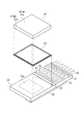
CCD23は、例えばインターライン型のCCDからなり、撮像面23aが表面に設けられたベアチップが用いられる。図3にも示すように、撮像面23a上には、四角枠状のスペーサ29を介して矩形板状のカバーガラス30が取り付けられている。これらCCD23、スペーサ29、およびカバーガラス30は、接着剤で互いに接着されて組み付けられる。 The
CCD23の後端面には、CCD23と略同等の厚さをもつ回路基板31が接着剤により接着されている。回路基板31には、後述するCCDドライバ41(図4参照)などが実装されている。A
CCD23の裏面および回路基板31の裏面には、銀ペーストにより導電板32が取り付けられている。導電板32は、図示しないスルーホールを介してCCD23と回路基板31とを電気的に接続している。この導電板32から、CCD23に電子シャッタの駆動制御信号、例えば、オーバーフロードレイン制御信号が入力される。A
CCD23の回路基板31側の辺縁部には、端子33が集中配置されている。一方、回路基板31には、端子33に対向する辺縁部に、端子34が集中配置されている。端子33と端子34とは、ボンディングワイヤ35により電気的に接続されている。回路基板31の端子33の後端側には、コード14を介してプロセッサ装置11に各種信号を入出力するための信号線36が半田付けされる入出力端子37が設けられている。
基板27の下側の周辺回路26、端子33、34、およびボンディングワイヤ35は、封止剤38により封止されている。封止剤38は、例えば一液硬化性のエポキシ樹脂からなる。 The
撮像装置17を製造する際には、まず、撮像面23a上に、スペーサ29を介してカバーガラス30を取り付ける。カバーガラス30の取り付け後、CCD23の後端面に回路基板31を接着する。次いで、ボンディングワイヤ35により端子33と端子34とを接続し、封止剤38により端子33、34、およびボンディングワイヤ35を封止する。When manufacturing the imaging device 17, first, the
封止剤38の塗布後、CCD23と回路基板31の裏面に導電板32を片側に寄せて懸け渡す。このとき、CCD23および回路基板31に設けたスルーホールを介して、導電板32でCCD23と回路基板31とを電気的に接続する。最後に、鏡筒保持枠22aに接続されたプリズム24の出射面24bに、接着剤によりカバーガラス30を取り付け、ヒーター25に配線28を結線する。After the sealing agent 38 is applied, the
図4において、CCD23には、増幅器(AMP)40およびCCDドライバ41が接続されている。AMP40は、CCD23から出力された撮像信号に所定のゲインで増幅を施し、これを相関二重サンプリング/プログラマブルゲインアンプ(CDS/PGA)42に出力する。In FIG. 4, an amplifier (AMP) 40 and a
CDS/PGA42は、AMP40から出力された撮像信号をCCD23の各セルの蓄積電荷量に正確に対応したR、G、Bの画像データとして出力し、この画像データに増幅を施してA/D変換器(A/D)43に出力する。A/D43は、CDS/PGA42から出力されたアナログの画像データを、デジタルの画像データに変換する。A/D43でデジタル化された画像データは、コード14を介してプロセッサ装置11に送信される。The CDS /
CCDドライバ41には、CPU44によって制御されるタイミングジェネレータ(TG)45が接続されている。CCDドライバ41は、このTG45から入力されるタイミング信号(クロックパルス)により、CCD23の電子シャッタのシャッタ速度などを制御する。A timing generator (TG) 45 controlled by the
CPU44は、コード14を介してプロセッサ装置11と信号の遣り取りを行い、電子内視鏡10の各部の動作を統括的に制御する。CPU44には、前述のCDS/PGA42、TG45の他に、ヒータードライバ46、およびタイマー47が接続されている。The
ヒータードライバ46は、CPU44からの制御信号を受けて、ヒーター25をオン/オフさせる。タイマー47は、ヒーター25がオンされたときに作動し、カバーガラス30の外面30a(プリズム24の出射面24bが接着される面、図3参照)と内面30b(撮像面23aに対向する面、図3参照)とが熱平衡状態になるまでの時間(例えば30秒)経過後に、CPU44にその旨を表す信号を送信する。The
CPU44は、カバーガラス30の外面30aと内面30bとの間に温度差が生じ、カバーガラス30の内面30bに結露が生じるおそれがあるとき、具体的には、電子内視鏡10の電源がオンされたときや、送気・送水ボタン13bが操作されて観察窓20にノズルから洗浄水やエアーが噴射されたときなどに、ヒータードライバ46を介してヒーター25をオンさせ、所定時間経過後にタイマー47から送信される信号を受けて、ヒーター25をオフさせる。The
上記のように構成された電子内視鏡システム2で体腔内を観察する際には、挿入部12を体腔内に挿入し、光源装置をオンして、挿入部12を体腔内に挿入し、体腔内を照明しながら、CCD23による内視鏡画像をモニタ19で観察する。When observing the inside of a body cavity with the electronic endoscope system 2 configured as described above, the
電子内視鏡10の電源がオンされると、CCDドライバ41などが起動され、CCD23による被観察部位の像光の撮像が行われる。対物光学系21から取り込まれた被観察部位の像光は、プリズム24を介して撮像面23aに結像され、これによりCCD23から撮像信号が出力される。When the power source of the electronic endoscope 10 is turned on, the
CCD23から出力された撮像信号は、AMP40で増幅され、CDS/PGA42で相関二重サンプリングおよび増幅が施されて、A/D43でデジタルの画像データに変換される。The imaging signal output from the
A/D43でデジタル化された画像データは、コード14を介してプロセッサ装置11に送信され、プロセッサ装置11で各種画像処理が施された後、内視鏡画像としてモニタ19に表示される。The image data digitized by the A /
電子内視鏡10の電源がオンされたときや、観察窓20に洗浄水やエアーが噴射されたときには、CPU44により、ヒータードライバ46を介してヒーター25がオンされ、これと同時にタイマー47のカウントが開始される。When the power of the electronic endoscope 10 is turned on or when cleaning water or air is sprayed on the
そして、所定時間経過後、タイマー47からCPU44に信号が送信され、この信号を受けたCPU44からヒータードライバ46に制御信号が送信され、ヒーター25がオフされる。これにより、ヒーター25の熱がプリズム24を伝ってカバーガラス30の外面30aに達して温められ、カバーガラス30の外面30aと内面30bとが熱平衡状態となる。Then, after a predetermined time elapses, a signal is transmitted from the
以上詳細に説明したように、電子内視鏡10は、カバーガラス30の内面30bに結露が生じる懸念がある、電子内視鏡10の電源がオンされたときや、観察窓20に洗浄水やエアーが噴射されたときなどに、カバーガラス30の外面30aと内面30bとが熱平衡状態となるまで、プリズム24に取り付けられたヒーター25でカバーガラス30の外面30aを間接的に温めるようにしたので、カバーガラス30の内面30bへの結露を確実に防止することができる。As described above in detail, the electronic endoscope 10 may cause condensation on the inner surface 30b of the
また、ヒーター25を比較的面積の広いプリズム24の反射面24cに取り付けたので、熱の利用効率がよく、急激な温度変化にも対応することができる。さらに、プリズム24はカバーガラス30に直接取り付けられているので、カバーガラス30に均一に熱を伝えることができる。そのうえ、プリズム24の反射面24cの後部は、本来部品が配置されないデッドスペースとなっているので、スペースを有効に活用することができる。In addition, since the
なお、プリズム24の反射面24cにヒーター25を取り付ける代わりに、あるいはこれに加えて、プリズム24の両側面や、鏡筒22の下側部のCCD23近傍にヒーターを設けてもよい。但し、この場合は、鉗子チャンネル16や照明光のライトガイドなど、先端部12に配置される部材との位置の兼ね合いを考慮する必要がある。Instead of attaching the
上記実施形態では、電源がオンされたときや、観察窓20に洗浄水やエアーが噴射されたときにヒーター25をオンさせているが、電子内視鏡10の術者の操作により手動でヒーター25をオン/オフさせるようにしてもよい。In the above embodiment, the
上記実施形態では、CCD23とカバーガラス30との間に空隙を空けるために、スペーサ29を使用しているが、スペーサ29の代わりに透明接着剤を用いてもよく、カバーガラス30に脚を形成してもよい。また、電子内視鏡10側にAMP40やCCDドライバ41などの回路を実装しているが、プロセッサ装置11側に設けてもよい。In the above embodiment, the
また、上記実施形態では、挿入部12の中心軸12bに対物光学系21の光軸21aが平行となるように取り付けた、いわゆる直視型の電子内視鏡10を例に挙げて説明したが、中心軸12bと光軸21aとが垂直となった側視型の電子内視鏡であっても、本発明を適用することが可能である。In the above-described embodiment, the so-called direct-view electronic endoscope 10 that is attached so that the
2 電子内視鏡システム
10 電子内視鏡
11 プロセッサ装置
12 挿入部
12a 先端部
17 撮像装置
21 対物光学系
23 CCD
23a 撮像面
24 プリズム
24a、24b、24c 入射面、出射面、反射面
25 ヒーター
30 カバーガラス
30a、30b 外面、内面
44 CPU
46 ヒータードライバ
47 タイマーDESCRIPTION OF SYMBOLS 2 Electronic endoscope system 10
46
Claims (4)
Translated fromJapanese前記プリズムに取り付けられ、前記プリズムを介して前記出射面が接続された前記カバーガラスの面を温める加熱手段と、
前記加熱手段の動作を制御する制御手段とを備えたことを特徴とする電子内視鏡。An objective optical system for capturing image light of a site to be observed in a body cavity, a solid-state image pickup device that picks up the image light and outputs an image pickup signal, and a space on the image pickup surface of the solid-state image pickup device An image pickup apparatus having a cover glass, and a prism that has an entrance surface and an exit surface connected to the objective optical system and the cover glass and guides image light from the objective optical system to the image pickup surface is built in the tip. In electronic endoscope
A heating means for heating the surface of the cover glass attached to the prism and connected to the exit surface via the prism;
An electronic endoscope comprising control means for controlling the operation of the heating means.
Priority Applications (5)
| Application Number | Priority Date | Filing Date | Title |
|---|---|---|---|
| JP2005282046AJP4758719B2 (en) | 2005-09-28 | 2005-09-28 | Electronic endoscope |
| EP06020250AEP1769725B1 (en) | 2005-09-28 | 2006-09-27 | Electronic endoscope |
| US11/527,392US7455637B2 (en) | 2005-09-28 | 2006-09-27 | Electronic endoscope with heater |
| AT06020250TATE458440T1 (en) | 2005-09-28 | 2006-09-27 | ELECTRONIC ENDOSCOPE |
| DE602006012408TDE602006012408D1 (en) | 2005-09-28 | 2006-09-27 | Electronic endoscope |
Applications Claiming Priority (1)
| Application Number | Priority Date | Filing Date | Title |
|---|---|---|---|
| JP2005282046AJP4758719B2 (en) | 2005-09-28 | 2005-09-28 | Electronic endoscope |
Publications (2)
| Publication Number | Publication Date |
|---|---|
| JP2007089764Atrue JP2007089764A (en) | 2007-04-12 |
| JP4758719B2 JP4758719B2 (en) | 2011-08-31 |
Family
ID=37500023
Family Applications (1)
| Application Number | Title | Priority Date | Filing Date |
|---|---|---|---|
| JP2005282046AExpired - Fee RelatedJP4758719B2 (en) | 2005-09-28 | 2005-09-28 | Electronic endoscope |
Country Status (5)
| Country | Link |
|---|---|
| US (1) | US7455637B2 (en) |
| EP (1) | EP1769725B1 (en) |
| JP (1) | JP4758719B2 (en) |
| AT (1) | ATE458440T1 (en) |
| DE (1) | DE602006012408D1 (en) |
Cited By (4)
| Publication number | Priority date | Publication date | Assignee | Title |
|---|---|---|---|---|
| JP2009058807A (en)* | 2007-08-31 | 2009-03-19 | Olympus Medical Systems Corp | Imaging unit |
| JP2011206079A (en)* | 2010-03-26 | 2011-10-20 | Fujifilm Corp | Imaging unit and endoscope |
| JP2011224348A (en)* | 2010-03-31 | 2011-11-10 | Fujifilm Corp | Endoscopic imaging device and endoscope apparatus |
| JP2013188269A (en)* | 2012-03-12 | 2013-09-26 | Yoshida Dental Mfg Co Ltd | Optical coherence tomography image generating apparatus |
Families Citing this family (15)
| Publication number | Priority date | Publication date | Assignee | Title |
|---|---|---|---|---|
| DE102009013615A1 (en)* | 2009-03-17 | 2010-09-23 | Kaltenbach & Voigt Gmbh | Medical, in particular dental diagnostic device with image acquisition means |
| IL205022A (en)* | 2010-04-12 | 2013-10-31 | Cleanoscope Inc | Lens protector for endoscopic devices |
| US20120075727A1 (en)* | 2010-09-24 | 2012-03-29 | Hoya Corporation | Imaging optical system and imaging apparatus |
| EP4000497A1 (en) | 2011-02-16 | 2022-05-25 | The General Hospital Corporation | Optical coupler for an endoscope |
| ES2951058T3 (en) | 2012-03-09 | 2023-10-17 | 3Shape As | 3D scanner with steam autoclavable tip containing a heated optical element |
| JP6018794B2 (en)* | 2012-05-07 | 2016-11-02 | 富士フイルム株式会社 | Electronic endoscope apparatus, imaging module for endoscope, and operation method of electronic endoscope apparatus |
| EP3150105B1 (en)* | 2013-03-19 | 2018-09-05 | Olympus Corporation | Endoscope apparatus |
| JP6270339B2 (en)* | 2013-05-22 | 2018-01-31 | オリンパス株式会社 | Imaging apparatus, manufacturing method of imaging apparatus, and endoscope system |
| JP5781250B1 (en)* | 2013-10-11 | 2015-09-16 | オリンパス株式会社 | Endoscope system |
| US9459442B2 (en) | 2014-09-23 | 2016-10-04 | Scott Miller | Optical coupler for optical imaging visualization device |
| US10548467B2 (en)* | 2015-06-02 | 2020-02-04 | GI Scientific, LLC | Conductive optical element |
| WO2017015480A1 (en) | 2015-07-21 | 2017-01-26 | GI Scientific, LLC | Endoscope accessory with angularly adjustable exit portal |
| CN105796046A (en)* | 2016-03-25 | 2016-07-27 | 苏州佳世达光电有限公司 | Oral cavity scanner |
| DE102017124593A1 (en)* | 2017-10-20 | 2019-04-25 | Olympus Winter & Ibe Gmbh | Deflection prism assembly for an endoscope with lateral viewing direction, endoscope and method for mounting a deflection prism assembly |
| JP7632042B2 (en)* | 2021-05-11 | 2025-02-19 | コニカミノルタ株式会社 | Intraoral measurement device |
Citations (3)
| Publication number | Priority date | Publication date | Assignee | Title |
|---|---|---|---|---|
| JPH02257926A (en)* | 1989-03-30 | 1990-10-18 | Olympus Optical Co Ltd | Endoscope |
| JPH03118021A (en)* | 1989-09-29 | 1991-05-20 | Olympus Optical Co Ltd | Endoscope device |
| JP2003284686A (en)* | 2002-03-28 | 2003-10-07 | Fuji Photo Optical Co Ltd | Image pickup device for endoscope |
Family Cites Families (10)
| Publication number | Priority date | Publication date | Assignee | Title |
|---|---|---|---|---|
| DE1968844U (en)* | 1967-05-23 | 1967-09-21 | Eltro G M B H & Co Ges Fuer St | ELECTRIC HEATING FOR EXIT WINDOWS OR FRONT LENSES OF OPTICAL DEVICES. |
| US4076018A (en)* | 1974-12-06 | 1978-02-28 | Richard Wolf Gmbh | Endoscopes |
| US5647840A (en)* | 1994-09-14 | 1997-07-15 | Circon Corporation | Endoscope having a distally heated distal lens |
| US5605532A (en)* | 1995-10-20 | 1997-02-25 | Vista Medical Technologies, Inc. | Fog-free endoscope |
| AU1974897A (en) | 1996-02-22 | 1997-09-10 | New Image Industries, Inc. | Apparatus and method for eliminating the fogging of intraoral camera images |
| DE19636354A1 (en)* | 1996-09-02 | 1998-03-05 | Ruedger Dipl Ing Rubbert | Method and device for performing optical recordings |
| US6809303B2 (en)* | 2001-11-13 | 2004-10-26 | Cross Match Technologies, Inc. | Platen heaters for biometric image capturing devices |
| US6866391B2 (en)* | 2001-11-14 | 2005-03-15 | Remote Sights, Ltd. | Thermal condensate reducer for optical devices |
| JP3973939B2 (en)* | 2002-03-22 | 2007-09-12 | フジノン株式会社 | Solid-state imaging device |
| JP2006000282A (en) | 2004-06-16 | 2006-01-05 | Olympus Corp | Fogging preventing device for endoscope and endoscope |
- 2005
- 2005-09-28JPJP2005282046Apatent/JP4758719B2/ennot_activeExpired - Fee Related
- 2006
- 2006-09-27USUS11/527,392patent/US7455637B2/ennot_activeExpired - Fee Related
- 2006-09-27EPEP06020250Apatent/EP1769725B1/ennot_activeNot-in-force
- 2006-09-27ATAT06020250Tpatent/ATE458440T1/ennot_activeIP Right Cessation
- 2006-09-27DEDE602006012408Tpatent/DE602006012408D1/enactiveActive
Patent Citations (3)
| Publication number | Priority date | Publication date | Assignee | Title |
|---|---|---|---|---|
| JPH02257926A (en)* | 1989-03-30 | 1990-10-18 | Olympus Optical Co Ltd | Endoscope |
| JPH03118021A (en)* | 1989-09-29 | 1991-05-20 | Olympus Optical Co Ltd | Endoscope device |
| JP2003284686A (en)* | 2002-03-28 | 2003-10-07 | Fuji Photo Optical Co Ltd | Image pickup device for endoscope |
Cited By (5)
| Publication number | Priority date | Publication date | Assignee | Title |
|---|---|---|---|---|
| US8419616B2 (en) | 2007-08-20 | 2013-04-16 | Olympus Medical Systems Corp. | Image pickup device with a protection member and an optical reflection member |
| JP2009058807A (en)* | 2007-08-31 | 2009-03-19 | Olympus Medical Systems Corp | Imaging unit |
| JP2011206079A (en)* | 2010-03-26 | 2011-10-20 | Fujifilm Corp | Imaging unit and endoscope |
| JP2011224348A (en)* | 2010-03-31 | 2011-11-10 | Fujifilm Corp | Endoscopic imaging device and endoscope apparatus |
| JP2013188269A (en)* | 2012-03-12 | 2013-09-26 | Yoshida Dental Mfg Co Ltd | Optical coherence tomography image generating apparatus |
Also Published As
| Publication number | Publication date |
|---|---|
| EP1769725A1 (en) | 2007-04-04 |
| EP1769725B1 (en) | 2010-02-24 |
| ATE458440T1 (en) | 2010-03-15 |
| US7455637B2 (en) | 2008-11-25 |
| DE602006012408D1 (en) | 2010-04-08 |
| JP4758719B2 (en) | 2011-08-31 |
| US20070073108A1 (en) | 2007-03-29 |
Similar Documents
| Publication | Publication Date | Title |
|---|---|---|
| JP4758719B2 (en) | Electronic endoscope | |
| JP5514755B2 (en) | Endoscope imaging apparatus and endoscope apparatus | |
| JP5384409B2 (en) | Method of operating a CMOS image sensor in an endoscope apparatus | |
| US8462202B2 (en) | Imaging apparatus of electronic endoscope and electronic endoscope | |
| JP5436470B2 (en) | Imaging device and electronic endoscope provided with the same | |
| JP2009240634A (en) | Endoscope apparatus | |
| CN112135557B (en) | Imaging unit and strabismus endoscope | |
| JP2011206336A (en) | Endoscopic system | |
| JP2009261830A (en) | Endoscope system | |
| JP5757906B2 (en) | Imaging apparatus, electronic endoscope apparatus and method for removing condensation thereof | |
| CN105592771A (en) | Imaging module, and endoscope device | |
| US10416438B2 (en) | Imaging device for imaging inside of subject and endoscope device using the same | |
| JP2011206079A (en) | Imaging unit and endoscope | |
| JPH04241830A (en) | Tv camera device for endoscope | |
| JP5289371B2 (en) | Endoscope device and processor device in endoscope system | |
| JP2008237914A (en) | Imaging apparatus | |
| JP4127776B2 (en) | Imaging device | |
| JP5827868B2 (en) | Electronic endoscope and fixed pattern noise removal method | |
| JPH1132985A (en) | Electronic endoscope | |
| JP4597642B2 (en) | Imaging device for electronic endoscope | |
| JP2007260190A (en) | Endoscopic instrument | |
| JP4597643B2 (en) | Electronic endoscope | |
| JP5127596B2 (en) | Processor device for electronic endoscope | |
| JP5398674B2 (en) | Imaging apparatus, electronic endoscope apparatus, and manufacturing method of imaging apparatus | |
| JPH11276433A (en) | Electronic endoscope |
Legal Events
| Date | Code | Title | Description |
|---|---|---|---|
| A621 | Written request for application examination | Free format text:JAPANESE INTERMEDIATE CODE: A621 Effective date:20080515 | |
| A711 | Notification of change in applicant | Free format text:JAPANESE INTERMEDIATE CODE: A711 Effective date:20090828 | |
| A977 | Report on retrieval | Free format text:JAPANESE INTERMEDIATE CODE: A971007 Effective date:20110203 | |
| TRDD | Decision of grant or rejection written | ||
| A01 | Written decision to grant a patent or to grant a registration (utility model) | Free format text:JAPANESE INTERMEDIATE CODE: A01 Effective date:20110511 | |
| A01 | Written decision to grant a patent or to grant a registration (utility model) | Free format text:JAPANESE INTERMEDIATE CODE: A01 | |
| A61 | First payment of annual fees (during grant procedure) | Free format text:JAPANESE INTERMEDIATE CODE: A61 Effective date:20110603 | |
| R150 | Certificate of patent or registration of utility model | Free format text:JAPANESE INTERMEDIATE CODE: R150 Ref document number:4758719 Country of ref document:JP Free format text:JAPANESE INTERMEDIATE CODE: R150 | |
| FPAY | Renewal fee payment (event date is renewal date of database) | Free format text:PAYMENT UNTIL: 20140610 Year of fee payment:3 | |
| R250 | Receipt of annual fees | Free format text:JAPANESE INTERMEDIATE CODE: R250 | |
| R250 | Receipt of annual fees | Free format text:JAPANESE INTERMEDIATE CODE: R250 | |
| R250 | Receipt of annual fees | Free format text:JAPANESE INTERMEDIATE CODE: R250 | |
| R250 | Receipt of annual fees | Free format text:JAPANESE INTERMEDIATE CODE: R250 | |
| R250 | Receipt of annual fees | Free format text:JAPANESE INTERMEDIATE CODE: R250 | |
| R250 | Receipt of annual fees | Free format text:JAPANESE INTERMEDIATE CODE: R250 | |
| LAPS | Cancellation because of no payment of annual fees |