JP2007088723A - Camera for mobile video phone and mobile video phone including the same - Google Patents
Camera for mobile video phone and mobile video phone including the sameDownload PDFInfo
- Publication number
- JP2007088723A JP2007088723AJP2005273830AJP2005273830AJP2007088723AJP 2007088723 AJP2007088723 AJP 2007088723AJP 2005273830 AJP2005273830 AJP 2005273830AJP 2005273830 AJP2005273830 AJP 2005273830AJP 2007088723 AJP2007088723 AJP 2007088723A
- Authority
- JP
- Japan
- Prior art keywords
- frame rate
- camera
- video
- image
- image compression
- Prior art date
- Legal status (The legal status is an assumption and is not a legal conclusion. Google has not performed a legal analysis and makes no representation as to the accuracy of the status listed.)
- Pending
Links
Images


Landscapes
- Studio Devices (AREA)
- Two-Way Televisions, Distribution Of Moving Picture Or The Like (AREA)
- Telephone Function (AREA)
Abstract
Translated fromJapaneseDescription
Translated fromJapanese本発明は、携帯用のテレビ電話機に用いるのに適したカメラに関し、特に、カメラにおけるフレームレートの最適化技術に関する。 The present invention relates to a camera suitable for use in a portable videophone, and more particularly, to a frame rate optimization technique in the camera.
近年、カメラ付き携帯電話の普及に伴い、携帯電話でテレビ電話を行えるようになってきた。一般的なテレビ電話用のカメラは、テレビに表示することを前提に設計されていたため、NTSC(National Television Standards Committee)やPAL(Phase Alternating Line)などのテレビ規格に則ってカメラシステムを設計する必要があり、フレームレートが決定される。また、携帯電話機用のカメラによる画像をテレビ受信機に表示することは前提としてないため、低消費電力化と静止画の撮影とを考慮して設計され、動画時のフレームレートが決定される。また、フレームレートの変更に関連する技術としては、ビデオカメラにおけるフレームレートを、撮像素子駆動回路内に設けられている撮像素子を駆動するための垂直/水平駆動パルス、同期/基準信号および電子シャッタパルスなどを生成している回路の原振を断続的に休止させることで変更する技術がある(特許文献1参照)。 In recent years, with the widespread use of mobile phones with cameras, it has become possible to make videophone calls using mobile phones. Since cameras for general videophones were designed on the assumption that they are displayed on a television, it is necessary to design the camera system in accordance with television standards such as NTSC (National Television Standards Committee) and PAL (Phase Alternating Line). And the frame rate is determined. In addition, since it is not assumed that an image from a camera for a mobile phone is displayed on a television receiver, the frame rate for a moving image is determined by designing in consideration of low power consumption and still image shooting. Further, as a technique related to the change of the frame rate, the frame rate in the video camera is changed to a vertical / horizontal drive pulse, a synchronization / reference signal, and an electronic shutter for driving the image sensor provided in the image sensor drive circuit. There is a technique for changing a circuit that generates a pulse or the like by intermittently stopping the original oscillation (see Patent Document 1).
テレビ電話機では、狭い伝送帯域で伝送できるように画像圧縮技術を利用しているが、圧縮したデータ量により伝送が間に合わず、次のフレームを間引かなければならなくなる場合がある。ところが、NTSCやPALを前提として設計したカメラや、携帯電話を前提としたカメラにおいても、フレームレートはそれぞれの目的を前提とした設計で決められており、決まったフレームレートの画像を間引いて出来るフレームレートでテレビ電話を行っている。 Videophones use image compression technology so that they can be transmitted in a narrow transmission band. However, transmission may not be in time due to the amount of compressed data, and it may be necessary to skip the next frame. However, even with cameras designed for NTSC and PAL, and cameras based on mobile phones, the frame rate is determined based on the design for each purpose, and images with a fixed frame rate can be thinned out. You are making a videophone call at a frame rate.
上記の技術では、テレビ電話機で狭い伝送帯域を効率良く使用することが出来なかった。つまり、携帯電話用のカメラで15フレーム/sでカメラが動作していたとすると、そのままテレビ電話機で全ての画像を送信できるのが好ましいが、動きの激しい場合など情報量が増えると、カメラ出力の1フレーム中で1フレームの画像の伝送が終わらず、次のカメラ出力は単純に間引いており、実際の伝送能力が10フレーム/sあるにもかかわらず、その瞬間に7.5フレーム/sとなってしまい、伝送帯域を効率よく利用できていなかった。その結果としてテレビ電話機の動きが非常に遅くなってしまっていた。 With the above technology, it has been impossible to efficiently use a narrow transmission band in a video phone. In other words, if the camera is operating at 15 frames / s with a camera for a mobile phone, it is preferable that all images can be transmitted as it is with a video phone, but if the amount of information increases, such as when the movement is intense, the camera output The transmission of the image of one frame is not completed in one frame, and the next camera output is simply thinned out. Even though the actual transmission capacity is 10 frames / s, at that moment, 7.5 frames / s. As a result, the transmission band could not be used efficiently. As a result, the movement of the video phone has become very slow.
また、上記特許文献1に記載の技術でも、フレームレートを可変としているが、カメラの原振を止めるためフリッカーなどの対策がとれず、ノイズ等シャッター時間にかかわる原因の改善ができず、圧縮のフレームレート向上は期待できないという問題があった。 Also in the technique described in
本発明は、テレビ電話機において伝送帯域を効率良く利用し、動きが良いテレビ電話を実現する携帯テレビ電話機用カメラを提供することを目的とする。 An object of the present invention is to provide a camera for a portable videophone that realizes a videophone that uses a transmission band efficiently in a videophone and has a good movement.
本発明の一観点によれば、撮像素子からの映像信号を生成する映像信号処理回路から出力された映像信号をテレビ電話機用に圧縮する画像圧縮回路を備えた携帯用テレビ電話機用カメラにおいて、前記画像圧縮回路からの信号により前記撮像素子を駆動するための垂直/水平駆動パルス、同期/基準信号および電子シャッタパルスを含むパルス信号を生成するタイミング発生回路のタイミング・映像光量調整手段を可変し、前記撮像素子から出力される撮像信号のフレームレートと前記画像圧縮回路のフレームレートとが一致する方向に制御することを特徴とした携帯テレビ電話機用カメラが提供される。 According to an aspect of the present invention, in a camera for a portable videophone including an image compression circuit for compressing a video signal output from a video signal processing circuit that generates a video signal from an imaging device, for the videophone, The timing / video light amount adjusting means of the timing generating circuit for generating a pulse signal including a vertical / horizontal driving pulse, a synchronization / reference signal, and an electronic shutter pulse for driving the image sensor by a signal from an image compression circuit, There is provided a camera for a portable videophone, wherein control is performed in a direction in which a frame rate of an image pickup signal output from the image pickup device and a frame rate of the image compression circuit coincide with each other.
前記カメラと前記テレビ電話機圧縮部のフレームレートが合わない時、フレームレートが遅いほうに引っ張られてしまう事がなくなり、常にカメラとテレビ電話のフレームレートが最適な状態を実現する通話が可能となり、ユーザーはより動きのある自然に近い状態で利用することが出来る。 When the frame rate of the camera and the videophone compression unit do not match, it is no longer pulled to the slower frame rate, making a call that always realizes the optimal frame rate of the camera and videophone, Users can use it in a more natural state of motion.
本発明のカメラでは、テレビ電話のフレームレートに合わせて、カメラのフレームレートを変更する。また、カメラのIRIS制御・ホワイトバランス制御・輪郭強調などを制御する。従って、カメラとテレビ電話機のフレームレートが最適な状態で通話可能であり、動きのある自然に近いテレビ電話を利用できる。 In the camera of the present invention, the frame rate of the camera is changed in accordance with the frame rate of the videophone. It also controls camera IRIS control, white balance control, and contour enhancement. Therefore, it is possible to make a call with an optimal frame rate between the camera and the videophone, and a videophone with a natural motion can be used.
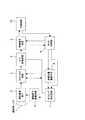
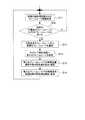
以下に、本発明の実施の形態によるカメラについて、図面を参照して説明する。図1は本発明の第1の実施の形態によるカメラの構成例を示す機能ブロック図である。図2は、本実施の形態によるカメラ制御部における処理の流れを示すフローチャート図である。 A camera according to an embodiment of the present invention will be described below with reference to the drawings. FIG. 1 is a functional block diagram showing a configuration example of a camera according to the first embodiment of the present invention. FIG. 2 is a flowchart showing the flow of processing in the camera control unit according to this embodiment.
図1に示すように、本実施の形態によるビデオカメラは、撮像用レンズ1において被写体からの像を固体撮像素子2に集光し、固体撮像素子2の光電変換素子(フォトダイオード部)において光信号を電気信号に変換した後、タイミング発生回路7において生成された電荷読み出しパルスと、垂直転送パルスおよび水平転送パルスと、を撮像素子駆動回路6により反転昇圧又はドライブ能力を高めた後に固体撮像素子2に入力させることにより、固体撮像素子2の電荷蓄積部に蓄積された信号電荷を固体撮像素子2の転送部により読み出し、読み出された信号電荷を垂直転送/水平転送して出力としている。 As shown in FIG. 1, the video camera according to the present embodiment condenses an image from a subject on a solid-
固体撮像素子2から出力された信号は、CDS/AGC回路3により相関二重サンプリング処理および自動利得調整処理において必要な信号振幅に増幅された後に、A/D変換回路4でディジタル信号に変換される。A/D変換回路4から出力される固体撮像素子2の各画素におけるディジタルデータは、映像信号処理回路5において信号処理され、映像信号が出力される。画像圧縮処理回路10は圧縮画像信号を出力する。 The signal output from the solid-
映像信号処理回路5では、アイリス処理に必要なデータ信号及びホワイトバランス処理に必要なデータ信号を出力している。これらの信号に基づいて、カメラ制御用マイコン9では、アイリス制御、ホワイトバランス制御を行っている。アイリス制御では、入射光量の変化に応じて映像光量調整手段8に指示を与え、タイミング発生回路7において、電子シャッタを変化させたり、CDS/AGC回路3において固体撮像素子2からの信号を増幅する割合を変化させたりしている。ホワイトバランス制御では、映像信号処理回路5にホワイトバランスゲインを与えることにより、様々な色温度下に適応したホワイトバランス調整処理を行う。 The video
カメラ制御マイコン9では、図2に示すように、画像圧縮処理回路10からの情報に関する信号に基づいて判断されるフレームレートと、ステップS1において算出された現在のテレビ電話のフレームレートとを求め、ステップS2において両者を比較し両者が同じ場合には(Y)、フレームレートの変更は行わない。判断されたフレームレートが現在のフレームレートと異なる場合は(N)、ステップS3に進み、可変にできるフレームレートの内から最適なフレームレートを選択し、タイミング発生回路7に対する新たなフレームレートを設定するとともに(ステップS4)、アイリス制御・ホワイトバランス制御を新たなフレームレートに合わせて算出し制御する(ステップS5、S6)。 As shown in FIG. 2, the
以上の処理により、カメラとテレビ電話機の圧縮部のフレームレートが合わない時、フレームレートが遅いほうに引っ張られてしまうことがなくなり、カメラとテレビ電話のフレームレートが最適な状態でテレビ電話による通話ができ、ユーザーは、より動きのある自然に近いテレビ電話機を携帯して利用することが出来る。 With the above processing, when the frame rate of the compression section of the camera and the video phone does not match, the frame rate will not be pulled to the slower side, and the video phone call can be made with the optimal frame rate of the camera and video phone. The user can carry and use a video phone that is closer to nature with more movement.
次に、本発明の第2の実施の形態によるカメラについて、図面を参照して説明する。図3は、本実施の形態によるカメラ制御部における処理の流れを示すフローチャート図である。機能構成は図1に示すものと同様で良い。 Next, a camera according to a second embodiment of the present invention will be described with reference to the drawings. FIG. 3 is a flowchart showing a flow of processing in the camera control unit according to the present embodiment. The functional configuration may be the same as that shown in FIG.
図3に示すように、ステップS11においては、図1の画像圧縮処理回路10からの情報に関する信号のうちテレビ電話機のフレームレート信号を用いる点を特徴とする。ステップS12においてそのフレームレートが現在のフレームレートと同じ場合は(Y)フレームレートの変更は行わない。判断されたフレームレートが現在のフレームレートと違う場合は(N)、ステップS13に進み、可変できるフレームレートのうち最適なフレームレートを選択し、ステップS14においてタイミング発生回路7に新たなフレームレートを設定する。合わせてアイリス制御・ホワイトバランス制御を次のフレームレートに合わせて算出し制御する(ステップS15、16)。 As shown in FIG. 3, step S11 is characterized in that a frame rate signal of a videophone is used among signals related to information from the image
以上に説明したように、本実施の形態によるカメラにおいては、画像圧縮処理回路からの情報に関する信号としてテレビ電話機のフレームレート信号を用いることにより、カメラとテレビ電話のフレームレートが最適な状態でテレビ電話による通話ができ、ユーザーは、より動きのある自然に近いテレビ電話機を携帯して利用することが出来るという利点を有する。 As described above, in the camera according to the present embodiment, the frame rate signal of the video phone is used as a signal related to information from the image compression processing circuit, so that the frame rate of the camera and the video phone is optimized. A telephone call can be made, and the user has the advantage of being able to carry and use a video phone that is closer to nature with more movement.
次に、本発明の第3の実施の形態によるカメラについて図面を参照しつつ説明を行う。
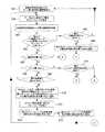
図4A、図4Bは、本実施の形態によるカメラ制御部の処理の流れを示すフローチャート図である。図4A,Bに示すように、本実施の形態においては、画像圧縮処理回路10からの信号として、データ量と動き検出量とを用いる(ステップS21)点を特徴とする。ステップS22において、データ量から現在のテレビ電話機のフレームレートを算出し、現在のフレームレートと同じであれば(Y)変更は行わない。算出されたテレビ電話機のフレームレートが現在のフレームレートと異なる場合には(N)ステップS24に進み、データ量と動き検出量とから異なる要因を推測し、最適なフレームレートを選択し、タイミング発生回路7に新たなフレームレートを設定する。Next, a camera according to a third embodiment of the present invention will be described with reference to the drawings.
4A and 4B are flowcharts showing the flow of processing of the camera control unit according to the present embodiment. As shown in FIGS. 4A and 4B, the present embodiment is characterized in that a data amount and a motion detection amount are used as signals from the image compression processing circuit 10 (step S21). In step S22, the current frame rate of the videophone is calculated from the amount of data, and if it is the same as the current frame rate (Y), no change is made. If the calculated frame rate of the videophone is different from the current frame rate (N), the process proceeds to step S24, a different factor is estimated from the data amount and the motion detection amount, the optimum frame rate is selected, and the timing is generated. A new frame rate is set in the
要因はデータ量と動き検出量とから推測し、データ量が多く動き検出量も多い場合は、画面全体の動きが大きいためデータ量が増えていると推測できる。データ量が少なめで、動き検出量が多い場合には画面の一部が動いていると推測できるため、算出されたテレビ電話機のフレームレートに合わせた最適なフレームレートに設定する。データ量が多く、動き検出量が少ない時には、電子シャッターの制御状態から暗い場合にはノイズ多い画面であり、明るい時には細かい画面であると推測できる。ノイズの多い画面と推測した場合には算出されたテレビ電話のフレームレートとし、電子シャッターをより遅くする制御を行い、細かい画像と推測された場合にはカメラの映像処理回路へ輪郭強調を弱める設定を行い、算出されたTV電話のフレームレートよりも少し早いフレームレートに設定する。 The cause is estimated from the amount of data and the amount of motion detection. When the amount of data is large and the amount of motion detection is large, it can be estimated that the amount of data is increased because the motion of the entire screen is large. If the amount of data is small and the amount of motion detection is large, it can be estimated that a part of the screen is moving. Therefore, the optimal frame rate is set in accordance with the calculated frame rate of the videophone. When the amount of data is large and the amount of motion detection is small, it can be presumed that the screen is noisy when it is dark from the control state of the electronic shutter and is a fine screen when it is bright. When the screen is estimated to be noisy, the calculated video phone frame rate is used, and the electronic shutter is controlled to be slower, and if it is estimated to be a fine image, the camera image processing circuit is set to weaken contour enhancement. To set a frame rate slightly faster than the calculated video phone frame rate.
より具体的には、ステップS24において動き検出量が多いか否かを判断し、多くない場合には(N)ステップS25に進みデータ量が多いか否かを判断する。多くないと判断された場合には(N)ステップS21に戻る。多いと判断された場合には(Y)、ステップS26に進み、電子シャッター制御状態が暗い画面か否かを判断する。暗い画面ではないと判断された場合には(N)ステップS27に進み、細かい画面と推測し、現在のテレビ電話機のフレームレートより少し早いフレームレートを可変できるフレームレートから選択する。次いで、ステップS28において、タイミング発生回路へ新たなフレームレートを設定し、ステップS29において新たなフレームレートでの映像コウリョウ調整手段の設定値を算出・設定する。ステップS30において、新たなフレームレートでの映像信号処理回路の設定値を算出・設定し、輪郭強調を弱めに設定する。 More specifically, it is determined in step S24 whether or not the amount of motion detection is large. If not, (N) the process proceeds to step S25 to determine whether or not the amount of data is large. If it is determined that there are not many (N), the process returns to step S21. If it is determined that there are many (Y), the process proceeds to step S26, and it is determined whether or not the electronic shutter control state is a dark screen. If it is determined that the screen is not dark (N), the process proceeds to step S27, where a fine screen is estimated, and a frame rate that is slightly faster than the frame rate of the current videophone is selected. Next, in step S28, a new frame rate is set in the timing generation circuit, and in step S29, the setting value of the video image adjusting means at the new frame rate is calculated and set. In step S30, the setting value of the video signal processing circuit at the new frame rate is calculated and set, and the edge enhancement is set to be weak.
ステップS26において電子シャッター制御状態が暗い画面と判断された場合には(Y)、ステップS31に進み、ノイズが多い画面と推測し、現在のテレビ電話機のフレームレートとほぼ同じフレームレートを、可変できるフレームレートから選択する。ステップS32において、タイミング発生回路へ新たなフレームレートを設定し、ステップS33において新たなフレームレートで露光時間をより多くするよう映像光量調整手段の設定値を算出・設定し、ステップS34において新たなフレームレートでの映像信号処理回路の設定値を算出・設定。輪郭強調を弱めに設定する。ステップS24において動き変化量が多いと判断された場合には(Y)、ステップS35においてデータ量が多いか否かを判断し、多くないと判断された場合には(N)、ステップS36において画面の一部が動いていると推測。現在のTV電話のフレームレートとほぼ同等のフレームレートを可変出来るフレームレートから選択する。ステップS35においてデータ量が多いと判断された場合には(Y)、ステップS37に進み画面全体が動いていると推測。現在のTV電話のフレームレートとほぼ同等のフレームレートを可変出来るフレームレートから選択する。いずれの場合でも、その後はステップS38においてタイミング発生回路へ新たなフレームレートを設定し、ステップS39において新たなフレームレートでの映像光量調整手段の設定値を算出・設定し、ステップS40において新たなフレームレートでの映像信号処理回路の設定値を算出・設定する。いずれの場合も、ステップS21に戻る。 If it is determined in step S26 that the electronic shutter control state is a dark screen (Y), the process proceeds to step S31, where it is assumed that the screen has a lot of noise, and the frame rate substantially the same as the current videophone frame rate can be varied. Select from frame rate. In step S32, a new frame rate is set in the timing generation circuit. In step S33, the set value of the image light amount adjusting means is calculated and set so as to increase the exposure time at the new frame rate. In step S34, a new frame rate is set. Calculate and set the set value of the video signal processing circuit at the rate. Set the edge enhancement weaker. If it is determined in step S24 that the movement change amount is large (Y), it is determined in step S35 whether or not the data amount is large. If it is determined that the amount of data is not large (N), the screen is displayed in step S36. I guess some of them are moving. Select a frame rate that can be changed to a frame rate that is almost the same as the current video phone frame rate. If it is determined in step S35 that the amount of data is large (Y), the process proceeds to step S37 and it is estimated that the entire screen is moving. Select a frame rate that can be changed to a frame rate that is almost the same as the current video phone frame rate. In any case, after that, in step S38, a new frame rate is set in the timing generation circuit, in step S39, the setting value of the image light amount adjusting means at the new frame rate is calculated and set, and in step S40, a new frame rate is set. Calculate and set the set value of the video signal processing circuit at the rate. In either case, the process returns to step S21.
次に、本発明の第4の実施の形態について図面を参照しつつ説明を行う。図5は本実施の形態によるカメラ制御部の処理の流れを示すフローチャート図である。本実施の形態においては、カメラ制御マイコン9では画像圧縮処理回路10からの信号から判断されるフレームレートと映像信号処理回路5からの情報とから、次のフレームレートが変わるかを推測し、次のフレームレートが変わると推測された時には予めカメラのフレームレートを変更する。フレームレートが現在のフレームレートと違う場合には、画像圧縮回路10と映像信号処理回路5とからの信号を元に次のフレームレートが変わるか否かを推測し、可変できるフレームレートのうち最適なフレームレートを選択し、タイミング発生回路7に新たなフレームレートを設定する。合わせてアイリス制御・ホワイトバランス制御を次のフレームレートに合わせて算出し制御する。 Next, a fourth embodiment of the present invention will be described with reference to the drawings. FIG. 5 is a flowchart showing the flow of processing of the camera control unit according to this embodiment. In the present embodiment, the
より具体的には、ステップS51において画像圧縮処理回路からの情報取得・現在のテレビ電話機のフレームレート算出し、ステップ52において映像信号処理回路からの情報を取得する。ステップS53において、現在のテレビ電話機のフレームレートと推測したカメラのフレームレートは同じで次のフレームレートは変わらないと推測できるか異かを判定し、推測可能な場合には(Y)ステップS51に戻る。推測できない場合にはステップS54に進み、可変出来るフレームレートから最適なフレームレートを選択し、ステップS55においてタイミング発生回路へ新たなフレームレートを設定し、ステップS56において新たなフレームレートでの映像光量調整手段の設定値を算出・設定し、ステップS57において新たなフレームレートでの映像信号処理回路の設定値を算出・設定し、ステップS51に戻る。 More specifically, in step S51, information is acquired from the image compression processing circuit, and the current videophone frame rate is calculated. In step 52, information from the video signal processing circuit is acquired. In step S53, it is determined whether the current frame rate of the videophone is the same as the estimated frame rate of the camera and it can be estimated that the next frame rate will not change. If it can be estimated (Y), the process proceeds to step S51. Return. If it cannot be estimated, the process proceeds to step S54, an optimum frame rate is selected from the variable frame rates, a new frame rate is set in the timing generation circuit in step S55, and the video light amount adjustment at the new frame rate is performed in step S56. The setting value of the means is calculated and set, and the setting value of the video signal processing circuit at the new frame rate is calculated and set in step S57, and the process returns to step S51.
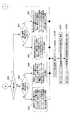
次に、本発明の第5の実施の形態によるカメラについて図面を参照しつつ説明を行う。図6A、図6B、図6Cは本実施の形態によるカメラ制御部の処理の流れを示すフローチャート図である。本実施の形態においては、画像圧縮処理回路10からの信号にデータ量と動き検出量を用い、映像信号処理回路5からの信号に露出積算値を用い、データ量から現在のテレビ電話機のフレームレートを算出し、現在のフレームレートと同じで、露出積算値がほとんど変化の無い場合には動きが無い画像と推測し変更は行わない。露出積算値の変化が大きい場合には次のフレームは動きが大きい画像と推測し、その次のフレームのフレームレートをあらかじめ変化させる。算出されたテレビ電話のフレームレートが現在のフレームレートを違う場合にはデータ量・動き検出量・露出積算値から要因を推測し、最適なフレームレートを選択し、タイミング発生回路7に新たなフレームレートを設定する。 Next, a camera according to a fifth embodiment of the present invention will be described with reference to the drawings. 6A, 6B, and 6C are flowcharts showing the flow of processing of the camera control unit according to the present embodiment. In the present embodiment, the data amount and the motion detection amount are used for the signal from the image
要因はデータ量・動き検出量・露出積算値から推測し、データ量が多く動き検出量も多く、露出積算値の変化量も多い場合、画面全体の動きが大きく、次のフレームもデータ量が増えると推測でき、露出積算値の変化量が少ない場合には次のフレームのデータ量は変化が少ないと推測でき、データ量が少なめで、動き検出量が多く、露出積算値の変化量も多い場合、画面の一部が動いていて次のフレームのデータ量が増加すると推測でき、露出積算値の変化量が少ない場合には次のフレームのデータ量も変化が少ないと推測でき、算出されたテレビ電話機のフレームレートに合わせた最適なフレームレートに設定する。 The cause is estimated from the amount of data, the amount of motion detection, and the integrated exposure value. If the amount of change in the exposure integrated value is small, it can be estimated that the amount of data in the next frame is small, the amount of data is small, the amount of motion detection is large, and the amount of change in the exposure integrated value is also large. In this case, it can be estimated that a part of the screen is moving and the data amount of the next frame increases, and if the amount of change in the exposure integrated value is small, it can be estimated that the data amount of the next frame is also small. Set the optimal frame rate to match the video phone frame rate.
データ量が多く、動き検出量が少なく、露出積算値の変化量が多い時には、細かい画面かノイズが多い画面で次のフレームのデータ量が多くなると推測でき、露出積算値の変化量が少ない場合には次のフレームのデータ量も少ないと推測でき、電子シャッターの制御状態から暗い場合にはノイズ多い画面、明るい時には細かい画面かが推測でき、ノイズが多く露出積算値の変化量が多い場合には次のフレームのデータ量の変化が大きく、露出積算値の変化量が少ない場合には次のフレームのデータ量の変化も少ないと推測でき、次のフレームレートは算出されたテレビ電話のフレームレートに合わせた最適なフレームレートに設定する。 When the amount of data is large, the amount of motion detection is small, and the amount of change in the exposure integrated value is large, it can be estimated that the data amount of the next frame will increase on a fine screen or a screen with much noise, and the amount of change in the exposure integrated value is small The amount of data in the next frame can be estimated to be small, and when the electronic shutter control state is dark, it can be estimated that the screen is noisy when it is dark, or the screen is fine when it is bright, and when there is a lot of noise and the amount of change in the exposure integrated value is large If the change in the data amount of the next frame is large and the change in the exposure integrated value is small, it can be estimated that the change in the data amount of the next frame is small, and the next frame rate is the calculated frame rate of the videophone. Set the optimal frame rate according to the
合わせて電子シャッターを最適にし、カメラの映像処理回路の輪郭強調を最適にする設定する行いう。細かい画像と推測され露出変化量が多い場合には次のフレームのデータ量が多くなると判断でき、露出変化量が少ない場合には次のフレームのデータ量の変化が少ないと判断でき、次のフレームは算出されたテレビ電話機のフレームレートに合わせた最適なフレームレートを設定する。合わせてカメラの映像処理回路へ輪郭強調を最適にする設定を行う。より具体的には、図6A〜Cに示す流れとなるが、ステップS61からステップS102までの各処理は図面に沿って行われるためこれを援用する。 At the same time, the electronic shutter is optimized, and the outline enhancement of the video processing circuit of the camera is optimized. When it is estimated that the image is fine and the amount of change in exposure is large, it can be determined that the amount of data in the next frame is large. Sets an optimal frame rate in accordance with the calculated frame rate of the videophone. At the same time, the camera image processing circuit is set to optimize the edge enhancement. More specifically, the flow is as shown in FIGS. 6A to 6C, and each process from step S61 to step S102 is performed in accordance with the drawing, which is incorporated herein.
以上に説明したように、本発明の各実施の形態によるカメラでは、上記のようにテレビ電話機のフレームレートに合わせ、カメラのフレームレートを変更し、合わせてカメラのIRIS制御・ホワイトバランス制御・輪郭強調などを制御するため、常にカメラとテレビ電話機のフレームレートが最適な状態を実現することができる。従って、ユーザは、より動きのある自然に近いテレビ電話機を携帯電話機においても利用することができるという利点がある。 As described above, in the camera according to each embodiment of the present invention, as described above, the camera frame rate is changed in accordance with the video phone frame rate, and the camera IRIS control, white balance control, contour Since the emphasis and the like are controlled, it is possible to always realize an optimal frame rate between the camera and the video phone. Therefore, there is an advantage that the user can use a more natural moving video phone with a mobile phone.
本発明は、テレビ電話機に利用可能である。 The present invention is applicable to a video phone.
1 撮像用レンズ
2 固体撮像素子
3 CDS/AGC回路
4 A/D変換回路
5 映像信号処理回路
6 撮像素子駆動回路
7 タイミング発生回路
8 映像光量調整手段
9 カメラ制御部
10 画像圧縮処理回路DESCRIPTION OF
Claims (7)
Translated fromJapanese前記画像圧縮回路からの信号により前記撮像素子を駆動するための垂直/水平駆動パルス、同期/基準信号および電子シャッタパルスを含むパルス信号を生成するタイミング発生回路のタイミング・映像光量調整手段を可変にし、前記撮像素子から出力される撮像信号のフレームレートと前記画像圧縮回路のフレームレートとが一致する方向に制御することを特徴とした携帯テレビ電話機用カメラ。In a camera for a portable video phone provided with an image compression circuit for compressing a video signal output from a video signal processing circuit that generates a video signal from an image sensor for a video phone,
The timing / video light quantity adjusting means of the timing generating circuit for generating a pulse signal including a vertical / horizontal driving pulse, a synchronization / reference signal, and an electronic shutter pulse for driving the image pickup device by a signal from the image compression circuit is made variable. A camera for a mobile videophone, wherein the control is performed in a direction in which a frame rate of an image pickup signal output from the image pickup device and a frame rate of the image compression circuit match.
前記画像圧縮回路からの信号と映像信号処理から出力された信号を元に、撮像素子を駆動するための垂直/水平駆動パルス、同期/基準信号および電子シャッタパルスを生成しているタイミング発生回路のタイミング・映像光量調整手段を可変し、前記撮像素子から出力される撮像信号のフレームレートを前記画像圧縮回路のフレームレートに一致させる方向に制御することを特徴とする携帯テレビ電話機用カメラ。In a camera for a portable video phone provided with an image compression circuit for compressing a video signal output from a video signal processing circuit that generates a video signal from an image sensor for a video phone,
A timing generation circuit that generates vertical / horizontal drive pulses, synchronization / reference signals, and electronic shutter pulses for driving the image sensor based on the signal from the image compression circuit and the signal output from the video signal processing; A camera for a portable videophone, wherein the timing / video light amount adjusting means is varied to control the frame rate of an image pickup signal output from the image pickup device in a direction matching the frame rate of the image compression circuit.
前記画像圧縮回路からの信号により、前記撮像素子から出力される撮像信号のフレームレートと前記画像圧縮回路のフレームレートとが一致する方向に制御することを特徴とした携帯テレビ電話機用カメラ。In a camera for a portable video phone provided with an image compression circuit for compressing a video signal output from a video signal processing circuit that generates a video signal from an image sensor for a video phone,
A camera for a mobile videophone, wherein a signal from the image compression circuit is controlled so that a frame rate of an image pickup signal output from the image pickup device and a frame rate of the image compression circuit coincide with each other.
A portable video phone comprising the camera according to any one of claims 1 to 6.
Priority Applications (1)
| Application Number | Priority Date | Filing Date | Title |
|---|---|---|---|
| JP2005273830AJP2007088723A (en) | 2005-09-21 | 2005-09-21 | Camera for mobile video phone and mobile video phone including the same |
Applications Claiming Priority (1)
| Application Number | Priority Date | Filing Date | Title |
|---|---|---|---|
| JP2005273830AJP2007088723A (en) | 2005-09-21 | 2005-09-21 | Camera for mobile video phone and mobile video phone including the same |
Publications (1)
| Publication Number | Publication Date |
|---|---|
| JP2007088723Atrue JP2007088723A (en) | 2007-04-05 |
Family
ID=37975277
Family Applications (1)
| Application Number | Title | Priority Date | Filing Date |
|---|---|---|---|
| JP2005273830APendingJP2007088723A (en) | 2005-09-21 | 2005-09-21 | Camera for mobile video phone and mobile video phone including the same |
Country Status (1)
| Country | Link |
|---|---|
| JP (1) | JP2007088723A (en) |
Cited By (11)
| Publication number | Priority date | Publication date | Assignee | Title |
|---|---|---|---|---|
| JP2010020079A (en)* | 2008-07-10 | 2010-01-28 | Canon Inc | Image processing apparatus, image processing method and program |
| JP2011507343A (en)* | 2007-12-05 | 2011-03-03 | オンライブ インコーポレイテッド | System to accelerate web page delivery |
| JP2011507339A (en)* | 2007-12-05 | 2011-03-03 | オンライブ インコーポレイテッド | A system that combines multiple views of real-time streaming interactive video |
| JP2011508478A (en)* | 2007-12-05 | 2011-03-10 | オンライブ インコーポレイテッド | How to multicast a view of real-time streaming interactive video |
| JP2011509545A (en)* | 2007-12-05 | 2011-03-24 | オンライブ インコーポレイテッド | System for collaborative meetings using streaming interactive video |
| US9108107B2 (en) | 2002-12-10 | 2015-08-18 | Sony Computer Entertainment America Llc | Hosting and broadcasting virtual events using streaming interactive video |
| US9118968B2 (en) | 2002-12-10 | 2015-08-25 | Sony Computer Entertainment America Llc | Method for user session transitioning among streaming interactive video servers |
| US9573059B2 (en) | 2002-12-10 | 2017-02-21 | Sony Interactive Entertainment America Llc | Streaming interactive video integrated with recorded video segments |
| US9700790B2 (en) | 2002-12-10 | 2017-07-11 | Sony Interactive Entertainment America Llc | System and method for compressing streaming interactive video |
| US9707481B2 (en) | 2002-12-10 | 2017-07-18 | Sony Interactive Entertainment America Llc | System for streaming databases serving real-time applications used through streaming interactive video |
| US10286315B2 (en) | 2002-12-10 | 2019-05-14 | Sony Interactive Entertainment America Llc | System for combining recorded application state with application streaming interactive video output |
- 2005
- 2005-09-21JPJP2005273830Apatent/JP2007088723A/enactivePending
Cited By (13)
| Publication number | Priority date | Publication date | Assignee | Title |
|---|---|---|---|---|
| US9623326B2 (en) | 2002-12-10 | 2017-04-18 | Sony Interactive Entertainment America Llc | System for collaborative conferencing using streaming interactive video |
| US9032465B2 (en) | 2002-12-10 | 2015-05-12 | Ol2, Inc. | Method for multicasting views of real-time streaming interactive video |
| US9108107B2 (en) | 2002-12-10 | 2015-08-18 | Sony Computer Entertainment America Llc | Hosting and broadcasting virtual events using streaming interactive video |
| US9118968B2 (en) | 2002-12-10 | 2015-08-25 | Sony Computer Entertainment America Llc | Method for user session transitioning among streaming interactive video servers |
| US9573059B2 (en) | 2002-12-10 | 2017-02-21 | Sony Interactive Entertainment America Llc | Streaming interactive video integrated with recorded video segments |
| US9700790B2 (en) | 2002-12-10 | 2017-07-11 | Sony Interactive Entertainment America Llc | System and method for compressing streaming interactive video |
| US9707481B2 (en) | 2002-12-10 | 2017-07-18 | Sony Interactive Entertainment America Llc | System for streaming databases serving real-time applications used through streaming interactive video |
| US10286315B2 (en) | 2002-12-10 | 2019-05-14 | Sony Interactive Entertainment America Llc | System for combining recorded application state with application streaming interactive video output |
| JP2011507343A (en)* | 2007-12-05 | 2011-03-03 | オンライブ インコーポレイテッド | System to accelerate web page delivery |
| JP2011507339A (en)* | 2007-12-05 | 2011-03-03 | オンライブ インコーポレイテッド | A system that combines multiple views of real-time streaming interactive video |
| JP2011508478A (en)* | 2007-12-05 | 2011-03-10 | オンライブ インコーポレイテッド | How to multicast a view of real-time streaming interactive video |
| JP2011509545A (en)* | 2007-12-05 | 2011-03-24 | オンライブ インコーポレイテッド | System for collaborative meetings using streaming interactive video |
| JP2010020079A (en)* | 2008-07-10 | 2010-01-28 | Canon Inc | Image processing apparatus, image processing method and program |
Similar Documents
| Publication | Publication Date | Title |
|---|---|---|
| JP5715436B2 (en) | Imaging apparatus and control method thereof | |
| JP5802520B2 (en) | Imaging device | |
| KR100868054B1 (en) | Imaging device, image blurring reduction method and recording medium thereof | |
| US8681236B2 (en) | Apparatus and method for reducing shutter lag of a digital camera | |
| US7580058B2 (en) | Image capturing apparatus and image capturing method | |
| CN103369239A (en) | Image processing apparatus and method for camera | |
| JP2010136224A (en) | Imaging apparatus and imaging method | |
| JP2007088723A (en) | Camera for mobile video phone and mobile video phone including the same | |
| US8654204B2 (en) | Digtal photographing apparatus and method of controlling the same | |
| JP4761048B2 (en) | Imaging apparatus and program thereof | |
| JP4919637B2 (en) | Imaging apparatus and imaging method | |
| JP2006174412A (en) | Imaging apparatus | |
| JP2010136301A (en) | Imaging apparatus and solid-state imaging element therefor | |
| JP4869801B2 (en) | Imaging device | |
| JP2015056758A (en) | Imaging apparatus, its control method and control program | |
| US8411181B2 (en) | Image pick-up apparatus for controlling generation of an electronic shutter pulse signal based on one of a detected brightness of an imaging object and an obtained current exposure value, and method and non-transitory computer readable recording medium therefor | |
| JP4807218B2 (en) | Imaging apparatus and program | |
| RU2430482C1 (en) | Image forming device and method of controlling said device | |
| JP5299747B2 (en) | Portable terminal with camera, photographing method, and photographing program | |
| JP2001069400A (en) | Imaging device | |
| JP2008071150A (en) | Image processing apparatus, image processing program, and photographing apparatus | |
| JP2008236718A (en) | IMAGING DEVICE AND IMAGING DEVICE CONTROL METHOD | |
| JP2006180350A (en) | Imaging apparatus | |
| JP2006148456A (en) | Electronic camera | |
| JP2007243769A (en) | Camera |