JP2007084010A - Oil-containing wastewater treatment ship - Google Patents
Oil-containing wastewater treatment shipDownload PDFInfo
- Publication number
- JP2007084010A JP2007084010AJP2005278520AJP2005278520AJP2007084010AJP 2007084010 AJP2007084010 AJP 2007084010AJP 2005278520 AJP2005278520 AJP 2005278520AJP 2005278520 AJP2005278520 AJP 2005278520AJP 2007084010 AJP2007084010 AJP 2007084010A
- Authority
- JP
- Japan
- Prior art keywords
- oil
- containing wastewater
- storage tank
- purified
- waste
- Prior art date
- Legal status (The legal status is an assumption and is not a legal conclusion. Google has not performed a legal analysis and makes no representation as to the accuracy of the status listed.)
- Granted
Links
- 238000004065wastewater treatmentMethods0.000titleclaimsabstractdescription33
- 239000002351wastewaterSubstances0.000claimsabstractdescription145
- XLYOFNOQVPJJNP-UHFFFAOYSA-NwaterSubstancesOXLYOFNOQVPJJNP-UHFFFAOYSA-N0.000claimsabstractdescription80
- 239000002699waste materialSubstances0.000claimsabstractdescription76
- 238000011084recoveryMethods0.000claimsabstractdescription29
- 238000000746purificationMethods0.000claimsabstractdescription13
- 238000000926separation methodMethods0.000claimsdescription19
- 238000001914filtrationMethods0.000claimsdescription17
- 238000007689inspectionMethods0.000claimsdescription11
- 239000003921oilSubstances0.000description242
- 238000012545processingMethods0.000description29
- 239000004576sandSubstances0.000description9
- OKTJSMMVPCPJKN-UHFFFAOYSA-NCarbonChemical compound[C]OKTJSMMVPCPJKN-UHFFFAOYSA-N0.000description6
- 238000000034methodMethods0.000description6
- 239000010802sludgeSubstances0.000description5
- 239000000428dustSubstances0.000description4
- 206010033307OverweightDiseases0.000description2
- 238000010586diagramMethods0.000description2
- 230000005484gravityEffects0.000description2
- 238000009434installationMethods0.000description2
- 108010066114cabin-2Proteins0.000description1
- 238000004140cleaningMethods0.000description1
- 239000000295fuel oilSubstances0.000description1
- 239000002440industrial wasteSubstances0.000description1
- 238000012423maintenanceMethods0.000description1
- 239000013535sea waterSubstances0.000description1
- 238000012360testing methodMethods0.000description1
- 238000012546transferMethods0.000description1
- 238000005406washingMethods0.000description1
Images


Landscapes
- Removal Of Floating Material (AREA)
- Water Treatment By Sorption (AREA)
Abstract
Translated fromJapaneseDescription
Translated fromJapanese本発明は、船舶や海上から含油廃水を回収し浄化処理する含油廃水処理船に関する。 The present invention relates to an oil-containing wastewater treatment ship that collects and purifies oil-containing wastewater from a ship or the sea.
船舶の船底には、エンジン等からの油を含有したビルジ水、水バラスト(錘)、タンク洗浄水等が含油廃水として溜まる。従来、この含油廃水は回収後、陸上の廃油処理施設まで移送され、そこで油水分離処理が行われている。
しかしながら、このように陸上に設置された処理施設まで含油廃水を移送するのは、作業に掛かるコストと時間とを多大に要するため効率的ではなかった。On the bottom of the ship, bilge water containing oil from an engine or the like, water ballast (weight), tank washing water, and the like collect as oil-containing wastewater. Conventionally, this oil-containing wastewater is collected and transferred to a land-based waste oil treatment facility where oil-water separation treatment is performed.
However, it is not efficient to transfer the oil-containing wastewater to the treatment facility installed on land in this way because it requires a lot of work cost and time.
このような問題に対し、特許文献1(特許第3428898号公報)には、船舶内に設置され、その船舶の船底に溜まる含油廃水(油含有ビルジ水)の油分と水分とを分離して回収する船舶ビルジ用浮遊油回収装置が開示されている。この浮遊油回収装置によれば、船舶内のビルジタンク等に溜まった含油廃水の水面に浮遊する浮遊油を、ビルジポンプによって吸引して油水分離槽に収容し、ここで油分と水分とに分離し、油分は廃油タンクに収容し、水分は船舶内のビルジタンク等に帰還するようになされる。
特許文献1に開示された浮遊油回収装置によれば、含油廃水を生じる船舶内にその装置を設置することにより、含油廃水に浮遊する油分を取り除くことができ、ビルジ廃油処理のメンテナンスが容易となる。
しかしながら、そのような浮遊油回収装置は一般には未だ普及しておらず、殆どの船舶においては、前記したように含油廃水は地上の処理施設まで移送回収後、その処理施設において廃油水分離処理が行われている。According to the floating oil recovery device disclosed in Patent Document 1, by installing the device in a ship that generates oil-containing wastewater, oil floating in the oil-containing wastewater can be removed, and maintenance of bilge waste oil treatment is easy. Become.
However, such floating oil recovery devices are not yet widespread in general, and in most ships, as described above, oil-containing wastewater is transported and recovered to a treatment facility on the ground, and then the waste oil and water separation treatment is performed at the treatment facility. Has been done.
また、船舶の座礁、沈没等の海難事故により船舶から海上に流出した多量の燃料油、積荷油等に対しては、特許文献1に示される浮遊油回収装置程度の処理能力では対処できず、回収船による油水回収後、地上における処理施設において廃油水分離処理が行われている。
即ち、現況にあっては、殆どの船舶での含油廃水や、海難事故等により海上に流出した油に対しては、油回収船等による回収後、その油水分離処理等は地上の廃油処理施設で行われており、その結果、作業に掛かるコストと時間とを多大に要し、効率的な含油廃水処理環境が提供されているとは云えない。Also, a large amount of fuel oil, cargo oil, etc. that have flowed out of the ship due to marine accidents such as ship landing, sinking, etc. cannot be handled with the processing capacity of the floating oil recovery device shown in Patent Document 1, After oil and water recovery by the recovery vessel, waste oil and water separation processing is performed at a treatment facility on the ground.
In other words, in the present situation, oil-containing wastewater in most ships and oil that has flowed out to the sea due to maritime accidents, etc. are recovered by oil recovery vessels, etc., and then the oil-water separation processing is performed on the ground waste oil treatment facility. As a result, the cost and time required for work are greatly required, and it cannot be said that an efficient oil-containing wastewater treatment environment is provided.
本発明は、前記したような事情の下になされたものであり、他の船舶内で生じた含油廃水や海上に流出した含油廃水を現場にて回収し、直ちに油水分離処理を行うことにより、作業に掛かるコストと時間を低減し、効率的な含油廃水処理を行うことのできる含油廃水処理船を提供することを目的とする。 The present invention has been made under the circumstances as described above, and by collecting oil-containing wastewater generated in other ships and oil-containing wastewater flowing out to the sea on-site, immediately performing oil-water separation treatment, An object of the present invention is to provide an oil-containing wastewater treatment ship capable of reducing the cost and time required for work and performing an efficient oil-containing wastewater treatment.
前記した課題を解決するために、本発明に係る含油廃水処理船は、船舶で生じた含油廃水または海上に流出した含油廃水を回収し浄化処理する含油廃水処理船であって、曳航または自走により航行可能に形成された船体と、前記船体の上部及び内部に設けられた廃油処理機構とを備え、前記廃油処理機構は、前記船舶または海上から前記含油廃水を回収する回収手段と、前記回収手段により回収された含油廃水を収容する原水収容タンクと、前記原水収容タンクに収容された含油廃水のうち、自然分離浮上した上層部の油分を捕集する油分捕集手段と、前記原水収容タンクに収容された含油廃水のうち、下層部の含油廃水を取り出して油分を取り除き、浄化済廃水を精製する浄化手段と、前記浄化手段により精製された浄化済廃水を収容する浄化済廃水収容タンクと、前記油分捕集手段により捕集された油分と前記浄化手段により取り除かれた油分とを廃油として収容する廃油収容タンクとを有することに特徴を有する。 In order to solve the above-described problems, an oil-containing wastewater treatment ship according to the present invention is an oil-containing wastewater treatment ship that recovers and purifies oil-containing wastewater generated in a ship or oil-containing wastewater that has flowed out to sea, and is towed or self-propelled. And a waste oil treatment mechanism provided in an upper portion and inside of the hull, the waste oil treatment mechanism comprising: a recovery means for recovering the oil-containing wastewater from the ship or the sea; and the recovery A raw water storage tank for storing the oil-containing wastewater collected by the means, an oil content collection means for collecting the oil content of the upper layer that naturally separated and floated from the oil-containing wastewater stored in the raw water storage tank, and the raw water storage tank Of the oil-containing wastewater stored in the tank, the oil-containing wastewater in the lower layer is taken out to remove the oil, and the purified wastewater purified by the purification means is stored. Kasumi wastewater containing tank, characterized in that it has a waste oil containing tank for containing the oil that has been removed as a waste oil by said oil collecting means and said purifying means and oil trapped by.
このように、曳航または自走により航行可能な船体の上部及び内部に廃油処理機構を備えているため、他の船舶で生じた含油廃水や海難事故等により海上に流出した含油水を回収し、その場で油水分離処理を行い、処理廃水を浄化し、浄化済廃水として海上に還元することができる。
即ち、従来は、一旦、回収船等により含油廃水を回収し陸上の廃油処理施設で処理を行っていた作業を回収現場で行うことができるため、掛かるコストや作業時間が低減され、効率的な含油廃水処理を行うことができる。
また、海上で作業を行うため、既存する陸上の廃油処理施設に比べ、廃水を運搬するための作業車両の作業エリア等の土地確保が不要であり、小さい設置面積で廃油処理機構を形成することができる。これにより、廃油処理機構の設置に要するコストの面でも低減することができる。In this way, because it has a waste oil treatment mechanism in the upper part and inside of the hull that can be navigated by towing or self-propelled, it collects oil-containing wastewater that has flowed out to the sea due to oil-containing wastewater generated by other ships or maritime accidents, etc. Oil-water separation treatment can be performed on the spot to purify the treated wastewater and return it to the sea as purified wastewater.
In other words, in the past, once the oil-containing wastewater was recovered by a recovery ship or the like and processed at the waste oil treatment facility on land, it can be performed at the recovery site. Oil-containing wastewater treatment can be performed.
In addition, because the work is performed at sea, it is not necessary to secure land such as the work area of the work vehicle for transporting waste water compared to existing land waste oil treatment facilities, and a waste oil treatment mechanism should be formed with a small installation area. Can do. Thereby, the cost required for installing the waste oil treatment mechanism can also be reduced.
また、前記浄化手段は、前記含油廃水から前記浄化済廃水を精製するまでの流水路を形成する流水路形成手段と、前記原水収容タンクの下層部から前記流水路を介して取り出された含油廃水を、油分と含油水分とに分離する油水分離手段と、前記油水分離手段により分離された含油水分から残存する油分を低減し浄化済廃水を精製するフィルタリング手段とを有し、前記油水分離手段により分離された油分は前記流水路を介して前記廃油収容タンクに収容され、前記フィルタリング手段により精製された浄化済廃水は前記流水路を介して前記浄化済廃水収容タンクに収容されることが望ましい。
このように自然分離による油分と水分の分離方法に加え、機械的に含油廃水を浄化する手段を備えることにより、廃水中の油分を殆ど取り除くことができ、浄化した浄化済廃水を、その場で海に還元することができる。The purification means includes a flow channel forming means for forming a flow channel from the oil-containing waste water to the purification of the purified waste water, and an oil-containing waste water taken out from the lower layer portion of the raw water storage tank via the flow channel. Oil and water separation means for separating oil into oil-containing moisture, and filtering means for reducing oil remaining from the oil-containing moisture separated by the oil-water separation means and purifying purified wastewater, by the oil-water separation means The separated oil is preferably stored in the waste oil storage tank via the flow channel, and the purified waste water purified by the filtering means is stored in the purified waste water storage tank via the flow channel.
In this way, in addition to the method for separating oil and water by natural separation, by providing a means for mechanically purifying oil-containing wastewater, it is possible to remove almost all oil in the wastewater, and the purified purified wastewater can be removed on the spot. It can be reduced to the sea.
また、前記浄化廃水収容タンクに収容された浄化済廃水の油分含有率を測定する油分検査手段を備え、前記油分検査手段により測定された油分含有率が所定値内となる浄化済廃水は海上に放流されることが望ましい。
このように構成すれば、浄化した廃水が海に還元できるものかどうか、その場で判別することができる。In addition, an oil content inspection means for measuring the oil content rate of the purified waste water stored in the purified waste water storage tank is provided, and the purified waste water whose oil content rate measured by the oil content inspection means falls within a predetermined value is on the sea. It is desirable to be discharged.
If comprised in this way, it can be discriminate | determined on the spot whether the purified waste water can be returned to the sea.
また、前記油分検査手段により測定された油分含有率が所定値より高い浄化済廃水は、前記フィルタリング手段によりさらに油分が低減されて前記浄化廃水収容タンクに収容され、前記油分検査手段により再測定された油分含有率が所定値内であれば海上に放流されることが望ましい。
このように構成すれば、廃水を海に還元できる状態にするまで浄化処理することができる。Purified wastewater whose oil content measured by the oil content inspection means is higher than a predetermined value is further reduced in oil content by the filtering means and stored in the purified wastewater storage tank, and remeasured by the oil content inspection means. If the oil content is within a predetermined value, it is desirable to be discharged to the sea.
If comprised in this way, it can purify | clean-up until it becomes a state which can reduce wastewater to the sea.
また、前記原水収容タンクは、前記船体の略中央部に配置され、前記廃油収容タンクは、前記原水収容タンクの略中央部に配置されることが望ましい。
このように回収された含油廃水が先ず収容され、高重量となる原水収容タンクを船体の中央部に配置し、さらにスラッジやゴミを含むことで高重量となる廃油を収容する廃油収容タンクを原水収容タンクの中央部に配置することにより、廃油処理の経過に拘らず、船体の重心バランスを保つことができる。Further, it is preferable that the raw water storage tank is disposed at a substantially central portion of the hull, and the waste oil storage tank is disposed at a substantially central portion of the raw water storage tank.
The oil-containing wastewater collected in this way is stored first, and a high-weight raw water storage tank is placed in the center of the hull, and a waste-oil storage tank that stores high-weight waste oil by containing sludge and garbage is also used as raw water. By arranging it at the center of the storage tank, the balance of the center of gravity of the hull can be maintained regardless of the progress of the waste oil treatment.
本発明によれば、他の船舶内で生じた含油廃水や海上に流出した含油廃水を現場にて回収し、直ちに油水分離処理を行うことにより、作業に掛かるコストと時間を低減し、効率的な含油廃水処理を行うことのできる含油廃水処理船を得ることができる。 According to the present invention, oil-containing wastewater generated in other ships or oil-containing wastewater that has flowed out to the sea is collected on-site and immediately subjected to oil-water separation treatment, thereby reducing the cost and time required for the work and improving efficiency. It is possible to obtain an oil-containing wastewater treatment ship capable of performing an oil-containing wastewater treatment.
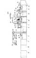
以下、本発明の実施の形態を図面に基づき説明する。図1は本発明に係る含油廃水処理船の全体を示す側面図、図2は図1の含油廃水処理船が具備する廃油処理機構の全体構成を示す透視斜視図である。 Hereinafter, embodiments of the present invention will be described with reference to the drawings. FIG. 1 is a side view showing the entire oil-containing wastewater treatment ship according to the present invention, and FIG. 2 is a perspective view showing the overall structure of a waste oil treatment mechanism provided in the oil-containing wastewater treatment ship shown in FIG.
図1に示す含油廃水処理船100は、他の自走式船による曳航により、又は、自走することにより航行可能に形成された平底の船体1を具備し、この船体1には指令室となるキャビン2が設けられている。そして、含油廃水処理船100は他の船舶や海上から含油廃水を回収し、油水分離処理を行う廃油処理機構10を備え、この廃油処理機構10は、船体1の上部及び内部の容積の殆どを占めている。即ち、この含油廃水処理船100は廃油処理を専門に行う船であり、多量の含油廃水であっても、それを回収し油水分離処理等ができるようになされている。 An oil-containing
廃油処理機構10は、図2に示すように複数の処理タンクを備える。先ず、廃油処理機構10の中央、即ち船体1の略中央に相当する位置に、他の船舶や海上から回収された含油廃水(原水)を収容するための原水収容タンク11が設けられる。そしてさらに、この原水収容タンク11の中央部には、回収された含油廃水から取り除かれた油分からなる廃油や、スラッジ、ゴミ等を収容する廃油収容タンク12が設けられる。
即ち、回収された含油廃水が先ず収容され、高重量となる原水収容タンク11を船体の中央部に配置し、さらにスラッジやゴミを含むことで高重量となる廃油を収容する廃油収容タンク12を原水収容タンク11の中央部に配置することにより、廃油処理の経過に拘らず、船体の重心バランスを保つことができるように構成されている。The waste
That is, the recovered oil-containing wastewater is first stored, and the raw
また、原水収容タンク11よりも船首側には、後述のフィルタリング処理等により油分が低減された処理廃水(含油水分)を収容する処理タンク14、15と、油分が略取り除かれた状態の浄化済廃水を収容する浄化済廃水収容タンク16とが隣接されている。また、原水収容タンク11よりも船尾側には、予備タンク17、18、19が順に隣接されている。尚、予備タンク17、18、19は、多目的に利用することができるが、例えば、夫々の予備タンクを処理タンク14、15及び浄化済処理タンク16のいずれかと同様の用途に用い、浄化処理能力を向上させることもできる。 Further, on the bow side of the raw
また、廃油処理機構10は、他の船舶200等から含油廃水を回収するためのパイプや図示しないポンプ等からなる回収ライン(回収手段)20を備え、この回収ライン20は他の船舶200と、原水収容タンク11との間を接続する。また、回収ライン20には、流量計21が設けられ、原水収容タンク11内に回収される廃水量が監視できるようになされている。 Further, the waste
また、この廃油処理機構10は、原水収容タンク11に収容される含油原水の水面付近(上層部)に浮遊する油分を捕集するスキマー装置(油分捕集手段)36を備える。このスキマー装置36と廃油収容タンク12との間には、パイプ37が設けられる。これにより、原水収容タンク11内で上層部に自然分離浮上した油分がスキマー装置36により捕集され、廃油収容タンク12へ送出されるようになされている。 The waste
また、廃油処理機構10は、原水収容タンク11に収容される含油廃水のうち、下層部から含油廃水を取り出し、その油分を機械的手段により取り除いて浄化済廃水を精製する浄化手段を有している。この浄化手段としては、先ず油水分離器(油水分離手段)22を備え、この油水分離器22と原水収容タンク11との間にパイプ23が設けられている。尚、パイプ23の原水収容タンク11側の端部は、タンク底部付近に設置されている。
即ち、原水収容タンク11内の含油廃水のうち、下層部の含油廃水がパイプ23により油水分離器22に送出され、油分と含油水分(処理廃水)とに分離されるようになされている。また、油分分離器22と廃油収容タンク12との間には、パイプ24が設けられ、油分分離器22で分離された油分が、パイプ24を介して廃油収容タンク12に回収されるようになされている。In addition, the waste
That is, of the oil-containing wastewater in the raw
また、この廃油処理機構10は、前記洗浄手段として、複数のフィルタからなるフィルタリング手段を備える。このフィルタリング手段としては先ず、油分分離器22で概ね油分と分離された処理廃水(含油水分)からさらに油分を取り除くためのフィルタボックス25を備える。油分分離器22とフィルタボックス25との間には、油分分離器22からフィルタボックス25に処理廃水を送出するためのパイプ26が設けられている。また、フィルタボックス25と処理タンク13との間にはパイプ27が設けられ、フィルタボックス25で油分がさらに取り除かれた処理廃水(含油水分)がパイプ27を介して処理タンク14に収容されるようになっている。 In addition, the waste
尚、処理タンク14に収容される処理廃水の水面付近(上層部)にはスキマー装置38が設けられる。このスキマー装置38と廃油収容タンク12との間には、パイプ39が設けられる。これにより、処理タンク14内で上層部に自然分離浮上した油分がスキマー装置38により捕集され、廃油収容タンク12へ送出されるように構成されている。 Note that a
また、廃油処理機構10は、前記フィルタリング手段としてサンドフィルタ29を備える。そして、このサンドフィルタ29と処理タンク14との間には、処理タンク14からサンドフィルタ29に処理廃水を送出するためのパイプ30が設けられている。即ち、処理タンク14内の処理廃水がパイプ30を介してサンドフィルタ29に送出され、そこでさらに処理廃水中の油分が低減されるようになされている。また、サンドフィルタ29から処理タンク15に処理廃水を送出するためのパイプ31が設けられ、サンドフィルタ29により油分が低減された後の処理廃水が処理タンク15に収容されるようになされている。 In addition, the waste
また、この廃油処理機構10は、前記フィルタリング手段として取換えが容易なカートリッジフィルタ32をさらに備える。そして、処理タンク15とカートリッジフィルタ32との間には、処理タンク15からカートリッジフィルタ32に含油廃水を送出するためのパイプ33が設けられている。
処理タンク15内の処理廃水はパイプ33を介してカートリッジフィルタ32に送出され、そこで殆どの残留油分が取り除かれ、浄化済廃水が精製されるようになされている。カートリッジフィルタ32で浄化された浄化済廃水は、パイプ34を介して浄化済廃水収容タンク16に収容されるようになされている。
また、浄化済廃水収容タンク16には、海上に向けタンク内の浄化済廃水を海上に放流できるように排出ライン35が設けられている。The waste
The treatment wastewater in the
The purified waste
尚、浄化済廃水収容タンク16には、収容する浄化済廃水が含有する油分の濃度(油分含有率)を測定する油検出器(油分検査手段)50が設けられる。即ち、浄化した廃水が海に還元できるものかどうか、その場で判断できるようになされている。そして、この油検出器50において浄化済廃水収容タンク16内の浄化済廃水の含有油分が所定値内となる場合には、排出ライン35から海上に浄化済廃水が放流される。
一方、油分濃度が所定値(基準値)より高くなった場合には、さらにフィルタリング手段としての粒状活性炭カートリッジフィルタ51により油分を除去し、さらに浄化された海水を浄化済廃水収容タンク16に再収容後、前記所定値内の油分濃度になされた後に海上に放流される。The purified waste
On the other hand, when the oil concentration is higher than a predetermined value (reference value), the oil content is further removed by the granular activated
また、廃油収容タンク12に回収された廃油のうち、タンク底部に溜まったスラッジやゴミは回収ライン40を介して陸上のタンクローリー201等に送出され、その他の廃油は回収ライン41を介して陸上の他のタンクローリー202等に送出されるように構成されている。尚、回収ライン40、41は夫々、図示しないポンプ等を備え、そのポンプにより廃油が送出される。 Of the waste oil collected in the waste
尚、前記したパイプ23、24、26、27、30、31、33、34と、それらパイプを通じて処理廃水を送出させるための図示しないポンプ等により流水路形成手段が構成されている。 The above-described
続いて、このように構成された廃油処理機構10を備えた含油廃水処理船100が、例えば他の船舶200から含油廃水を回収し処理する場合の工程について図3、図4に基づいて説明する。
図3は、廃油処理機構10における廃油処理工程を説明するため、その構造をより模式的に示した図である。図4は、廃油処理機構10における処理工程の流れを示すフロー図である。Subsequently, a process in a case where the oil-containing
FIG. 3 is a diagram schematically showing the structure of the waste oil treatment process in the waste
先ず、含油廃水処理船100は、回収ライン20を介して船舶200から含油廃水を回収し、原水収容タンク11に収容する(図4のステップS1)。
ここで、原水収容タンク11に収容された含油廃水(原水)のうち、上層部に自然分離浮上した油分はスキマー装置36により捕集され、廃油収容タンク12に回収される(図4のステップS2)。First, the oil-containing
Here, of the oil-containing waste water (raw water) stored in the raw
また、原水収容タンク11に収容された含油廃水のうち、下層部の含油廃水は、パイプ23を介して油水分離器22に送出され、油分と含油水分(処理廃水)とに分離される(図4のステップS3)。
そして、油水分離器22により分離された油分は、廃油収容タンク12に収容され、一方、前記油分が分離された処理廃水(含油水分)は、フィルタボックス25により廃水内に残存する油分が低減される(図4のステップS4)。
フィルタボックス25により油分が低減された処理廃水は、先ず処理タンク14に収容される。そして、処理タンク14に収容された処理廃水に対し、残存する油分をさらに低減するため、サンドフィルタ29によるフィルタリング処理がなされる(図4のステップS5)。Of the oil-containing wastewater stored in the raw
The oil separated by the oil /
The treated wastewater whose oil content has been reduced by the
サンドフィルタ29によりさらに油分が低減された処理廃水は、処理タンク15に収容された後、さらにカートリッジフィルタ32によるフィルタリング処理がなされ、そこで殆どの油分が除去される(図4のステップS6)。
そして、カートリッジフィルタ32によりフィルタリング処理された廃水は、浄化済廃水として浄化済廃水収容タンク16に収容され、そこで油検出器50により水質検査が行われる(図4のステップS7)。The treated wastewater whose oil content has been further reduced by the
The wastewater filtered by the
この検査の結果、浄化済廃水の油分濃度(油分含有率)が所定値(基準値)内であれば(図4のステップS8)、その浄化済廃水は海上に放流される(図4のステップS9)。
一方、油分濃度が所定値より高ければ、再度、所定値内の油分濃度となるまで、粒状活性炭カートリッジフィルタ51によりフィルタリング処理がなされ、所定値内の油分濃度となった場合に、その浄化済廃水は海上に放流される(図4のステップS6)。
尚、廃油収容タンク12内に回収された廃油のうち、タンク底部に溜まったスラッジやゴミは、回収ライン40を介して陸上のタンクローリー201等に送出され、その他の廃油は回収ライン41を介して陸上の他のタンクローリー202等に送出される。As a result of this inspection, if the oil concentration (oil content) of the purified wastewater is within a predetermined value (reference value) (step S8 in FIG. 4), the purified wastewater is discharged to the sea (step in FIG. 4). S9).
On the other hand, if the oil concentration is higher than the predetermined value, filtering processing is performed by the granular activated
Of the waste oil collected in the waste
以上のように本実施の形態によれば、航行可能な船体の上部及び内部に、多量の含油廃水を処理可能な廃油処理機構を備えているため、他の船舶で生じた含油廃水や海難事故等により海上に流出した含油水を回収し、その場で油水分離処理を行い、処理廃水を浄化し、浄化済廃水として海上に還元することができる。
即ち、従来は、一旦、回収船等により含油廃水を回収し陸上の廃油処理施設で処理を行っていた作業を回収現場で行うことができるため、掛かるコストや作業時間が低減され、効率的な含油廃水処理を行うことができる。
また、海上で移動作業を行うため、既存する陸上の廃油処理施設に比べ、廃水を運搬するための作業車両の作業エリア等の土地確保が不要であり、小さい設置面積で廃油処理機構を形成することができる。これにより、廃油処理機構の設置に要するコストの面でも低減することができる。As described above, according to the present embodiment, since the waste oil treatment mechanism capable of treating a large amount of oil-containing wastewater is provided in the upper and inside of the navigable hull, oil-containing wastewater and maritime accidents that have occurred in other ships It is possible to collect oil-containing water that has flowed out to the sea by means of the above, perform oil-water separation treatment on the spot, purify the treated wastewater, and return it to the sea as purified wastewater.
In other words, in the past, once the oil-containing wastewater was recovered by a recovery ship or the like and processed at the waste oil treatment facility on land, it can be performed at the recovery site. Oil-containing wastewater treatment can be performed.
In addition, since the work is carried out at sea, it is not necessary to secure land such as the work area of the work vehicle for transporting waste water compared to existing land waste oil treatment facilities, and a waste oil treatment mechanism is formed with a small installation area. be able to. Thereby, the cost required for installing the waste oil treatment mechanism can also be reduced.
尚、前記実施の形態においては、他の船舶や海上から含油廃水を回収する回収手段としてパイプや図示しないポンプ等からなる回収ライン20により、船舶等から直接、含油廃水を回収する例を図示等により示したが、他の回収手段として、図示しない自走式回収船を用いて含油廃水を回収し、含油廃水処理船100に持ち込むようにしてもよい。 In the above-described embodiment, an example in which oil-containing wastewater is directly recovered from a ship or the like by a
本発明は、他の船舶で生じた含油廃水や、海難事故等により海上に流出した含油廃水を回収し、浄化処理する含油廃水処理船に関し、産業廃棄物処理業界において好適に用いることができる。 The present invention relates to an oil-containing wastewater treatment ship that collects and purifies oil-containing wastewater that has flowed out of the sea due to a marine accident or the like, and can be suitably used in the industrial waste treatment industry.
1 船体(指令室)
10 廃油処理機構
11 原水収容タンク
12 廃油収容タンク
14、15 処理タンク
16 浄化済廃水収容タンク
17、18、19 予備タンク
20 回収ライン(回収手段)
21 流量計
22 油水分離器(油水分離手段)
23、24 パイプ(流路形成手段)
25 フィルタボックス(フィルタリング手段)
26、27 パイプ(流路形成手段)
29 サンドフィルタ(フィルタリング手段)
30、31 パイプ(流路形成手段)
32 カートリッジフィルタ(フィルタリング手段)
33、34 パイプ(流路形成手段)
35 排出ライン
36 スキマー装置(油分捕集手段)
37 パイプ(油分捕集手段)
38 スキマー装置
50 油検出器(油分検査手段)
51 粒状活性炭カートリッジフィルタ(特殊油分捕集手段)
100 含油廃水処理船1 Hull (command room)
DESCRIPTION OF
21
23, 24 Pipe (flow path forming means)
25 Filter box (filtering means)
26, 27 Pipe (flow path forming means)
29 Sand filter (filtering means)
30, 31 Pipe (flow path forming means)
32 Cartridge filter (filtering means)
33, 34 Pipe (flow path forming means)
35
37 Pipe (Oil collecting means)
38
51 Granular activated carbon cartridge filter (special oil collecting means)
100 Oil-impregnated wastewater treatment ship
Claims (5)
Translated fromJapanese曳航または自走により航行可能に形成された船体と、前記船体の上部及び内部に設けられた廃油処理機構とを備え、
前記廃油処理機構は、
前記船舶または海上から前記含油廃水を回収する回収手段と、前記回収手段により回収された含油廃水を収容する原水収容タンクと、前記原水収容タンクに収容された含油廃水のうち、自然分離浮上した上層部の油分を捕集する油分捕集手段と、前記原水収容タンクに収容された含油廃水のうち、下層部の含油廃水を取り出して油分を取り除き、浄化済廃水を精製する浄化手段と、前記浄化手段により精製された浄化済廃水を収容する浄化済廃水収容タンクと、前記油分捕集手段により捕集された油分と前記浄化手段により取り除かれた油分とを廃油として収容する廃油収容タンクとを有することを特徴とする含油廃水処理船。An oil-containing wastewater treatment ship that collects and purifies oil-containing wastewater generated on a ship or oil-containing wastewater that flows out to the sea,
A hull formed to be able to navigate by towing or self-propelled, and a waste oil treatment mechanism provided in an upper part and inside of the hull,
The waste oil treatment mechanism is:
The recovery means for recovering the oil-containing wastewater from the ship or the sea, the raw water storage tank for storing the oil-containing wastewater recovered by the recovery means, and the upper layer naturally separated and floating among the oil-containing wastewater stored in the raw water storage tank Oil collecting means for collecting the oil content of the part, purification means for removing the oil content from the oil-containing waste water stored in the raw water storage tank, removing the oil content, and purifying the purified waste water, and the purification A purified wastewater storage tank for storing purified wastewater purified by the means, and a waste oil storage tank for storing the oil collected by the oil collection means and the oil removed by the purification means as waste oil An oil-containing wastewater treatment ship characterized by that.
前記含油廃水から前記浄化済廃水を精製するまでの流水路を形成する流水路形成手段と、前記原水収容タンクの下層部から前記流水路を介して取り出された含油廃水を、油分と含油水分とに分離する油水分離手段と、前記油水分離手段により分離された含油水分から残存する油分を低減し浄化済廃水を精製するフィルタリング手段とを有し、
前記油水分離手段により分離された油分は前記流水路を介して前記廃油収容タンクに収容され、前記フィルタリング手段により精製された浄化済廃水は前記流水路を介して前記浄化済廃水収容タンクに収容されることを特徴とする請求項1に記載された含油廃水処理船。The purification means includes
The flow channel forming means for forming a flow channel from the oil-containing waste water to the purification of the purified waste water, and the oil-containing waste water taken out from the lower part of the raw water storage tank through the flow channel, the oil and the oil-containing moisture And an oil / water separation means for separating the oil and water, and a filtering means for reducing the oil content remaining from the oil-containing water separated by the oil / water separation means and purifying the purified wastewater,
Oil separated by the oil / water separation means is accommodated in the waste oil storage tank via the flow channel, and purified waste water purified by the filtering means is accommodated in the purified waste water storage tank via the flow channel. The oil-containing wastewater treatment ship according to claim 1.
前記油分検査手段により測定された油分含有率が所定値内となる浄化済廃水は海上に放流されることを特徴とする請求項1または請求項2に記載された含油廃水処理船。Oil content inspection means for measuring the oil content of the purified wastewater stored in the purified wastewater storage tank,
3. The oil-containing wastewater treatment ship according to claim 1, wherein the purified wastewater whose oil content measured by the oil content inspection means falls within a predetermined value is discharged to the sea.
前記廃油収容タンクは、前記原水収容タンクの略中央部に配置されることを特徴とする請求項1乃至請求項4のいずれかに記載された含油廃水処理船。The raw water storage tank is disposed in a substantially central portion of the hull,
The oil-containing wastewater treatment ship according to any one of claims 1 to 4, wherein the waste oil storage tank is disposed at a substantially central portion of the raw water storage tank.
Priority Applications (1)
| Application Number | Priority Date | Filing Date | Title |
|---|---|---|---|
| JP2005278520AJP4243603B2 (en) | 2005-09-26 | 2005-09-26 | Oil-containing wastewater treatment ship |
Applications Claiming Priority (1)
| Application Number | Priority Date | Filing Date | Title |
|---|---|---|---|
| JP2005278520AJP4243603B2 (en) | 2005-09-26 | 2005-09-26 | Oil-containing wastewater treatment ship |
Publications (2)
| Publication Number | Publication Date |
|---|---|
| JP2007084010Atrue JP2007084010A (en) | 2007-04-05 |
| JP4243603B2 JP4243603B2 (en) | 2009-03-25 |
Family
ID=37971437
Family Applications (1)
| Application Number | Title | Priority Date | Filing Date |
|---|---|---|---|
| JP2005278520AActiveJP4243603B2 (en) | 2005-09-26 | 2005-09-26 | Oil-containing wastewater treatment ship |
Country Status (1)
| Country | Link |
|---|---|
| JP (1) | JP4243603B2 (en) |
Cited By (5)
| Publication number | Priority date | Publication date | Assignee | Title |
|---|---|---|---|---|
| US20110011584A1 (en)* | 2009-07-17 | 2011-01-20 | Adam Bernays | Produced water disposal |
| JP2011126408A (en)* | 2009-12-17 | 2011-06-30 | Kanto Kosan Kk | Wastewater treatment ship |
| JP2015030455A (en)* | 2013-08-05 | 2015-02-16 | ホ イ、ジョン | Oil recovery device |
| WO2015156118A1 (en)* | 2014-04-11 | 2015-10-15 | 住友電気工業株式会社 | Oil-water separation treatment system and oil-water separation treatment method |
| CN113121030A (en)* | 2019-12-30 | 2021-07-16 | 山东东顺环保科技有限公司 | Oily wastewater treatment device |
- 2005
- 2005-09-26JPJP2005278520Apatent/JP4243603B2/enactiveActive
Cited By (7)
| Publication number | Priority date | Publication date | Assignee | Title |
|---|---|---|---|---|
| US20110011584A1 (en)* | 2009-07-17 | 2011-01-20 | Adam Bernays | Produced water disposal |
| US8540023B2 (en)* | 2009-07-17 | 2013-09-24 | Single Buoy Moorings, Inc. | Produced water disposal |
| JP2011126408A (en)* | 2009-12-17 | 2011-06-30 | Kanto Kosan Kk | Wastewater treatment ship |
| US8298415B2 (en) | 2009-12-17 | 2012-10-30 | Kanto Kosan Co., Ltd. | Wastewater treatment ship |
| JP2015030455A (en)* | 2013-08-05 | 2015-02-16 | ホ イ、ジョン | Oil recovery device |
| WO2015156118A1 (en)* | 2014-04-11 | 2015-10-15 | 住友電気工業株式会社 | Oil-water separation treatment system and oil-water separation treatment method |
| CN113121030A (en)* | 2019-12-30 | 2021-07-16 | 山东东顺环保科技有限公司 | Oily wastewater treatment device |
Also Published As
| Publication number | Publication date |
|---|---|
| JP4243603B2 (en) | 2009-03-25 |
Similar Documents
| Publication | Publication Date | Title |
|---|---|---|
| JP5357731B2 (en) | Wastewater treatment ship | |
| KR101096538B1 (en) | Marine water automatic separation and recovery system | |
| US8864985B2 (en) | Oil decanting system | |
| KR101036621B1 (en) | Drain processing unit | |
| WO2008110762A1 (en) | Process for treatment of ballast water aboard ships | |
| US11299407B2 (en) | Ballast water, bilge water, slop water, or oily water treatment systems | |
| KR101722590B1 (en) | Contaminated drain water recovery system for vessel | |
| Amran et al. | Oil–water separation techniques for bilge water treatment | |
| WO2022085582A1 (en) | Floating pollutant collection device and floating pollutant collection system | |
| JP4243603B2 (en) | Oil-containing wastewater treatment ship | |
| US20210071379A1 (en) | Transportable modular system for emergency treatment of water polluted by liquid hydrocarbon spillage | |
| EP0739858A2 (en) | Liquid separator and polishing filter thereof | |
| KR100542338B1 (en) | Oil and water separator with scale filter module | |
| KR20180012002A (en) | Maintenance Floating Dock Provided With Dewatering System of Pontoon Deck | |
| US8540023B2 (en) | Produced water disposal | |
| KR101346237B1 (en) | Wastewater treatment system of a vessel | |
| JP2007237939A (en) | Wastewater treatment vessel | |
| JP2009045549A (en) | Daily life drainage treatment ship | |
| KR101867022B1 (en) | Zero discharge system for ship | |
| KR20100070682A (en) | Ship for preventing oil pollution of sea | |
| CN1231390C (en) | Oil-water separatior for separating micro-seston of bilge | |
| JP3131169B2 (en) | Barge-mounted oil-water separator | |
| KR100469950B1 (en) | Bilge water treatment device | |
| KR20240015772A (en) | Marine Polluted Water Treatment System And Treatment Method Using Hydrocyclone And Compact Flotation Unit | |
| KR200479288Y1 (en) | Drain water recycling system of drillship and recyling method thereof |
Legal Events
| Date | Code | Title | Description |
|---|---|---|---|
| A977 | Report on retrieval | Free format text:JAPANESE INTERMEDIATE CODE: A971007 Effective date:20080311 | |
| A131 | Notification of reasons for refusal | Free format text:JAPANESE INTERMEDIATE CODE: A131 Effective date:20080319 | |
| A521 | Request for written amendment filed | Free format text:JAPANESE INTERMEDIATE CODE: A523 Effective date:20080411 | |
| A521 | Request for written amendment filed | Free format text:JAPANESE INTERMEDIATE CODE: A523 Effective date:20080519 | |
| A521 | Request for written amendment filed | Free format text:JAPANESE INTERMEDIATE CODE: A821 Effective date:20080519 | |
| TRDD | Decision of grant or rejection written | ||
| A01 | Written decision to grant a patent or to grant a registration (utility model) | Free format text:JAPANESE INTERMEDIATE CODE: A01 Effective date:20081222 | |
| A01 | Written decision to grant a patent or to grant a registration (utility model) | Free format text:JAPANESE INTERMEDIATE CODE: A01 | |
| A61 | First payment of annual fees (during grant procedure) | Free format text:JAPANESE INTERMEDIATE CODE: A61 Effective date:20090105 | |
| FPAY | Renewal fee payment (event date is renewal date of database) | Free format text:PAYMENT UNTIL: 20120109 Year of fee payment:3 | |
| R150 | Certificate of patent or registration of utility model | Ref document number:4243603 Country of ref document:JP Free format text:JAPANESE INTERMEDIATE CODE: R150 Free format text:JAPANESE INTERMEDIATE CODE: R150 | |
| FPAY | Renewal fee payment (event date is renewal date of database) | Free format text:PAYMENT UNTIL: 20120109 Year of fee payment:3 | |
| FPAY | Renewal fee payment (event date is renewal date of database) | Free format text:PAYMENT UNTIL: 20130109 Year of fee payment:4 | |
| R250 | Receipt of annual fees | Free format text:JAPANESE INTERMEDIATE CODE: R250 | |
| FPAY | Renewal fee payment (event date is renewal date of database) | Free format text:PAYMENT UNTIL: 20130109 Year of fee payment:4 | |
| FPAY | Renewal fee payment (event date is renewal date of database) | Free format text:PAYMENT UNTIL: 20140109 Year of fee payment:5 | |
| R250 | Receipt of annual fees | Free format text:JAPANESE INTERMEDIATE CODE: R250 | |
| R250 | Receipt of annual fees | Free format text:JAPANESE INTERMEDIATE CODE: R250 | |
| R250 | Receipt of annual fees | Free format text:JAPANESE INTERMEDIATE CODE: R250 | |
| R250 | Receipt of annual fees | Free format text:JAPANESE INTERMEDIATE CODE: R250 | |
| R250 | Receipt of annual fees | Free format text:JAPANESE INTERMEDIATE CODE: R250 | |
| R250 | Receipt of annual fees | Free format text:JAPANESE INTERMEDIATE CODE: R250 | |
| R250 | Receipt of annual fees | Free format text:JAPANESE INTERMEDIATE CODE: R250 | |
| R250 | Receipt of annual fees | Free format text:JAPANESE INTERMEDIATE CODE: R250 | |
| R250 | Receipt of annual fees | Free format text:JAPANESE INTERMEDIATE CODE: R250 | |
| R250 | Receipt of annual fees | Free format text:JAPANESE INTERMEDIATE CODE: R250 | |
| R250 | Receipt of annual fees | Free format text:JAPANESE INTERMEDIATE CODE: R250 | |
| R250 | Receipt of annual fees | Free format text:JAPANESE INTERMEDIATE CODE: R250 | |
| R250 | Receipt of annual fees | Free format text:JAPANESE INTERMEDIATE CODE: R250 |