JP2007082383A - Noncontact power supply system - Google Patents
Noncontact power supply systemDownload PDFInfo
- Publication number
- JP2007082383A JP2007082383AJP2005271093AJP2005271093AJP2007082383AJP 2007082383 AJP2007082383 AJP 2007082383AJP 2005271093 AJP2005271093 AJP 2005271093AJP 2005271093 AJP2005271093 AJP 2005271093AJP 2007082383 AJP2007082383 AJP 2007082383A
- Authority
- JP
- Japan
- Prior art keywords
- power
- contact
- power supply
- circuit
- rectifier circuit
- Prior art date
- Legal status (The legal status is an assumption and is not a legal conclusion. Google has not performed a legal analysis and makes no representation as to the accuracy of the status listed.)
- Pending
Links
- 238000001514detection methodMethods0.000claimsdescription12
- 230000006698inductionEffects0.000abstract2
- 239000003990capacitorSubstances0.000description14
- 238000009499grossingMethods0.000description8
- 238000010586diagramMethods0.000description7
- 238000004519manufacturing processMethods0.000description5
- 230000004907fluxEffects0.000description4
- 238000006243chemical reactionMethods0.000description2
- 230000002411adverseEffects0.000description1
- 229910052782aluminiumInorganic materials0.000description1
- XAGFODPZIPBFFR-UHFFFAOYSA-NaluminiumChemical compound[Al]XAGFODPZIPBFFR-UHFFFAOYSA-N0.000description1
- 239000011324beadSubstances0.000description1
- 239000004020conductorSubstances0.000description1
- 230000000694effectsEffects0.000description1
- 239000000696magnetic materialSubstances0.000description1
- 239000000463materialSubstances0.000description1
- 229910052751metalInorganic materials0.000description1
- 239000002184metalSubstances0.000description1
- 238000000034methodMethods0.000description1
- 238000005096rolling processMethods0.000description1
- 238000000926separation methodMethods0.000description1
- 229920003002synthetic resinPolymers0.000description1
- 239000000057synthetic resinSubstances0.000description1
- 229910000859α-FeInorganic materials0.000description1
Images


Classifications
- Y—GENERAL TAGGING OF NEW TECHNOLOGICAL DEVELOPMENTS; GENERAL TAGGING OF CROSS-SECTIONAL TECHNOLOGIES SPANNING OVER SEVERAL SECTIONS OF THE IPC; TECHNICAL SUBJECTS COVERED BY FORMER USPC CROSS-REFERENCE ART COLLECTIONS [XRACs] AND DIGESTS
- Y02—TECHNOLOGIES OR APPLICATIONS FOR MITIGATION OR ADAPTATION AGAINST CLIMATE CHANGE
- Y02T—CLIMATE CHANGE MITIGATION TECHNOLOGIES RELATED TO TRANSPORTATION
- Y02T10/00—Road transport of goods or passengers
- Y02T10/60—Other road transportation technologies with climate change mitigation effect
- Y02T10/72—Electric energy management in electromobility
Landscapes
- Current-Collector Devices For Electrically Propelled Vehicles (AREA)
Abstract
Description
Translated fromJapanese本発明は、給電線に供給された交流電流により、誘導起電力を生じさせて受電し、負荷に定電圧を供給する非接触受電部を備える非接触給電システムに関するものである。 The present invention relates to a non-contact power supply system including a non-contact power receiving unit that generates an induced electromotive force by an alternating current supplied to a power supply line to receive power and supplies a constant voltage to a load.
非接触給電システムが備える非接触受電部は、例えば、予め定められた搬送路を搬送される搬送体に設置されている。非接触受電部は、搬送路に設けられている非接触給電装置から非接触で受電して、搬送体に設置されている昇降装置、照明装置等の負荷に給電する。搬送体は、搬送装置によって例えばチェーンで牽引されることにより搬送されており、搬送装置に給電するものは、非接触受電部とは別途設けられている。 The non-contact power receiving unit included in the non-contact power feeding system is installed on a transport body that is transported along a predetermined transport path, for example. The non-contact power receiving unit receives power in a non-contact manner from a non-contact power supply device provided in the transport path, and supplies power to a load such as a lifting device or a lighting device installed in the transport body. The transport body is transported by being pulled by, for example, a chain by the transport device, and the power supply to the transport device is provided separately from the non-contact power receiving unit.
従来、非接触給電装置としては、搬送路の略全経路にわたって敷設された給電線が用いられており、非接触受電部は、交流電流が流れる給電線に誘導結合するコイルを備えている。このコイルは、磁性体製のコアに巻装されているので、給電線からの受電効率が向上する。このような従来の非接触給電システムは、搬送路に沿って搬送される負荷に対して連続的に給電する必要がある場合、又は負荷に対して搬送路の任意の位置で給電する場合に好適である(特許文献1参照)。 Conventionally, as the non-contact power supply device, a power supply line laid over substantially the entire path of the conveyance path is used, and the non-contact power reception unit includes a coil that is inductively coupled to a power supply line through which an alternating current flows. Since this coil is wound around the core made of a magnetic material, the power receiving efficiency from the feeder line is improved. Such a conventional non-contact power feeding system is suitable when it is necessary to continuously feed power to a load transported along the transport path, or when power is supplied to an arbitrary position of the transport path with respect to the load. (See Patent Document 1).
しかし、負荷に対して搬送路の特定の区間で給電する区間給電を行なう場合、給電線を搬送路の略全経路にわたって敷設する従来の非接触給電システムでは、敷設された給電線及び給電線の敷設工程に無駄が生じるという問題があった。
これを解決する為に、給電線を搬送路の所定区間にのみ敷設してある非接触給電システムが考えられている。しかし、その非接触受電部は、コイルが巻装されたコアを1又は複数備える為、重量が大きくなるという問題があった。
また、搬送路に沿って搬送される負荷に対して連続的に給電する場合、又は負荷に対して搬送路の任意の位置で給電する場合でも、非接触受電部は、コイルが巻装されたコアを1又は複数備える為、重量が大きくなるという問題があった。However, in the case of performing section feeding that feeds power to a specific section of the transport path with respect to the load, in the conventional non-contact power feeding system in which the feed line is laid over substantially the entire path of the transport path, There was a problem that the laying process was wasted.
In order to solve this problem, a non-contact power supply system in which a power supply line is laid only in a predetermined section of a conveyance path is considered. However, since the non-contact power receiving unit includes one or more cores around which coils are wound, there is a problem that the weight increases.
Further, even when power is continuously supplied to a load conveyed along the conveyance path, or even when power is supplied to the load at an arbitrary position on the conveyance path, the non-contact power receiving unit is wound with a coil. Since one or more cores are provided, there is a problem that the weight increases.
そこで、本出願人は、このような問題を解決する為に、非接触給電装置のコイル及びコアを設置してある給電区間と設置していない非給電区間とを搬送路に設け、非接触受電部が空芯コイルを備えることにより、給電線を搬送路の略全経路にわたって敷設する必要がなく、非接触受電部を軽量化することが出来る非接触給電システムを、特願2004−103227号、特願2005−19544号において提案している。
非接触給電システムでは、搬送路の途中に設けられた移載ステーション以外で給電を行なう必要が出て来た場合には、外部の地上側電源(商用電源又は電池等)から接続して電源供給する必要がある。その場合、地上側電源が非接触給電側に流れ込み、非接触給電の機器が破損する虞があるという問題がある。
本発明は、上述したような問題に鑑みてなされたものであり、外部の地上側電源(商用電源又は電池等)から接続して電源供給する場合に、商用電源と非接触給電とが短絡し、非接触給電の機器が破損する虞がない非接触給電システムを提供することを目的とする。In the non-contact power supply system, if it is necessary to supply power outside the transfer station provided in the middle of the transport path, power is supplied by connecting from an external ground-side power supply (commercial power supply or battery). There is a need to. In that case, there is a problem that the ground-side power source flows into the non-contact power feeding side, and there is a possibility that the non-contact power feeding device may be damaged.
The present invention has been made in view of the above-described problems. When power is supplied from an external ground side power supply (commercial power supply or battery), the commercial power supply and the non-contact power supply are short-circuited. An object of the present invention is to provide a non-contact power feeding system in which there is no risk of damage to non-contact power feeding equipment.
第1発明に係る非接触給電システムは、給電線に供給された交流電流により、誘導起電力を生じさせて受電し、整流回路で該誘導起電力を整流して、負荷に定電圧を供給する非接触受電部を備える非接触給電システムにおいて、前記非接触受電部に外部の電源を並列に接続する為の接続回路を備えることを特徴とする。 The contactless power supply system according to the first aspect of the present invention generates an induced electromotive force by an alternating current supplied to a power supply line, receives the power, rectifies the induced electromotive force with a rectifier circuit, and supplies a constant voltage to a load. A non-contact power feeding system including a non-contact power receiving unit includes a connection circuit for connecting an external power source in parallel to the non-contact power receiving unit.
この非接触給電システムでは、非接触受電部が、給電線に供給された交流電流により、誘導起電力を生じさせて受電し、整流回路でその誘導起電力を整流して、負荷に定電圧を供給し、接続回路が、非接触受電部に外部の電源を並列に接続する。 In this non-contact power supply system, the non-contact power receiving unit generates an induced electromotive force by the alternating current supplied to the power supply line, receives the power, rectifies the induced electromotive force with a rectifier circuit, and supplies a constant voltage to the load. A connection circuit connects an external power source to the non-contact power receiving unit in parallel.
第2発明に係る非接触給電システムは、前記接続回路は、前記電源からの電力を整流する第2整流回路を備え、該第2整流回路の出力と前記整流回路の出力とを並列に接続してあることを特徴とする。 In the non-contact power feeding system according to a second aspect of the invention, the connection circuit includes a second rectifier circuit that rectifies power from the power source, and connects the output of the second rectifier circuit and the output of the rectifier circuit in parallel. It is characterized by being.
この非接触給電システムでは、接続回路は、第2整流回路が、外部の電源からの電力を整流し、第2整流回路の出力と整流回路の出力とを並列に接続する。 In this non-contact power supply system, the connection circuit includes a second rectifier circuit that rectifies power from an external power source and connects the output of the second rectifier circuit and the output of the rectifier circuit in parallel.
第3発明に係る非接触給電システムは、前記接続回路は、前記非接触受電部が受電した交流電力と、前記電源からの電力とを前記整流回路へ切替え接続する切替スイッチを備えることを特徴とする。 The contactless power supply system according to a third aspect of the invention is characterized in that the connection circuit includes a changeover switch that switches and connects the AC power received by the contactless power receiving unit and the power from the power source to the rectifier circuit. To do.
この非接触給電システムでは、接続回路は、切替スイッチが、非接触受電部が受電した交流電力と、外部の電源からの電力とを整流回路へ切替え接続する。 In this non-contact power supply system, in the connection circuit, the changeover switch switches and connects the AC power received by the non-contact power receiving unit and the power from the external power source to the rectifier circuit.
第4発明に係る非接触給電システムは、前記接続回路は、前記電源からの電力を検出する検出回路と、該検出回路が電力を検出している期間、前記電源からの電力を前記整流回路へ接続し、前記検出回路が電力を検出していない期間、前記非接触受電部が受電した交流電力を前記整流回路へ接続する接点回路とを備えることを特徴とする。 In the non-contact power feeding system according to a fourth aspect of the present invention, the connection circuit detects a power from the power source, and a detection circuit that detects power from the power source while the power is detected by the detection circuit to the rectifier circuit. And a contact circuit for connecting the AC power received by the non-contact power receiving unit to the rectifier circuit during a period when the detection circuit is not detecting power.
この非接触給電システムでは、接続回路は、検出回路が外部の電源からの電力を検出し、検出回路が電力を検出している期間、接点回路が外部の電源からの電力を整流回路へ接続し、検出回路が電力を検出していない期間、接点回路が、非接触受電部が受電した交流電力を整流回路へ接続する。 In this contactless power supply system, the connection circuit detects the power from the external power source and the contact circuit connects the power from the external power source to the rectifier circuit while the detection circuit detects the power. During the period when the detection circuit is not detecting power, the contact circuit connects the AC power received by the non-contact power receiving unit to the rectifier circuit.
第1発明に係る非接触給電システムによれば、外部の地上側電源(商用電源又は電池等)から接続して電源供給する場合に、短絡の為に非接触給電の機器が破損する虞がない非接触給電システムを実現することができる。 According to the contactless power supply system according to the first aspect of the present invention, there is no risk of damage to the contactless power supply device due to a short circuit when power is supplied from an external ground side power supply (commercial power supply or battery). A non-contact power supply system can be realized.
第2,4発明に係る非接触給電システムによれば、外部の地上側電源(商用電源又は電池等)から接続して電源供給する場合に、短絡の為に非接触給電の機器が破損する虞がない非接触給電システムを実現することができる。 According to the non-contact power supply system according to the second and fourth inventions, when power is supplied by connecting from an external ground side power supply (commercial power supply or battery), the non-contact power supply device may be damaged due to a short circuit. It is possible to realize a non-contact power feeding system without any problem.
第3発明に係る非接触給電システムによれば、外部の地上側電源(商用電源又は電池等)から接続して電源供給する場合に、短絡の為に非接触給電の機器が破損する虞がない非接触給電システムを安価に実現することができる。 According to the non-contact power supply system according to the third aspect of the invention, there is no possibility of damaging the non-contact power supply device due to a short circuit when supplying power by connecting from an external ground side power supply (commercial power supply or battery). A contactless power supply system can be realized at low cost.
以下に、本発明をその実施の形態を示す図面に基づき説明する。
(実施の形態1)
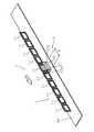
図1は、本発明に係る非接触給電システムの実施の形態1を用いた搬送システムの例を示す説明図であり、図2及び図3は、図1に示す搬送システムの搬送体の構成例を示す正面図及び側面図である。図1に示す搬送システム6は、自動車製造システムの例であり、複数の自動車を流れ作業的に製造する製造ラインであり、車体(以下、ワークと記載)を複数、一方向に搬送しつつ、部品の 取り付け及び検査等の作業が行なわれる。Hereinafter, the present invention will be described with reference to the drawings illustrating embodiments thereof.
(Embodiment 1)
FIG. 1 is an explanatory view showing an example of a transport system using the first embodiment of the non-contact power feeding system according to the present invention, and FIGS. 2 and 3 are configuration examples of the transport body of the transport system shown in FIG. It is the front view and side view which show. The conveyance system 6 shown in FIG. 1 is an example of an automobile manufacturing system, and is a production line for manufacturing a plurality of automobiles in a flowing manner, while conveying a plurality of vehicle bodies (hereinafter referred to as workpieces) in one direction, Parts are installed and inspected.
この搬送システム6は、複数(例えば15台)の搬送体3,3,…、非接触受電部1,1,…(図2,3)、及び昇降機器5,5,…をそれぞれ同数備え、所定の搬送路に沿って各搬送体3を搬送させる為の搬送装置4を備えている。
非接触給電システム7(図2)の為に、搬送路の一部に給電区間S,S,…が、他部に非給電区間N,N,…が設けられており、更に、給電区間S,S,…の個数と同数の非接触給電装置2,2,…(図2)が設けられている。
非接触受電部1(図2,3)は、空芯コイル11,11,…と共振コンデンサ121,121,…(図7参照)とを備え、非接触給電装置2(図2)は、コイル21,21,…とコア22,22,…とを備えている。以下では、搬送体3の搬送方向を前後方向(長さ方向)といい、搬送方向に略直交する水平方向を左右方向(幅方向)と記述する。The transport system 6 includes a plurality of (for example, 15)
For the non-contact power feeding system 7 (FIG. 2), power feeding sections S, S,... Are provided in a part of the conveyance path, and non-power feeding sections N, N,. , S,... Are provided in the same number as the number of non-contact
The non-contact power receiving unit 1 (FIGS. 2 and 3) includes air-
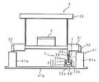
搬送体3は、4個の車輪32,32,…(図2,3)を前後左右に有する全長約6mの台車31を備え、ワークが載置される昇降台35を台車31上に備える。また、搬送体3には、昇降台35を昇降させる昇降機器5が設置してあり、更に、昇降機器5に給電する非接触受電部1が設置してある。即ち、搬送体3が搬送路を搬送されることにより、非接触受電部1が搬送路に沿って搬送される。 The
搬送装置4は、レール41,46を備え、レール41は、底部41bと、底部41bの左右両端部に並置された凸条部41a,41aとを有し、凸条部41a,41aに各搬送体3左右の車輪32,32,…が転接している。レール46は、レール41と略同様の構成である。レール41,46は、搬送体3の搬送路であり、それぞれ全長約130mを有する。
レール41上を搬送される搬送体3の昇降台35には、図示しないワークが載置され、レール46上を搬送される搬送体3にはワークが載置されない。つまり、レール41は各搬送体3の往路(作業用搬送路)であり、レール46は復路(返送用搬送路)である。レール46は例えば床面に敷設され、レール41はレール46の上側に離隔して設置されている。The conveying device 4 includes
A workpiece (not shown) is placed on the
更に、搬送装置4は、駆動ローラ42、従動ローラ43、モータ44及びチェーン45を備えている。駆動ローラ42及び従動ローラ43は、レール41の前後方向両端部に、ローラ42,43の軸方向を左右方向に略一致させて配置されている。チェーン45は、無端状に設けられ、レール41の上側及び下側を通って、ローラ42,43に懸吊されている。モータ44は、駆動ローラ42を略一定の所定速度で回転させる。
このような搬送装置4は、例えば商用電源から電線を介してモータ44駆動用の電力を得る。搬送体3,3,…は、互いに適長離隔してレール41上部側のチェーン45に着脱自在に掛止されている。Further, the transport device 4 includes a driving
Such a transport device 4 obtains electric power for driving the
モータ44により駆動ローラ42が回転した場合、チェーン45を介して従動ローラ43も回転し、チェーン45が白抜矢符方向に略一定速度で回転する。搬送体3,3,…は、チェーン45の回転により車輪32,32,…(図2,3)が転動して、レール41の一端側から他端側へ白抜矢符方向に略一定速度(例えば時速4km)でレール41上を搬送される。つまり、搬送体3,3,…は、自走せず、互いに数珠状につながれた状態でチェーン45に牽引されて移動する。また、搬送装置4は、レール41に係る構成と同様に、レール46に沿って矢符方向に搬送体3を搬送する為の図示しない駆動ローラ、従動ローラ、モータ及びチェーンを備えている。 When the driving
本実施の形態1における搬送路には、昇降機器5に対して給電する為の給電区間Sが、離散的に複数(例えば6箇所)設けてあり、給電区間S以外の搬送路は、昇降機器5に給電しない非給電区間Nである。作業者は、給電区間S,S,…の何れかに搬送体3が掛かっている場合に、つまり、搬送体3が給電区間Sを通過している間に、昇降台35上のワークに対して所定の作業を行なう。このとき、作業者は、作業内容及び作業の利便性等に応じて、昇降機器5を用いて昇降台35を昇降させ、ワークの上下方向の位置を調整する。ここで、作業者は、搬送体3に乗り込んで作業を行なっても良く、レール41の左右外側に設けられた図示しない作業台上にて作業を行なっても良い。 In the transport path in the first embodiment, a plurality of power feeding sections S for feeding power to the
搬送体3が給電区間Sを通過した後、次の給電区間Sに到達する迄、ワークに対して昇降機器5を用いる作業は行なわれない。つまり、本実施の形態1における各昇降機器5には、搬送体3が給電区間Sに掛かっている間のみ給電すれば良く、それ以外は給電する必要がない。尚、搬送体3が給電区間Sに掛かっていないときに、ワークに対して昇降機器5を用いない作業を行なうことが出来る。 After the
このように、給電区間S,S,…は、昇降台35に載置されたワークに対して、作業者が所定の作業を行なうべき作業区間でもあり、給電区間S,S,…は、往路であるレール41に関して設けられており、復路であるレール46に関しては設けられていない。この為、各搬送体3のレール46上における搬送速度は、レール41上における搬送速度より高速であることが望ましい。また、搬送体3は、給電区間Sで停止することはない。この為、各ワークに対する作業が効率良く行なわれる。 As described above, the power feeding sections S, S,... Are also work sections in which the operator should perform a predetermined work on the work placed on the
各搬送体3は、レール41の一端側にて昇降台35にワークが載置され、更に、各搬送体3自身がチェーン45に取り付けられる。この後、各搬送体3はレール41上を搬送され、給電区間S,S,…を通過する。レール41の他端側に到着したとき、各搬送体3は、昇降台35からワークが取り外され、更に各搬送体3自身がチェーン45から取り外されて、図示しない昇降装置で下段のレール46へ移送される。ワークが載置されていない各搬送体3は、レール46の一端側から他端側へレール46上を搬送され、他端側に到着したときに、上段のレール41の一端側へ移送される。レール41へ移送された各搬送体3は、昇降台35に新たなワークが載置され、チェーン45に取り付けられて、再びレール41上を搬送される。 Each
各非接触受電部1は、導線又は導体製のパイプを用いてロ字状に形成された空芯コイル11を複数(例えば10個)備える。搬送体3の台車31底面には、台車31底面からレール41の底部41b側へ突出するI字状のコイル取付部33が台車31の最前部から最後部にわたって設けてあり、各空芯コイル11はコイル固定具34でコイル取付部33に固定されることにより、レール41の底部41bに対向して台車31底面に吊設されている。尚、各空芯コイル11をコイル取付部33に固定する構成ではなく、非磁性体製のコイル取付部に巻装する構成でも良い。 Each non-contact
空芯コイル11,11,…は、搬送体3の側面側から見た各空芯コイル11の形状(以下、側面視の形状と記す)がロ字状になるような向きで、前後方向に互いに適長離隔されて略一直線に並置されている。つまり、搬送体3の正面/背面側から見た各空芯コイル11の形状(以下、正面視の形状と記す)がI字状になるよう配置されている。また、空芯コイル11,11,…は隣り合う空芯コイル11,11同士が直列に接続されており、非接触給電装置2(図2)のコイル21,21,…に誘導結合する。 The air core coils 11, 11,... Are oriented in the front-rear direction so that the shape of each air core coil 11 (hereinafter referred to as a side view shape) viewed from the side surface side of the
コイル取付部33は、アルミニウムで形成されており、台車31と空芯コイル11,11,…との間に介在して、空芯コイル11,11,…に係る漏れ磁束を遮蔽し、漏れ磁束の外部(例えば搬送体3に搭載された電気機器)への悪影響を低減する磁界遮蔽部としても機能する。尚、コイル取付部33で磁界を遮蔽する構成ではなく、台車31と空芯コイル11,11,…との間に介在する、例えば、非磁性体であり導電性の非鉄金属を用いてなる磁界遮蔽板を設けておく構成でも良い。 The
各給電区間Sには、非接触給電装置2が備えるコア22と、コア22に巻装されたコイル21とが設置されているが、各非給電区間Nには、コア22もコイル21も設置されていない。コア22は、図5(a)に示すように、正面視がコ字状に形成されたフェライト製であり、基部22a及び2つの脚部22b,22bを有し、コイル21は脚部22b,22bに巻装されている。尚、図5(b)に示すように、コア22の脚部22b,22bに代えて、コア22の基部22aにコイル211を巻装しても良い。 In each power feeding section S, a core 22 provided in the non-contact
図4は、本発明に係る非接触給電システム7の実施の形態1が備える非接触受電部1、及びその非接触受電部1に使用される非接触給電装置2の構成例を示す斜視図である。図4では、空芯コイル11,11,…と非接触給電装置2との位置関係を明示する為、搬送体3の図示を省略している。
給電区間Sにおけるレール41の底部41b上面には、細長矩形のコア取付板40が、コア取付板40の長さ方向が前後方向に略一致するようにして敷設してある。コア22は、正面視の形状がU字状になるような向きで、基部22aがコア取付板40に固定され、脚部22b,22bを上にして設置されている。FIG. 4 is a perspective view showing a configuration example of the non-contact
On the upper surface of the bottom 41b of the
空芯コイル11,11,…は、搬送体3が搬送されている場合に、コア22の脚部22b,22bの間を搬送方向(図4、白抜矢符方向)へ移動し、この場合、空芯コイル11とコイル21及びコア22とは、適長離隔しており、互いに接触しない。尚、空芯コイル11,11,…を樹脂モールドしたり、空芯コイル11,11,…に対して合成樹脂製のカバーを設けたりして、空芯コイル11,11,…を保護し、空芯コイル11とコイル21及びコア22等との直接的な当接を防止する構成でも良い。
コア22の長さ、コア22に対するコイル21の巻き数、各空芯コイル11の巻き数、長さ、空芯コイル11の個数及び離隔距離等は、昇降機器5が必要とする電力(例えば最大1.5kW〜2kW)、台車31の長さ等の仕様に応じて決定される。The air core coils 11, 11,... Move between the
The length of the core 22, the number of turns of the
図6は、非接触受電部1の空芯コイル11と非接触給電部のコア22との搬送方向の長さの関係を示す説明図である。搬送方向の長さaを有する各空芯コイル11は、隙間dを隔てて設けられており、上記搬送方向のコア22の長さbは、各空芯コイル11の長さa以下に設定されている。これにより、コア22からの受電に寄与しない、空芯コイル11間の隙間がコア22に掛かるのは、1ヶ所以下となり、非接触受電部1の受電能力の低下を抑制することが出来る。 FIG. 6 is an explanatory diagram illustrating a relationship in length in the transport direction between the air-
図7は、本発明に係る非接触給電システム7の実施の形態1の回路構成を示すブロック図である。この非接触給電システム7に使用される非接触給電装置2は、コイル21の他に補償コンデンサ23及び高周波電源装置24を備えている。コイル21及び補償コンデンサ23は、高周波電源装置24に直列に接続されている。
高周波電源装置24は、商用電源に接続され、AC200V、60Hzの商用電源を整流し平滑化して直流に変換した後、変換した直流をインバータ(DC−AC変換器)により高周波交流(例えば20kHz)に変換し、変換した高周波交流をイミタンス変換回路により高周波の定電流としてコイル21に通流させる。FIG. 7 is a block diagram showing a circuit configuration of the first embodiment of the non-contact
The high frequency
高周波電源装置24により非接触給電装置2のコイル21に高周波電流が通流されると、コイル21の周囲に、時間的に変化する磁束が形成される。搬送体3(図1,2)が搬送されているとき、各空芯コイル11は、コイル21の周囲に生じる磁束に対して搬送方向に順次的に鎖交する。非接触受電部1は、コイル21の周囲に生じた磁束が空芯コイル11,11,…に鎖交することにより、空芯コイル11,11,…に発生した誘導起電力を受電する。 When a high frequency current is passed through the
非接触受電部1は、空芯コイル11,11,…の他に受電部12と出力端子10とを備え、また、昇降機器5は、直流を交流に変換するインバータ機能を有するモータドライバ51と、交流モータであるモータ52とを備えている。非接触受電部1の出力端子10には、DCバスDBを介してモータドライバ51が接続してあり、モータドライバ51は、負荷であるモータ52を駆動して、昇降台35を昇降させる。 The non-contact
受電部12は、空芯コイル11,11,…と同数の共振コンデンサ121,121,…を備え、空芯コイル11,11,…と共振コンデンサ121,121,…とは、それぞれ直列に接続されて直列共振回路120を構成している。また、受電部12は、直列共振回路120の出力側に接続され、交流を全波整流するダイオードブリッジを用いた整流回路122と、整流回路122の出力電圧を平滑する電解コンデンサである平滑コンデンサ123とを備え、平滑コンデンサ123の両端子が非接触受電部1の出力端子10,10に接続されている。 The
非接触受電部1は、また、商用交流電源54又は図示しない電池等の外部の電源を、整流回路122の出力端子(平滑コンデンサ123の両端子)に接続する接続回路を備えている。接続回路は、コンセント56又はトロリー(集電装置)と、コンセント56又はトロリーを入力端子とし、交流を全波整流するダイオードブリッジを用いた整流回路(第2整流回路)55とを備え、整流回路55の出力端子は、整流回路122の出力端子に並列に接続されている。 The non-contact
直列共振回路120は、空芯コイル11,11,…がコイル21に誘導結合する為に、コイル21を流れる高周波電流に共振するよう構成されている。この場合、直列共振回路120は、空芯コイル11,11,…に誘起された電力を受けて、高周波交流の定電圧源として機能する。尚、直列共振回路120をコイル21を流れる高周波電流に完全に共振させる必要はない。 The
直列共振回路120の出力(交流定電圧)は、整流回路122で全波整流され、整流回路122から出力された直流は、平滑コンデンサ123で平滑される。非接触受電部1は、平滑コンデンサ123で平滑された直流を、出力端子10及びDCバスDBを通じて、モータドライバ51へ供給する。モータドライバ51は、供給された直流を交流に変換して、モータ52へ供給する。 The output (AC constant voltage) of the series
ところで、非接触給電装置2が補償コンデンサ23を備えない場合、コイル21をコア22に巻装してあるので、コイル21のインダクタンスが高周波電源装置24内の共振回路(イミタンス変換回路)の定数より大きくなり、共振状態が維持できなくなり、非接触受電部1の受電効率が低下する。つまり、補償コンデンサ23は、非接触給電装置2のインダクタンスを所定値以下に維持して、非接触受電部1の受電効率の低下を防止する為に備えている。 By the way, when the non-contact
以上のような非接触給電システム7では、搬送体3が給電区間Sに掛かっているときに、非接触受電部1が、非接触給電装置2から給電され(受電し)て、負荷である昇降機器5へ給電する。また、昇降機器5への給電時に搬送体3が停止する必要がなく、移動中に給電可能である。これにより、自動車製造システムの自動車製造効率が向上する。
また、コンセント56に商用交流電源54又は図示しない電池等の外部の電源を接続している場合は、整流回路55,122の各出力電圧の高い方の電圧が、出力端子10及びDCバスDBを通じて、モータドライバ51へ供給される。この場合、出力電圧が低い方の整流回路55,122は、その構成するダイオードブリッジにより電流の逆流を阻止することができる。In the non-contact
Further, when a commercial
(実施の形態2)
図8は、本発明に係る非接触給電システムの実施の形態2の回路構成を示すブロック図である。
この非接触給電システム7aは、非接触受電部1aが、商用交流電源54又は図示しない電池等の外部の電源を、整流回路122の入力端子に接続する接続回路を備えている。接続回路は、コンセント56又はトロリーと、コンセント56又はトロリーの2つの端子を一方の接点とし、直列共振回路120の2つの出力端子を他方の接点として、整流回路122の入力端子に切替え接続する手動の切替スイッチ57とを備えている。(Embodiment 2)
FIG. 8 is a block diagram showing a circuit configuration of
In the non-contact power supply system 7 a, the non-contact power receiving unit 1 a includes a connection circuit that connects an external power source such as a commercial
以上のような非接触給電システム7aでは、コンセント56に商用交流電源54又は図示しない電池等の外部の電源を接続している場合は、交流電力が整流回路122で整流され、又は直流電力がそのまま整流回路122を通流して、出力端子10及びDCバスDBを通じて、モータドライバ51へ供給される。この場合、直列共振回路120側が、整流回路122及びコンセント56に接続されていないので、電流の逆流は生じない。非接触給電システム7aのその他の構成及び動作は、上述した本発明に係る非接触給電システムの実施の形態1の構成(図1〜7)及び動作と同様であるので、説明を省略する。 In the non-contact power supply system 7a as described above, when the commercial
(実施の形態3)
図9は、本発明に係る非接触給電システムの実施の形態3の回路構成を示すブロック図である。
この非接触給電システム7bは、非接触受電部1bが、商用交流電源54又は図示しない電池等の外部の電源を、整流回路122の入力端子に接続する接続回路を備えている。(Embodiment 3)
FIG. 9 is a block diagram showing a circuit configuration of a third embodiment of the non-contact power feeding system according to the present invention.
In the non-contact
接続回路は、コンセント56又はトロリーと、コンセント56又はトロリーの端子を一方の接点とし、直列共振回路120の出力端子を他方の接点として、整流回路122の入力端子に切替え接続するリレー接点ry1,ry2と,リレー接点ry1,ry2(接点回路)のリレー駆動回路RY(接点回路)とを備えている。
また、接続回路は、コンセント56又はトロリーに接続された電源の電圧を検出する電圧検出回路(検出回路)58を備え、電圧検出回路58は、電源の電圧を検出しているときは、リレー駆動回路RYを作動させる。The connection circuit is a relay contact ry1, ry2 that switches and connects to the input terminal of the
In addition, the connection circuit includes a voltage detection circuit (detection circuit) 58 that detects the voltage of the power source connected to the
以上のような非接触給電システム7bでは、電圧検出回路58は、電源の電圧を検出しているときは、リレー接点ry1,ry2がコンセント56又はトロリーと整流回路122の入力端子とを接続するように、リレー駆動回路RYを作動させる。
リレー接点ry1,ry2がコンセント56又はトロリーと整流回路122の入力端子とを接続している間は、交流電力が整流回路122で整流され、又は直流電力がそのまま整流回路122を通流して、出力端子10及びDCバスDBを通じて、モータドライバ51へ供給される。この場合、直列共振回路120側が、整流回路122及びコンセント56に接続されていないので、電流の逆流は生じない。本非接触給電システム7bのその他の構成及び動作は、上述した本発明に係る非接触給電システムの実施の形態1の構成(図1〜7)及び動作と同様であるので、説明を省略する。In the non-contact
While the relay contacts ry1 and ry2 connect the
1,1a,1b 非接触受電部
2 非接触給電装置
7,7a,7b 非接触給電システム
11 空芯コイル
21 コイル
22 コア
24 高周波電源装置
51 モータドライバ
52 モータ(負荷)
54 商用交流電源
55 整流回路(接続回路)
56 コンセント(接続回路)
57 切替スイッチ(接続回路)
58 電圧検出回路(接続回路)
120 直列共振回路
121 共振コンデンサ
122 整流回路
123 平滑コンデンサ
RY リレー駆動回路(接点回路)
ry1,ry2 リレー接点(接点回路)DESCRIPTION OF
54 Commercial
56 Outlet (connection circuit)
57 selector switch (connection circuit)
58 Voltage detection circuit (connection circuit)
120 Series
ry1, ry2 relay contact (contact circuit)
Claims (4)
Translated fromJapanese前記非接触受電部に外部の電源を並列に接続する為の接続回路を備えることを特徴とする非接触給電システム。In a non-contact power feeding system including a non-contact power receiving unit that generates an induced electromotive force by an alternating current supplied to a power supply line, rectifies the induced electromotive force by a rectifier circuit, and supplies a constant voltage to a load. ,
A non-contact power feeding system comprising a connection circuit for connecting an external power source in parallel to the non-contact power receiving unit.
Priority Applications (1)
| Application Number | Priority Date | Filing Date | Title |
|---|---|---|---|
| JP2005271093AJP2007082383A (en) | 2005-09-16 | 2005-09-16 | Noncontact power supply system |
Applications Claiming Priority (1)
| Application Number | Priority Date | Filing Date | Title |
|---|---|---|---|
| JP2005271093AJP2007082383A (en) | 2005-09-16 | 2005-09-16 | Noncontact power supply system |
Publications (1)
| Publication Number | Publication Date |
|---|---|
| JP2007082383Atrue JP2007082383A (en) | 2007-03-29 |
Family
ID=37942060
Family Applications (1)
| Application Number | Title | Priority Date | Filing Date |
|---|---|---|---|
| JP2005271093APendingJP2007082383A (en) | 2005-09-16 | 2005-09-16 | Noncontact power supply system |
Country Status (1)
| Country | Link |
|---|---|
| JP (1) | JP2007082383A (en) |
Cited By (4)
| Publication number | Priority date | Publication date | Assignee | Title |
|---|---|---|---|---|
| JP2009119965A (en)* | 2007-11-13 | 2009-06-04 | Asyst Technologies Japan Inc | Electric power supply system |
| KR101188771B1 (en) | 2008-07-04 | 2012-10-10 | 무라다기카이가부시끼가이샤 | Traveling vehicle system |
| EP3428659A1 (en)* | 2017-07-12 | 2019-01-16 | LEM Intellectual Property SA | Contactless voltage transducer |
| JPWO2024176424A1 (en)* | 2023-02-24 | 2024-08-29 |
Citations (9)
| Publication number | Priority date | Publication date | Assignee | Title |
|---|---|---|---|---|
| JPH0898438A (en)* | 1994-09-16 | 1996-04-12 | Hitachi Kiden Kogyo Ltd | Method and apparatus for non-contact power feeding in magnetic levitation transportation apparatus |
| JP2001119806A (en)* | 1999-10-13 | 2001-04-27 | Toyota Autom Loom Works Ltd | Noncontact power supply system and receiving device used in the system |
| JP2002058179A (en)* | 2000-08-10 | 2002-02-22 | Toyota Industries Corp | Mobile unit power supply circuit of noncontact feeder apparatus |
| JP2002354712A (en)* | 2001-05-22 | 2002-12-06 | Shinko Electric Co Ltd | Noncontact power feeder device |
| JP2003079074A (en)* | 2001-08-31 | 2003-03-14 | Daifuku Co Ltd | Transfer equipment |
| JP2003341390A (en)* | 2002-05-24 | 2003-12-03 | Toyota Industries Corp | Track carriage system of contactless feed system |
| JP2004072832A (en)* | 2002-08-02 | 2004-03-04 | Hitachi Kiden Kogyo Ltd | Non-contact power feeding method |
| JP2004135405A (en)* | 2002-10-09 | 2004-04-30 | Mitsubishi Heavy Ind Ltd | Power feeder for steeply sloped conveyance carriage |
| JP2005094862A (en)* | 2003-09-12 | 2005-04-07 | Tsubakimoto Chain Co | Contactless power feeding method and apparatus |
- 2005
- 2005-09-16JPJP2005271093Apatent/JP2007082383A/enactivePending
Patent Citations (9)
| Publication number | Priority date | Publication date | Assignee | Title |
|---|---|---|---|---|
| JPH0898438A (en)* | 1994-09-16 | 1996-04-12 | Hitachi Kiden Kogyo Ltd | Method and apparatus for non-contact power feeding in magnetic levitation transportation apparatus |
| JP2001119806A (en)* | 1999-10-13 | 2001-04-27 | Toyota Autom Loom Works Ltd | Noncontact power supply system and receiving device used in the system |
| JP2002058179A (en)* | 2000-08-10 | 2002-02-22 | Toyota Industries Corp | Mobile unit power supply circuit of noncontact feeder apparatus |
| JP2002354712A (en)* | 2001-05-22 | 2002-12-06 | Shinko Electric Co Ltd | Noncontact power feeder device |
| JP2003079074A (en)* | 2001-08-31 | 2003-03-14 | Daifuku Co Ltd | Transfer equipment |
| JP2003341390A (en)* | 2002-05-24 | 2003-12-03 | Toyota Industries Corp | Track carriage system of contactless feed system |
| JP2004072832A (en)* | 2002-08-02 | 2004-03-04 | Hitachi Kiden Kogyo Ltd | Non-contact power feeding method |
| JP2004135405A (en)* | 2002-10-09 | 2004-04-30 | Mitsubishi Heavy Ind Ltd | Power feeder for steeply sloped conveyance carriage |
| JP2005094862A (en)* | 2003-09-12 | 2005-04-07 | Tsubakimoto Chain Co | Contactless power feeding method and apparatus |
Cited By (9)
| Publication number | Priority date | Publication date | Assignee | Title |
|---|---|---|---|---|
| JP2009119965A (en)* | 2007-11-13 | 2009-06-04 | Asyst Technologies Japan Inc | Electric power supply system |
| KR101188771B1 (en) | 2008-07-04 | 2012-10-10 | 무라다기카이가부시끼가이샤 | Traveling vehicle system |
| US8519570B2 (en) | 2008-07-04 | 2013-08-27 | Murata Machinery, Ltd. | Traveling vehicle system |
| EP3428659A1 (en)* | 2017-07-12 | 2019-01-16 | LEM Intellectual Property SA | Contactless voltage transducer |
| WO2019011896A1 (en)* | 2017-07-12 | 2019-01-17 | Lem Intellectual Property Sa | Contactless voltage transducer |
| US11137423B2 (en) | 2017-07-12 | 2021-10-05 | Lem International Sa | Contactless voltage transducer |
| JPWO2024176424A1 (en)* | 2023-02-24 | 2024-08-29 | ||
| WO2024176424A1 (en)* | 2023-02-24 | 2024-08-29 | 三菱電機株式会社 | Electric motor drive device and air conditioner |
| JP7721037B2 (en) | 2023-02-24 | 2025-08-08 | 三菱電機株式会社 | Electric motor drive device and air conditioner |
Similar Documents
| Publication | Publication Date | Title |
|---|---|---|
| JP4208757B2 (en) | Contactless power supply system | |
| KR0134898B1 (en) | Conveying system | |
| JP5437650B2 (en) | Non-contact power feeding device | |
| CN108237921B (en) | Conveying trolley | |
| CN105035673A (en) | Conjoined double-layer halved belt type sorting machine | |
| CN106477402A (en) | Elevator Wireless Power Transmission System | |
| TW548212B (en) | Unmanned transportation-vehicle system | |
| KR102290659B1 (en) | Automated Transfer Facility | |
| Boys et al. | IPT fact sheet series: no. 1–basic concepts | |
| JP2010040699A (en) | Noncontacting feed device | |
| CN116094189A (en) | Non-contact power supply equipment, impedance adjustment method of non-contact power supply equipment, and impedance adjustment procedure of non-contact power supply equipment | |
| JP3491179B2 (en) | Non-contact power receiving device | |
| JP2007082383A (en) | Noncontact power supply system | |
| JPH08308151A (en) | Noncontacting power distribution system | |
| JP2006211804A (en) | Noncontact power supply system | |
| JP3522413B2 (en) | Non-contact power supply device for ground moving objects | |
| JP2014033524A (en) | Non-contact power supply system for unmanned carrier | |
| JP5413849B2 (en) | Induction power receiving circuit | |
| JP5170451B2 (en) | Induction power receiving circuit | |
| JPH08308150A (en) | Noncontact power distribution system | |
| JP3988718B2 (en) | Method for adjusting inductance of induction line of contactless power supply equipment | |
| JP4640035B2 (en) | Contactless power supply equipment | |
| JPH06153305A (en) | Feeder holder | |
| JP4416726B2 (en) | Power supply device and transfer system | |
| JP3380886B2 (en) | Contactless power supply system for mobile objects |
Legal Events
| Date | Code | Title | Description |
|---|---|---|---|
| A621 | Written request for application examination | Free format text:JAPANESE INTERMEDIATE CODE: A621 Effective date:20070914 | |
| A131 | Notification of reasons for refusal | Free format text:JAPANESE INTERMEDIATE CODE: A131 Effective date:20100629 | |
| A521 | Written amendment | Free format text:JAPANESE INTERMEDIATE CODE: A523 Effective date:20100825 | |
| A131 | Notification of reasons for refusal | Free format text:JAPANESE INTERMEDIATE CODE: A131 Effective date:20110301 | |
| A02 | Decision of refusal | Free format text:JAPANESE INTERMEDIATE CODE: A02 Effective date:20111018 |