JP2007079204A - Autofocus device, camera and lens barrel - Google Patents
Autofocus device, camera and lens barrelDownload PDFInfo
- Publication number
- JP2007079204A JP2007079204AJP2005268061AJP2005268061AJP2007079204AJP 2007079204 AJP2007079204 AJP 2007079204AJP 2005268061 AJP2005268061 AJP 2005268061AJP 2005268061 AJP2005268061 AJP 2005268061AJP 2007079204 AJP2007079204 AJP 2007079204A
- Authority
- JP
- Japan
- Prior art keywords
- lens
- focus
- photographing lens
- contrast
- camera
- Prior art date
- Legal status (The legal status is an assumption and is not a legal conclusion. Google has not performed a legal analysis and makes no representation as to the accuracy of the status listed.)
- Pending
Links
Images


Landscapes
- Focusing (AREA)
- Automatic Focus Adjustment (AREA)
- Studio Devices (AREA)
Abstract
Description
Translated fromJapanese本発明は、撮影光学系の焦点を自動調節する装置と、その自動焦点調節装置を備えたカメラ、並びに前記カメラに装着可能なレンズ鏡筒に関する。 The present invention relates to a device that automatically adjusts the focus of a photographing optical system, a camera including the automatic focus adjusting device, and a lens barrel that can be attached to the camera.
撮影レンズを通る一対の被写体光を一対の光電変換素子列へ導き、一対の被写体像の位相差を検出して撮影レンズの焦点調節状態を検出する位相差検出方式の焦点検出装置と、撮影レンズにより結像された被写体像を撮像する撮像素子の出力からコントラストを検出し、コントラストにより撮影レンズの焦点調節状態を検出するコントラスト方式の焦点検出装置とを併用するハイブリッドAF(オートフォーカス)カメラが知られている(例えば、特許文献1参照)。
この種のハイブリッドAFカメラでは、合焦位置近傍まで位相差検出方式により焦点検出を行って撮影レンズを駆動し、合焦位置近傍に到達した後はコントラスト方式により焦点検出を行って撮影レンズを駆動しており、合焦精度の向上と合焦時間の短縮を図っている。A focus detection device of a phase difference detection method that detects a focus adjustment state of a photographing lens by guiding a pair of subject light passing through the photographing lens to a pair of photoelectric conversion element arrays and detecting a phase difference between the pair of subject images, and a photographing lens A hybrid AF (autofocus) camera that uses a contrast-type focus detection device that detects contrast from the output of an image sensor that captures an image of a subject image formed by the image sensor and detects the focus adjustment state of the photographing lens based on the contrast is known. (For example, refer to Patent Document 1).
In this type of hybrid AF camera, the focus detection is performed by the phase difference detection method to the vicinity of the in-focus position to drive the photographing lens, and after reaching the vicinity of the in-focus position, the focus detection is performed by the contrast method to drive the photographing lens. Therefore, the focus accuracy is improved and the focus time is shortened.
この出願の発明に関連する先行技術文献としては次のものがある。
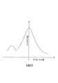
しかしながら、ハイブリッドAFを備えたレンズ交換式カメラにおいて、コントラスト方式のみによりAFを行う場合に、撮影レンズの光学性能によっては、図5に示すようにコントラスト値に周波数成分による擬似ピークが出現する場合があり、単純に山登り方式によるコントラストAFを行うと、このような擬似ピークに合焦してしまうことがある。かといって、常に全域スキャン方式によるコントラストAFを行うと合焦時間が長くなるという問題がある。 However, in an interchangeable lens camera equipped with hybrid AF, when AF is performed only by the contrast method, a pseudo peak due to a frequency component may appear in the contrast value as shown in FIG. 5 depending on the optical performance of the photographing lens. Yes, if contrast AF is simply performed by the hill-climbing method, such a pseudo peak may be focused. However, there is a problem that when the contrast AF is always performed by the whole area scanning method, the focusing time becomes long.
(1) 請求項1の発明は、撮影レンズによる被写体像を撮像する撮像手段で得られる画像信号のコントラスト状態に基づいて撮影レンズの焦点調節状態を検出する焦点検出手段を備えたカメラに適用され、撮影レンズの特性に関する情報に基づいて、焦点調節状態を検出する際の撮影レンズの駆動方式を選択する駆動制御手段を備える。
(2) 請求項2の発明は、撮影レンズにより結像された被写体像を撮像し、撮影レンズを駆動する間に撮像信号のコントラスト状態に基づいて撮影レンズの焦点調節状態を検出するとともに、撮影レンズの特性を入手し、撮影レンズの特性に応じて撮影レンズの駆動方式を選択し、焦点調節状態の検出結果に基づいて撮影レンズを駆動する。
(3) 請求項3の発明は、撮影レンズの駆動方式として、焦点評価値を演算しながら焦点調節レンズをその移動範囲の全域にわたって所定の移動量きざみで駆動し、焦点評価値が最大となる位置を検出してその位置に焦点調節レンズを設定する全域スキャン方式と、焦点評価値が大きくなる方向に焦点調節レンズを所定の移動量ずつ駆動し、焦点評価値のピーク位置まで到達したらその位置に焦点調節レンズを設定する山登り方式とを有し、撮影レンズの特性に応じて全域スキャン方式または山登り方式を選択する。
(4) 請求項4の発明は、被写体像のコントラストが最大となるレンズ位置以外に擬似ピークが出現する特性の撮影レンズに対しては全域スキャン方式を選択する。
(5) 請求項5の発明は、焦点評価値がピークとなるレンズ位置の付近では前記所定の移動量を他のレンズ位置よりも少なくする。
(6) 請求項6の発明は、カメラに、上記請求項2〜5のいずれか1項に記載の自動焦点調節装置を備えたものである。
(7) 請求項7の発明は、上記請求項1または請求項6に記載のカメラに装着可能なレンズ鏡筒であって、撮影レンズの特性に関する情報を記憶する記憶手段と、前記特性に関する情報をカメラに出力する出力手段とを備える。(1) The invention of claim 1 is applied to a camera including a focus detection unit that detects a focus adjustment state of a photographing lens based on a contrast state of an image signal obtained by an imaging unit that captures a subject image by the photographing lens. Drive control means for selecting a driving method of the photographing lens when detecting the focus adjustment state based on information on the characteristics of the photographing lens.
(2) According to the second aspect of the present invention, the subject image formed by the photographic lens is imaged, and the focus adjustment state of the photographic lens is detected based on the contrast state of the imaging signal while the photographic lens is driven. The lens characteristics are obtained, the photographing lens driving method is selected according to the characteristics of the photographing lens, and the photographing lens is driven based on the detection result of the focus adjustment state.
(3) According to the third aspect of the present invention, the focus evaluation value is maximized by driving the focus adjustment lens with a predetermined amount of movement over the entire movement range while calculating the focus evaluation value as a driving method of the photographing lens. The whole area scan method that detects the position and sets the focus adjustment lens at that position, and the focus adjustment lens is driven by a predetermined amount of movement in the direction in which the focus evaluation value increases, and when it reaches the peak position of the focus evaluation value, that position And a hill-climbing method for setting a focus adjustment lens, and a whole-area scanning method or a hill-climbing method is selected according to the characteristics of the photographing lens.
(4) The invention of claim 4 selects the whole-area scanning method for a photographing lens having a characteristic in which a pseudo peak appears in addition to the lens position where the contrast of the subject image is maximized.
(5) In the invention according to claim 5, the predetermined movement amount is made smaller than that of other lens positions in the vicinity of the lens position where the focus evaluation value reaches a peak.
(6) The invention of claim 6 is a camera comprising the automatic focus adjustment apparatus according to any one of claims 2 to 5.
(7) The invention according to claim 7 is a lens barrel that can be attached to the camera according to claim 1 or 6, wherein the storage means stores information relating to characteristics of the photographing lens, and information relating to the characteristics. Output means for outputting to the camera.
本発明によれば、撮影レンズの光学特性に応じた最適なコントラストAF方式を選択することができる。 According to the present invention, it is possible to select an optimum contrast AF method according to the optical characteristics of the taking lens.
本願発明を、撮影レンズを通る一対の被写体光を一対の光電変換素子列へ導き、一対の被写体像の位相差を検出して撮影レンズの焦点調節状態を検出する位相差検出方式の焦点検出装置と、撮影レンズにより結像された被写体像を撮像する撮像素子の出力からコントラストを検出し、コントラストにより撮影レンズの焦点調節状態を検出するコントラスト方式の焦点検出装置とを併用するハイブリッドAF方式のレンズ交換可能なカメラに適用した一実施の形態を説明する。 The present invention is a phase difference detection type focus detection device that detects a focus adjustment state of a photographing lens by guiding a pair of subject light passing through the photographing lens to a pair of photoelectric conversion element arrays and detecting a phase difference between the pair of subject images. And a hybrid AF type lens used in combination with a contrast type focus detection device that detects the contrast from the output of an image sensor that captures the subject image formed by the photographic lens and detects the focus adjustment state of the photographic lens based on the contrast An embodiment applied to a replaceable camera will be described.
なお、本願発明は、ハイブリッドAFカメラに限定されず、コントラスト方式により撮影レンズの焦点調節を行うすべてのレンズ交換可能なカメラに適用することができる。 The present invention is not limited to a hybrid AF camera, but can be applied to all interchangeable cameras that adjust the focus of a photographing lens using a contrast method.
図1は一実施の形態のハイブリッドAFカメラの構成を示す。カメラボディ10は撮像素子20、ペンタプリズム30、測光素子40、リレーレンズ50、接眼部60、クイックリターンミラー70、サブミラー80、固定ミラー90、位相差検出方式AFセンサー100を内蔵している。CCDやCMOSなどの撮像素子20は、後述する撮影レンズ120a、120b、120cにより結像された被写体像を電気信号に変換して出力する。なお、撮像素子20の受光面には図示しない赤外カットフィルターと光学的ローパスフィルターが配置されている。 FIG. 1 shows a configuration of a hybrid AF camera according to an embodiment. The
ペンタプリズム30、リレーレンズ50および接眼部60は光学ファインダーを構成する。測光素子40は、シャッター速度や絞りを決定するために被写界を測光して測光値を出力する。クイックリターンミラー70およびサブミラー80は通常は撮影レンズ120の光路中に置かれ、撮影レンズ120を通った被写体からの光がクイックリターンミラー70に反射されて光学ファインダー30〜60へ導かれるとともに、被写体光の一部がクイックリターンミラー70を透過してサブミラー80と固定ミラー90に反射され、位相差検出方式のAFセンサー100へ導かれる。 The
AFセンサー100は焦点検出光学系と一対の光電変換素子列(CCD)を有し、焦点検出光学系により一対の光電変換素子列上に一対の被写体像を結像させて一対の被写体像の像ずれ量を検出する。 The
撮像素子20による撮像時(露光時)とコントラストAFを行うときは、クイックリターンミラー70およびサブミラー80が撮影レンズ120の光路から退避され、撮影レンズ120を通過した被写体光が撮像素子20へ導かれる。 When performing imaging with the image sensor 20 (exposure) and contrast AF, the
カメラボディ10には脱着可能な撮影レンズ鏡筒110が装着されている。撮影レンズ鏡筒110は撮影レンズ120a、120b、120c、焦点調節レンズ駆動用モーター130、絞り140、レンズメモリ150などを内蔵している。モーター130は撮影レンズ内の焦点調節用レンズ120bを光軸方向に移動する。また、レンズメモリ150には撮影レンズ120の特性データなどが記憶されている。 A detachable
カメラボディ10はまた、ボディCPU200を備えている。ボディCPU200は、マイクロコンピューターのソフトウエア形態により構成されるCCD制御部220、コントラスト検出部230、デフォーカス量演算部240、レンズ目標位置演算部250、レンズ駆動信号演算部260を備えている。なお、210はシャッターレリーズボタンの半押しスイッチである。 The
CCD制御部220はAFセンサー100の光電変換素子列(CCD)の電荷蓄積制御を行い、デフォーカス量演算部240はAFセンサー100で検出した像ずれ量に基づいて撮影レンズ120のデフォーカス量を演算する。レンズ目標位置演算部250はデフォーカス量に基づいて焦点調節レンズ120bの目標位置を演算し、レンズ駆動信号演算部260は目標位置まで焦点調節レンズ120bを駆動するための信号を演算する。さらに、コントラスト検出部230は撮像素子20の画像出力に基づいて被写体像のコントラストを求め、焦点評価値を演算する。 The
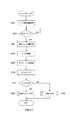
図2は一実施の形態のコントラストAFプログラムを示すフローチャート、図3は全域スキャン方式コントラストAFプログラムを示すフローチャート、図4は山登り方式コントラストAFプログラムを示すフローチャートである。これらのフローチャートにより、一実施の形態のコントラストAF動作を説明する。 FIG. 2 is a flowchart showing a contrast AF program according to an embodiment, FIG. 3 is a flowchart showing a whole-area scan type contrast AF program, and FIG. 4 is a flowchart showing a hill-climbing type contrast AF program. The contrast AF operation according to the embodiment will be described with reference to these flowcharts.
ハイブリッドAFカメラにおいて、撮像素子20で撮像した画像をLCDモニター(不図示)に表示しながら静止画を撮影したり、あるいはLCDモニターで画像を見ながら動画を撮影したい場合には、コントラスト方式AFを選択して撮影レンズ120の焦点調節を行う。 In a hybrid AF camera, if you want to shoot a still image while displaying an image captured by the
ステップ101においてカメラボディ10に装着されている撮影レンズ鏡筒110から撮影レンズ120の識別情報を取得する。撮影レンズ鏡筒110にはレンズメモリ150が設けられており、カメラボディ10のマウント部接点(不図示)を介して撮影レンズ120のレンズメモリ150から種々の情報を入力する。レンズ情報には焦点距離、Fナンバーなどのレンズ固有の特性値の他に、山登り方式AFに対する適、不適を示す識別記号aが含まれる。 In
撮影レンズの光学性能において、図5に示すように、被写体のコントラストが最大となるレンズ位置以外の位置に擬似ピークが出現する撮影レンズは、山登り方式により焦点調節を行うと、擬似ピークを被写体のコントラストのピークと誤認して合焦することがある。したがって、図5に示すような擬似ピークが出現する光学特性の撮影レンズは山登り方式AFには不適であり、記号aを付して区別する。 As shown in FIG. 5, in the optical performance of the photographic lens, a photographic lens in which a pseudo peak appears at a position other than the lens position where the contrast of the subject is maximum is obtained. May be mistaken for the peak of contrast and focus. Therefore, a photographing lens having an optical characteristic in which a pseudo peak appears as shown in FIG. 5 is not suitable for the hill-climbing AF, and is distinguished by attaching the symbol a.
ステップ102でスイッチ210によりシャッターレリーズボタンが半押しされたか否かを確認し、シャッターレリーズボタンが半押しされるとステップ103へ進み、撮影レンズ鏡筒110からフォーカシングレンズ120bの現在の位置を取得する。ステップ104で位相差検出用AFセンサー100のCCD制御を行い、続くステップ105ではAFセンサー100で検出した像ずれ量に基づいてデフォーカス量を演算し、メモリ(不図示)に記憶する。このデフォーカス量により山登り方式AF時のフォーカシングレンズ120bの駆動方向を決定する。 In
ステップ106においてクイックリターンミラー70とサブミラー80のミラーアップを行い、撮像素子20による撮像を開始する。次に、ステップ107で撮影レンズ120の種類が山登り方式AFに適さない識別記号aが付された種類であるか否かを確認し、識別記号aが付された種類であればステップ108へ進んで全域スキャン方式のコントラストAFを行い、識別記号aが付されていない種類であればステップ109へ進んで山登り方式のコントラストAFを行う。 In step 106, the
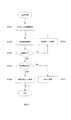
識別記号aの付された山登り方式AFに適さない撮影レンズ鏡筒110が装着されている場合には、ステップ108で図3に示す全域スキャン方式によるレンズ駆動を行う。全域スキャン方式とは、焦点評価値を演算しながら焦点調節レンズ120bをその移動範囲の全域にわたって所定の移動量きざみで駆動し、焦点評価値がピークとなる位置を検出してその位置に焦点調節レンズ120bを設定するコントラストAF方式である。 If the photographing
図3のステップ201においてフォーカシングレンズ120bを無限端へ移動する。この一実施の形態では全域スキャン方式AFを実行する場合に無限端から至近端へフォーカシングレンズ120bを移動させる例を示すが、フォーカシングレンズ120bの位置が至近端に近い場合には至近端から無限端へ移動させてもよい。 In step 201 of FIG. 3, the focusing
ステップ202では撮像素子20の画像出力に基づいて被写体像のコントラストを求め、焦点評価値を演算する。続くステップ203で無限端から至近端までの全域において焦点評価値の演算を終了したか否かを確認し、終了していない場合はステップ204へ進む。ステップ204ではフォーカシングレンズ120bを所定の移動量だけ駆動する。 In
ここで、全域スキャン方式AFにおけるフォーカシングレンズ120bの所定の移動量を一定値とせず、コントラストがピークとなるレンズ位置の付近では所定の移動量を他のレンズ位置よりも少なくし、コントラストのピークを正確に検出できるようにする。さらに、焦点距離や撮影距離などのレンズ情報により所定の移動量を変えてもよい。 Here, the predetermined movement amount of the focusing
無限端から至近端までの全域において焦点評価値の演算を終了したらステップ205へ進み、演算の結果、最大の焦点評価値が得られたか、つまり焦点検出が可能か否かを確認し、焦点検出可能な場合はステップ206へ進み、最大の焦点評価値を示す位置を合焦位置としてフォーカシングレンズ120bを駆動する。一方、焦点検出不能な場合はステップ207へ進み、フォーカシングレンズ120bをスキャン動作させる。スキャン動作により焦点が検出されればその合焦位置へフォーカシングレンズ120bを駆動し、検出できなければスキャン動作を終了する。 When the calculation of the focus evaluation value is completed in the entire region from the infinite end to the closest end, the process proceeds to step 205, where it is confirmed whether the maximum focus evaluation value is obtained as a result of the calculation, that is, whether focus detection is possible. If it can be detected, the process proceeds to step 206, and the focusing
一方、識別記号aの付されていない山登り方式AFに適した撮影レンズ鏡筒110が装着されている場合には、図2のステップ109で図4に示す山登り方式によるレンズ駆動を行う。山登り方式とは、焦点評価値が大きくなる方向に焦点調節レンズ120bを所定の移動量ずつ駆動し、焦点評価値のピーク位置まで到達したと判定されたらその位置に焦点調節レンズ120bを設定するコントラストAF方式である。 On the other hand, when the photographing
図4のステップ301においてメモリからデフォーカス量を読み出し、フォーカシングレンズ120bの駆動方向を決定する。ステップ302で撮像素子20の画像出力に基づいて被写体像のコントラストを求め、焦点評価値を演算する。 In
ステップ303でコントラストのピーク位置を超えたか否かを確認し、超えていない場合はステップ304へ進む。ステップ304ではフォーカシングレンズ120bを所定の移動量だけ駆動する。このとき、上述したようにコントラストがピークとなるレンズ位置の付近では所定の移動量を他のレンズ位置よりも少なくし、コントラストのピークを正確に検出できるようにする。さらに、焦点距離や撮影距離などのレンズ情報により所定の移動量を変えてもよい。 In
一方、コントラストのピーク位置を超えた場合はステップ305へ進み、コントラストの変化が急峻でそのピークがはっきりしており、焦点検出可能か否かを確認する。焦点検出可能な場合はステップ306へ進み、算出した焦点評価値から合焦位置を決定し、その合焦位置にフォーカシングレンズ120bを駆動する。また、焦点検出不能な場合はステップ307へ進み、フォーカシングレンズ120bをスキャン動作させる。スキャン動作により焦点が検出されればその合焦位置へフォーカシングレンズ120bを駆動し、検出できなければスキャン動作を終了する。 On the other hand, when the contrast peak position is exceeded, the process proceeds to step 305, where it is confirmed whether the contrast change is steep and the peak is clear, and whether focus detection is possible. If focus detection is possible, the process proceeds to step 306, a focus position is determined from the calculated focus evaluation value, and the focusing
このように一実施の形態によれば、カメラボディ10に対して交換可能に装着される撮影レンズ120の焦点調節を行う自動焦点調節装置であって、撮影レンズ120により結像された被写体像を撮像し、画像信号を出力する撮像素子20と、焦点調節用レンズ120bを駆動する間に撮像素子20から出力される画像信号のコントラスト状態に基づいて撮影レンズ120の焦点調節状態を検出するコントラスト演算部230と、撮影レンズ120の特性に関する情報を入手するレンズCPU200と、レンズCPU200により入手した特性情報に応じて撮影レンズ120の駆動方式を選択し、コントラスト演算部230による検出結果に基づいて撮影レンズ120を駆動するレンズ目標位置演算部250、レンズ駆動信号演算部260および焦点調節レンズ駆動用モーター130とを備え、これにより、撮影レンズ120の光学特性に応じた最適なコントラストAF方式を選択することができる。 As described above, according to the embodiment, an automatic focus adjustment device that adjusts the focus of the photographic lens 120 that is replaceably attached to the
また、一実施の形態によれば、撮影レンズ120の駆動方式として、焦点評価値を演算しながら焦点調節レンズ120bをその移動範囲の全域にわたって所定の移動量きざみで駆動し、焦点評価値がピークとなる位置を検出してその位置に焦点調節レンズ120bを設定する全域スキャン方式と、焦点評価値が大きくなる方向に焦点調節レンズ120bを所定の移動量ずつ駆動し、焦点評価値のピーク位置まで到達したらその位置に焦点調節レンズ120bを設定する山登り方式とを有し、撮影レンズ120の特性に応じて全域スキャン方式または山登り方式を選択する。例えば、被写体像のコントラストが最大となるレンズ位置以外に擬似ピークが出現する特性の撮影レンズ120に対しては全域スキャン方式を選択する。これにより、撮影レンズ120の光学特性に応じた最適なコントラストAF方式を選択することができ、コントラストの擬似ピークに誤って合焦するのを防止しながら、不要に全域スキャン方式を選択して合焦時間が長くなるのを避けることができる。 Further, according to one embodiment, as a driving method of the photographing lens 120, the
なお、上述した一実施の形態では、被写体像のコントラストが最大となるレンズ位置以外に擬似ピークが出現する光学特性を例に上げて説明したが、撮影レンズ120の特性はこのような光学特性に限定されず、他の光学特性の場合も合焦精度が向上し、かつ合焦時間が短縮するレンズ駆動方式を選択する。 In the above-described embodiment, the optical characteristic in which a pseudo peak appears in addition to the lens position where the contrast of the subject image is maximum has been described as an example. However, the characteristic of the photographing lens 120 is such an optical characteristic. The lens driving method is selected without any limitation, and in other optical characteristics, the focusing accuracy is improved and the focusing time is shortened.
10 カメラボディ
20 撮像素子
120 撮影レンズ
130 焦点調節レンズ駆動用モーター
200 ボディCPU
230 コントラスト検出部
250 レンズ目標位置演算部
260 レンズ駆動信号演算部DESCRIPTION OF
230
Claims (7)
Translated fromJapanese前記撮影レンズの特性に関する情報に基づいて、前記焦点調節状態を検出する際の前記撮影レンズの駆動方式を選択する駆動制御手段を備えることを特徴とするカメラ。In a camera including a focus detection unit that detects a focus adjustment state of the photographing lens based on a contrast state of an image signal obtained by an imaging unit that captures a subject image by the photographing lens.
A camera comprising: drive control means for selecting a driving method of the photographing lens when detecting the focus adjustment state based on information on characteristics of the photographing lens.
前記撮影レンズにより結像された被写体像を撮像し、画像信号を出力する撮像手段と、
前記撮影レンズを駆動する間に前記撮像手段から出力される画像信号のコントラスト状態に基づいて前記撮影レンズの焦点調節状態を検出する焦点検出手段と、
前記撮影レンズの特性に関する情報を入手するレンズ情報入手手段と、
前記レンズ情報入手手段により入手した特性情報に応じて前記撮影レンズの駆動方式を選択し、前記焦点検出手段による検出結果に基づいて前記撮影レンズを駆動するレンズ駆動手段とを備えることを特徴とする自動焦点調節装置。An automatic focus adjustment device that adjusts the focus of a photographic lens that is replaceably attached to a camera body,
An imaging means for imaging a subject image formed by the photographing lens and outputting an image signal;
Focus detection means for detecting a focus adjustment state of the photographing lens based on a contrast state of an image signal output from the imaging means while driving the photographing lens;
Lens information obtaining means for obtaining information on characteristics of the photographing lens;
And a lens driving unit that selects a driving method of the photographing lens according to the characteristic information obtained by the lens information obtaining unit and drives the photographing lens based on a detection result by the focus detection unit. Automatic focusing device.
前記撮影レンズの駆動方式は、焦点評価値を演算しながら焦点調節レンズをその移動範囲の全域にわたって所定の移動量きざみで駆動し、焦点評価値が最大となる位置を検出してその位置に焦点調節レンズを設定する全域スキャン方式と、焦点評価値が大きくなる方向に焦点調節レンズを所定の移動量ずつ駆動し、焦点評価値のピーク位置まで到達したらその位置に焦点調節レンズを設定する山登り方式とを含み、
前記レンズ駆動手段は、前記撮影レンズの特性に応じて前記全域スキャン方式または前記山登り方式を選択することを特徴とする自動焦点調節装置。The automatic focusing apparatus according to claim 2,
The photographing lens is driven by driving the focus adjustment lens with a predetermined amount of movement over the entire movement range while calculating the focus evaluation value, and detecting the position where the focus evaluation value is maximized and focusing on the position. A full scan system that sets the adjustment lens, and a hill-climbing method that drives the focus adjustment lens by a predetermined amount of movement in the direction in which the focus evaluation value increases, and sets the focus adjustment lens at that position when it reaches the peak position of the focus evaluation value Including
The automatic focusing apparatus according to claim 1, wherein the lens driving unit selects the whole-area scanning method or the hill-climbing method according to characteristics of the photographing lens.
前記レンズ駆動手段は、被写体像のコントラストが最大となるレンズ位置以外に擬似ピークが出現する特性の撮影レンズに対しては前記全域スキャン方式を選択することを特徴とする自動焦点調節装置。The automatic focusing apparatus according to claim 3,
The automatic focusing apparatus according to claim 1, wherein the lens driving unit selects the whole-area scanning method for a photographing lens having a characteristic in which a pseudo peak appears in addition to a lens position where the contrast of a subject image is maximized.
前記レンズ駆動手段は、焦点評価値がピークとなるレンズ位置付近では前記所定の移動量を他のレンズ位置よりも少なくすることを特徴とする自動焦点調節装置。The automatic focusing apparatus according to claim 3,
The automatic focusing apparatus according to claim 1, wherein the lens driving means reduces the predetermined movement amount in the vicinity of a lens position where the focus evaluation value reaches a peak, compared to other lens positions.
前記撮影レンズの特性に関する情報を記憶する記憶手段と、
前記特性に関する情報を前記カメラに出力する出力手段とを備えることを特徴とするレンズ鏡筒。A lens barrel that can be attached to the camera according to claim 1 or 6,
Storage means for storing information relating to characteristics of the photographing lens;
The lens barrel comprising: output means for outputting information on the characteristics to the camera.
Priority Applications (1)
| Application Number | Priority Date | Filing Date | Title |
|---|---|---|---|
| JP2005268061AJP2007079204A (en) | 2005-09-15 | 2005-09-15 | Autofocus device, camera and lens barrel |
Applications Claiming Priority (1)
| Application Number | Priority Date | Filing Date | Title |
|---|---|---|---|
| JP2005268061AJP2007079204A (en) | 2005-09-15 | 2005-09-15 | Autofocus device, camera and lens barrel |
Publications (1)
| Publication Number | Publication Date |
|---|---|
| JP2007079204Atrue JP2007079204A (en) | 2007-03-29 |
Family
ID=37939564
Family Applications (1)
| Application Number | Title | Priority Date | Filing Date |
|---|---|---|---|
| JP2005268061APendingJP2007079204A (en) | 2005-09-15 | 2005-09-15 | Autofocus device, camera and lens barrel |
Country Status (1)
| Country | Link |
|---|---|
| JP (1) | JP2007079204A (en) |
Cited By (5)
| Publication number | Priority date | Publication date | Assignee | Title |
|---|---|---|---|---|
| JP2007334143A (en)* | 2006-06-16 | 2007-12-27 | Olympus Imaging Corp | Interchangeable lens digital camera |
| JP2008275890A (en)* | 2007-04-27 | 2008-11-13 | Olympus Imaging Corp | Digital camera with interchangeable lens |
| KR20110084757A (en)* | 2010-01-18 | 2011-07-26 | 삼성전자주식회사 | Digital Photography Device and Method |
| US8213787B2 (en) | 2009-11-09 | 2012-07-03 | Samsung Electronics Co., Ltd. | Camera system and image forming apparatus |
| JP2014052491A (en)* | 2012-09-06 | 2014-03-20 | Nikon Corp | Focus adjustment device |
- 2005
- 2005-09-15JPJP2005268061Apatent/JP2007079204A/enactivePending
Cited By (6)
| Publication number | Priority date | Publication date | Assignee | Title |
|---|---|---|---|---|
| JP2007334143A (en)* | 2006-06-16 | 2007-12-27 | Olympus Imaging Corp | Interchangeable lens digital camera |
| JP2008275890A (en)* | 2007-04-27 | 2008-11-13 | Olympus Imaging Corp | Digital camera with interchangeable lens |
| US8213787B2 (en) | 2009-11-09 | 2012-07-03 | Samsung Electronics Co., Ltd. | Camera system and image forming apparatus |
| KR20110084757A (en)* | 2010-01-18 | 2011-07-26 | 삼성전자주식회사 | Digital Photography Device and Method |
| KR101643610B1 (en)* | 2010-01-18 | 2016-07-29 | 삼성전자주식회사 | Method and Apparatus for digital imaging process |
| JP2014052491A (en)* | 2012-09-06 | 2014-03-20 | Nikon Corp | Focus adjustment device |
Similar Documents
| Publication | Publication Date | Title |
|---|---|---|
| KR100755288B1 (en) | Camera, control method therefor and storage medium | |
| JP5312502B2 (en) | Optical equipment | |
| JP3992992B2 (en) | Subject image acquisition device | |
| KR101395015B1 (en) | Camera, focus detection method and control method | |
| JP4390286B2 (en) | Camera, control method thereof, program, and storage medium | |
| JP5157256B2 (en) | Image tracking device and imaging device | |
| JP5003529B2 (en) | Imaging apparatus and object detection method | |
| JP6749791B2 (en) | Imaging device and automatic focusing method | |
| JP5618712B2 (en) | Automatic focusing device and imaging device | |
| JP2004240054A (en) | Camera | |
| JP4893334B2 (en) | Image tracking device and imaging device | |
| JP2009192774A (en) | Focus adjustment device and imaging device | |
| JP5366643B2 (en) | Imaging device | |
| JP5402298B2 (en) | Focus detection device and camera | |
| JP5963552B2 (en) | Imaging device | |
| JP5359150B2 (en) | Imaging device | |
| JP5760792B2 (en) | Focus adjustment device and imaging device | |
| JP2016006449A (en) | Image pickup apparatus and control method thereof | |
| JP2008203428A (en) | Imaging device | |
| JP2007079204A (en) | Autofocus device, camera and lens barrel | |
| JP6699679B2 (en) | Imaging device | |
| JP2010066712A (en) | Focus adjusting device and image pickup apparatus | |
| JP5590850B2 (en) | Imaging device and focus control method of imaging device | |
| JP5402189B2 (en) | Focus adjustment device and imaging device provided with the same | |
| JP2008298956A (en) | Imaging device |