JP2007075621A - Clip applier structure to prevent clips from falling - Google Patents
Clip applier structure to prevent clips from fallingDownload PDFInfo
- Publication number
- JP2007075621A JP2007075621AJP2006249646AJP2006249646AJP2007075621AJP 2007075621 AJP2007075621 AJP 2007075621AJP 2006249646 AJP2006249646 AJP 2006249646AJP 2006249646 AJP2006249646 AJP 2006249646AJP 2007075621 AJP2007075621 AJP 2007075621A
- Authority
- JP
- Japan
- Prior art keywords
- clip
- jaw
- trigger
- clip applier
- surgical clip
- Prior art date
- Legal status (The legal status is an assumption and is not a legal conclusion. Google has not performed a legal analysis and makes no representation as to the accuracy of the status listed.)
- Granted
Links
Images


Classifications
- A—HUMAN NECESSITIES
- A61—MEDICAL OR VETERINARY SCIENCE; HYGIENE
- A61B—DIAGNOSIS; SURGERY; IDENTIFICATION
- A61B17/00—Surgical instruments, devices or methods
- A61B17/12—Surgical instruments, devices or methods for ligaturing or otherwise compressing tubular parts of the body, e.g. blood vessels or umbilical cord
- A61B17/128—Surgical instruments, devices or methods for ligaturing or otherwise compressing tubular parts of the body, e.g. blood vessels or umbilical cord for applying or removing clamps or clips
- A61B17/1285—Surgical instruments, devices or methods for ligaturing or otherwise compressing tubular parts of the body, e.g. blood vessels or umbilical cord for applying or removing clamps or clips for minimally invasive surgery
- A—HUMAN NECESSITIES
- A61—MEDICAL OR VETERINARY SCIENCE; HYGIENE
- A61B—DIAGNOSIS; SURGERY; IDENTIFICATION
- A61B17/00—Surgical instruments, devices or methods
- A61B17/12—Surgical instruments, devices or methods for ligaturing or otherwise compressing tubular parts of the body, e.g. blood vessels or umbilical cord
- A61B17/128—Surgical instruments, devices or methods for ligaturing or otherwise compressing tubular parts of the body, e.g. blood vessels or umbilical cord for applying or removing clamps or clips
- A—HUMAN NECESSITIES
- A61—MEDICAL OR VETERINARY SCIENCE; HYGIENE
- A61B—DIAGNOSIS; SURGERY; IDENTIFICATION
- A61B17/00—Surgical instruments, devices or methods
- A61B17/068—Surgical staplers, e.g. containing multiple staples or clamps
- A61B17/0682—Surgical staplers, e.g. containing multiple staples or clamps for applying U-shaped staples or clamps, e.g. without a forming anvil
- A—HUMAN NECESSITIES
- A61—MEDICAL OR VETERINARY SCIENCE; HYGIENE
- A61B—DIAGNOSIS; SURGERY; IDENTIFICATION
- A61B17/00—Surgical instruments, devices or methods
- A61B17/068—Surgical staplers, e.g. containing multiple staples or clamps
- A61B17/072—Surgical staplers, e.g. containing multiple staples or clamps for applying a row of staples in a single action, e.g. the staples being applied simultaneously
- A—HUMAN NECESSITIES
- A61—MEDICAL OR VETERINARY SCIENCE; HYGIENE
- A61B—DIAGNOSIS; SURGERY; IDENTIFICATION
- A61B17/00—Surgical instruments, devices or methods
- A61B17/10—Surgical instruments, devices or methods for applying or removing wound clamps, e.g. containing only one clamp or staple; Wound clamp magazines
- A—HUMAN NECESSITIES
- A61—MEDICAL OR VETERINARY SCIENCE; HYGIENE
- A61B—DIAGNOSIS; SURGERY; IDENTIFICATION
- A61B17/00—Surgical instruments, devices or methods
- A61B17/00234—Surgical instruments, devices or methods for minimally invasive surgery
- A—HUMAN NECESSITIES
- A61—MEDICAL OR VETERINARY SCIENCE; HYGIENE
- A61B—DIAGNOSIS; SURGERY; IDENTIFICATION
- A61B17/00—Surgical instruments, devices or methods
- A61B17/068—Surgical staplers, e.g. containing multiple staples or clamps
- A—HUMAN NECESSITIES
- A61—MEDICAL OR VETERINARY SCIENCE; HYGIENE
- A61B—DIAGNOSIS; SURGERY; IDENTIFICATION
- A61B17/00—Surgical instruments, devices or methods
- A61B2017/00367—Details of actuation of instruments, e.g. relations between pushing buttons, or the like, and activation of the tool, working tip, or the like
- A61B2017/00407—Ratchet means
- A—HUMAN NECESSITIES
- A61—MEDICAL OR VETERINARY SCIENCE; HYGIENE
- A61B—DIAGNOSIS; SURGERY; IDENTIFICATION
- A61B90/00—Instruments, implements or accessories specially adapted for surgery or diagnosis and not covered by any of the groups A61B1/00 - A61B50/00, e.g. for luxation treatment or for protecting wound edges
- A61B90/03—Automatic limiting or abutting means, e.g. for safety
- A61B2090/032—Automatic limiting or abutting means, e.g. for safety pressure limiting, e.g. hydrostatic
Landscapes
- Health & Medical Sciences (AREA)
- Life Sciences & Earth Sciences (AREA)
- Surgery (AREA)
- Molecular Biology (AREA)
- General Health & Medical Sciences (AREA)
- Biomedical Technology (AREA)
- Heart & Thoracic Surgery (AREA)
- Medical Informatics (AREA)
- Nuclear Medicine, Radiotherapy & Molecular Imaging (AREA)
- Animal Behavior & Ethology (AREA)
- Engineering & Computer Science (AREA)
- Public Health (AREA)
- Veterinary Medicine (AREA)
- Reproductive Health (AREA)
- Vascular Medicine (AREA)
- Surgical Instruments (AREA)
- Heterocyclic Carbon Compounds Containing A Hetero Ring Having Oxygen Or Sulfur (AREA)
- Portable Nailing Machines And Staplers (AREA)
Abstract
Translated fromJapaneseDescription
Translated fromJapanese〔関連出願〕
本願は、2005年4月14日出願の米国特許出願第10/907,763号(名称:「外科クリップアプライヤの方法(Surgical Clip Applier Methods)」)、2005年4月14日出願の同第10/907,764号(名称:「医療器具用の力を制限する機構(Force Limiting Mechanism For Medical Instrument)」)、2005年4月14日出願の同第10/907,765号(名称:「外科クリップ前進機構(Surgical Clip Advancement Mechanism)」)、2005年4月14日出願の同第10/907,766号(名称:「外科クリップアプライヤのラチェット機構(Surgical Clip Applier Ratchet Mechanism)」)、および2005年4月14日出願の同第10/907,768号(名称:「外科クリップ前進/整合機構(Surgical Clip Advancement And Alignment Mechanism)」)の一部継続出願である。これらの特許出願は参照をもってその開示内容の全てを本明細書の一部とする。[Related applications]
No. 10 / 907,763 filed Apr. 14, 2005 (name: “Surgical Clip Applier Methods”), filed Apr. 14, 2005. No. 10 / 907,764 (name: “Force Limiting Mechanism For Medical Instrument”), No. 10 / 907,765, filed Apr. 14, 2005 (name: “ Surgical Clip Advancement Mechanism "), No. 10 / 907,766 filed Apr. 14, 2005 (Name:" Surgical Clip Applier Ratchet Mechanism "), No. 10 / 907,768 filed April 14, 2005 (name: “Surgical Clip Advancement And Alignment Mechanism”) It is a wish. These patent applications are hereby incorporated by reference in their entirety.
〔発明の分野〕
本発明は、広義には外科装置に関し、詳細には、管、脈管、シャントなどに外科クリップを取り付けるための装置および方法に関する。(Field of the Invention)
The present invention relates generally to surgical devices, and more particularly to devices and methods for attaching surgical clips to tubes, vessels, shunts, and the like.
〔発明の背景〕
近年、胆嚢摘出術、胃瘻造設術、虫垂切除術、およびヘルニア修復術などの腹腔鏡外科手術および内視鏡外科手術の実施によって外科手術が著しく進歩した。このような外科手術は、体腔内に挿入するために用いられる外科器具であるトロカール組立体を介して行われる。このようなトロカールは、通常は、尖ったオブチュレータチップおよびトロカールチューブすなわちカニューレを含む。オブチュレータチップを用いて皮膚に刺入し、トロカールカニューレを、皮膚内に挿入して体腔内にアクセスする。挿入後、オブチュレータを取り外し、トロカールカニューレを体内に残す。このカニューレを介して、外科器具を配置する。BACKGROUND OF THE INVENTION
In recent years, surgery has made significant progress with the performance of laparoscopic and endoscopic surgery such as cholecystectomy, gastrostomy, appendectomy, and hernia repair. Such surgery is performed through a trocar assembly, which is a surgical instrument used for insertion into a body cavity. Such trocars typically include a sharp obturator tip and a trocar tube or cannula. The obturator tip is used to puncture the skin and a trocar cannula is inserted into the skin to access the body cavity. After insertion, the obturator is removed and the trocar cannula is left in the body. A surgical instrument is placed through the cannula.
トロカールカニューレとともによく用いられる外科器具の例として、手術の際に血管、管、シャント、または体組織の一部を結紮するための外科クリップアプライヤを挙げることができる。大抵のクリップアプライヤは、通常は、端部に一対の対向した可動顎部が形成された細長いシャフトを備えたハンドルを有する。これらの顎部間に結紮クリップを保持して形成する。これらの顎部は、血管または管の周りに配置され、これらの顎部を閉じて、結紮クリップを潰して形成する。 Examples of surgical instruments commonly used with trocar cannulas include surgical clip appliers for ligating blood vessels, tubes, shunts, or parts of body tissue during surgery. Most clip appliers typically have a handle with an elongated shaft having a pair of opposed movable jaws formed at the ends. A ligation clip is held between these jaws. These jaws are placed around a blood vessel or tube and closed to form the ligation clip.
多くの従来技術のクリップアプライヤでは、送り/形成機構が、構成要素の正確なタイミングおよび協調動作を必要とする。この正確なタイミングおよび制御の要求により、複雑な機械的デザインが必要になり、クリップアプライヤのコストが上昇する。多くの従来技術のクリップアプライヤは、バネ荷重クリップ前進組立体を用いて、1または複数のクリップを装置のシャフト内を前進させる。このため、顎部は、クリップが形成される前にクリップが偶発的に装置から排出されるのを防止する機構を備えなければならない。現在のクリップアプライヤの他の欠点は、様々な状況下で、トリガーによって顎部にかかる過負荷に対処できないことである。多くの装置は、顎部を完全に閉じる必要があるが、顎部を完全に閉じるには大き過ぎる血管または管が顎部間に配置されている場合や、顎部間に異物が存在する場合に顎部に過負荷がかかってしまう。 In many prior art clip appliers, the feed / form mechanism requires precise timing and coordination of the components. This precise timing and control requirement requires a complex mechanical design and increases the cost of the clip applier. Many prior art clip appliers use a spring-loaded clip advancement assembly to advance one or more clips through the shaft of the device. For this reason, the jaws must be equipped with a mechanism that prevents the clip from being accidentally ejected from the device before the clip is formed. Another drawback of current clip appliers is that they cannot cope with overloading the jaws by triggers under various circumstances. Many devices require the jaws to be completely closed, but there are blood vessels or tubes that are too large to close the jaws, or if there is a foreign body between the jaws The jaws are overloaded.
したがって、血管、管、シャントなどに外科クリップを取り付けるための改善された方法および装置が要望されている。 Accordingly, there is a need for an improved method and apparatus for attaching surgical clips to blood vessels, tubes, shunts, and the like.
〔発明の概要〕
本発明は、血管、ダクト、シャントなどに外科クリップを取り付けるための方法および装置を提供する。例示的な一実施形態では、外科クリップアプライヤは、トリガーが移動可能に結合されたハウジングと、そのハウジングから延び、遠位端部に対向した顎部が形成されている細長いシャフトを有する外科クリップアプライヤを提供する。トリガーは、クリップを前進させて顎部間に配置し、顎部を開位置から閉止位置に移動させて、顎部間に配置されたクリップを圧縮形成するように構成されている。[Summary of the Invention]
The present invention provides a method and apparatus for attaching surgical clips to blood vessels, ducts, shunts, and the like. In one exemplary embodiment, a surgical clip applier includes a housing having a trigger movably coupled thereto, and an elongated shaft extending from the housing and having a jaw formed opposite the distal end. Provide an applier. The trigger is configured to advance the clip and place it between the jaws, move the jaw from the open position to the closed position, and compress the clip placed between the jaws.
外科クリップアプライヤは、様々な構造を有することができ、外科クリップの前進および形成を容易にするための様々な機構を含むことができる。一実施形態では、外科クリップアプライヤは、細長いシャフト内にスライド可能に配置され、かつ少なくとも1つの外科クリップを細長いシャフト内を移送するように構成されたフィーダーシュー(feeder shoe)を含むことができる。例示的な実施形態では、フィーダーシューは、このフィーダーシューの近位側への移動が実質的に防止されるように遠位方向にのみ移動するように構成することができる。細長いシャフトは、その内部に配置された、少なくとも1つの外科クリップを受容するように構成されたクリップトラックを含むこともできる。フィーダーシューは、このクリップトラック内をスライド可能に配置することができる。 The surgical clip applier can have a variety of structures and can include a variety of mechanisms to facilitate advancement and formation of the surgical clip. In one embodiment, the surgical clip applier can include a feeder shoe slidably disposed within the elongate shaft and configured to transfer at least one surgical clip within the elongate shaft. . In an exemplary embodiment, the feeder shoe can be configured to move only in the distal direction such that movement of the feeder shoe to the proximal side is substantially prevented. The elongate shaft can also include a clip track configured to receive at least one surgical clip disposed therein. The feeder shoe can be slidably arranged in the clip track.
様々な技術を用いて、フィーダーシューの遠位側への移動を容易にするとともに、フィーダーシューの近位側への移動を防止することができる。例示的な一実施形態では、フィーダーシューは、クリップトラックに係合してそのクリップトラック内でのフィーダーシューの近位側への移動を防止するとともに、クリップトラック内でのフィーダーシューの遠位側への移動を可能にするように構成されたタング(tang)を含むことができる。クリップトラックには、クリップトラック内でのフィーダーシューの近位側への移動を防止するために、タングを受容するための複数の開口を内部に形成することができる。別の例示的な実施形態では、フィーダーシューは、タングを含み、フィードバーは、遠位側に移動するとタングに係合してフィーダーシューを遠位側に移動するように構成された、複数の凹部を備えることができる。 Various techniques can be used to facilitate movement of the feeder shoe to the distal side and to prevent movement of the feeder shoe to the proximal side. In an exemplary embodiment, the feeder shoe engages the clip track to prevent proximal movement of the feeder shoe within the clip track and the distal side of the feeder shoe within the clip track. A tang configured to allow movement to The clip track may be formed with a plurality of openings for receiving tongues to prevent proximal movement of the feeder shoe within the clip track. In another exemplary embodiment, the feeder shoe includes a tongue, and the feed bar is configured to engage the tongue and move the feeder shoe distally when moved distally. A recess can be provided.
別の実施形態では、細長いシャフトは、内部にスライド可能に配置され、トリガーに結合されたフィードバーを含むことができる。フィードバーは、閉止位置に向かうトリガーの移動により、遠位側に前進してフィーダーシューを遠位側に前進させることができる。限定目的ではない一例では、フィードバーは、トリガーに結合したトリガーインサート(trigger insert)と、そのトリガーインサートとフィードバーの近位端部との間に延びるリンクとによってトリガーに結合することができる。フィードバーの近位端部は、リンクの一部を受容するように構成されたカップラーを含むことができる。フィードバーは、最遠位クリップに係合してこの最遠位クリップを顎部の中に移動させるように構成されたアドバンサーを有する遠位端部を含むことができる。ある例示的な実施形態では、フィードバーは、フィーダーシューを初めに前進させる前に、最遠位クリップに係合してこの最遠位クリップの顎部の中への前進を開始するように構成することができる。 In another embodiment, the elongate shaft can include a feed bar slidably disposed therein and coupled to the trigger. The feed bar can be advanced distally to advance the feeder shoe distally by movement of the trigger toward the closed position. In one non-limiting example, the feed bar can be coupled to the trigger by a trigger insert coupled to the trigger and a link extending between the trigger insert and the proximal end of the feed bar. The proximal end of the feed bar can include a coupler configured to receive a portion of the link. The feed bar can include a distal end having an advancer configured to engage and move the distal-most clip into the jaw. In an exemplary embodiment, the feed bar is configured to engage the distal-most clip and initiate advancement into the jaw of the distal-most clip before initially advancing the feeder shoe. can do.
別の実施形態では、外科クリップアプライヤ内をクリップを前進させるためのクリップ前進組立体を提供する。このクリップ前進組立体は、当分野で周知の外科クリップアプライヤを含め、様々な外科クリップアプライヤとともに用いることができる。例示的な一実施形態では、クリップ前進組立体は、少なくとも1つのクリップを受容するように構成されたクリップトラックと、そのクリップトラックにスライド可能に結合して遠位方向に移動し、クリップトラック内に配置された少なくとも1つのクリップを遠位方向に移動させるように構成されたフィーダーシューを含むことができる。このフィーダーシューは、例示的な一実施形態では、クリップトラックに係合して、クリップトラック内でのフィーダーシューの近位側への移動を防止するとともに、クリップトラック内でのフィーダーシューの遠位側への移動を可能にするように構成されたタングを含むことができる。クリップトラックには、そのクリップトラック内でのフィーダーシューの近位側への移動を防止するために、タングを受容するための複数の開口を形成することができる。 In another embodiment, a clip advancement assembly is provided for advancing a clip within a surgical clip applier. The clip advancement assembly can be used with a variety of surgical clip appliers, including surgical clip appliers well known in the art. In one exemplary embodiment, the clip advancement assembly includes a clip track configured to receive at least one clip, and slidably coupled to the clip track and moved distally within the clip track. A feeder shoe configured to move the at least one clip disposed in the distal direction. The feeder shoe, in an exemplary embodiment, engages the clip track to prevent proximal movement of the feeder shoe within the clip track and the distal end of the feeder shoe within the clip track. A tongue configured to allow lateral movement can be included. The clip track may be formed with a plurality of openings for receiving tongues to prevent proximal movement of the feeder shoe within the clip track.
クリップ前進組立体は、外科クリップアプライヤのハウジングに形成された可動トリガーに結合するように構成され、トリガーが閉じると遠位側にスライドして、フィーダーシューおよびクリップトラック内に配置された少なくとも1つのクリップを前進させるように構成されているフィードバーを含むことができる。フィードバーは、様々な構造を有することができ、例示的な一実施形態では、その遠位端部は、最遠位クリップに係合してこのクリップをクリップトラックから、外科クリップアプライヤの遠位端部に形成された顎部の中に移動させるように構成されたアドバンサーを含むことができる。別の例示的な実施形態では、フィーダーシューは、タングを含むことができ、フィードバーは、このフィードバーが遠位側に移動すると、タングに係合してフィーダーシューを遠位側に移動させるように構成された複数の凹部を備えることができる。使用の際、フィードバーの近位端部は、フィードバーを外科クリップアプライヤのトリガーに結合するためのリンクを受容するように構成されたカップラーを含むことができる。 The clip advancement assembly is configured to couple to a movable trigger formed on the housing of the surgical clip applier, and slides distally when the trigger is closed to be disposed within the feeder shoe and clip track. A feed bar configured to advance one clip may be included. The feed bar can have a variety of configurations, and in one exemplary embodiment, its distal end engages the most distal clip to disengage this clip from the clip track and the surgical clip applier. An advancer configured to move into a jaw formed at the distal end can be included. In another exemplary embodiment, the feeder shoe can include a tongue, and the feed bar engages the tongue and moves the feeder shoe distally as the feed bar moves distally. A plurality of recesses configured as described above can be provided. In use, the proximal end of the feed bar can include a coupler configured to receive a link for coupling the feed bar to the trigger of the surgical clip applier.
外科クリップアプライヤの細長いシャフト内を外科クリップを前進させるための例示的な方法も提供する。一実施形態では、フィードバーは、外科クリップアプライヤの細長いシャフト内を遠位側に前進して、細長いシャフト内に配置されたフィーダーシューを遠位側に移動させ、これにより少なくとも1つのクリップを遠位側に前進させることができる。フィードバーは、例えば、細長いシャフトの近位端部に係合した、ハウジングに結合されたトリガーを作動させて、遠位側に前進させることができる。例示的な一実施形態では、フィードバーは、例えば、細長いシャフトの近位端部に結合されたハウジングに結合されたトリガーを作動させて、遠位側に前進させることができる。例示的な一実施形態では、フィードバーが遠位側に前進すると、このフィードバーの遠位端部のアドバンサーが、最遠位クリップに係合して、細長いシャフトの遠位端部に形成された対向した顎部間にクリップを前進させる。この方法は、フィーダーシューが実質的に固定された位置に維持されたまま、フィードバーを細長いシャフト内を近位側に引き戻すことも含む。 An exemplary method for advancing a surgical clip within an elongated shaft of a surgical clip applier is also provided. In one embodiment, the feed bar is advanced distally within the elongate shaft of the surgical clip applier to move the feeder shoe disposed within the elongate shaft distally, thereby removing at least one clip. Can be advanced distally. The feed bar can be advanced distally, for example, by actuating a trigger coupled to the housing engaged with the proximal end of the elongate shaft. In an exemplary embodiment, the feed bar can be advanced distally, for example, by actuating a trigger coupled to a housing coupled to the proximal end of the elongate shaft. In one exemplary embodiment, when the feed bar is advanced distally, an advancer at the distal end of the feed bar engages the distal most clip and forms at the distal end of the elongate shaft. Advance the clip between the opposed jaws. The method also includes pulling the feed bar back proximally within the elongate shaft while the feeder shoe is maintained in a substantially fixed position.
別の例示的な実施形態では、外科クリップを取り付けるための方法を提供する。この方法では、ハウジングに結合されたトリガーを、閉止位置に向かって第1の距離移動させて、ハウジング内に配置されたクリップ前進組立体を作動させ、これにより、細長いシャフトの遠位端部に形成された顎部組立体の中にクリップを前進させ、さらに、トリガーを閉止位置に向かって第2の距離移動させて、ハウジング内に配置されたクリップ形成組立体を作動させ、これにより、顎部組立体内に配置されたクリップを形成する。トリガーは、クリップ形成組立体の作動の際に、クリップ前進組立体に対して柔軟であるのが好ましい。クリップ形成組立体はまた、その作動の際に、顎部組立体に対して柔軟にすることができる。 In another exemplary embodiment, a method for attaching a surgical clip is provided. In this method, a trigger coupled to the housing is moved a first distance toward a closed position to actuate a clip advancement assembly disposed within the housing, thereby causing the distal end of the elongate shaft to be moved. The clip is advanced into the formed jaw assembly and the trigger is moved a second distance toward the closed position to activate the clip forming assembly disposed within the housing, thereby Forming a clip disposed within the subassembly; The trigger is preferably flexible with respect to the clip advancement assembly during operation of the clip forming assembly. The clip forming assembly can also be flexible with respect to the jaw assembly in operation.
別の態様では、過負荷防止機構が、外科装置とともに用いるために設けられている。例示的な一実施形態では、過負荷防止機構は、ハウジング内に旋回およびスライド可能に配置され、第1の端部および反対側の第2の端部を備えた表面を有する力を受け取る部材(force-receiving member)と、ハウジング内に配置され、力を受け取る部材の移動に抵抗するように構成された付勢組立体を含むことができる。例示的な実施形態では、この抵抗は、第1の端部から第2の端部にかけて増大する。 In another aspect, an overload prevention mechanism is provided for use with the surgical device. In one exemplary embodiment, the overload prevention mechanism is pivotably and slidably disposed within the housing and receives a force having a surface having a first end and an opposite second end ( force-receiving member) and a biasing assembly disposed within the housing and configured to resist movement of the force-receiving member. In the exemplary embodiment, this resistance increases from the first end to the second end.
力を受け取る部材は、様々な構造を有することができるが、一実施形態では、力を受け取る部材の力を受け取る面が、ハウジングの開口内に配置されている。この力を受け取る面は、力を受け取る部材をハウジング内で旋回させるために力を受け取るように構成された第1の部分と、力を受け取る部材をハウジング内でスライドさせるために力を受け取るように構成された第2の部分を含むことができる。付勢組立体は、様々な構造を有することができるが、例示的な一実施形態では、バネポストの周りに配置されたバネと、このバネポストに対してスライド可能に配置されたプランジャーを含むことができる。このプランジャーは、頭部を備えており、バネポストに向かったスライドでバネを圧縮するように構成されている。 The force-receiving member can have a variety of structures, but in one embodiment, the force-receiving surface of the force-receiving member is disposed within the housing opening. The force receiving surface receives a force for sliding the force receiving member within the housing and a first portion configured to receive the force to pivot the force receiving member within the housing. A configured second portion can be included. The biasing assembly can have a variety of configurations, but in one exemplary embodiment, includes a spring disposed about the spring post and a plunger slidably disposed relative to the spring post. Can do. The plunger has a head and is configured to compress the spring with a slide toward the spring post.
別の実施形態では、ハウジングは、ピボット組立体を含むことができる。このピボット組立体は、力を受け取る部材に加えられた力を抵抗に打ち勝って付勢組立体に伝達できるように、力を受け取る部材と付勢組立体との間に結合されている。例示的な一実施形態では、ピボット組立体は、力を受け取る部材に旋回可能に結合されたトグルリンクと、このトグルリンクに旋回可能に結合され、かつ旋回時に付勢組立体に力を加えるように構成されたピボットリンクを含むことができる。 In another embodiment, the housing can include a pivot assembly. The pivot assembly is coupled between the force receiving member and the biasing assembly so that the force applied to the force receiving member can be overcome and transmitted to the biasing assembly. In an exemplary embodiment, the pivot assembly is pivotally coupled to the force receiving member and pivotally coupled to the toggle link and applies force to the biasing assembly during pivoting. Can include a pivot link configured.
別の実施形態では、外科クリップアプライヤの顎部に過度の力がかかるのを防止するための過負荷防止機構を有する外科クリップアプライヤを提供する。例示的な一実施形態では、この外科クリップアプライヤは、トリガーが移動可能に結合されたハウジングと、このハウジングから延びた細長いシャフトであって、遠位端部に対向した顎部が形成され、開位置と閉位置との間で移動可能である、細長いシャフトと、ハウジングおよび細長いシャフト内に配置され、かつトリガーに結合されたカム動作組立体を含むことができる。このカム動作組立体は、トリガーの作動時に顎部に閉じる力を加えて、顎部を開位置から閉位置に向かって移動させるように構成することができる。カム動作組立体は、閉じる力が、このカム動作組立体に加えられる過負荷防止機構の抵抗よりも大きい場合、閉じる力を、ハウジング内に配置された過負荷防止機構に伝達するように構成することができる。例示的な実施形態では、過負荷防止機構の抵抗は、顎部を開位置から閉位置に向かって移動させるために必要な力に相関する。 In another embodiment, a surgical clip applier is provided having an overload prevention mechanism for preventing excessive force on the jaws of the surgical clip applier. In an exemplary embodiment, the surgical clip applier includes a housing to which a trigger is movably coupled, an elongated shaft extending from the housing, and a jaw facing the distal end is formed; It may include an elongate shaft that is movable between an open position and a closed position, and a camming assembly disposed within the housing and elongate shaft and coupled to the trigger. The camming assembly can be configured to apply a closing force to the jaw when the trigger is actuated to move the jaw from the open position toward the closed position. The camming assembly is configured to transmit the closing force to an overload prevention mechanism disposed within the housing when the closing force is greater than the resistance of the overload prevention mechanism applied to the camming assembly. be able to. In an exemplary embodiment, the resistance of the overload prevention mechanism correlates with the force required to move the jaws from the open position toward the closed position.
様々な技術を用いてカム動作組立体を過負荷防止機構に結合することができるが、例示的な一実施形態では、トリガーが作動してカム動作組立体が、顎部を開位置から閉位置に向かって移動させる時に、カム動作組立体の閉じる力が、過負荷防止機構の力を受け取る面の全体にかかるように、カム動作組立体は、過負荷防止機構の力を受け取る面に対して移動することができる。過負荷防止機構の力を受け取る面は、近位方向への移動に抵抗するように構成することができ、トリガーが作動して、カム動作組立体が力を受け取る面に対して移動し、顎部が開位置から閉位置に向かって移動する時に、この抵抗が増大するようにすることができる。 Although various techniques can be used to couple the camming assembly to the overload prevention mechanism, in one exemplary embodiment, the trigger is activated and the camming assembly moves the jaws from the open position to the closed position. The camming assembly is against the surface receiving the force of the overload prevention mechanism so that the closing force of the camming assembly is applied to the entire surface receiving the force of the overload prevention mechanism when moving toward the Can move. The surface receiving the force of the overload prevention mechanism can be configured to resist movement in the proximal direction and the trigger is activated to move the camming assembly relative to the surface receiving the force, This resistance can be increased when the part moves from the open position toward the closed position.
別の例示的な実施形態では、過負荷防止機構は、内部にプロフィールリンクがスライド可能および旋回可能に配置されたハウジングを含むことができる。このプロフィールリンクは、力を受け取る面を備えており、ハウジングに形成された開口に近接して配置されている。この力を受け取る面は、力を受け取る部材をハウジング内で旋回させる力を受け取るように構成された第1の部分と、力を受け取る部材をハウジング内でスライドさせる力を受け取るように構成された第2の部分を含むことができる。過負荷防止機構はまた、プロフィールリンクに抵抗を加えるように構成された付勢部材も含むことができる。例示的な一実施形態では、付勢組立体は、ピボット組立体によってプロフィールリンクに結合させることができる。ピボット組立体は、プロフィールリンクの旋回時に旋回するように構成され、かつプロフィールリンクのスライド時にスライドして、抵抗に打ち勝って付勢組立体に力を加えるように構成されている。 In another exemplary embodiment, the overload prevention mechanism can include a housing having a profile link slidably and pivotably disposed therein. The profile link includes a force receiving surface and is disposed proximate to an opening formed in the housing. The force receiving surface includes a first portion configured to receive a force that causes the force receiving member to pivot within the housing, and a first portion configured to receive the force that causes the force receiving member to slide within the housing. Two parts can be included. The overload prevention mechanism may also include a biasing member configured to add resistance to the profile link. In one exemplary embodiment, the biasing assembly can be coupled to the profile link by a pivot assembly. The pivot assembly is configured to pivot when the profile link pivots and is configured to slide when the profile link slides to overcome resistance and apply force to the biasing assembly.
過負荷防止機構を有する外科クリップアプライヤを使用するための方法も提供する。例示的な一実施形態では、閉じる力を、外科クリップアプライヤに形成された一対の対向した顎部に加えることができる。この閉じる力により、対向した顎部を開位置から閉止位置に移動させることができる。この閉じる力が、過負荷防止機構の閾値の力よりも大きい場合、閉じる力が、外科クリップアプライヤ内に配置された過負荷防止機構に伝達される。例示的な実施形態では、過負荷防止機構の閾値の力は、顎部が開位置から閉止位置に向かって移動する時に増大する。 A method for using a surgical clip applier having an overload prevention mechanism is also provided. In one exemplary embodiment, a closing force can be applied to a pair of opposing jaws formed in the surgical clip applier. With this closing force, the opposing jaws can be moved from the open position to the closed position. If the closing force is greater than the threshold force of the overload prevention mechanism, the closing force is transmitted to an overload prevention mechanism disposed within the surgical clip applier. In an exemplary embodiment, the threshold force of the overload prevention mechanism increases as the jaw moves from the open position toward the closed position.
過負荷防止機構は、様々な構造を有することができるが、一実施形態では、閉じる力を受け取るように構成された力を受け取る要素と、閉じる力に応答して力を受け取る要素の移動に抵抗するように構成された付勢組立体を含むことができる。外科クリップアプライヤは、顎部に閉じる力を加えるように構成され、かつ閉じる力が顎部に加えられると、力を受け取る要素に沿って転がるローラ部材を含むカム動作組立体を含むことができる。過負荷防止機構の閾値の力は、ローラ部材が力を受け取る要素に沿って転がる時に増大することができる。具体的には、ローラ部材が、力を受け取る要素の第1の部分に沿って転がる時に、閉じる力が閾値の力よりも大きいと、力を受け取る要素が旋回することができ、ローラ部材が、力を受け取る要素の第2の部分に沿って転がる時に、閉じる力が閾値の力よりも大きいと、力を受け取る要素がスライドすることができる。例示的な実施形態では、力を受け取る要素を旋回させるために必要な閾値の力は、力を受け取る要素をスライドさせるために必要な閾値の力よりも小さい。 The overload prevention mechanism can have a variety of structures, but in one embodiment, the force receiving element configured to receive the closing force and the movement of the element receiving the force in response to the closing force is resistant to movement. A biasing assembly configured to do so may be included. The surgical clip applier can include a camming assembly that is configured to apply a closing force to the jaw and includes a roller member that rolls along the element that receives the force when the closing force is applied to the jaw. . The threshold force of the overload prevention mechanism can increase as the roller member rolls along the element receiving the force. Specifically, when the roller member rolls along a first portion of the element that receives the force, if the closing force is greater than a threshold force, the element that receives the force can pivot, When rolling along the second portion of the force receiving element, the force receiving element can slide if the closing force is greater than the threshold force. In an exemplary embodiment, the threshold force required to pivot the force receiving element is less than the threshold force required to slide the force receiving element.
別の態様では、外科クリップアプライヤを提供する。この外科クリップアプライヤは、少なくとも1つの外科クリップをハウジングから延びた細長いシャフト内を前進させるように構成された、トリガーに結合されたクリップ前進組立体と、細長いシャフトの遠位端部に形成された顎部組立体を作動させて外科クリップを形成するように構成された、トリガーに結合されたクリップ形成組立体を含むことができる。トリガーは、ハウジングに結合され、クリップ前進組立体およびクリップ形成組立体を作動させるように構成されている。例示的な実施形態では、トリガーは、2つの連続的な作動段階を有する。トリガーは、第1の作動段階で、クリップ前進組立体を作動させることができ、作動の第2の段階で、クリップ前進組立体に対して柔軟なまま、クリップ形成組立体を作動させることができる。 In another aspect, a surgical clip applier is provided. The surgical clip applier is formed at a distal end of the elongate shaft and a clip advancement assembly coupled to the trigger configured to advance the at least one surgical clip within the elongate shaft extending from the housing. And a clip forming assembly coupled to the trigger configured to actuate the jaw assembly to form a surgical clip. The trigger is coupled to the housing and is configured to actuate the clip advancement assembly and the clip forming assembly. In the exemplary embodiment, the trigger has two successive actuation phases. The trigger can actuate the clip advancement assembly in the first actuation phase and actuate the clip forming assembly while remaining flexible relative to the clip advancement assembly in the second phase of actuation. .
他の実施形態では、例えば装置の輸送の際に、不所望のクリップの移動を防止する機構を有する外科クリップアプライヤを提供する。例示的な一実施形態では顎部に向かって移動いて複数のクリップを顎部の中に連続的に前進させることができる、クリップトラック内に配置されたプッシャー機構を備えたクリップ前進組立体を有する外科クリップアプライヤを提供する。このプッシャー機構は、クリップトラックとの間で摩擦を発生させて、クリップトラック内でのプッシャー機構の不所望の移動を防止するように構成することができるが、クリップ前進組立体が作動してプッシャー機構が遠位側に前進する時には移動するように構成することができる。 In another embodiment, a surgical clip applier is provided that has a mechanism that prevents unwanted clip movement, for example during transport of the device. One exemplary embodiment has a clip advancement assembly with a pusher mechanism disposed in a clip track that can move toward the jaw to continuously advance a plurality of clips into the jaw. A surgical clip applier is provided. The pusher mechanism can be configured to generate friction with the clip track to prevent undesired movement of the pusher mechanism within the clip track, but the clip advancement assembly is actuated to operate the pusher mechanism. It can be configured to move when the mechanism is advanced distally.
様々な技術を用いて、プッシャー機構とクリップトラックとの間に摩擦を発生させることができるが、一実施形態では、クリップトラックは、プッシャー機構と接触してクリップトラックとの間で摩擦を発生させる、クリップトラック上に形成された1または複数の突出部を備えることができる。別の実施形態では、プッシャー機構は、フィードバーに対して付勢され、そのフィードバーとの間で摩擦を発生させる、プッシャー機構上に形成された可撓性タングを備えることができる。この可撓性タングは、フィードバーに形成された対応するリッジに係合するように構成された、可撓性タング上に形成されたリップを備えることができる。さらに別の実施形態では、プッシャー機構は、クリップトラックとの間で摩擦を発生させるカンチレバー構造を有することができる。一実施形態では、クリップトラックの長さに沿って延びる対向した側壁が、プッシャー機構を実質的にV型の断面から実質的に直線状の断面に付勢して摩擦を発生させることができる。 Although various techniques can be used to generate friction between the pusher mechanism and the clip track, in one embodiment, the clip track contacts the pusher mechanism and generates friction between the clip track. , One or more protrusions formed on the clip track. In another embodiment, the pusher mechanism can comprise a flexible tongue formed on the pusher mechanism that is biased against the feed bar and generates friction with the feed bar. The flexible tongue may comprise a lip formed on the flexible tongue configured to engage a corresponding ridge formed on the feed bar. In yet another embodiment, the pusher mechanism can have a cantilever structure that generates friction with the clip track. In one embodiment, opposing sidewalls extending along the length of the clip track can bias the pusher mechanism from a substantially V-shaped cross-section to a substantially straight cross-section to generate friction.
さらに別の実施形態では、トリガーが移動可能に結合されたハウジングと、そのハウジングから延びた、遠位端部に対向した顎部が形成されたシャフトを有する外科クリップアプライヤを提供する。クリップトラックが、シャフト内に延在する。このクリップトラックは、複数のクリップを保持するように構成されている。外科クリップアプライヤは、クリップトラック内にスライド可能に配置された、複数のクリップをクリップトラック内を前進させるように構成されたフィーダーシューも含むことができる。フィーダーシューは、クリップトラックとの間に摩擦を発生させて、フィーダーシューの不所望の移動に抵抗するように構成することができる。例えば、フィーダーシューおよび/またはクリップトラックは、少なくとも1つの突出部、可撓性タング、またはクリップトラックとの間で摩擦を発生させるように構成された他の表面構造を含むことができる。別の実施形態では、プッシャーは、クリップトラック内に形成された対応するリッジに係合するように構成された、リップが形成されている可撓性タングを含むことができる。別法またはこれに加えて、フィーダーシューは、クリップトラックとの間で摩擦を発生させるカンチレバー構造を有することができる。クリップトラックは、対向した側壁が長さに沿って延在する支持面を含むことができ、フィーダーシューは、対向した側壁間にスライド可能に配置することができる。対向した側壁は、フィーダーシューを実質的にV型の断面から実質的に直線状の断面に付勢して摩擦を発生させることができる。 In yet another embodiment, a surgical clip applier is provided having a housing to which a trigger is movably coupled and a shaft extending from the housing and formed with a jaw opposite the distal end. A clip track extends into the shaft. This clip track is configured to hold a plurality of clips. The surgical clip applier can also include a feeder shoe slidably disposed within the clip track and configured to advance a plurality of clips within the clip track. The feeder shoe can be configured to create friction with the clip track to resist undesired movement of the feeder shoe. For example, the feeder shoe and / or clip track can include at least one protrusion, a flexible tongue, or other surface structure configured to generate friction with the clip track. In another embodiment, the pusher can include a flexible tongue formed with a lip configured to engage a corresponding ridge formed in the clip track. Alternatively or in addition, the feeder shoe may have a cantilever structure that generates friction with the clip track. The clip track can include a support surface with opposing side walls extending along the length, and the feeder shoe can be slidably disposed between the opposing side walls. The opposing side walls can generate friction by biasing the feeder shoe from a substantially V-shaped cross section to a substantially straight cross section.
さらに別の実施形態では、ハウジングと、そのハウジングから延びたシャフトと、シャフトの遠位端部に形成された、間に組織を受容するように構成された第1および第2の顎部と、複数のクリップを保持するように構成された、シャフト内に延在するクリップトラックと、複数のクリップをクリップトラックを介して第1の顎部および第2の顎部に前進させるように構成された、クリップ内に配置されたクリッププッシャーを有する外科クリップアプライヤを提供する。クリッププッシャーは、クリップトラック内で付勢され、クリッププッシャーに加えられる力が、このクリッププッシャーとクリップトラックとの間で生成される付勢の力よりも大きくない限り、クリッププッシャーの移動を防止することができる。 In yet another embodiment, a housing, a shaft extending from the housing, and first and second jaws formed at the distal end of the shaft and configured to receive tissue therebetween, A clip track extending into the shaft configured to hold a plurality of clips, and configured to advance the plurality of clips through the clip track to the first jaw and the second jaw. A surgical clip applier having a clip pusher disposed within the clip is provided. The clip pusher is biased in the clip track and prevents the clip pusher from moving unless the force applied to the clip pusher is greater than the biasing force generated between the clip pusher and the clip track be able to.
例示的な一実施形態では、クリッププッシャーは、クリップトラック内でこのクリッププッシャーを付勢するように構成された付勢機構を備えることができる。この付勢機構は、例えば、クリッププッシャーに形成された突出部、またはクリッププッシャーに形成された可撓性タングとすることができる。別の実施形態では、クリッププッシャーは、クリッププッシャーがクリップトラック内で付勢されるように、クリップトラックの幅よりも大きい幅を有することができる。クリップトラックは、オプションとして、クリッププッシャーを変形させてクリップトラックとクリッププッシャーとの間に付勢力を生成する大きさにすることができる。例示的な実施形態では、クリッププッシャーは、クリップトラックによって撓み、実質的にV型の形状から平面または平坦な形状に圧縮され、これにより摩擦を発生させる。 In an exemplary embodiment, the clip pusher can include a biasing mechanism configured to bias the clip pusher within the clip track. This urging mechanism can be, for example, a protrusion formed on the clip pusher or a flexible tongue formed on the clip pusher. In another embodiment, the clip pusher can have a width that is greater than the width of the clip track so that the clip pusher is biased within the clip track. The clip track can optionally be sized to deform the clip pusher to create a biasing force between the clip track and the clip pusher. In an exemplary embodiment, the clip pusher is deflected by the clip track and compressed from a substantially V-shaped shape to a flat or flat shape, thereby creating friction.
さらに別の実施形態では、形成の際にクリップが落下するのを防止する機構を有する外科クリップアプライヤを提供する。例示的な一実施形態では、互いに閉じてクリップすべき組織を近接させる顎部と、これらの顎部を閉じるように構成されたプッシュロッドと、このプッシュロッドを作動させるように構成されたトリガーと、閉止ストロークの少なくとも一部の際にトリガーが開くのを防止するように構成されたラチェット機構を有する改善された内視鏡外科クリップアプライヤを提供する。予荷重接合部が、プッシュロッドとこのプッシュロッドをトリガーに結合するリンケージとの間に形成されている。この予荷重接合部は、閉止ストロークの際にトリガーが部分的に開いている時に、顎部を実質的に固定された部分閉止位置に維持して、部分的に形成されたクリップを顎部間に保持することができる。予荷重接合部は、リンケージが近位側に移動でき、かつプッシュロッドを実質的に固定された位置に維持するように構成することもできる。 In yet another embodiment, a surgical clip applier is provided having a mechanism that prevents the clip from falling during formation. In an exemplary embodiment, jaws that close together to bring tissue to be clipped together, a push rod configured to close the jaws, and a trigger configured to actuate the push rod; An improved endoscopic surgical clip applier having a ratchet mechanism configured to prevent the trigger from opening during at least a portion of the closing stroke. A preload joint is formed between the push rod and the linkage that couples the push rod to the trigger. This preload joint keeps the jaws in a substantially fixed partially closed position when the trigger is partially open during the closing stroke, and allows the partially formed clip to Can be held in. The preload joint can also be configured to allow the linkage to move proximally and to maintain the push rod in a substantially fixed position.
予荷重接合部は、様々な構造を有することができるが、一実施形態では、予荷重接合部は、閉止ストロークの際にプッシュロッドによって圧縮されるように構成され、かつトリガーが部分的に開いている時にプッシュロッドに付勢力を加えるように構成された付勢要素である。この付勢要素は、例えば、カンチレバービームまたはバネとすることができる。例示的な実施形態では、プッシュロッドの近位端部および付勢要素は、結合機構内に形成された凹部内に配置され、カンチレバービームまたはバネが、プッシュロッドの近位端部を遠位側に付勢する。この凹部は、オプションとして、閉止ストロークの際にバネが圧縮される時にこのバネを実質的に一定の荷重に維持するように構成されたリッジを備えることができる。これらのリッジは、バネが完全に圧縮されるのを防止するように構成することもできる。 The preload joint can have a variety of structures, but in one embodiment, the preload joint is configured to be compressed by a push rod during the closing stroke and the trigger is partially open. A biasing element configured to apply a biasing force to the push rod when This biasing element can be, for example, a cantilever beam or a spring. In an exemplary embodiment, the proximal end of the push rod and the biasing element are disposed in a recess formed in the coupling mechanism, and the cantilever beam or spring is distal to the proximal end of the push rod. Energize to. The recess can optionally include a ridge configured to maintain the spring at a substantially constant load when the spring is compressed during the closing stroke. These ridges can also be configured to prevent the springs from being fully compressed.
さらに別の実施形態では、シャフトが延びたハンドルと、このシャフトの遠位端部に形成された顎部と、顎部に結合された、シャフト内に延在する顎部閉止機構と、顎部閉止機構を作動させて顎部を閉じるように構成されたトリガーを有する外科クリップアプライヤを提供する。予荷重接合部が、顎部閉止機構とトリガーとの間に形成されている。予荷重接合部は、閉止ストロークの際にトリガーが部分的に開いている時に、クリップが顎部から落下するのを防止するように構成されている。一実施形態では、予荷重接合部は、閉止ストロークの際に顎部閉止機構の一部によって圧縮されるように構成されたバネとすることができる。このバネは、例えばニチノールから形成することができる。別の実施形態では、予荷重接合部は、プッシュロッドとトリガーとの間に延在する結合機構に形成された凹部内に配置することができる。予荷重接合部は、閉止ストロークの際にプッシュロッドによって圧縮されるように構成することができる。 In yet another embodiment, a handle from which the shaft extends, a jaw formed at the distal end of the shaft, a jaw closure mechanism extending into the shaft coupled to the jaw, and a jaw A surgical clip applier having a trigger configured to actuate a closure mechanism to close a jaw. A preload joint is formed between the jaw closure mechanism and the trigger. The preload joint is configured to prevent the clip from falling from the jaw when the trigger is partially open during the closing stroke. In one embodiment, the preload joint may be a spring configured to be compressed by a portion of the jaw closure mechanism during the closure stroke. This spring can be formed, for example, from nitinol. In another embodiment, the preload joint can be disposed in a recess formed in a coupling mechanism that extends between the push rod and the trigger. The preload joint can be configured to be compressed by the push rod during the closing stroke.
別の態様では、ハウジングと、このハウジングから遠位側に延びたシャフトと、このシャフトの遠位端部に形成された第1および第2の顎部と、ハウジングに移動可能に結合されたトリガーと、少なくとも部分的な閉止ストロークの際に、トリガーが解放されるとトリガーに係合するように構成されたバックアップ防止機構を有する外科クリップアプライヤを形成する。組立体が、トリガーと顎部との間に結合されている。この組立体は、少なくとも部分的な閉止ストロークの際にトリガーが解放されると、クリップが落下するのを防止するべく、顎部を実質的に固定位置に維持するように構成することができる。 In another aspect, a housing, a shaft extending distally from the housing, first and second jaws formed at the distal end of the shaft, and a trigger movably coupled to the housing And forming a surgical clip applier having a backup prevention mechanism configured to engage the trigger when the trigger is released, at least during a partial closing stroke. An assembly is coupled between the trigger and the jaw. The assembly can be configured to maintain the jaws in a substantially fixed position to prevent the clip from falling once the trigger is released during at least a partial closing stroke.
例示的な実施形態では、この組立体は、内部に形成された予荷重接合部を含むことができる。この予荷重接合部は、組立体の一部を固定位置に維持するとともに、少なくとも部分的な閉止ストロークの際にトリガーが解放されると、この組立体の一部を近位側に移動させるように構成されている。ある態様では、予荷重接合部は、カムを顎部に対して前進させて顎部を閉じるように構成されたプッシュロッドと、プッシュロッドをトリガーに結合させるための結合機構との間に形成することができる。予荷重接合部は、プッシュロッド固定位置に維持するとともに、少なくとも部分的な閉止ストロークの際にトリガーが解放されると、結合機構を近位側に移動させることができる。ある例示的な実施形態では、予荷重接合部は、プッシュロッドと結合機構との間に配置されたバネである。 In an exemplary embodiment, the assembly can include a preload joint formed therein. The preload joint maintains a portion of the assembly in a fixed position and moves the portion of the assembly proximally when the trigger is released during at least a partial closing stroke. It is configured. In some embodiments, the preload joint is formed between a push rod configured to advance the cam relative to the jaw and close the jaw and a coupling mechanism for coupling the push rod to the trigger. be able to. The preload joint is maintained in the push rod locked position and can move the coupling mechanism proximally when the trigger is released during at least a partial closing stroke. In one exemplary embodiment, the preload joint is a spring disposed between the push rod and the coupling mechanism.
本発明は、外科クリップアプライヤの遠位端部に形成された対向した顎部にクリップを整合させ、好ましくはクリップ形成の際に顎部に対するクリップの整合を維持するための例示的な技術も提供する。例示的な一実施形態では、近位端部および遠位端部を備えたシャフトと、このシャフトの遠位端部に形成された対向した顎部と、顎部に結合した、整合機構を備えたガイド部材を有する外科クリップアプライヤを提供する。この整合機構は、対向した顎部の中にクリップを誘導し、このクリップの対向した脚が閉じられる時にこのクリップと対向した顎部との整合を維持するように構成されている。整合機構は、対向した顎部間で形成されているクリップの少なくとも一部の下面に当接して、クリップの垂直方向の移動、すなわち上下方向のクリップの頂部および脚の旋回を制限または防止するように構成することもできる。 The present invention also provides an exemplary technique for aligning a clip with an opposing jaw formed at the distal end of a surgical clip applier, and preferably maintaining the alignment of the clip with the jaw during clip formation. provide. In an exemplary embodiment, a shaft with a proximal end and a distal end, an opposing jaw formed at the distal end of the shaft, and an alignment mechanism coupled to the jaw A surgical clip applier having an open guide member is provided. The alignment mechanism is configured to guide the clip into the opposed jaw and maintain alignment of the clip with the opposed jaw when the opposed leg of the clip is closed. The alignment mechanism abuts the lower surface of at least a portion of the clip formed between the opposing jaws to limit or prevent vertical movement of the clip, i.e., the top and leg pivots of the clip in the vertical direction. It can also be configured.
整合機構は、クリップアプライヤの様々な部分に形成することができるが、例示的な一実施形態では、ガイド部材が、血管を受容するための凹部が遠位端部に形成された組織ストッパーである。整合機構は、組織ストッパーの上面から延出したランプ部材(ramped member)にすることができる。例示的な実施形態では、ランプ部材は、その高さが、組織ストッパーの近位端部から遠位端部にかけて増大している。 While the alignment mechanism can be formed in various portions of the clip applier, in one exemplary embodiment, the guide member is a tissue stopper with a recess formed at the distal end for receiving a blood vessel. is there. The alignment mechanism can be a ramped member extending from the top surface of the tissue stopper. In an exemplary embodiment, the ramp member increases in height from the proximal end to the distal end of the tissue stopper.
別の実施形態では、シャフトと、互いに閉じてクリップすべき組織を近接させるように構成された、シャフトの遠位端部に形成された対向した顎部と、クリップを対向した顎部の中に前進させるように構成された、シャフトに移動可能に結合されたクリップ前進組立体を有する外科クリップアプライヤを提供する。アドバンサーガイドが、対向した顎部のすぐ近位側に配置されている。アドバンサーガイドは、クリップ前進組立体によって対向した顎部の中に移送されるクリップを誘導するように構成されている。アドバンサーガイドは、クリップと対向した顎部を整合するように構成することができる。アドバンサーガイドはまた、対向した顎部間で形成されているクリップの垂直方向に移動を制限または防止するように構成することができる。 In another embodiment, the shaft, opposed jaws formed at the distal end of the shaft, configured to close and close together the tissue to be clipped, and the clip into the opposed jaws A surgical clip applier having a clip advancement assembly movably coupled to a shaft configured to be advanced. An advancer guide is positioned just proximal to the opposing jaw. The advancer guide is configured to guide clips that are transferred into opposing jaws by the clip advancement assembly. The advancer guide can be configured to align the jaws facing the clip. The advancer guide can also be configured to limit or prevent movement of the clip formed between the opposing jaws in the vertical direction.
ある例示的な実施形態では、アドバンサーガイドは、対向した顎部に結合された組織ストッパーに形成することができる。この組織ストッパー、組織を受容するように構成された凹部が遠位端部に形成されている。アドバンサーガイドは、組織ストッパーの上面から延出したランプ部材の形態にすることができる。 In certain exemplary embodiments, the advancer guide can be formed in a tissue stopper coupled to opposing jaws. A tissue stopper, a recess configured to receive tissue is formed at the distal end. The advancer guide can be in the form of a ramp member extending from the top surface of the tissue stopper.
他の態様では、互いに閉じてクリップすべき組織を近接させる顎部と、これらの顎部の中に複数のクリップを連続的に前進させるように構成されたクリップ前進組立体とを有する、改善された内視鏡外科クリップアプライヤを提供する。ランプガイド部材(ramped guide member)が、対向した顎部のすぐ近位側に配置されている。このランプガイド部材は、クリップ前進組立体によって対向した顎部の中に移送されるクリップを整合および誘導するとともに、クリップが対向した顎部間で形成される時にこのクリップが垂直方向に移動するのを制限または防止するように構成されている。一実施形態では、ランプガイド部材は、対向した顎部に結合された組織ストッパーに形成することができ、この組織ストッパーは、組織を受容してクリップすべき組織を顎部に整合するように構成された遠位端部を含むことができる。ある例示的な実施形態では、ランプガイド部材は、その高さが、その近位端部から遠位端部にかけて増大している。ランプガイド部材は、対向した顎部間で形成されているクリップの少なくとも一部の下面に当接して、クリップの垂直方向の移動、すなわち上下方向のクリップの脚および頂部の旋回を制限または防止するように構成することができる。例示的な実施形態では、ランプガイド部材は、約0.025in(約0.635mm)の最大高さを有し、かつ/または約5度〜45度の範囲の角度で傾斜している。 In another aspect, an improved, having jaws that close together to bring tissue to be clipped together and a clip advancement assembly configured to advance a plurality of clips sequentially into the jaws. An endoscopic surgical clip applier is provided. A ramped guide member is located just proximal to the opposing jaw. The ramp guide member aligns and guides the clip that is transferred into the opposing jaws by the clip advancement assembly, and moves the clip vertically when the clip is formed between the opposing jaws. Configured to restrict or prevent. In one embodiment, the ramp guide member can be formed in a tissue stopper coupled to the opposing jaws, the tissue stopper configured to receive tissue and align the tissue to be clipped with the jaw. And a distal end thereof. In an exemplary embodiment, the ramp guide member increases in height from its proximal end to its distal end. The ramp guide member abuts the lower surface of at least a portion of the clip formed between the opposing jaws to limit or prevent vertical movement of the clip, i.e., up and down rotation of the clip leg and top. It can be constituted as follows. In an exemplary embodiment, the ramp guide member has a maximum height of about 0.025 inches and / or is inclined at an angle in the range of about 5 degrees to 45 degrees.
〔詳細な説明〕
本発明は、添付の図面を参照しながら以下の詳細な説明を読めば、より完全に理解できるであろう。[Detailed explanation]
The invention will be more fully understood from the following detailed description when read in conjunction with the accompanying drawings.
本発明は、外科クリップアプライヤと、外科手術の際に外科クリップアプライヤを用いて外科クリップを血管、管、シャントなどに取り付けるための方法を提供する。例示的な外科クリップアプライヤは、ここに記載し、図面に例示する外科クリップの取付けを容易にする様々な機構を含むことができる。しかしながら、当業者であれば、外科クリップアプライヤは、このような機構の一部のみを含むことができ、かつ/または当分野で周知の他の様々な機構を含むことができることを理解できよう。ここに記載する外科クリップアプライヤは、単に、一部の例示的な実施形態を示すに過ぎない。 The present invention provides a surgical clip applier and method for attaching a surgical clip to a blood vessel, tube, shunt, etc. using the surgical clip applier during surgery. Exemplary surgical clip appliers can include various mechanisms that facilitate attachment of the surgical clips described herein and illustrated in the drawings. However, those skilled in the art will appreciate that a surgical clip applier can include only a portion of such mechanisms and / or can include various other mechanisms well known in the art. . The surgical clip applier described herein merely represents some exemplary embodiments.
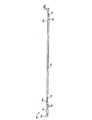
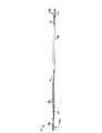
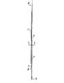
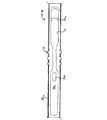
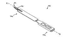
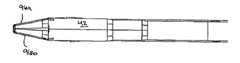
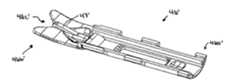
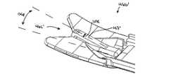
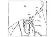
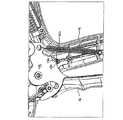
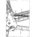
図1Aは、1つの例示的な外科クリップアプライヤ10を示している。図示されているように、クリップアプライヤ10は、固定ハンドル14を有するハウジング12、およびハウジング12に旋回可能に結合されている可動ハンドルすなわちトリガー16を含む。細長いシャフト18が、ハウジング12から延びている。この細長いシャフト18は、その遠位端部に、外科クリップを圧縮形成するための一対の対向した顎部を備えている。細長いシャフト18は、ハウジング12に回転可能に結合することができ、ハウジング12に対してシャフト18を回転させるための回転つまみ22を含むことができる。図1Bは、図1Aに示されている外科クリップアプライヤ10の組立分解図であり、これらの様々な構成要素は、以降に詳細に説明する。 FIG. 1A shows one exemplary
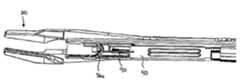
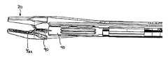
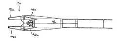
図2A−図12は、外科クリップアプライヤ10のシャフト18の様々な構成要素の例示的な実施形態を例示している。図1Bを参照されたい。一般に、シャフト18は、クリップトラック30およびプッシュロッド溝形部材32が形成された顎部保持シャフト28を有する顎部保持組立体26を含みうるシャフトの構成要素を受容する外管24を含む。顎部20は、クリップトラック30の遠位端部に結合するように構成することができる。シャフト組立体18は、クリップ前進組立体を含むこともできる。クリップ前進組立体は、一実施形態では、クリップトラック30内にスライド可能に受容され、かつ一連のクリップ36をこのクリップトラック30内を前進させるように構成されたフィーダーシュー34と、フィーダーシュー30をクリップトラック30内を移動させるように構成されたフィードバー38を含むことができる。フィードバー38は、フィードバー38の遠位端部に結合するように構成された、最遠位クリップを顎部20内に前進させるための前進組立体40を含むことができる。シャフト組立体18は、クリップ形成またはカム動作組立体を含むこともできる。このクリップ形成またはカム動作組立体は、例示的な一実施形態では、顎部20にスライド可能に結合するように構成されたカム42、およびカム42に結合してこのカム42を顎部20に対して移動させることができるプッシュロッド44を含むことができる。シャフト組立体は、クリップトラック30の遠位端部に結合できる、手術部位に対する顎部20の配置を容易にする組織ストッパー46を含むこともできる。 2A-12 illustrate exemplary embodiments of various components of the
1つの例示的なクリップ前進組立体の様々な構成要素が、図2A‐図5に詳細に示されている。まず、図2A‐図2Dを参照すると、顎部保持組立体26は、外管24に結合する近位端部28aおよび顎部20に結合するように構成された遠位端部28bを有する、実質的に平面の細長い顎部保持シャフト28を含む。様々な技術を用いて、顎部保持シャフト28の近位端部28aを外管24に結合することができるが、例示されている実施形態では、近位端部28aは、外管24に形成された対応する孔すなわち開口(不図示)内に受容されるように構成された、その近位端部28aの相反する両側に形成された歯31と、その近位端部28aに形成されたカットアウト29を含む。このカットアウト29により、近位端部28aの相反する両側が撓んでバネを形成することができる。具体的には、カットアウト29により、顎部保持シャフト28が外管24内に挿入されると、顎部保持組立体28の近位端部28aの相反する両側が互いに向かって圧縮される。歯31が、外管24の対応する開口に整合すると、顎部保持シャフト28の近位端部28aが、圧縮されていない元の構造に戻り、これにより、歯31が対応する開口内に進入して外管24に係合する。さらなる詳細は、図4Aを参照して後述するが、装置は、使用中に顎部保持組立体28の近位端部28aの相反する両側が圧縮されるのを防止して、歯31が外管24から偶発的に係合解除されるのを防止する機構を含むこともできる。 The various components of one exemplary clip advancement assembly are shown in detail in FIGS. 2A-5. Referring first to FIGS. 2A-2D, jaw retention assembly 26 has a
様々な技術を用いて、顎部保持シャフト28の遠位端部28bを顎部20に結合させることができるが、例示されている実施形態では、図7を参照して詳細を後述するように、顎部20に形成された対応する突出部すなわち歯94に係合する複数のカットアウトすなわち歯78が、顎部保持シャフト28の遠位端部28bに形成されている。これらの歯78により、顎部20の近位部分が、顎部保持シャフト28と実質的に同一平面になることができる。 Various techniques can be used to couple the distal end 28b of the
顎部保持組立体26には、プッシュロッド44をスライド可能に受容するためのプッシュロッド溝形部材32を設けることもできる。詳細を後述するように、プッシュロッド44を用いて、顎部20に対してカム42を前進させることができる。プッシュロッド溝形部材32は、様々な技術を用いて形成することができ、プッシュロッド44の形状および大きさによって任意の形状および大きさを有することができる。図2Dに示されているように、プッシュロッド溝形部材32は、例えば溶接によって保持シャフト28の上面に固着される。プッシュロッド溝形部材32はまた、実質的に矩形の形状を有し、内部に延びる通路32aを画定している。プッシュロッド溝形部材32は、保持シャフト28の全てまたは一部に沿って延在させることができる。当業者であれば、顎部保持組立体26は、外科クリップアプライヤ10の細長いシャフト18内でのプッシュロッド44の移動を容易にするために、プッシュロッド溝形部材32を必ずしも含まなくてもよいことを理解できよう。 The jaw holder assembly 26 may also be provided with a push
さらに図2A‐図2Dに示されているように、顎部保持組立体26は、この顎部組立体26に結合された、またはこの顎部組立体に形成されたクリップトラック30を含むこともできる。クリップトラック30は、図示されているように、顎部保持シャフト28の下面に結合され、クリップトラック30の遠位端部30bを顎部20に実質的に整合させることができるように、顎部保持シャフト28の遠位端部28bよりも遠位側まで延びている。クリップトラック30は、使用の際に、内部に少なくとも1つのクリップ、好ましくは複数のクリップを受容できるように構成されている。したがって、クリップトラック30は、クリップの両脚が互いに軸方向に整合するように、1または複数のクリップの対向した脚を内部に受容するように構成された、対向したサイドレール80aおよび80bを含むことができる。例示的な実施形態では、クリップトラック30は、製造の際に、その内部に約20個のクリップを事前に装着できるように構成することができる。当業者であれば、クリップトラック30の形状、大きさ、および構造は、クリップ、またはクリップトラック30内に受容されるように構成されたステープルなどの他の閉止装置の形状、大きさ、および構造によって様々に変更することができる。さらに、クリップトラック30の代わりに様々な他の技術を用いて、供給するクリップを細長いシャフト18に保持させることができる。 As further shown in FIGS. 2A-2D, the jaw holder assembly 26 may include a
クリップトラック30は、詳細を後述するように、その内部に配置されるように構成されたフィーダーシュー34に形成されたタング82aを受容するための複数の開口30cを備えることもできる。例示的な実施形態では、クリップトラック30は、装置10内に事前に配置されるように構成され、使用中に取り付けられるクリップの数と少なくとも同数の開口30cを含む。開口30cは、フィーダーシュー34が前進する度に、そのフィーダーシュー34のタング82aが開口30cに係合するように互いに等距離離間するのが好ましい。図示していないが、開口30cではなく凹部を含むことができる。または、クリップトラック30は、フィーダーシュー34に係合してそのフィーダーシュー34の遠位側への移動は防止するが、近位側への移動を可能にする他の構造を含むことができる。クリップトラック30は、図2Bに示されているストッパータング118を備えることができる。このストッパータング118は、フィーダーシュー34に形成された一致するストッパータングに係合して、詳細を後述するように、最遠位を越えてフィーダーシュー34が移動するのを防止することができる。ストッパータング118は、様々な構造を有することができるが、例示的な一実施形態では、クリップトラックの一部を取り囲むように互いに向かって延びた2つ近接したタブの形態であるため、クリップが通過することができる。 The
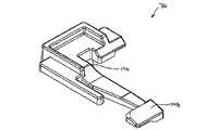
例示的なフィーダーシュー34は、図3Aおよび図3Bに詳細が示されているように、クリップを、クリップトラック30内を直接移送できるように構成することができる。フィーダーシュー34は、様々な構造を有することができるが、様々な他の技術を用いて、クリップを、クリップトラック30内を移動させることができる。例示的な実施形態では、フィーダーシュー34は、近位端部34aおよび遠位端部34bを備えた全体的に細長い形状を有する。遠位端部34bは、クリップトラック30内の最近位クリップを保持して、そのクリップをクリップトラック30内を押すように構成することができる。例示されている例示的な実施形態では、遠位端部34bは、クリップのV型の湾曲部分を受容するために実質的にV型である。遠位端部34bは、詳細を後述するように、アドバンサー(前進組立体)40が最遠位クリップに係合して、そのクリップを顎部20内を前進させることができるように、矩形ノッチ34cを備えることもできる。もちろん、遠位端部34bは、クリップ、または装置10とともに使用する他の閉止機構の構造によって様々に変更することができる。 The
別の例示的な実施形態では、フィーダーシュー34は、クリップトラック30内でのフィーダーシュー34の遠位側への移動を容易にするとともに、クリップトラック30内でのフィーダーシュー34の近位側への移動を実質的に防止する機構を含むこともできる。このような構造により、クリップトラック30内でのクリップの前進および適切な配置が確実になるため、詳細を後述するように、トリガー16の作動の度に、最遠位クリップが、顎部20間に前進することができる。例示されている例示的な実施形態では、フィーダーシュー34は、その上面34sに、クリップトラック30に形成された開口30cの1つに係合するための近位側に傾斜したタング82aが形成されている。使用の際、このタング82aの傾斜により、フィーダーシュー34がクリップトラック30内を遠位側にスライドすることができる。フィーダーシュー34が前進する度に、タング82aが、クリップトラック30のある開口30cから次の開口30cまで遠位方向に移動する。タング82aとクリップトラック30の開口30cとの係合により、詳細を後述するように、フィーダーシュー34が近位側に移動して元の位置に戻るのが防止されている。 In another exemplary embodiment, the
クリップトラック30内でのフィーダーシュー34の遠位側への移動を容易にするために、フィーダーシュー34は、フィードバー38が遠位側に移動するときにフィーダーシュー34がこのフィードバー38(図4A)に係合できるように、図3Bに示されているようにフィーダーシュー34の下面34iにタング82bを備えることもできる。この下側タング82bは、近位方向に傾斜できるという点で上側タング82aに類似している。使用の際、フィードバー38が遠位側に移動する度に、フィードバー38に形成された凹部84が、下側タング82bに係合して、フィーダーシュー34をクリップトラック30内を遠位側に所定距離移動させることができる。次いで、フィードバー38が、元の位置まで近位側に移動することができ、下側タング82bの傾斜角により、この下側タング82bが、フィードバー38に形成された次の凹部84内にスライドすることができる。上記したように、タング82a、82bおよび開口30cまたは凹部84以外の他の様々な構造を用いて、クリップトラック30内でのフィーダーシュー34の移動を制御することができる。 In order to facilitate movement of the
上記したように、フィーダーシュー34は、ストッパーを備えることもできる。このストッパーは、フィーダーシュー34が最遠位にあって装置10内にクリップが残っていない場合、フィーダーシュー34の移動を防止するように構成されている。ストッパーは様々な構造を有することができるが、図3Aおよび図3Bは、クリップトラック30に形成されたストッパータング118(図2B)に係合するために下方に延びた、フィーダーシュー34に形成された第3のタング82cを例示している。第3のタング82cは、フィーダーシュー34が最遠位にある場合にクリップトラック30のストッパータング118に係合して、供給するクリップがなくなった時にフィーダーシュー34およびフィードバー38の移動を防止するように配置されている。 As described above, the
図4Aは、フィーダーシュー34を、顎部保持組立体26のクリップトラック30内を移動させるための例示的なフィードバー38を例示している。図示されているように、フィードバー38は、近位端部38aおよび遠位端部38bを備えた全体的に細長い形状である。フィードバー38の近位端部38aは、詳細を後述するように、フィードバーカップラー50(図1B)に結合するように構成することができる。フィードバーカップラー50は、トリガー16の作動時にフィードバー38を細長いシャフト18内を遠位側にスライドさせるフィードリンク52に結合することができる。フィードバー38の遠位端部38bは、詳細を後述するように、クリップトラック30内に配置された最遠位クリップを顎部20内に移動させるアドバンサー40、40’(例示的な実施形態が図5Aおよび図5Bに示されている)に結合するように構成することができる。 FIG. 4A illustrates an
上記したように、フィードバー38の近位端部38aは、装置の使用中に、顎部保持シャフト28の近位端部28a(図2Aおよび図2B)の相反した両側が圧縮されるのを防止して、歯31が外管24から偶発的に外れるのを防止する機構を含むことができる。図4A‐図4Cに示されている例示的な一実施形態では、フィードバー38の近位端部38aは、顎部保持シャフト28の近位端部28aに形成された開口29内に延在するように構成された突出部39を備えることができる。フィードバー38が最近位(すなわち、トリガー16が開位置)にある場合、突出部39が、図4Bに示されているように、開口29の近位端部に位置し、顎部保持シャフト28の近位端部28aが圧縮されて、このシャフト28が外管24内にスライドすることができる。フィードバー38が最遠位(すなわち、トリガー16が少なくとも部分的に閉じた位置)にある場合、突出部39が、図4Cに示されているように、歯31に近接した中間位置に位置し、顎部保持シャフト28の近位端部28aが圧縮されるのが防止されている。これは、特に装置の使用中に有利である。なぜなら、突出部39が、装置の使用中に、顎部保持シャフト28が外管24から偶発的に外れるのを防止するためである。図4A‐図4Cは、縁が丸い矩形の断面である突出部39を例示しているが、突出部39は、様々な他の形状および大きさを有することができる。例えば、図4Dおよび図4Eに示されているように、突出部39’は、装置の使用中に顎部保持シャフト28の近位端部28aが圧縮されないように歯31間に延在できるように構成された、端部がテーパの三角形のような断面形状を有する。2つ以上の突出部を用いることもできる。例えば、図4F‐図4Hは、フィードバー38の近位端部38a’が、互いに所定距離離間した2つの突出部39aおよび39bを備えている別の実施形態を例示している。2つの突出部39aおよび39bは、フィードバー38が、図4Fに示されている最近位に位置する場合と、図4Hに示されている最遠位に位置する場合に顎部保持シャフト28が圧縮されるのを防止する。顎部保持シャフト28の近位端部28aの圧縮は、図4Gに示されているように、フィードバーが中間位置に位置して、歯31が突出部39aと39bとの間に位置する場合にのみ可能となる。 As noted above, the proximal end 38a of the
上記したように、フィードバー38は、フィーダーシュー34に形成された下側タング82bを受容するための1または複数の凹部84を備えることができる。凹部84の数は、様々に変更することができるが、例示的な実施形態では、フィードバー38は、装置10によって供給されるように構成されたクリップと同数またはそれ以上の凹部84を有する。より好ましくは、フィードバー38は、装置10によって供給されるように構成されたクリップの数よりも1つ多い凹部84を有する。限定するものではないが、一例として、フィードバー38は、クリップトラック30内に事前に配置された17個のクリップを供給するために、内部に18の凹部84を備えることができる。このような構成により、クリップを取り付けるために、フィードバー38が、フィーダーシュー34を17回前進させて17個のクリップを顎部20内に前進させることができる。凹部84は、フィードバー38が前進する度に、フィードバー38がフィーダーシュー34に係合してこのフィーダーシュー34を前進させるように、互いに等距離離間するのが好ましい。 As described above, the
フィードバー38は、クリップトラック30に対するフィードバー38の移動距離を制御する機構を含むこともできる。このような構造により、トリガー16が作動する度に、確実にフィーダーシュー34が所定距離前進し、これにより、唯1つのクリップが顎部20内に前進する。様々な技術を用いてフィードバー38の遠位側への移動を制御することができるが、例示的な実施形態では、フィードバー38は、顎部保持シャフト28に形成された対応するスロット88(図2B)内にスライド可能に受容されるように構成された突出部86を備えることができる。スロット88の長さは、その内部の突出部86の移動を制限して、フィードバー38の移動が制限することができる。したがって、使用の際、フィードバー38は、クリップトラック30に対して固定された近位と固定された遠位との間でスライドして、その前進の度に、フィーダーシュー34を所定距離前進させることができる。 The
図5Aは、フィードバー38の遠位端部38bに結合して、最遠位クリップをクリップトラック30から顎部20内に前進させるように構成されたアドバンサー40の例示的な一実施形態を例示している。様々な技術を用いて、アドバンサー40をフィードバー38に結合させることができるが、例示的な実施形態では、アドバンサー40の近位端部40aは、フィードバー38の遠位端部38bに形成された雄型コネクタを受容するように構成された雌型コネクタの形態である。アドバンサー40は、フィードバー38に結合するのが好ましいが、オプションとして、フィードバー38と一体形成することもできる。フィードバー38の遠位端部40bは、好ましくは、クリップを顎部20内に前進させるように構成され、アドバンサー40の遠位端部40bが、例えばクリッププッシャー部材90を備えることができる。クリッププッシャー部材90は、様々な形状および大きさを有することができるが、例示的な一実施形態では、クリップの湾曲部分を受容するための凹部92が、その遠位端部に形成された細長い形状を有する。凹部92の形状は、クリップの構造によって様々に変更することができる。クリッププッシャー部材90は、アドバンサー40の長軸Aに対して上方に、所定の角度で延びることもできる。このような構成により、クリッププッシャー部材90が、クリップトラック30内に進入してクリップに係合するとともに、アドバンサー40の残りの部分が、クリップトラック30に実質的に平行に延在することができる。図5Bは、アドバンサー40’のクリッププッシャー部材90’の別の例示的な実施形態を例示している。この実施形態では、クリッププッシャー部材90’は、やや細めであり、その最遠位端部に小さな凹部92’が形成されている。使用の際、アドバンサー40は、クリップトラック30内に配置された最遠位クリップのみに係合して、このクリップを顎部20内に前進させることができる。これは、上記したように、固定された近位と固定された遠位との間でスライド可能なフィードバー38の配置によって達成される。 FIG. 5A illustrates an exemplary embodiment of an advancer 40 configured to couple to the distal end 38 b of the
図6A‐図6Gは、使用中のクリップ前進組立体を例示している。具体的には、図6A‐図6Dは、フィーダーシュー34および一連のクリップ36を前進させるクリップトラック30内でのフィードバー38の動きを例示し、図6Eおよび図6Fは、最遠位クリップを顎部20内に移動させるアドバンサー40の動きを例示している。クリップ前進組立体を作動させるために用いるハウジング12内の構成要素を、以下に詳細に説明する。 6A-6G illustrate the clip advancement assembly in use. Specifically, FIGS. 6A-6D illustrate the movement of the
図6Aに示されているように、静止状態では、フィードバー38は最近位に位置し、突出部86が、顎部保持シャフト28の細長いスロット88内の近位側に位置している。フィーダーシュー34は、クリップトラック30内に配置され、装置10がまだ使用されていないとすると、フィーダーシュー34が最近位に位置し、フィーダーシュー34の上側タング82aが、クリップトラック30に形成された最近位すなわち第1の開口30c1に係合して、フィーダーシュー34の近位側への移動が防止されており、フィーダーシュー34の下側タング82bが、フィードバー38の第1の凹部841と第2の凹部842との間に位置し、下側タング82bが、フィードバー38によって上方に付勢されている。フィードバーの各凹部84は、順に841、842などとし、クリップトラック30の開口30cは、順に30c1、30c2などとした。図6Aに示されているように、36Xが最遠位クリップとなるように順に361、362、・・・36Xとして一連のクリップ36が、クリップトラック30内でフィーダーシュー34の遠位側に配置されている。As shown in FIG. 6A, in the resting state, the
トリガー16が作動すると、フィードバー38が遠位側に前進して、突出部86がスロット88内を遠位側にスライドする。フィードバー38が遠位側に移動すると、フィーダーシュー34の下側タング82bが、フィードバー38の第1の凹部841内にスライドする。フィードバー38がさらに遠位側に移動すると、図6Bに示されているように、第1の凹部841が下側タング82bに係合して、フィーダーシュー34および一連のクリップ361、362などが遠位方向に移動する。図6Cに示されているように、突出部86が顎部保持シャフト28の細長いスロット88の遠位端部に当接すると、フィードバー38が、さらに遠位側に移動するのが防止される。この位置では、フィーダーシュー34が所定距離前進して、供給されるクリップ361、362、・・・36Xが、クリップトラック30内を所定距離前進する。フィーダーシュー34の上側タング82aは、クリップトラック30の第2の開口30c2内に前進して、フィーダーシュー34の近位側への移動を防止し、フィーダーシュー34の下側タング82bは、フィードバー38の第1の凹部841に係合したままである。When the
フィードバー38が、図6Aに示されている初めの最近位から、図6Cに示されている最後の最遠位に移動すると、最遠位クリップ36Xが顎部20内に前進する。具体的には、図6Eに示されているように、フィードバー38の遠位側への移動により、フィードバー38の遠位端部に取り付けられたアドバンサー40のクリッププッシャー部材90が、クリップトラック30内に配置された最遠位クリップ36Xに係合して、図6Fに示されているように、この最遠位クリップ36Xを顎部20内に前進させる。例示的な実施形態では、フィーダーシュー34が係合して前進を開始する前に、アドバンサー40は、最遠位クリップ36Xに係合して、この最遠位クリップ36Xを前進させる。この結果、最遠位クリップ36Xは、フィーダーシュー34が移動する距離よりも長い距離前進する。このような構成により、別のクリップが偶発的に顎部20内に前進することなく、最遠位クリップ36Xのみが顎部20内に前進することができる。As the
クリップ36Xが、部分的または完全に形成されたら、トリガー16を解放して形成されたクリップ36Xを解放することができる。トリガー16の解放により、図6Dに示されているように、突出部86が細長いスロット88内の初めの最近位に戻るまで、フィードバー38もまた近位方向に引き戻される。フィードバー38が近位側に引き戻されても、上側タング82aがクリップトラック30の第2の開口30c2に係合するため、フィーダーシュー34は近位側に引き戻されない。下側タング82bは、フィードバー38の近位側への移動を妨げないため、図示されているように、フィードバー38が初めの最近位に戻ると、下側タング82が、フィードバー38の第2の凹部842と第3の凹部843との間に配置される。Clip 36X is, when partially or fully formed, it is possible to release the clips 36X formed by releasing the
この動作を繰り返して、別のクリップを顎部20内に前進させることができる。トリガー16の各作動で、下側タング82bが、フィードバー38に形成された次の凹部すなわち凹部842に係合し、フィーダーシュー34の上側タング82aが、遠位側に移動してクリップトラック30の次の開口すなわち開口30c3内に進入し、最遠位クリップが顎部20内に前進し、そして解放される。装置10が、例えば17個の所定数のクリップを含む場合、トリガー16を17回作動させることができる。最終クリップが取り付けられたら、例えばフィーダーシュー34の第3のタング82cであるストッパーが、クリップトラック30のストッパータング118に係合して、フィーダーシュー34のさらなる遠位側への移動を防止することができる。This action can be repeated to advance another clip into the
フィーダーシュー34、フィードバー38、および/またはクリップトラック30は、例えば装置の輸送中に、フィーダーシュー34の偶発的すなわち意図しない移動を防止するための機構をオプションとして含むこともできる。これは、特に装置を最初に使用する前のフィーダーシュー34の移動で装置が故障するような時に、特に有利である。例えば、フィーダーシュー34が遠位側に移動した場合、フィーダーシュー34が、2つのクリップを顎部内に同時に前進させて、2つの形成不良のクリップが供給されることになる。したがって、例示的な実施形態では、フィーダーシュー34、フィードバー38、および/またはクリップトラック30は、係合機構を含むことができ、および/またはこれらの間に摩擦力を発生させるように構成することができる。このような摩擦力は、移動を阻止するのに十分であるが、トリガー16の作動が打ち勝って、フィードバーがフィーダーシュー34をクリップトラック30内を前進させることができる大きさである。 The
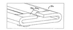
様々な技術を用いて、クリップトラック30内でのフィーダーシュー34の不所望の移動を防止することができるが、図27A‐図29Cは、フィーダーシュー34、フィードバー38、および/またはクリップトラック30との間に摩擦すなわち係合機構を形成するための技術の様々な実施形態を例示している。まず、図27Aを参照すると、クリップトラック30内に配置されると、フィーダーシュー34’がカンチレバーバネを形成するように、自由な状態(すなわち、フィーダーシュー34’がクリップトラック30から取り外された状態)で予備形成されたカンチレバー構造すなわち曲げ構造を有するフィーダーシュー34’の例示的な一実施形態が示されている。具体的には、フィーダーシュー34’の一部は、フィーダーシュー34’の両端部34a’と34b’が互いに対して角度をなすように、曲げ部35’を含むことができる。曲げ部35’により、フィーダーシュー34’の高さhbが、クリップトラック30の高さよりも高くなる。この高さhbは、様々に変更することができるが、例示的な実施形態では、曲げ部35’は、トリガー16が作動したときにフィーダーシュー34’がクリップトラック30内をスライドできる程度の摩擦抵抗力をフィーダーシュー34’とクリップトラック30との間に発生させるのに十分な程度にフィーダーシュー34’の高さhbを増大するように構成することができる。例示的な実施形態では、フィーダーシュー34’の高さは、少なくとも約30%、より好ましくは約40%増大される。使用の際、フィーダーシュー34’がクリップトラック30内に配置されると、クリップトラック30は、そのフィーダーシュー34’を実質的に平面構造にし、フィーダーシュー34’がクリップトラック30によって押圧される。つまり、フィーダーシュー34’の曲げ部35’およびフィーダーシュー34’の両端部34a’および34b’が、クリップトラック30に対して力を加えるため、フィーダーシュー34’とクリップトラック30との間に摩擦抵抗力を発生させる。この摩擦抵抗力により、トリガー16が作動しない限り、フィーダーシュー34’がクリップトラック30に対して移動するのが防止される。トリガー16が作動する場合は、トリガー16によって加えられる力が、この摩擦抵抗力に打ち勝つ。Although various techniques can be used to prevent undesired movement of the
当業者であれば、曲げ部35’は、様々な構造を有することができ、フィーダーシュー34’の長さに沿って任意の位置に形成できることを理解できよう。図27Aでは、曲げ部35’は、フィーダーシュー34’の中間部分またはその近傍に形成されている。曲げ部35’は、様々な方向にも延びることができる。図27Aは、曲げ部35’および両端部34a’、34b’がクリップトラック30に力を加えるように、長軸に対して垂直な方向に延在する曲げ部35’を例示しているが、別法として、曲げ部35’は、フィーダーシュー34’が、クリップトラック30の対向したサイドレール80aおよび80b(図2D)に力を加えるように、フィーダーシュー34’の長軸に沿って延在することもできる。曲げ部35’は、図27Aに示されているように、フィーダーシュー34’が実質的にA型となるように対向した両端部34a’と34b’が下方に所定の角度をなすようにしてもよいし、図27Bに示されているように、フィーダーシュー34’’が実質的にV型となるように、対向した両端部34a’’と34b’’が上方に所定の角度をなすようにしてもよい。フィーダーシュー34’は、任意の数の曲げ部を形成することもできる。当業者であれば、曲げ部の構造を、フィーダーシュー34’およびクリップトラック30の特性に基づいて変更して、フィーダーシュー34’とクリップトラック30の間に所望の摩擦力を得ることができることを理解できよう。 One skilled in the art will appreciate that the bend 35 'can have a variety of structures and can be formed at any location along the length of the feeder shoe 34'. In FIG. 27A, the bent portion 35 'is formed at or near the middle portion of the feeder shoe 34'. The bend 35 'can extend in various directions. FIG. 27A illustrates a
図28Aおよび図28Bは、フィーダーシューとクリップトラックとの間に摩擦力を発生させるための技術の別の実施形態を例示している。この実施形態では、クリップトラック30’および/またはフィーダーシュー34xに、1または複数の表面突起を形成することができる。図28Aに示されているように、2つの表面突起82d1、82d2が、クリップトラック30’に形成されている。表面突起82d1、82d2は、クリップトラック30’の全長に沿った位置または対向したサイドレールの内側などのクリップトラック30’の様々な位置、またはフィーダーシュー34Xの様々な位置に形成することができるが、例示されている実施形態では、2つの表面突起82d1、82d2は、クリップトラック30’の近位端部に近接して形成され、使用する前、例えば輸送の際のフィーダーシューの初めの移動を防止するように配置されている。2つの表面突起82d1、82d2の大きさは、フィーダーシュー34Xの不所望の移動を防止するのに必要な摩擦力の大きさによって様々に変更することができる。28A and 28B illustrate another embodiment of a technique for generating a frictional force between a feeder shoe and a clip track. In this embodiment, the clip track 30 'and / or the
表面突起82d1、82d2は、フィーダーシュー34Xの不所望の移動を防止するのに十分な摩擦力を発生させるように構成することができるが、フィーダーシュー34Xおよび/またはクリップトラック30’は、オプションとして、対応する表面突起に係合するように構成された構造を含むこともできる。図28Bは、クリップトラック30’の表面突起82d1、82d2に係合する、フィーダーシュー34Xの遠位部分に形成された対向したタング82e1および82e2を例示している。これらのタング82e1および82e2は、様々な構造にすることができ、表面突起82d1、82d2に係合するか、または表面突起82d1、82d2を捕捉するように構成されたリップまたは他の突出部を含むことができる。図28Bに示されているように、タング82e1および82e2は、フィーダーシュー34’の対向したサイドレールから互いに向かって延びている。Surface protrusions 82d1, 82d2, which can be configured to generate a sufficient frictional force to prevent movement
図29A‐図29Cは、フィーダーシューの不所望の移動を防止するための技術の別の実施形態を例示している。この実施形態では、フィーダーシューとフィードバーとの間に摩擦を発生させる。具体的には、フィーダーシュー34yは、図29Aに示されているように、リップ82gが形成されたタング82fを含み、フィードバー38yは、図29Bに示されているように、一致する溝84yが形成されている。図29Cに示されているように、リップ82gは、使用の際に、溝84yに係合してフィーダーシュー34yの不所望の移動を防止するように構成されている。しかしながら、リップ82gおよび溝84yは、トリガー16の作動によってフィーダーシュー34yに十分な力がかかると、フィーダーシュー34yが移動できるように構成されている。29A-29C illustrate another embodiment of a technique for preventing undesired movement of the feeder shoe. In this embodiment, friction is generated between the feeder shoe and the feed bar. Specifically, the
当業者であれば、様々な他の技術を用いて、クリップトラック内でのフィーダーシューまたは他のリップ前進機構の不所望の移動を防止することができ、任意の機構の組合せを用い、一方または両方の構成要素の様々な位置に配置できることを理解できよう。 A person skilled in the art can use various other techniques to prevent undesired movement of the feeder shoe or other lip advancement mechanism within the clip track, using any combination of mechanisms, either or It will be appreciated that both components can be placed in various locations.
図7‐図9は、クリップ形成組立体の様々な例示的な構成要素を例示している。まず図7を参照すると、顎部20の例示的な実施形態が示されている。上記したように、顎部20は、顎部保持シャフト28に形成された対応する歯78に結合するための歯94を有する近位部分20aを含むことができる。しかしながら、他の技術を用いて、顎部20を顎部保持シャフト28に結合することができる。例えば、あり結合(dovetail connection)および嵌め込み結合(male-female connection)などを用いることができる。別法として、顎部20は、保持シャフト28と一体形成することができる。顎部20の遠位部分20bは、これらの顎部の間にクリップを受容するように構成することができる。したがって、遠位部分20bは、互いに対して移動可能な対向した第1の顎部材96aおよび第2の顎部材96bを含むことができる。例示的な実施形態では、顎部材96aおよび96bは、開位置に付勢されており、これらの顎部材96aおよび96bを互いに向かって移動させるためには力が必要である。各顎部材96aおよび96bは、クリップの脚をこれらの顎部材に整合して受容するために、これらの顎部材の対向した内面に溝(溝97のみを図示)を備えることができる。各顎部材96aおよび96bは、カム42がこれらの顎部材96aおよび96bに係合して、これらの顎部材96aおよび96bを互いに向かって移動させることができるように、カムトラック98aおよび98bを備えることもできる。例示的な実施形態では、カムトラック98aおよび98bは、顎部材96aおよび96bは、顎部材96aおよび96bの上面に形成されている。 7-9 illustrate various exemplary components of the clip forming assembly. Referring first to FIG. 7, an exemplary embodiment of
図8は、顎部材96aおよび96bにスライドして結合して、これらの顎部材96aおよび96bを係合させるための例示的なカム42を例示している。カム42は、様々な構造を有することができるが、この例示的な実施形態では、詳細を後述するように、プッシュロッド44に結合するように構成された近位端部42a、および顎部材96aおよび96bに係合するように構成された遠位端部42bを含む。様々な技術を用いて、カム42をプッシュロッド44に結合させることができるが、この例示されている例示的な実施形態では、カム42に、プッシュロッド44の遠位端部44bに形成された雄型部材すなわちキー部材102を受容するように構成された雌型すなわちキー型カットアウト100が形成されている。雄型部材102は、プッシュロッド44を例示している図9に詳細に示されている。図示されているように、雄型部材102は、2つの部材42、44が結合できるようにカットアウト100に一致する形状を有する。当業者であれば、カム42とプッシュロッド44は、オプションとして、互いに一体形成できることを理解できよう。プッシュロッド44の近位端部44aは、プッシュロッド44とカム42が顎部20に対して移動できるように、詳細を後述するように、閉止リンク組立体に結合するように構成することができる。 FIG. 8 illustrates an
さらに図8に示されているように、カム42は、顎部20に形成された細長いスロット20c内にスライド可能に受容されるように構成された突出部42cを備えることもできる。突出部42cとスロット20cは、使用の際に、クリップ形成組立体の近位ストッパーとなるように機能することができる。 As further shown in FIG. 8, the
再び図8を参照されたい。カム42の遠位端部42bは、顎部材96aおよび96bに係合するように構成することができる。様々な技術を用いることができるが、例示されている例示的な実施形態では、遠位端部42は、顎部材96aおよび96bのカムトラック98aおよび98bをスライド可能に受容するためのカム動作溝すなわちテーパ凹部104を備えている。図10Aおよび図10Bに示されているように、カム42は、使用の際に、顎部材96aおよび96bが互いに対して所定距離離間する近位から、顎部材96aおよび96bが互いに近接する近位まで前進することができる。カム42が顎部材96aおよび96bに対して前進すると、テーパ凹部104により、顎部材96aおよび96bが互いに向かって移動し、これらの間に配置されたクリップが圧縮形成される。 Please refer to FIG. 8 again. The distal end 42b of the
上記したように、外科クリップアプライヤ10は、手術部位の組織を顎部20内に配置しやすくする組織ストッパー46を含むこともできる。図11Aは、近位端部46aおよび遠位端部46bを備えた組織ストッパー46の例示的な一実施形態を示している。近位端部46aは、組織ストッパー46を顎部20に近接して配置するために、クリップトラック30の遠位端部に結合するように構成することができる。しかしながら、組織ストッパー46は、クリップトラック30と一体形成してもよいし、またはシャフト18の様々な他の構成要素に結合するように構成するか、またはこれらの構成要素と一体形成してもよい。組織ストッパー46の遠位端部46bは、標的部位に対して顎部20を配置および整合するために、これらの間に血管、管、シャントを配置するように構成された形状を有することができる。図11Aに示されているように、組織ストッパー46の遠位端部46bは、実質的にV型である。遠位端部46bは、トロカールまたは他のアクセスチューブを介した装置の配置を容易にする湾曲構造を有することもできる。 As noted above, the
組織ストッパーまたは装置の他の構成要素は、オプションとして、クリップ形成の際にクリップを支持して安定させるための機構を含むこともできる。クリップが顎部間で形成される際に、クリップが旋回して形成不良が起きることがある。具体的には、顎部が閉じる時に、クリップの各脚の端部が互いに向かって移動する。この結果、顎部が、各脚の曲げ部分にのみ係合するため、脚の端部およびクリップの頂部の顎部との整合がずれて、顎部に対して垂直方向に旋回することがある。したがって、顎部がさらに閉じると、形成不良のクリップが形成される。したがって、装置は、クリップを顎部内に整合させて誘導し、クリップの形成の際にクリップが旋回したり、他の原因で整合がずれるのを防止する機構を含むことができる。 The tissue stopper or other component of the device may optionally include a mechanism for supporting and stabilizing the clip during clip formation. When the clip is formed between the jaws, the clip may turn to cause poor formation. Specifically, when the jaws close, the ends of each leg of the clip move toward each other. As a result, the jaw part engages only with the bent part of each leg, so that the end part of the leg and the jaw part at the top of the clip are misaligned, and the jaw part may pivot in a direction perpendicular to the jaw part. . Therefore, when the jaw is further closed, a poorly formed clip is formed. Thus, the device can include a mechanism that guides the clip into alignment within the jaw and prevents the clip from pivoting or otherwise misaligned during clip formation.
このような整合機構は、様々な構成を有することができ、装置の様々な構成要素に形成することができるが、図11Aは、クリップとアドバンサー組立体40の遠位端部との整合を維持するために、組織ストッパー46の遠位端部46bの中間部分に形成された中心タング47を例示している。具体的には、中心タング47により、クリップの頂部がその中心タング47に沿って移動するため、クリップを遠位方向に押しているアドバンサー組立体40に対してクリップがずれるのを防止することができる。当業者であれば、組織ストッパー46は、様々な他の構成を有することができ、構造に沿ったクリップの前進を容易にする様々な他の構造を含むことができることを理解できよう。 While such an alignment mechanism can have a variety of configurations and can be formed on various components of the device, FIG. 11A provides alignment between the clip and the distal end of the
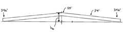
図11B‐図11Dは、整合機構すなわちガイド部材が形成された組織ストッパー46’の別の例示的な実施形態を例示している。この整合機構は、クリップを顎部内に整合させて誘導するように構成され、より好ましくは、クリップの形成の際にクリップを顎部に整合した状態に維持するように構成されている。この実施形態では、整合機構は、組織ストッパー46’の中心軸に沿って長手方向に延び、この組織ストッパー46’の上面から延出しているランプ部材47’の形態である。このランプ部材47’は、好ましくは硬質であり、組織ストッパー46’の近位端部46a’から遠位端部46b’にかけて高さが増大している。しかしながら、この傾斜角は、顎部の角度によって様々にすることができる。ランプ部材47’は、組織ストッパー46’の遠位端部に形成された組織受容凹部46c’のすぐ近位側まで延在するのが好ましい。この結果、ランプ部材47’が、顎部20のすぐ近位側に位置するため、ランプ部材47’が、クリップおよびクリップを押すアドバンサー組立体40のチップを適切な角度で顎部20内に誘導することができる。ランプ部材47’は、使用の際に、顎部20間に配置されたクリップの頂部の下面に当接して、顎部20が閉じてクリップを形成する際のクリップの垂直方向の旋回を防止することができる。具体的には、アドバンサー組立体40が、ランプ部材47’に沿って最遠位に移動すると、クリップの頂部がランプ部材47’の上面に当接する。クリップが顎部20間で圧縮されてクリップの脚が互いに向かって移動すると、顎部20は、各脚の曲げ部分のみに係合する。この結果、クリップの脚および頂部が垂直方向に自由に旋回することができる。しかしながら、クリップの頂部がランプ部材47’の上面47a’に支持されるため、ランプ部材47’が頂部の垂直下方への移動を防止し、これにより、クリップの脚が垂直上方に移動するのが防止される。すなわち、ランプ部材47’が、クリップが顎部20内でずれるのを防止する。したがって、ランプ部材47’は、顎部20が閉じてクリップを形成する際に生じる有害な回転力を防止または制限することができる。したがって、クリップの顎部20内での整合が維持される。 11B-11D illustrate another exemplary embodiment of a tissue stopper 46 'formed with an alignment mechanism or guide member. The alignment mechanism is configured to guide and align the clip within the jaw, and more preferably configured to maintain the clip aligned with the jaw during formation of the clip. In this embodiment, the alignment mechanism is in the form of a ramp member 47 'that extends longitudinally along the central axis of the tissue stopper 46' and extends from the top surface of the tissue stopper 46 '. The ramp member 47 'is preferably rigid and increases in height from the proximal end 46a' to the
当業者であれば、ランプ部材の形状、大きさ、および構造は、顎部およびクリップアプライヤの他の構成要素の特有の構造によって様々に変更できることを理解できよう。例示的な一実施形態では、ランプ部材47’は、約0.635mm(約0.025in)の最大高さhRmax(組織ストッパー46’を通る中心平面から測定)を有することができる。より好ましくは、この最大高さhRmaxは、約0.203mm〜0.508mm(約0.008in〜約0.020in)の範囲であり、最も好ましくは約0.254mm〜0.381mm(約0.010in〜約0.015in)の範囲である。ランプ部材47’の傾斜角αRも同様に様々に変更することができるが、例示的な実施形態では、ランプ部材47’は約5度〜45度、より好ましくは5度〜30度、最も好ましくは10度〜20度の範囲の傾斜角αRを有する。ランプ部材47’の幅wrも同様に様々に変更することができるが、例示的な実施形態では、ランプ部材47’は、完全に閉じた位置にある顎部20間の空間よりもわずかに狭い幅wrを有するのが好ましい。One skilled in the art will appreciate that the shape, size, and structure of the ramp member can vary depending on the specific structure of the jaws and other components of the clip applier. In one exemplary embodiment, the
図12は、使用中の組織ストッパー46を例示している。図示されているように、組織ストッパー46は、顎部20の近位側に位置しているため、顎部20間に血管、管、シャントなどを受容することができる。図示されているように、外科クリップ36は、顎部20間に配置され、その湾曲部分36aが組織ストッパー46に整合している。このため、クリップ36の脚36bが、血管、管、シャント、または他の標的部位の周りに完全に配置することができる。 FIG. 12 illustrates the
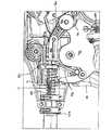
図13‐図26Bは、クリップの前進と形成を制御するための、ハウジング12の様々な例示的な内部構成要素を例示している。上記したように、外科クリップアプライヤ10は、ここに開示する一部または全ての機構を含むことができ、当分野で周知の他の様々な機構を含むことができる。ある例示的な実施形態では、クリップアプライヤ10の内部構成要素として、少なくとも1つのクリップを細長いシャフト18内を前進させて、このクリップを顎部20間に配置するための、シャフト18に結合するクリップ前進組立体と、顎部20を閉じて部分的または完全に閉じたクリップを形成するための、シャフト18に結合するクリップ形成組立体を含むことができる。他の例示的な機構には、トリガー16の動きを制御するためのバックアップ防止機構、クリップ形成組立体によって顎部20に加えられる過度の力を防止するための過負荷防止機構、および装置10に残っているクリップの数を表示するためのクリップ数表示機構が含まれる。 FIGS. 13-26B illustrate various exemplary internal components of the
図13‐図16Dは、シャフト18内でフィードバー38を移動させるための、ハウジング12内のクリップ前進組立体の例示的な実施形態を例示している。一般に、クリップ前進機構は、トリガー16に結合されたトリガーインサート48と、フィードバー38の近位端部38aに結合できるフィードバーカップラー50と、トリガーインサート48からフィードバーカップラー50に運動を伝達するための、トリガーインサート48とフィードバーカップラー50との間に延びるように構成されたフィードリンク52を含むことができる。 FIGS. 13-16D illustrate an exemplary embodiment of a clip advancement assembly within the
図14は、トリガーインサート48の詳細を例示している。トリガーインサート48の形状は、ハウジング12の他の構成要素によって様々に変更することができるが、例示的な実施形態では、トリガーインサート48は、ハウジング12に旋回可能に結合するように構成された中心部分48a、トリガー16内に延びてそのトリガー16に結合するように構成された細長い部分48bを含む。中心部分48aは、トリガーインサート48をハウジング12に旋回可能に結合するためのシャフトを受容する貫通孔106を含むことができる。中心部分48aは、フィードリンク52の一部を受容するための第1の凹部108を、その上面に形成することもできる。第1の凹部108は、トリガー16の移動によりトリガーインサート48が旋回する際にフィードリンク52が強制的に旋回されるように、フィードリンク52の一部を受容できる大きさおよび形状を有するのが好ましい。図14に示されているように、第1の凹部108は、実質的に細長く、図16を参照して詳細を説明するように、フィードリンク52の近位端部に形成されたシャフトを受容するために実質的に円形の部分を含む。トリガーインサート48は、カム42を作動させて顎部20を閉じるためにプッシュバー44に結合された閉止リンクローラ54を受容するための、後面に形成された第2の凹部110と、詳細を後述するように、トリガー16の移動を制御するために爪60に結合する、底面に形成されたラチェット歯112を含むこともできる。 FIG. 14 illustrates details of the
例示的なフィードバーカップラー50が、図15Aおよび図15Bに詳細が示されている。フィードバーカップラー50は、フィードバー38の近位端部をフィードリンク52の遠位端部に結合するように構成することができる。様々な技術を用いてフィードバーカップラー50をフィードバー38の近位端部38aに結合することができるが、例示的な実施形態では、フィードバーカップラー50は、2つの別個の半体50aおよび50bから形成されている。これらの半体50aおよび50bは、互いに結合され、これらの間にフィードバー38の近位端部38aを保持する。結合されると、2つの半体50aおよび50bは、中心シャフト50cを画定する。この中心シャフト50cは、その両端部に形成された実質的に円形のフランジ50dおよび50eを備え、これらの円形フランジ50dと50eの間にフィードリンク52の遠位部分を受容するための凹部50fが画定されている。中心シャフト50cは、フィードバー38の近位部分38aを受容するとともに、フィードバー38をフィードカップラー58に対して実質的に固定位置にロックするための貫通孔50gを画定している。しかしながら、フィードバーカップラー50は、フィードバー38と一体に形成してもよいし、フィードリンク52との結合を容易にする様々な他の形状および大きさにしてもよい。 An exemplary
図16は、トリガーインサート48とフィードバーカップラー52との間に延在することができる例示的なフィードリンク52を例示している。一般に、フィードリンク52は、近位端部52aおよび遠位端部52bを備えた概ね平面の細長い形状を有することができる。近位端部52aは、上記したように、トリガーインサート48の第1の凹部108内に回転可能に受容されるように構成されており、貫通するシャフト53(図1B)を含むことができる。このシャフト53は、トリガーインサート48の第1の凹部108内で旋回するよう回転できるように構成することができ、これにより、トリガーインサート48がフィードリンク52を旋回させることができる。フィードリンク52の遠位端部52bは、フィードバーカップラー50に結合するように構成することができる。したがって、例示的な一実施形態では、フィードリンク52の遠位端部52bに、対向したアーム114aおよび114bを形成することができる。これらのアーム114aおよび114bの間には、フィードバーカップラー50の中心シャフト50aを受容する開口116が画定されている。アーム114aおよび114bは、カップラー50に係合し、フィードリンク52が旋回軸Xを中心に旋回する際に、このカップラー50を移動させることができる。旋回軸Xは、フィードリンク52がハウジング12に結合する位置によって画定され、フィードリンク52の任意の位置に配置することができる。しかしながら、この例示的な実施形態では、旋回軸Xは、フィードリンク52の近位端部52aに近接している。 FIG. 16 illustrates an
例示的な実施形態では、フィードリンク52は、クリップ前進組立体およびクリップ形成組立体を較正する必要がないように可撓性にすることができる。具体的には、フィードリンク52は、たとえフィードバー38およびフィードバーカップラー50が最遠位に移動しても、閉じた位置に向かうトリガー16のさらなる移動を可能にし、クリップ形成組立体およびクリップ前進組立体にある程度の自由を付与する。言い換えれば、トリガー16が、その閉止の際にフィードバー38に対して柔軟である。 In the exemplary embodiment, feed
フィードリンク52の剛性および強度は、クリップ前進組立体およびクリップ形成組立体の構造によって様々にすることができるが、例示的な一実施形態では、フィードリンク52は、517kPa〜758kPa(75lbs/in〜110lbs/in)の剛性、より好ましくは約641kPa(約93lbs/in)(リンク52とフィードカップラー50との間の接触面で測定)の剛性を有し、172kPa〜345kPa(25lbs〜50lbs)の強度、より好ましくは約241kPa(約35lbs)の強度を有する。フィードリンク52はまた、様々なポリマーおよび金属を含む様々な材料から形成することができる。1つの例示的な材料は、ガラス強化ポリエーテルイミドであるが、ガラス強化液晶ポリマー、ガラス強化ナイロン、およびこれらの炭素繊維強化型、並びに同様の熱プラスチックを含む様々な強化熱プラスチックを用いることができる。熱硬化ポリエステルなどの繊維強化熱硬化ポリマーも用いることができる。フィードリンク52は、限定された可撓性と制御された強度の所望の組合せを得るために、バネ鋼などの金属から形成することもできる。 While the stiffness and strength of the
図17A‐図17Dは、使用中の例示的なクリップ前進組立体を例示している。図17Aは、トリガー16が開位置で静止し、フィードバーカップラー50およびフィードバー38が最近位にあり、フィードリンク52がトリガーインサート48とフィードバーカップラー50との間に延在している初期位置を示している。上記したように、初めの開位置では、フィードバー38の突出部86が、顎部保持シャフト28の細長いスロット88の近位端部に位置する。例えばバネ120である第1の付勢部材が、トリガーインサート48およびハウジング12に結合して、トリガーインサート48およびトリガー16を開位置に維持しており、例えばバネ122である第2の付勢部材が、シャフト18をハウジング12に回転可能に結合するシャフトカップラー124とフィードバーカップラー50との間に延在して、このフィードバーカップラー50およびフィードバー38を最近位に維持している。 17A-17D illustrate an exemplary clip advancement assembly in use. FIG. 17A shows an initial position where the
トリガー16が、作動され、バネ120および122による付勢力に打ち勝って閉止位置すなわち固定ハンドル14に向かって移動すると、図17Bに示されているように、トリガーインサート48が反時計回りの方向に旋回し始める。この結果、フィードリンク52が、半時計の周りの方向に強制的に旋回され、これにより、フィードバーカップラー50およびフィードバー38が遠位方向に移動する。したがって、フィードバー38の突出部86が、顎部保持シャフト28の細長いスロット88内を遠位側に移動し、これにより、クリップトラック内に配置されたフィーダーシュー34およびクリップ36が前進する。バネ120は、ハウジングとトリガーインサート48との間で伸張し、バネ122は、フィードバーカップラー50とシャフトカップラー124との間で圧縮されている。 When the
トリガー16がさらに作動され、トリガーインサート48がさらに旋回すると、フィードバーカップラー50およびフィードバー38が最終的に最遠位に到達する。この位置では、フィードバー38の突出部86が、顎部保持シャフト28のスロット88の遠位端部に位置し、上記したように、クリップが顎部20間に配置されている。バネ122は、図17Cおよび図17Dに示されているように、シャフトカップラー124とフィードバーカップラー50との間で完全に圧縮され、フィードリンク52が湾曲している。フィードリンク52が湾曲し、より好ましくはフィードリンク52が完全に湾曲すると、クリップ形成組立体が作動して顎部20を閉じる。フィードリンク52が、例えば作動の第2の段階であるクリップ形成組立体の作動の際に湾曲したまま維持されるため、トリガーインサート48は、クリップ前進組立体、特にフィードバー38に対して柔軟である。 As the
ハウジング12の例示的なクリップ形成組立体が、図18‐図20に詳細に示されている。一般に、クリップ形成組立体は、ハウジング12内に配置され、プッシュロッド44およびカム42を顎部20に対して移動させて顎部20を閉止位置に移動させ、これにより、顎部20間に配置されたクリップを圧縮形成する。クリップ形成組立体は、様々な構造を有することができるが、例示されている実施形態では、トリガーインサート48にスライド可能に結合された閉止リンクローラ54、この閉止リンクローラ54に結合するように構成された閉止リンク56、およびこの閉止リンク56およびプッシュロッド44に結合するように構成された閉止カップラー58を含む。 An exemplary clip forming assembly of
図18は、閉止リンクローラ54を詳細に例示している。図示されているように、この閉止リンクローラ54は、中心シャフト54aを含む。この中心シャフト54aは、その相反する両端部に近接して形成された実質的に円形のフランジ54bおよび54cを備えている。中心シャフト54aは、フランジ54bおよび54cがトリガーインサート48の相反する側面を受容するように、トリガーインサート48の第2の凹部110内に配置されるように構成することができる。中心シャフト54aはまた、対向したアーム126aおよび126bに結合して、閉止リンク56の対向したアーム126aおよび126bをトリガーインサート48の相反する側面に配置するように構成することができる。 FIG. 18 illustrates the
閉止リンク56の例示的な実施形態が、図19に詳細に示されている。図示されているように、閉止リンク56は、互いに所定距離離間した対向したアーム126aおよび126bを有する。各アーム126aおよび126bは、閉止リンクローラ54の中心シャフト54aに結合するように構成された近位端部128aおよび128bと、閉止リンクローラ54と閉止リンク56をプッシュロッド44に結合するために、閉止カップラー58に結合するように構成された遠位端部130aおよび130bを含む。例示的な実施形態では、各アーム126aおよび126bの近位端部128aおよび128bは、閉止リンクローラ54に旋回可能に係合するように構成されており、これにより、アーム126aおよび126bは、例えば、中心シャフト54aに係合するフック型部材132aおよび132bを備えることができる。これらのフック型部材132aおよび132bは、閉止リンク56と閉止リンクローラ54との間の係合を容易にするために反対方向に延びている。アーム126aおよび126bの遠位端部130aおよび130bは、互いに結合することができ、閉止リンク56を閉止カップラー58に旋回可能に結合するように構成されているシャフトを受容するための貫通孔134を含むことができる。当業者であれば、様々な他の技術を用いて、閉止リンク56を閉止リンクローラ54および閉止カップラー58に結合できることを理解できよう。 An exemplary embodiment of the
例示的な閉止カップラー58が、図20Aに詳細に示されている。図示されているように、閉止カップラー58は、貫通孔138aおよび138bが形成された2つのアーム136aおよび136bを備えた近位部分58aを含む。これらの貫通孔138aおよび138bは、閉止カップラー58と閉止リンク56を結合するためのシャフトを受容するべく、閉止リンク56の貫通孔134に整合するように構成されている。閉止カップラー58はまた、プッシュロッド44の近位端部44a(図9)に結合するように構成された遠位部分58bを含むことができる。例示的な実施形態では、閉止カップラー58に、プッシュロッド44の近位端部44aを受容する形状を有するカットアウト59(図20Bおよび図20C)が形成されている。閉止カップラー58の遠位部分58bは、トリガー16が開位置にある場合に、フィードバーカップラー50の一部を受容するように構成することもできる。当業者であれば、様々な他の結合技術を用いて、閉止カップラー58をプッシュロッド44に結合することができ、オプションとして、閉止カップラー58とプッシュロッド44を互いに一体形成できることを理解できよう。 An
他の例示的な実施形態では、特に閉止の初期段階で、使用者がトリガー16を緩めた場合に、クリップが顎部から偶発的に落下するのを防止するために、予荷重接合部を、プッシュロッド44と閉止カップラー58との間に設けることができる。具体的には、詳細を後述するバックアップ防止機構は、トリガー16が所定の位置に達するまでトリガー16が開かないように構成することができるが、トリガー16のわずかな移動を可能にすることもできる。したがって、使用者がトリガー16を緩めてトリガー16がわずかに開いた際に、予荷重接合部が、プッシュロッド44を遠位方向に押し、これにより、プッシュロッド44が実質的に固定位置に維持されるとともに、閉止カップラー58が、トリガー16がバックアップ防止機構に係合するまで近位側に移動することができる。 In other exemplary embodiments, preload joints may be used to prevent the clip from accidentally dropping from the jaws, particularly when the user loosens the
予荷重接合部は、様々な構造を有することができ、クリップ形成組立体に沿った様々な位置に配置することができるが、例示的な一実施形態では、予荷重接合部は、カットアウト59内に配置された、プッシュロッド44を遠位方向に付勢する付勢部材の形態にすることができる。様々な付勢部材を用いることができるが、図20Bに示されている実施形態では、付勢部材は、プッシュロッド44の近位端部44aと凹部59の後壁との間に配置された、プッシュロッド44を遠位側に付勢するカンチレバービーム61である。このカンチレバービーム61は、近位方向の力が加えられると、曲がって平坦になることができるニチノールなどの形状記憶材料から形成することができる。ビーム61はまた、バネ鋼または強化ポリマーなどの様々な他の材料から形成することができ、2つ以上のビームを用いることもできる。図20Cは、コイルまたは他のタイプのバネ63の形態である付勢部材の別の実施形態を例示している。図示されているように、バネ63は、プッシュロッド44を遠位側に付勢するためにプッシュロッド44の近位端部44aと凹部59の後壁との間に配置されている。バネ63は、近位方向の力が加えられると、収縮するように構成されている。当業者であれば、弾性圧縮部材などの様々な他の付勢部材を用いることができることを理解できよう。 Although the preload joint can have a variety of structures and can be placed at various locations along the clip forming assembly, in one exemplary embodiment, the preload joint is cut out 59. It may be in the form of a biasing member disposed therein that biases the
予荷重接合部はまた、オプションとして、クリップ形成工程の際にカンチレバービームまたはバネの性能を改善する機構を含むこともできる。図20Bに示されている実施形態では、カンチレバービーム61の荷重は、閉止の際にカンチレバービーム61が圧縮される時に、主として均一に維持されるが、この荷重は、閉止の最終段階で著しく増大する。これは、図20Dに例示されている。図20Dは、図20Bに示されているカンチレバービーム61の荷重/変位曲線のグラフを示している。曲線の左端部は、荷重がかかっていないカンチレバービーム61の高さを示し、曲線の右端部は、カンチレバービーム61が完全に収縮すなわち平坦になった点を示している。上側の曲線は、一般的な閉止ストロークの際にカンチレバービーム61が圧縮される時に生じる力を示している。ただし、この力は、カンチレバービーム61に負荷がかかっていない状態から測定したものであり、カンチレバービーム61は、閉止カップラー58内に配置されると初めに部分的に圧縮される。図示されているように、荷重は、初期の圧縮段階を除き、実質的に一定に維持され、カンチレバービーム61が圧縮される閉止ストロークの際にわずかに増大するだけである。しかしながら、荷重は、カンチレバービーム61が完全に平坦になる閉止の最終段階で急激に増大する。これは、カンチレバービーム61の変位により、カンチレバービーム61の両端部から内側に向かって荷重が伝達されることによる。カンチレバービーム61が変位して荷重が内側に伝達されると、カンチレバービーム61の有効長さが短くなって荷重が増大する。これを防止するために、予荷重接合部は、オプションとして、特にクリップ形成の際に荷重を実質的に一定に維持する、カンチレバービームまたはバネの性能を向上させる機構を含むことができる。 The preload joint may also optionally include a mechanism that improves the performance of the cantilever beam or spring during the clip forming process. In the embodiment shown in FIG. 20B, the load of the cantilever beam 61 is maintained primarily uniform when the cantilever beam 61 is compressed during closure, but this load increases significantly during the final stage of closure. To do. This is illustrated in FIG. 20D. FIG. 20D shows a graph of the load / displacement curve of the cantilever beam 61 shown in FIG. 20B. The left end of the curve shows the height of the unloaded cantilever beam 61, and the right end of the curve shows the point at which the cantilever beam 61 is completely contracted or flattened. The upper curve shows the force that occurs when the cantilever beam 61 is compressed during a typical closing stroke. However, this force is measured from a state where no load is applied to the cantilever beam 61, and the cantilever beam 61 is initially partially compressed when placed in the closing
図20Eはカンチレバービームまたはバネの性能を改善するための技術の例示的な一実施形態を例示している。図示されているように、閉止カップラー58’の凹部59’は、その後面に2つのリッジ59a’および59b’が形成されており、これらのリッジ59a’および59b’は、カンチレバービーム(不図示)の下側すなわち後側に位置する。リッジ59a’および59b’は、互いに所定距離離間している。各リッジ59a’および59b’は、カンチレバービーム61が凹部の後面に接触して完全に平坦にならないように、少なくとも約0.127mm(約0.005in)の高さを有する。この結果、リッジ59a’および59b’が、カンチレバービーム61が変位するのを防止し、これにより、バネすなわちカンチレバービームの荷重が、その両端部から内側に向かって伝達されるのが防止される。当業者であれば、リッジ59a’および59b’の特定の位置、数、および大きさは、予荷重接合部の構造と、閉止の際にクリップが落下するのを防止するために必要な力によって様々に変更できることを理解できよう。 FIG. 20E illustrates one exemplary embodiment of a technique for improving the performance of a cantilever beam or spring. As shown, the recess 59 'of the closing coupler 58' has two
再び図17A‐図17Bを参照されたい。使用の際、トリガー16が、初めに開位置から閉止位置に向かって移動すると、閉止リンクローラ54が、トリガーインサート48の凹部110内で回転する。図17Cに示されているように、フィードバー38およびフィードバーカップラー50が最遠位に達すると、トリガー16のさらなる作動により、図17Dに示されているように、トリガーインサート48の凹部110が閉止リンクローラ54に係合して、この閉止リンクローラ54をトリガーインサート48とともに旋回させる。この結果、閉止カップラー58が遠位側に移動し、これによりプッシュロッド44が遠位側に移動する。プッシュロッド44が遠位側に前進すると、カム42が顎部20に対して前進して、顎部20を閉止し、顎部間に配置されたクリップが圧縮形成される。トリガー16は、オプションとして、部分的に閉止して顎部20を部分的に閉止し、これにより、顎部間の配置されたクリップを部分的に圧縮形成することができる。クリップの選択的な完全閉止および部分閉止を容易にするための例示的な技術を詳細に後述する。クリップが取り付けられたら、トリガー16を解放することができる。トリガー16が解放されると、バネ120が、トリガーインサート48をその初期位置に引き戻すことができ、バネ122が、フィードバーカップラー50およびフィードバー38を近位に押し戻すことができる。トリガーインサート48が初期位置に戻ると、閉止リンクローラ54もその初期位置に戻るため、閉止リンク56、閉止カップラー58、およびプッシュバー44が近位側に引き戻される。 Refer again to FIGS. 17A-17B. In use, when the
外科クリップアプライヤ10は、この装置10の使用を容易にする様々な他の機構を含むこともできる。例示的な一実施形態では、外科クリップアプライヤ10は、トリガー16の動きを制御するためのバックアップ防止機構を含むことができる。具体的には、このバックアップ防止機構は、部分的な閉止ストロークの際にトリガー16が開くのを防止することができる。しかしながら、トリガーが、顎部間に配置されたクリップを部分的に圧縮形成できる所定の位置に達したら、バックアップ防止機構がトリガーを解放することができ、使用者の選択によって、トリガーを開いてクリップを解放するか、またはトリガーを閉じてクリップを完全に圧縮形成することができる。
図21Aおよび図21Bは、ラチェットの形態のバックアップ防止機構の例示的な一実施形態を例示している。図示されているように、このラチェットは、トリガーインサート48に形成された一連の歯112と、ハウジング12内に回転可能に配置されるように構成された爪60を含む。この爪60は、トリガー16の閉止およびトリガーインサート48の旋回により歯112に係合するように、トリガーインサート48に近接して配置されている。歯112は、爪60が、自由に回転してトリガー16を開閉できる所定の位置に達するまで、爪60の回転を防止するように構成することができる。この所定の位置は、顎部20が部分的に閉じる位置に一致するのが好ましい。例示的な実施形態では、図示されているように、歯112は、例えば10の歯からなる第1の一連の歯112aを含む。この第1の一連の歯112aは、爪60に係合すると、この第1の一連の歯112aに対する爪60の回転を防止して、トリガー16が開くのを防止する大きさを有する。歯112は、タック歯(tock tooth)112bと呼ぶ最後の歯を含むこともできる。このタック歯112bは、爪60に係合すると、爪60が、このタック歯112bに対して回転できる大きさを有する。具体的には、タック歯112bは、第1の一連の歯112aとタック歯112bとの間に比較的大きなノッチ140が形成されるように、第1の一連の歯112aの大きさよりもかなり大きくするのが好ましい。ノッチ140は、その内部で爪60が旋回できて、爪60が、選択的にタック歯112bを越えて移動するか、または第1の一連のハウジング112aに向かって戻ることができる大きさを有する。当業者であれば、タック歯112bは、第1の一連の歯112aとの間に形成されるノッチ140内で爪60の旋回が可能であれば、第1の一連の歯112aと同じまたはそれ以下の大きさを有することができることを理解できよう。 21A and 21B illustrate one exemplary embodiment of a backup prevention mechanism in the form of a ratchet. As shown, the ratchet includes a series of
図22A‐図22Dは、使用中のラチェット機構を例示している。図22Aに示されているように、トリガー16が初めに閉止位置に向かって移動すると、爪60が、第1の一連の歯112aに係合してトリガー16が開くのを防止する。トリガー16がさらに作動すると、爪60は、第1の一連の歯112aを越えて、タック歯112bに隣接したノッチ140に達する。爪60がタック歯112bに達して、カム42の顎部20に対する部分的な遠位側への移動によって顎部20が部分的に閉じると、爪60が自由に回転できるため、使用者の選択によって、トリガー16を開くか、または閉じることができる。図22Cは、完全に閉じた位置にあるトリガー16を例示し、図22Dおよび図22Eは、開位置に戻っているトリガー16を例示している。 22A-22D illustrate the ratchet mechanism in use. As shown in FIG. 22A, when the
ラチェット機構は、顎部20の位置を表す可聴音を発するようにも構成することができる。例えば、爪60が第1の一連の歯112aに係合すると第1の音を発し、爪60がタック歯112bに係合すると、例えば第1の音よりも大きい第2の音を発するようにすることができる。この結果、トリガー16が、爪60がタック歯112bに係合する所定の位置に達すると、顎部20が部分的に閉じた位置にあることを、使用者が音で確認できる。したがって、使用者は、トリガー16を解放して部分的に閉じたクリップを解放するか、またはトリガー16を完全に閉じてクリップを完全に閉じることができる。 The ratchet mechanism can also be configured to emit an audible sound that represents the position of the
別の例示的な実施形態では、外科クリックアプライヤ10は、トリガー16によって顎部20に加えられる過剰な力を防止するように構成された過負荷防止機構を含むことができる。一般に、外科クリップの取付けの際に、顎部20を閉じて、その顎部20の間に配置された組織の周りのクリップを圧縮形成するために一定の力が必要である。形成工程が進んで、クリップが少なくとも部分的に閉じられると、クリップの周りの顎部20をさらに閉じるために必要な力は、著しく増大する。したがって、例示的な実施形態では、過負荷防止機構は、顎部20を閉じるために必要な力に相関する抵抗を有することができる。言い換えれば、過負荷防止機構の抵抗は、顎部20を閉じるために必要な力が増大すると、増大することができる。しかしながら、この抵抗は、過負荷防止機構の偶発的な作動を防止するために、顎部20を閉じるために必要な力よりもわずかに大きいのが好ましい。この結果、トリガー16が初めに作動した時に、顎部20が閉じられるのが防止される場合、過負荷防止機構の抵抗に打ち勝つために必要な力は比較的小さい。これは、顎部20が開いているまたは部分的に閉じている時に変形しやすいため、特に有利である。過負荷防止機構は、顎部の変形を防止するために、クリップ形成の早い段階では容易に作動する。逆に、顎部20が実質的に閉じている場合、顎部20に著しい力が加わった場合のみに過負荷防止機構が作動するように、抵抗が比較的大きい。 In another exemplary embodiment,
図23Aは、過負荷防止機構62の例示的な実施形態の組立分解図である。一般に、過負荷防止機構は、2つの半体64aおよび64bから形成された過負荷防止ハウジング64を含むことができる。過負荷防止ハウジング64は、プロフィールリンク66、トグルリンク68、ピボットリンク70、および付勢組立体72を含むことができる。付勢組立体72は、ハウジング64に結合されるバネポスト150を含むことができる。このバネポスト150は、プランジャー154を受容するための貫通孔を有する。バネ152は、バネポスト150の周りに配置され、プランジャー154は、バネポスト150内に導入され、バネ152に当接するように構成された頭部154aが形成されている。ピボットリンク70は、概ねL型とすることができ、貫通するピボットピン156によってハウジング64に結合することができる。ピボットリンク70の近位端部70aは、プランジャー154の頭部150aに接触することができ、ピボットリンク70の遠位端部70bは、ピボットピン166によってトグルリンク68に旋回可能に結合することができる。トグルリンク68は、ハウジング64に形成された開口64dに近接して、そのハウジング内にスライドおよび旋回可能に配置することができるプロフィールリンク66に結合することができる。ハウジング64内でのプロフィールリンク66の旋回は、例えば、プロフィールリンク66を貫通して、ハウジング64の各半体64aおよび64bに形成された第1のスロット160a(一方のスロットのみを図示)内に配置されるピボットピン158によって達成することができ、ハウジング64内でのプロフィールリンク66のスライドは、例えば、ハウジング64の各半体64aおよび64bに形成された第2のスロット160b(一方のスロットのみを図示)内に受容されるプロフィールリンク66に形成された、相反した突出部168aおよび168bによって達成することができる。 FIG. 23A is an exploded view of an exemplary embodiment of overload prevention mechanism 62. In general, the overload prevention mechanism can include an
プロフィールリンク66は、使用の際に、クリップ形成組立体からの力を受け取って、付勢組立体72の抵抗でその力に対抗するように構成することができる。具体的には、過負荷防止機構62は、トグルリンク68およびピボットリンク70とともにバネ152を用いて、プロフィールリンク66のピボットピン158を中心とする回転またはハウジング64に対する移動に対抗している。回転の点について述べると、圧縮されたバネ152によって生じる力が、トグルリンク68およびピボットリンク70を介して伝達され、ハウジング64に対してプロフィールリンク66に回転が加えられる。したがって、この組立体により、プロフィールリンク66は、ハウジング64に対する回転に抵抗する。プロフィールリンク66に対する閉止リンクローラ54からの径方向の荷重によって生成されるモーメントが、ピボットリンク70およびトグルリンク68のモーメントを超えると、プロフィールリンク66が回転し始め、トグルリンク68が座屈し、ピボットリンク70がバネ152をさらに圧縮する。スライドの点について述べると、ピボットリンク70、トグルリンク68、およびプロフィールリンク66は、スライドの力(スライドに対する抵抗)が、トグルリンク68およびピボットリンク70を座屈させるのに必要な力となるように整合されている。プロフィールリンク66に対する閉止リンクローラ54からの径方向の荷重が、リンケージの座屈の力を超えると、プロフィールリンク66が近位側にスライドして、ピボットリンク70がバネ152をさらに圧縮する。 The profile link 66 can be configured to receive a force from the clip forming assembly in use and counter the force with the resistance of the biasing
この詳細は、図23Bおよび図23Cに示されている。図示されているように、ハウジング64の開口64dにより、クリップ形成組立体の閉止リンクローラ54がプロフィールリンク66に対して転がることができる。この結果、トリガー16が作動して閉止位置に向かって移動する時に、閉止リンクローラ54がプロフィールリンク66に力を加える。しかしながら、閉止リンクローラ54によって加えられる力が、例えば閾値の力である抵抗よりも大きい力まで増大しない限り、過負荷防止バネ152の抵抗が、プロフィールリンク66を実質的に固定位置に維持する。これは、例えば、顎部20の間に異物がはさまった場合、または顎部20が、これらの間に血管、管、シャントなどが配置された状態でクリップを完全に閉じる場合に生じる。顎部20をさらに閉じることができない場合、トリガー16の閉止によって閉止リンクローラ54に加えられる力が、プロフィールリンク66に伝達され、この力により、プロフィールリンク66がハウジング64内で旋回およびスライドし、これによりピボットリンク70が旋回してプランジャー154を押し、過負荷防止バネ152が圧縮される。 This detail is shown in FIGS. 23B and 23C. As shown, the
上記したように、過負荷防止機構を作動させるために必要な力は、トリガー60が閉止位置に移動するにつれて増大する顎部20を閉じるために必要な力に相関させることができる。これは、プロフィールリンク66の構造によって達成できる。具体的には、図23Bに示されているように、閉止リンクローラ54がプロフィールリンク66に初めに接触して下側の位置にする場合、プロフィールリンク66が、ハウジング64内を旋回することができる。図23Cに示されているように、閉止リンクローラ54がプロフィールリンク66に沿って上方に移動すると、プロフィールリンク66をハウジング内64内でスライドさせなければならないため、過負荷防止機構の抵抗に打ち勝つために必要な力が増大する。プロフィールリンク66を旋回させるために必要な力は、プロフィールリンク66をスライドさせるために必要な力よりも小さくすることができる。したがって、トリガーが初めに作動した時に、例えば異物によって顎部20が閉じるのが妨げられた場合、閉止リンクローラ54がプロフィールリンク66の下側部分に力を伝達してプロフィールリンク66を旋回させるためには、わずかな力が必要なだけである。顎部20が実質的に閉じてトリガー16がほぼ完全に作動した場合、過負荷防止バネ152の抵抗に打ち勝って、閉止リンクローラ54がプロフィールリンク66の上部に力を伝達してプロフィールリンク66をハウジング64内でスライドさせるためには、相当な力が必要である。過負荷防止機構を作動させるために必要な力の大きさは、顎部20を閉じるために必要な力よりも大きくすることができ、かつその力の大きさに比例して増大させることができるが、この力は、顎部20の変形または他の損傷を防止するために、顎部20を閉じるために必要な力よりもわずかに大きくするのが好ましい。当業者であれば、この抵抗を、顎部20を閉じるために必要な力に基づいて調節できることを理解できよう。 As described above, the force required to operate the overload prevention mechanism can be correlated to the force required to close the
プロフィールリンク66、特にこのプロフィールリンク66の遠位側に面した表面66sは、過負荷防止機構を作動させるために必要な力と顎部20を閉じるために必要な力との間の相関性を容易にする形状を有することもできる。例えば、顎部20を閉めるために必要な力が線形に増大する場合は、プロフィールリンク66の遠位側に面した表面66sを平面にして、プロフィールリンク66に対する閉止リンクローラ54の動きにプロフィールリンク66が干渉されないようにし、線形の力をトリガー16に加えて顎部20を閉じることができる。逆に、トリガー16が閉止位置に移動する時に、顎部20を閉じるために必要な力が線形でない場合は、プロフィールリンク66は、非線形の力に一致する非線形の形状を有することができる。このような構造により、カム42(図8)を閉じるために必要な力が高くなりすぎるのが防止される。 The profile link 66, particularly the surface 66s facing the distal side of the profile link 66, provides a correlation between the force required to activate the overload protection mechanism and the force required to close the
限定目的ではない一例では、顎部20を閉じるために必要な力は、顎部材96aと96bを互いに押して近づけるように構成されたカム42の凹部104の形状によって非線形にすることができる。図8に示されているように、凹部104は、カム42が顎部材96aおよび96bを通過する時に力が変化するように湾曲構造を有することができる。したがって、プロフィールリンク66は、閉止リンクローラ54が遠位側に面した表面を通過する時にも力が変化するように、一致した湾曲した遠位側に面した表面を有することができる。図23Aおよび図23Bに示されているように、プロフィールリンク66は、その下部が実質的に凸状で、その上部が実質的に凹状に湾曲している。当業者であれば、プロフィールリンク66は、様々な他の形状を有することができ、そして様々な他の技術を用いて、顎部20を閉じるために必要な力と過負荷防止機構を作動させるために必要な力を最適にできることを理解できよう。 In one non-limiting example, the force required to close the
また、当業者であれば、過負荷防止機構が様々な他の構造を有することができることも理解できよう。限定目的ではない一例として、図23Dは、閉止リンクローラ54によって加えられる力を受け取るためのカンチレバービーム170の形態である過負荷防止機構を例示している。カンチレバービーム170は、一端にブラケット174が結合された、実質的に湾曲した部材172を有することができる。この湾曲した部材172は、曲げモーメントを有することができる。この曲げモーメントは、この曲げモーメントよりも大きい力がかかると、座屈して剛性が低い状態になる。ブラケット174は、曲げモーメントがブラケット174の近傍で増大するように、湾曲部材172に剛性を付与することができる。ビーム170は、使用の際に、そのくぼんだ面(concave surface)に閉止リンクローラ54が接触するように、クリップアプライヤ10のハウジング12内に設けることができる。ビーム170は、トリガー16が初めに作動した時に閉止リンクローラ54がそのビーム170から離れる方向に移動し、トリガー16が閉止位置に移動する時に、閉止リンクローラ54がそのビーム170に近づくようにある角度で配置することができる。この結果、閉止リンクローラ54が移動して、クリップアプライヤのトリガー16が閉止位置に移動する時に、座屈に対する抵抗が増大する。図示していないが、オプションとして、複数のビームを重ねて用いることができ、ビームの端部すなわち自由端を、そのビームの長さに沿った特定の点で座屈荷重に合う形状にすることができる。 Those skilled in the art will also appreciate that the overload prevention mechanism can have a variety of other structures. By way of example and not limitation, FIG. 23D illustrates an overload prevention mechanism in the form of a
別の例示的な実施形態では、外科クリップアプライヤ10は、装置10に残っているクリップの数を示すためのクリップ数表示機構を含むことができる。様々な技術を用いて残っているクリップの数を示すことができるが、図24A‐図25は、表示ホイール74および表示アクチュエータ76を有するクリップ数表示機構の例示的な一実施形態を例示している。 In another exemplary embodiment, the
表示ホイール74は、図24Aおよび図24Bに詳細に示されている。図示されているように、表示ホイール74は、このホイールが回転するように構成された中心軸Yを画定する全体的に円形または円筒状の形状を有する。ホイール74は、その周囲に形成された、表示アクチュエータ76が係合するように構成された歯142、および表示部材144を有する。この表示部材144は、様々な構造を有することができるが、例示的な実施形態では、表示ホイール74の他の部分とは異なるオレンジや赤などの色が付いた対比色パッドの形態である。 The
図25は、例示的な表示アクチュエータ76を詳細に例示している。このアクチュエータ76は、ハウジング12内にスライド可能に配置され、フィードバーカップラー50に結合して、フィードバーカップラー50およびフィードバー38が移動する時に移動するように構成されている。したがって、表示アクチュエータ76は、フィードバーカップラー50の円形フランジ50dと50eとの間に形成された凹部50f内に延びるために、表示アクチュエータ76の内面に形成された突出部146(一部のみを図示)を含むことができる。この突出部146により、表示アクチュエータ76は、フィードバーカップラー50に結合して、このフィードバーカップラー50とともに移動することができる。表示アクチュエータ76は、表示ホイール74に形成された歯142に係合するように構成された係合機構148を備えることもできる。図25に示されているように、表示アクチュエータ76の係合機構148は、歯142に係合するためのタブが端部に形成されたアームの形態である。 FIG. 25 illustrates an exemplary display actuator 76 in detail. The actuator 76 is slidably disposed within the
使用の際、表示ホイール74は、図26Aおよび図26Bに示されているように、ハウジング12内に回転可能に配置されて、表示アクチュエータ76は、係合機構148が表示ホイール74に近接し、突出部146がフィードバーカップラー50内に延びるようにハウジング12内にスライド可能に配置されている。ハウジング12は、表示部材144を視認するための窓12aを備えている。トリガー16が閉止位置に移動し、フィードバーカップラー50が遠位側に移動すると、表示アクチュエータ76が、フィードバー38およびフィードバーカップラー50とともに遠位側に移動する。この結果、表示アクチュエータ76の上の係合機構148が、表示ホイール74の歯142に係合し、これにより、クリップが顎部20内を前進する時に表示ホイール74が回転する。トリガー16が作動してクリップ20が顎部20内に前進する度に、表示アクチュエータ76により、表示ホイール74が回転する。供給できるクリップが2個または3個になると、表示ホイール74の対比色パッド144が、ハウジング12に形成された窓12aに出現し始め、2、3個のクリップしか残っていないことを使用者に示す。対比色パッド144は、供給できるクリップがなくなると、窓12a全体を占有するように構成することができる。 In use, the
別の例示的な実施形態では、表示ホイール74は、一旦前進すると、逆方向、例えば反時計回りの方向に回転するのを防止するように構成されたバックアップ防止機構を含むことができる。このバックアップ防止機構は、様々な構造を有することができるが、図24Bに例示されている実施形態では、表示ホイール74は、Y軸に実質的に平行に延びる対向したアーム73aおよび73bを含む。各アーム73aおよび73bは、ハウジング12に形成された対応する歯に係合するように構成された爪75aおよび75bをその遠位端部に備えている。図示されていないが、これらの対応する歯は、窓12aに近接したハウジング12の内部に形成された円形突出部内に形成することができる。表示ホイール74がハウジング12内に配置されると、アーム73aおよび73bが、ハウジングの内部に形成された円形突出部内に延びる。クリップが取り付けられて表示ホイール74が回転すると、アーム73aおよび73bは、ハウジング内の歯に対して撓んで次の位置に移動することができる。表示アクチュエータ76が近位側にスライドして元の位置に戻ると、アーム73aおよび73bがハウジング内の歯に係合して、表示ホイール74が逆方向に回転して元の位置に戻るのを防止する。当業者であれば、様々な他の技術を用いて、表示ホイール74の逆回転を防止できることを理解できよう。 In another exemplary embodiment, the
上記したように、外科クリップアプライヤ10を用いて、血管、管、シャントなどの手術部位にクリップを部分的または完全に閉じた状態に取り付けることができる。腹腔鏡および内視鏡外科手術では、患者の体に小さな切開部を形成して手術部位にアクセスする。通常はカニューレまたはアクセスポートを用いて、皮膚の切開部から手術部位まで延びる処置用の通路を画定する。外科手術の際に、血管または他の管を流れる血液を止める必要がある場合が多く、一部の処置では、シャントを使用する必要もある。したがって、外科クリップを用いて血管を閉じたり、シャントを血管に取り付けたりすることができる。したがって、クリップアプライヤ10などの外科クリップアプライヤを、カニューレを介してまたは他の方法で手術部位に導入し、血管、シャント、または他の管の周りに顎部20を配置することができる。組織ストッパー46は、標的部位の周りへの顎部20の配置を容易にすることができる。次いで、トリガー16を作動させ、クリップを顎部間に前進させて標的部位の周りに配置し、そして顎部20を閉じてクリップを圧縮形成させることができる。クリップの使用目的によって、トリガー16は、爪60がタック歯112bに到達する可聴音によって知らされる部分的な作動、または完全な作動を行うことができる。次いで、トリガー16を解放して、部分的または完全に閉じたクリップを解放する。さらにクリップを取り付ける必要があれば、この動作を繰り返すことができる。 As described above, the
当業者であれば、上記した実施形態に基づいて本発明の別の特徴および利点を理解できよう。したがって、本発明は、添付の特許請求の範囲を除き、上記説明および添付の図面に限定されるものではない。ここで言及した全ての刊行物および参照文献は、参照することをもってその開示内容を全て本明細書の一部とする。 One skilled in the art will appreciate further features and advantages of the invention based on the above-described embodiments. Accordingly, the invention is not limited to the above description and accompanying drawings, except as appended claims. All publications and references mentioned herein are hereby incorporated by reference in their entirety.
〔実施の態様〕
(1)互いに閉じてクリップすべき組織を近接させる顎部、これらの顎部を閉じるように構成されたプッシュロッド、このプッシュロッドを作動させるように構成されたトリガー、および閉止ストロークの少なくとも一部の際に前記トリガーが開くのを防止するように構成されたラチェット機構を有する、改善された内視鏡外科クリップアプライヤにおいて、
前記プッシュロッドとこのプッシュロッドを前記トリガーに結合するリンケージとの間に形成された予荷重接合部であって、閉止ストロークの際の前記トリガーが部分的に開いている時に、前記顎部を実質的に固定された部分的に閉じた位置に維持して、前記顎部間に部分的に形成されたクリップを保持する、予荷重接合部、
を含む、外科クリップアプライヤ。
(2)実施態様(1)に記載の外科クリップアプライヤにおいて、
前記予荷重接合部が、前記プッシュロッドを実質的に固定された位置に維持したまま、前記リンケージを近位側に移動させることができるように構成されている、外科クリップアプライヤ。
(3)実施態様(1)に記載の外科クリップアプライヤにおいて、
前記予荷重接合部が、閉止ストロークの際に前記プッシュロッドによって圧縮されるように構成された付勢部材を含み、この付勢部材が、前記トリガーが部分的に開いている時に、前記プッシュロッドに付勢力を加えるように構成されている、外科クリップアプライヤ。
(4)実施態様(3)に記載の外科クリップアプライヤにおいて、
前記付勢部材がカンチレバービームを含む、外科クリップアプライヤ。
(5)実施態様(3)に記載の外科クリップアプライヤにおいて、
前記付勢部材がバネを含む、外科クリップアプライヤ。Embodiment
(1) jaws that close each other and bring tissue to be clipped close together, a push rod configured to close these jaws, a trigger configured to actuate the push rod, and at least a portion of the closing stroke In an improved endoscopic surgical clip applier having a ratchet mechanism configured to prevent the trigger from opening during
A preload joint formed between the push rod and a linkage that couples the push rod to the trigger, wherein the jaw is substantially disengaged when the trigger is partially open during a closing stroke; A preload joint that maintains a partially formed clip between the jaws, maintaining a fixed, partially closed position
Including surgical clip applier.
(2) In the surgical clip applier according to the embodiment (1),
A surgical clip applier, wherein the preload joint is configured to allow the linkage to move proximally while maintaining the push rod in a substantially fixed position.
(3) In the surgical clip applier according to the embodiment (1),
The preload joint includes a biasing member configured to be compressed by the push rod during a closing stroke, and the biasing member is configured to push the push rod when the trigger is partially open. Surgical clip applier configured to apply a biasing force to the body.
(4) In the surgical clip applier according to the embodiment (3),
A surgical clip applier, wherein the biasing member includes a cantilever beam.
(5) In the surgical clip applier according to the embodiment (3),
A surgical clip applier, wherein the biasing member includes a spring.
(6)実施態様(3)に記載の外科クリップアプライヤにおいて、
前記プッシュロッドの近位端部および前記付勢部材が、結合機構に形成された凹部内に配置されており、前記バネが、前記プッシュロッドの前記近位端部を遠位側に付勢している、外科クリップアプライヤ。
(7)実施態様(6)に記載の外科クリップアプライヤにおいて、
前記凹部に、内部に少なくとも1つのリッジが形成されており、このリッジが、閉止ストロークの際の前記バネが圧縮されている時に、前記バネを実質的に一定の荷重に維持するように構成されている、外科クリップアプライヤ。
(8)実施態様(7)に記載の外科クリップアプライヤにおいて、
前記少なくとも1つのリッジが、前記バネが完全に圧縮されるのを防止するように構成されている、外科クリップアプライヤ。
(9)外科クリップアプライヤにおいて、
シャフトが延びているハンドルと、
前記シャフトの遠位端部に形成された顎部と、
前記シャフト内に延在し、前記顎部に結合された顎部閉止機構と、
前記顎部閉止機構を作動させて前記顎部を閉じるように構成されたトリガーと、
前記顎部閉止機構と前記トリガーとの間に形成された予荷重接合部であって、前記予荷重接合部が、閉止ストロークの際の前記トリガーが部分的に開いている時に、クリップが前記顎部から落下するのを防止するように構成されている、予荷重接合部と、
を含む、外科クリップアプライヤ。
(10)実施態様(9)に記載の外科クリップアプライヤにおいて、
前記予荷重接合部が、閉止ストロークの際に前記顎部閉止機構の一部によって圧縮されるように構成されたバネを含む、外科クリップアプライヤ。(6) In the surgical clip applier according to the embodiment (3),
The push rod proximal end and the biasing member are disposed in a recess formed in a coupling mechanism, and the spring biases the push rod proximal end distally. Surgical clip applier.
(7) In the surgical clip applier according to the embodiment (6),
The recess has at least one ridge formed therein, the ridge configured to maintain the spring at a substantially constant load when the spring is compressed during a closing stroke. Surgical clip applier.
(8) In the surgical clip applier according to the embodiment (7),
The surgical clip applier, wherein the at least one ridge is configured to prevent the spring from being fully compressed.
(9) In surgical clip applier,
A handle with a shaft extending;
A jaw formed at the distal end of the shaft;
A jaw closure mechanism extending into the shaft and coupled to the jaw;
A trigger configured to actuate the jaw closure mechanism to close the jaw;
A preload joint formed between the jaw closing mechanism and the trigger, wherein the preload joint is clipped when the trigger is partially open during a closing stroke; A preload joint configured to prevent falling from the part;
Including surgical clip applier.
(10) In the surgical clip applier according to the embodiment (9),
The surgical clip applier, wherein the preload joint includes a spring configured to be compressed by a portion of the jaw closure mechanism during a closure stroke.
(11)実施態様(10)に記載の外科クリップアプライヤにおいて、
前記バネがニチノールから形成されている、外科クリップアプライヤ。
(12)実施態様(9)に記載の外科クリップアプライヤにおいて、
前記顎部閉止機構が、前記顎部を閉じるように構成されたカム、そのカムに結合されたプッシュロッド、および前記プッシュロッドと前記トリガーとの間に延在する結合機構を含む、外科クリップアプライヤ。
(13)実施態様(12)に記載の外科クリップアプライヤにおいて、
前記予荷重接合部が、前記結合機構に形成された凹部内に配置され、閉止ストロークの際に前記プッシュロッドによって圧縮されるように構成されている、外科クリップアプライヤ。
(14)実施態様(13)に記載の外科クリップアプライヤにおいて、
前記凹部に、少なくとも1つのリッジが形成されており、この少なくとも1つのリッジが、閉止ストロークの際の前記予荷重接合部が圧縮される時に、前記予荷重接合部を実質的に一定の荷重に維持するように構成されている、外科クリップアプライヤ。
(15)実施態様(14)に記載の外科クリップアプライヤにおいて、
前記少なくとも1つのリッジが、前記バネが完全に圧縮されるのを防止するように構成されている、外科クリップアプライヤ。(11) In the surgical clip applier according to the embodiment (10),
A surgical clip applier, wherein the spring is formed from Nitinol.
(12) In the surgical clip applier according to the embodiment (9),
Surgical clip arm, wherein the jaw closure mechanism includes a cam configured to close the jaw, a push rod coupled to the cam, and a coupling mechanism extending between the push rod and the trigger. Pliers.
(13) In the surgical clip applier according to the embodiment (12),
The surgical clip applier, wherein the preload joint is disposed in a recess formed in the coupling mechanism and is configured to be compressed by the push rod during a closing stroke.
(14) In the surgical clip applier according to the embodiment (13),
At least one ridge is formed in the recess, and the at least one ridge causes the preload joint to have a substantially constant load when the preload joint is compressed during a closing stroke. A surgical clip applier configured to maintain.
(15) In the surgical clip applier according to the embodiment (14),
The surgical clip applier, wherein the at least one ridge is configured to prevent the spring from being fully compressed.
(16)外科クリップアプライヤにおいて、
ハウジングと、
そのハウジングから遠位側に延びたシャフトと、
前記シャフトの遠位端部に形成された第1および第2の顎部と、
前記ハウジングに移動可能に結合されたトリガーと、
少なくとも部分的な閉止ストロークの際に前記トリガーが解放されると、前記トリガーに係合するように構成されたバックアップ防止機構と、
前記トリガーと前記顎部との間に結合された組立体であって、少なくとも部分的な閉止ストロークの際に前記トリガーが解放されると、クリップが落下するのを防止するように前記顎部を実質的に固定された位置に維持するように構成されている、組立体と、
を含む、外科クリップアプライヤ。
(17)実施態様(16)に記載の外科クリップアプライヤにおいて、
前記組立体の一部を固定位置に維持するための予荷重接合部が、前記組立体内に形成されており、この予荷重接合部により、少なくとも部分的な閉止ストロークの際に前記トリガーが解放されると、前記組立体の一部が近位側に移動することができる、外科クリップアプライヤ。
(18)実施態様(17)に記載の外科クリップアプライヤにおいて、
前記予荷重接合部が、前記顎部に対してカムを前進させて前記顎部を閉じるように構成されたプッシュロッドと、このプッシュロッドを前記トリガーに結合するための結合機構との間に形成されており、前記予荷重接合部が、前記プッシュロッドを固定位置に維持し、少なくとも部分的な閉止ストロークの際に前記トリガーが解放されると、前記結合機構を近位側に移動させることができる、外科クリップアプライヤ。
(19)実施態様(18)に記載の外科クリップアプライヤにおいて、
前記予荷重接合部が、前記プッシュロッドと前記結合機構との間に配置されたバネを含む、外科クリップアプライヤ。(16) In a surgical clip applier,
A housing;
A shaft extending distally from the housing;
First and second jaws formed at the distal end of the shaft;
A trigger movably coupled to the housing;
A backup prevention mechanism configured to engage the trigger when the trigger is released during at least a partial closing stroke;
An assembly coupled between the trigger and the jaw, wherein the jaw is arranged to prevent the clip from falling when the trigger is released during at least a partial closing stroke. An assembly configured to maintain a substantially fixed position;
Including surgical clip applier.
(17) In the surgical clip applier according to the embodiment (16),
A preload joint is formed in the assembly to maintain a portion of the assembly in a fixed position, and the preload joint releases the trigger during at least a partial closing stroke. A surgical clip applier in which a portion of the assembly can be moved proximally.
(18) In the surgical clip applier according to the embodiment (17),
The preload joint is formed between a push rod configured to advance a cam relative to the jaw and close the jaw, and a coupling mechanism for coupling the push rod to the trigger And the preload joint maintains the push rod in a fixed position and can move the coupling mechanism proximally when the trigger is released during at least a partial closing stroke. Possible surgical clip applier.
(19) In the surgical clip applier according to the embodiment (18),
The surgical clip applier, wherein the preload joint includes a spring disposed between the push rod and the coupling mechanism.
Claims (10)
Translated fromJapanese前記プッシュロッドとこのプッシュロッドを前記トリガーに結合するリンケージとの間に形成された予荷重接合部であって、閉止ストロークの際の前記トリガーが部分的に開いている時に、前記顎部を実質的に固定された部分的に閉じた位置に維持して、前記顎部間に部分的に形成されたクリップを保持する、予荷重接合部、
を含む、外科クリップアプライヤ。During jaws that close each other and bring tissue to be clipped together, a push rod configured to close these jaws, a trigger configured to actuate the push rod, and at least part of the closing stroke In an improved endoscopic surgical clip applier having a ratchet mechanism configured to prevent the trigger from opening.
A preload joint formed between the push rod and a linkage that couples the push rod to the trigger, wherein the jaw is substantially disengaged when the trigger is partially open during a closing stroke; A preload joint that maintains a partially formed clip between the jaws, maintaining a fixed, partially closed position
Including surgical clip applier.
前記予荷重接合部が、前記プッシュロッドを実質的に固定された位置に維持したまま、前記リンケージを近位側に移動させることができるように構成されている、外科クリップアプライヤ。The surgical clip applier of claim 1, wherein
A surgical clip applier, wherein the preload joint is configured to allow the linkage to move proximally while maintaining the push rod in a substantially fixed position.
前記予荷重接合部が、閉止ストロークの際に前記プッシュロッドによって圧縮されるように構成された付勢部材を含み、この付勢部材が、前記トリガーが部分的に開いている時に、前記プッシュロッドに付勢力を加えるように構成されている、外科クリップアプライヤ。The surgical clip applier of claim 1, wherein
The preload joint includes a biasing member configured to be compressed by the push rod during a closing stroke, and the biasing member is configured to push the push rod when the trigger is partially open. Surgical clip applier configured to apply a biasing force to the body.
前記付勢部材がカンチレバービームを含む、外科クリップアプライヤ。The surgical clip applier according to claim 3,
A surgical clip applier, wherein the biasing member includes a cantilever beam.
前記付勢部材がバネを含む、外科クリップアプライヤ。The surgical clip applier according to claim 3,
A surgical clip applier, wherein the biasing member includes a spring.
前記プッシュロッドの近位端部および前記付勢部材が、結合機構に形成された凹部内に配置されており、前記バネが、前記プッシュロッドの前記近位端部を遠位側に付勢している、外科クリップアプライヤ。The surgical clip applier according to claim 3,
The push rod proximal end and the biasing member are disposed in a recess formed in a coupling mechanism, and the spring biases the push rod proximal end distally. Surgical clip applier.
前記凹部に、内部に少なくとも1つのリッジが形成されており、このリッジが、閉止ストロークの際の前記バネが圧縮されている時に、前記バネを実質的に一定の荷重に維持するように構成されている、外科クリップアプライヤ。The surgical clip applier of claim 6, wherein
The recess has at least one ridge formed therein, the ridge configured to maintain the spring at a substantially constant load when the spring is compressed during a closing stroke. Surgical clip applier.
前記少なくとも1つのリッジが、前記バネが完全に圧縮されるのを防止するように構成されている、外科クリップアプライヤ。The surgical clip applier according to claim 7,
The surgical clip applier, wherein the at least one ridge is configured to prevent the spring from being fully compressed.
シャフトが延びているハンドルと、
前記シャフトの遠位端部に形成された顎部と、
前記シャフト内に延在し、前記顎部に結合された顎部閉止機構と、
前記顎部閉止機構を作動させて前記顎部を閉じるように構成されたトリガーと、
前記顎部閉止機構と前記トリガーとの間に形成された予荷重接合部であって、前記予荷重接合部が、閉止ストロークの際の前記トリガーが部分的に開いている時に、クリップが前記顎部から落下するのを防止するように構成されている、予荷重接合部と、
を含む、外科クリップアプライヤ。In surgical clip applier
A handle with a shaft extending;
A jaw formed at the distal end of the shaft;
A jaw closure mechanism extending into the shaft and coupled to the jaw;
A trigger configured to actuate the jaw closure mechanism to close the jaw;
A preload joint formed between the jaw closing mechanism and the trigger, wherein the preload joint is clipped when the trigger is partially open during a closing stroke; A preload joint configured to prevent falling from the part;
Including surgical clip applier.
ハウジングと、
そのハウジングから遠位側に延びたシャフトと、
前記シャフトの遠位端部に形成された第1および第2の顎部と、
前記ハウジングに移動可能に結合されたトリガーと、
少なくとも部分的な閉止ストロークの際に前記トリガーが解放されると、前記トリガーに係合するように構成されたバックアップ防止機構と、
前記トリガーと前記顎部との間に結合された組立体であって、少なくとも部分的な閉止ストロークの際に前記トリガーが解放されると、クリップが落下するのを防止するように前記顎部を実質的に固定された位置に維持するように構成されている、組立体と、
を含む、外科クリップアプライヤ。In surgical clip applier
A housing;
A shaft extending distally from the housing;
First and second jaws formed at the distal end of the shaft;
A trigger movably coupled to the housing;
A backup prevention mechanism configured to engage the trigger when the trigger is released during at least a partial closing stroke;
An assembly coupled between the trigger and the jaw, wherein the jaw is arranged to prevent the clip from falling when the trigger is released during at least a partial closing stroke. An assembly configured to maintain a substantially fixed position;
Including surgical clip applier.
Applications Claiming Priority (2)
| Application Number | Priority Date | Filing Date | Title |
|---|---|---|---|
| US11/162,587US8038686B2 (en) | 2005-04-14 | 2005-09-15 | Clip applier configured to prevent clip fallout |
| US11/162,587 | 2005-09-15 |
Publications (2)
| Publication Number | Publication Date |
|---|---|
| JP2007075621Atrue JP2007075621A (en) | 2007-03-29 |
| JP5042571B2 JP5042571B2 (en) | 2012-10-03 |
Family
ID=37102442
Family Applications (1)
| Application Number | Title | Priority Date | Filing Date |
|---|---|---|---|
| JP2006249646AActiveJP5042571B2 (en) | 2005-09-15 | 2006-09-14 | Clip applier structure to prevent clips from falling |
Country Status (14)
| Country | Link |
|---|---|
| US (2) | US8038686B2 (en) |
| EP (1) | EP1764045B1 (en) |
| JP (1) | JP5042571B2 (en) |
| KR (1) | KR101283902B1 (en) |
| CN (1) | CN100571642C (en) |
| AT (1) | ATE422336T1 (en) |
| AU (1) | AU2006213960B2 (en) |
| BR (1) | BRPI0605646B1 (en) |
| CA (1) | CA2559770C (en) |
| DE (1) | DE602006005117D1 (en) |
| ES (1) | ES2320033T3 (en) |
| MX (1) | MXPA06010633A (en) |
| RU (1) | RU2435536C2 (en) |
| SG (1) | SG131068A1 (en) |
Cited By (1)
| Publication number | Priority date | Publication date | Assignee | Title |
|---|---|---|---|---|
| JP2022515654A (en)* | 2018-12-31 | 2022-02-21 | シラグ・ゲーエムベーハー・インターナショナル | Multi-part jaw assembly for surgical clip appliers |
Families Citing this family (769)
| Publication number | Priority date | Publication date | Assignee | Title |
|---|---|---|---|---|
| EP1608272B1 (en) | 2003-03-11 | 2017-01-25 | Covidien LP | Clip applying apparatus with angled jaw |
| US20070084897A1 (en) | 2003-05-20 | 2007-04-19 | Shelton Frederick E Iv | Articulating surgical stapling instrument incorporating a two-piece e-beam firing mechanism |
| US9060770B2 (en) | 2003-05-20 | 2015-06-23 | Ethicon Endo-Surgery, Inc. | Robotically-driven surgical instrument with E-beam driver |
| US11998198B2 (en) | 2004-07-28 | 2024-06-04 | Cilag Gmbh International | Surgical stapling instrument incorporating a two-piece E-beam firing mechanism |
| US8215531B2 (en) | 2004-07-28 | 2012-07-10 | Ethicon Endo-Surgery, Inc. | Surgical stapling instrument having a medical substance dispenser |
| US9072535B2 (en) | 2011-05-27 | 2015-07-07 | Ethicon Endo-Surgery, Inc. | Surgical stapling instruments with rotatable staple deployment arrangements |
| US11890012B2 (en) | 2004-07-28 | 2024-02-06 | Cilag Gmbh International | Staple cartridge comprising cartridge body and attached support |
| US9763668B2 (en) | 2004-10-08 | 2017-09-19 | Covidien Lp | Endoscopic surgical clip applier |
| EP2641548B1 (en) | 2004-10-08 | 2015-08-19 | Covidien LP | Endoscopic surgical clip applier |
| US8409222B2 (en) | 2004-10-08 | 2013-04-02 | Covidien Lp | Endoscopic surgical clip applier |
| CA2809110A1 (en) | 2004-10-08 | 2006-04-20 | Tyco Healthcare Group Lp | Apparatus for applying surgical clips |
| US7819886B2 (en) | 2004-10-08 | 2010-10-26 | Tyco Healthcare Group Lp | Endoscopic surgical clip applier |
| US7297149B2 (en)* | 2005-04-14 | 2007-11-20 | Ethicon Endo-Surgery, Inc. | Surgical clip applier methods |
| US8523882B2 (en) | 2005-04-14 | 2013-09-03 | Ethicon Endo-Surgery, Inc. | Clip advancer mechanism with alignment features |
| US7261724B2 (en) | 2005-04-14 | 2007-08-28 | Ethicon Endo-Surgery, Inc. | Surgical clip advancement mechanism |
| US7288098B2 (en) | 2005-04-14 | 2007-10-30 | Ethicon Endo-Surgery, Inc. | Force limiting mechanism for medical instrument |
| US7686820B2 (en) | 2005-04-14 | 2010-03-30 | Ethicon Endo-Surgery, Inc. | Surgical clip applier ratchet mechanism |
| US8038686B2 (en)* | 2005-04-14 | 2011-10-18 | Ethicon Endo-Surgery, Inc. | Clip applier configured to prevent clip fallout |
| US7740641B2 (en) | 2005-04-14 | 2010-06-22 | Ethicon Endo-Surgery, Inc. | Clip applier with migrational resistance features |
| US11246590B2 (en) | 2005-08-31 | 2022-02-15 | Cilag Gmbh International | Staple cartridge including staple drivers having different unfired heights |
| US7669746B2 (en) | 2005-08-31 | 2010-03-02 | Ethicon Endo-Surgery, Inc. | Staple cartridges for forming staples having differing formed staple heights |
| US10159482B2 (en) | 2005-08-31 | 2018-12-25 | Ethicon Llc | Fastener cartridge assembly comprising a fixed anvil and different staple heights |
| US11484312B2 (en) | 2005-08-31 | 2022-11-01 | Cilag Gmbh International | Staple cartridge comprising a staple driver arrangement |
| US7934630B2 (en) | 2005-08-31 | 2011-05-03 | Ethicon Endo-Surgery, Inc. | Staple cartridges for forming staples having differing formed staple heights |
| US7673781B2 (en) | 2005-08-31 | 2010-03-09 | Ethicon Endo-Surgery, Inc. | Surgical stapling device with staple driver that supports multiple wire diameter staples |
| US9237891B2 (en) | 2005-08-31 | 2016-01-19 | Ethicon Endo-Surgery, Inc. | Robotically-controlled surgical stapling devices that produce formed staples having different lengths |
| US20070106317A1 (en) | 2005-11-09 | 2007-05-10 | Shelton Frederick E Iv | Hydraulically and electrically actuated articulation joints for surgical instruments |
| US7753904B2 (en) | 2006-01-31 | 2010-07-13 | Ethicon Endo-Surgery, Inc. | Endoscopic surgical instrument with a handle that can articulate with respect to the shaft |
| US11278279B2 (en) | 2006-01-31 | 2022-03-22 | Cilag Gmbh International | Surgical instrument assembly |
| US7845537B2 (en) | 2006-01-31 | 2010-12-07 | Ethicon Endo-Surgery, Inc. | Surgical instrument having recording capabilities |
| US8708213B2 (en) | 2006-01-31 | 2014-04-29 | Ethicon Endo-Surgery, Inc. | Surgical instrument having a feedback system |
| US20110024477A1 (en) | 2009-02-06 | 2011-02-03 | Hall Steven G | Driven Surgical Stapler Improvements |
| US8820603B2 (en) | 2006-01-31 | 2014-09-02 | Ethicon Endo-Surgery, Inc. | Accessing data stored in a memory of a surgical instrument |
| US20120292367A1 (en) | 2006-01-31 | 2012-11-22 | Ethicon Endo-Surgery, Inc. | Robotically-controlled end effector |
| US11224427B2 (en) | 2006-01-31 | 2022-01-18 | Cilag Gmbh International | Surgical stapling system including a console and retraction assembly |
| US11793518B2 (en) | 2006-01-31 | 2023-10-24 | Cilag Gmbh International | Powered surgical instruments with firing system lockout arrangements |
| US8186555B2 (en) | 2006-01-31 | 2012-05-29 | Ethicon Endo-Surgery, Inc. | Motor-driven surgical cutting and fastening instrument with mechanical closure system |
| US20110295295A1 (en) | 2006-01-31 | 2011-12-01 | Ethicon Endo-Surgery, Inc. | Robotically-controlled surgical instrument having recording capabilities |
| US9861359B2 (en) | 2006-01-31 | 2018-01-09 | Ethicon Llc | Powered surgical instruments with firing system lockout arrangements |
| US8236010B2 (en) | 2006-03-23 | 2012-08-07 | Ethicon Endo-Surgery, Inc. | Surgical fastener and cutter with mimicking end effector |
| US8992422B2 (en) | 2006-03-23 | 2015-03-31 | Ethicon Endo-Surgery, Inc. | Robotically-controlled endoscopic accessory channel |
| US8322455B2 (en) | 2006-06-27 | 2012-12-04 | Ethicon Endo-Surgery, Inc. | Manually driven surgical cutting and fastening instrument |
| US7506791B2 (en) | 2006-09-29 | 2009-03-24 | Ethicon Endo-Surgery, Inc. | Surgical stapling instrument with mechanical mechanism for limiting maximum tissue compression |
| US10568652B2 (en) | 2006-09-29 | 2020-02-25 | Ethicon Llc | Surgical staples having attached drivers of different heights and stapling instruments for deploying the same |
| US10130359B2 (en) | 2006-09-29 | 2018-11-20 | Ethicon Llc | Method for forming a staple |
| US11980366B2 (en) | 2006-10-03 | 2024-05-14 | Cilag Gmbh International | Surgical instrument |
| CA2605135C (en) | 2006-10-17 | 2014-12-30 | Tyco Healthcare Group Lp | Apparatus for applying surgical clips |
| US8652120B2 (en) | 2007-01-10 | 2014-02-18 | Ethicon Endo-Surgery, Inc. | Surgical instrument with wireless communication between control unit and sensor transponders |
| US8632535B2 (en) | 2007-01-10 | 2014-01-21 | Ethicon Endo-Surgery, Inc. | Interlock and surgical instrument including same |
| US11291441B2 (en) | 2007-01-10 | 2022-04-05 | Cilag Gmbh International | Surgical instrument with wireless communication between control unit and remote sensor |
| US8684253B2 (en) | 2007-01-10 | 2014-04-01 | Ethicon Endo-Surgery, Inc. | Surgical instrument with wireless communication between a control unit of a robotic system and remote sensor |
| US20080169333A1 (en) | 2007-01-11 | 2008-07-17 | Shelton Frederick E | Surgical stapler end effector with tapered distal end |
| US11039836B2 (en) | 2007-01-11 | 2021-06-22 | Cilag Gmbh International | Staple cartridge for use with a surgical stapling instrument |
| US7673782B2 (en) | 2007-03-15 | 2010-03-09 | Ethicon Endo-Surgery, Inc. | Surgical stapling instrument having a releasable buttress material |
| EP2157920B1 (en) | 2007-03-26 | 2017-09-27 | Covidien LP | Endoscopic surgical clip applier |
| US8893946B2 (en) | 2007-03-28 | 2014-11-25 | Ethicon Endo-Surgery, Inc. | Laparoscopic tissue thickness and clamp load measuring devices |
| CN102327136B (en) | 2007-04-11 | 2014-04-23 | 柯惠Lp公司 | Surgical clip applier |
| US11564682B2 (en) | 2007-06-04 | 2023-01-31 | Cilag Gmbh International | Surgical stapler device |
| US8931682B2 (en) | 2007-06-04 | 2015-01-13 | Ethicon Endo-Surgery, Inc. | Robotically-controlled shaft based rotary drive systems for surgical instruments |
| US7753245B2 (en) | 2007-06-22 | 2010-07-13 | Ethicon Endo-Surgery, Inc. | Surgical stapling instruments |
| US8408439B2 (en) | 2007-06-22 | 2013-04-02 | Ethicon Endo-Surgery, Inc. | Surgical stapling instrument with an articulatable end effector |
| US11849941B2 (en) | 2007-06-29 | 2023-12-26 | Cilag Gmbh International | Staple cartridge having staple cavities extending at a transverse angle relative to a longitudinal cartridge axis |
| US8561870B2 (en) | 2008-02-13 | 2013-10-22 | Ethicon Endo-Surgery, Inc. | Surgical stapling instrument |
| US9179912B2 (en) | 2008-02-14 | 2015-11-10 | Ethicon Endo-Surgery, Inc. | Robotically-controlled motorized surgical cutting and fastening instrument |
| US8758391B2 (en) | 2008-02-14 | 2014-06-24 | Ethicon Endo-Surgery, Inc. | Interchangeable tools for surgical instruments |
| US8573465B2 (en) | 2008-02-14 | 2013-11-05 | Ethicon Endo-Surgery, Inc. | Robotically-controlled surgical end effector system with rotary actuated closure systems |
| US7866527B2 (en) | 2008-02-14 | 2011-01-11 | Ethicon Endo-Surgery, Inc. | Surgical stapling apparatus with interlockable firing system |
| US8636736B2 (en) | 2008-02-14 | 2014-01-28 | Ethicon Endo-Surgery, Inc. | Motorized surgical cutting and fastening instrument |
| US11986183B2 (en) | 2008-02-14 | 2024-05-21 | Cilag Gmbh International | Surgical cutting and fastening instrument comprising a plurality of sensors to measure an electrical parameter |
| US7819298B2 (en) | 2008-02-14 | 2010-10-26 | Ethicon Endo-Surgery, Inc. | Surgical stapling apparatus with control features operable with one hand |
| US8657174B2 (en) | 2008-02-14 | 2014-02-25 | Ethicon Endo-Surgery, Inc. | Motorized surgical cutting and fastening instrument having handle based power source |
| JP5410110B2 (en) | 2008-02-14 | 2014-02-05 | エシコン・エンド−サージェリィ・インコーポレイテッド | Surgical cutting / fixing instrument with RF electrode |
| US9585657B2 (en) | 2008-02-15 | 2017-03-07 | Ethicon Endo-Surgery, Llc | Actuator for releasing a layer of material from a surgical end effector |
| US11272927B2 (en) | 2008-02-15 | 2022-03-15 | Cilag Gmbh International | Layer arrangements for surgical staple cartridges |
| US20110208212A1 (en) | 2010-02-19 | 2011-08-25 | Zergiebel Earl M | Surgical clip applier |
| US8056565B2 (en) | 2008-08-25 | 2011-11-15 | Tyco Healthcare Group Lp | Surgical clip applier and method of assembly |
| US8465502B2 (en) | 2008-08-25 | 2013-06-18 | Covidien Lp | Surgical clip applier and method of assembly |
| US8585717B2 (en) | 2008-08-29 | 2013-11-19 | Covidien Lp | Single stroke endoscopic surgical clip applier |
| US9358015B2 (en) | 2008-08-29 | 2016-06-07 | Covidien Lp | Endoscopic surgical clip applier with wedge plate |
| US8409223B2 (en) | 2008-08-29 | 2013-04-02 | Covidien Lp | Endoscopic surgical clip applier with clip retention |
| US8267944B2 (en) | 2008-08-29 | 2012-09-18 | Tyco Healthcare Group Lp | Endoscopic surgical clip applier with lock out |
| US20100051668A1 (en)* | 2008-09-03 | 2010-03-04 | Milliman Keith L | Surgical instrument with indicator |
| US8113405B2 (en) | 2008-09-03 | 2012-02-14 | Tyco Healthcare Group, Lp | Surgical instrument with indicator |
| US7954686B2 (en) | 2008-09-19 | 2011-06-07 | Ethicon Endo-Surgery, Inc. | Surgical stapler with apparatus for adjusting staple height |
| PL3476312T3 (en) | 2008-09-19 | 2024-03-11 | Ethicon Llc | Surgical stapler with apparatus for adjusting staple height |
| US9005230B2 (en) | 2008-09-23 | 2015-04-14 | Ethicon Endo-Surgery, Inc. | Motorized surgical instrument |
| US11648005B2 (en) | 2008-09-23 | 2023-05-16 | Cilag Gmbh International | Robotically-controlled motorized surgical instrument with an end effector |
| US8210411B2 (en) | 2008-09-23 | 2012-07-03 | Ethicon Endo-Surgery, Inc. | Motor-driven surgical cutting instrument |
| US9386983B2 (en) | 2008-09-23 | 2016-07-12 | Ethicon Endo-Surgery, Llc | Robotically-controlled motorized surgical instrument |
| GB0818101D0 (en) | 2008-10-03 | 2008-11-05 | Femcare Nikomed Ltd | Applicator for surgical clips |
| US8608045B2 (en) | 2008-10-10 | 2013-12-17 | Ethicon Endo-Sugery, Inc. | Powered surgical cutting and stapling apparatus with manually retractable firing system |
| US8517239B2 (en) | 2009-02-05 | 2013-08-27 | Ethicon Endo-Surgery, Inc. | Surgical stapling instrument comprising a magnetic element driver |
| US8453907B2 (en) | 2009-02-06 | 2013-06-04 | Ethicon Endo-Surgery, Inc. | Motor driven surgical fastener device with cutting member reversing mechanism |
| RU2525225C2 (en) | 2009-02-06 | 2014-08-10 | Этикон Эндо-Серджери, Инк. | Improvement of drive surgical suturing instrument |
| US8444036B2 (en) | 2009-02-06 | 2013-05-21 | Ethicon Endo-Surgery, Inc. | Motor driven surgical fastener device with mechanisms for adjusting a tissue gap within the end effector |
| US8267945B2 (en) | 2009-10-09 | 2012-09-18 | Ethicon Endo-Surgery, Inc. | Clip advancer with lockout mechanism |
| US8262679B2 (en) | 2009-10-09 | 2012-09-11 | Ethicon Endo-Surgery, Inc. | Clip advancer |
| US8734469B2 (en) | 2009-10-13 | 2014-05-27 | Covidien Lp | Suture clip applier |
| US9186136B2 (en) | 2009-12-09 | 2015-11-17 | Covidien Lp | Surgical clip applier |
| US8545486B2 (en) | 2009-12-15 | 2013-10-01 | Covidien Lp | Surgical clip applier |
| US8851354B2 (en) | 2009-12-24 | 2014-10-07 | Ethicon Endo-Surgery, Inc. | Surgical cutting instrument that analyzes tissue thickness |
| US8220688B2 (en) | 2009-12-24 | 2012-07-17 | Ethicon Endo-Surgery, Inc. | Motor-driven surgical cutting instrument with electric actuator directional control assembly |
| US8561871B2 (en) | 2009-12-31 | 2013-10-22 | Covidien Lp | Indicators for surgical staplers |
| US8714430B2 (en)* | 2009-12-31 | 2014-05-06 | Covidien Lp | Indicator for surgical stapler |
| US8403945B2 (en) | 2010-02-25 | 2013-03-26 | Covidien Lp | Articulating endoscopic surgical clip applier |
| WO2011112877A1 (en) | 2010-03-10 | 2011-09-15 | Menn Pavel | Surgical clips for laparoscopic procedures |
| US9144455B2 (en) | 2010-06-07 | 2015-09-29 | Just Right Surgical, Llc | Low power tissue sealing device and method |
| US8968337B2 (en) | 2010-07-28 | 2015-03-03 | Covidien Lp | Articulating clip applier |
| US8403946B2 (en) | 2010-07-28 | 2013-03-26 | Covidien Lp | Articulating clip applier cartridge |
| US8783543B2 (en) | 2010-07-30 | 2014-07-22 | Ethicon Endo-Surgery, Inc. | Tissue acquisition arrangements and methods for surgical stapling devices |
| US9314246B2 (en) | 2010-09-30 | 2016-04-19 | Ethicon Endo-Surgery, Llc | Tissue stapler having a thickness compensator incorporating an anti-inflammatory agent |
| US9788834B2 (en) | 2010-09-30 | 2017-10-17 | Ethicon Llc | Layer comprising deployable attachment members |
| US9016542B2 (en) | 2010-09-30 | 2015-04-28 | Ethicon Endo-Surgery, Inc. | Staple cartridge comprising compressible distortion resistant components |
| US9307989B2 (en) | 2012-03-28 | 2016-04-12 | Ethicon Endo-Surgery, Llc | Tissue stapler having a thickness compensator incorportating a hydrophobic agent |
| US12213666B2 (en) | 2010-09-30 | 2025-02-04 | Cilag Gmbh International | Tissue thickness compensator comprising layers |
| US9277919B2 (en) | 2010-09-30 | 2016-03-08 | Ethicon Endo-Surgery, Llc | Tissue thickness compensator comprising fibers to produce a resilient load |
| US11298125B2 (en) | 2010-09-30 | 2022-04-12 | Cilag Gmbh International | Tissue stapler having a thickness compensator |
| US9232941B2 (en) | 2010-09-30 | 2016-01-12 | Ethicon Endo-Surgery, Inc. | Tissue thickness compensator comprising a reservoir |
| US9629814B2 (en) | 2010-09-30 | 2017-04-25 | Ethicon Endo-Surgery, Llc | Tissue thickness compensator configured to redistribute compressive forces |
| US9301753B2 (en) | 2010-09-30 | 2016-04-05 | Ethicon Endo-Surgery, Llc | Expandable tissue thickness compensator |
| US9386988B2 (en) | 2010-09-30 | 2016-07-12 | Ethicon End-Surgery, LLC | Retainer assembly including a tissue thickness compensator |
| US9364233B2 (en) | 2010-09-30 | 2016-06-14 | Ethicon Endo-Surgery, Llc | Tissue thickness compensators for circular surgical staplers |
| US11925354B2 (en) | 2010-09-30 | 2024-03-12 | Cilag Gmbh International | Staple cartridge comprising staples positioned within a compressible portion thereof |
| RU2013119928A (en) | 2010-09-30 | 2014-11-10 | Этикон Эндо-Серджери, Инк. | A STAPLING SYSTEM CONTAINING A RETAINING MATRIX AND A LEVELING MATRIX |
| US9332974B2 (en) | 2010-09-30 | 2016-05-10 | Ethicon Endo-Surgery, Llc | Layered tissue thickness compensator |
| US9351730B2 (en) | 2011-04-29 | 2016-05-31 | Ethicon Endo-Surgery, Llc | Tissue thickness compensator comprising channels |
| US10945731B2 (en) | 2010-09-30 | 2021-03-16 | Ethicon Llc | Tissue thickness compensator comprising controlled release and expansion |
| US9301752B2 (en) | 2010-09-30 | 2016-04-05 | Ethicon Endo-Surgery, Llc | Tissue thickness compensator comprising a plurality of capsules |
| US11812965B2 (en) | 2010-09-30 | 2023-11-14 | Cilag Gmbh International | Layer of material for a surgical end effector |
| US9220501B2 (en) | 2010-09-30 | 2015-12-29 | Ethicon Endo-Surgery, Inc. | Tissue thickness compensators |
| US9055941B2 (en) | 2011-09-23 | 2015-06-16 | Ethicon Endo-Surgery, Inc. | Staple cartridge including collapsible deck |
| US8695866B2 (en) | 2010-10-01 | 2014-04-15 | Ethicon Endo-Surgery, Inc. | Surgical instrument having a power control circuit |
| US9039694B2 (en) | 2010-10-22 | 2015-05-26 | Just Right Surgical, Llc | RF generator system for surgical vessel sealing |
| US9011464B2 (en) | 2010-11-02 | 2015-04-21 | Covidien Lp | Self-centering clip and jaw |
| US9186153B2 (en) | 2011-01-31 | 2015-11-17 | Covidien Lp | Locking cam driver and jaw assembly for clip applier |
| US8496157B2 (en) | 2011-02-18 | 2013-07-30 | Covidien Lp | Tilting anvil for annular surgical stapler |
| AU2012250197B2 (en) | 2011-04-29 | 2017-08-10 | Ethicon Endo-Surgery, Inc. | Staple cartridge comprising staples positioned within a compressible portion thereof |
| US9775623B2 (en) | 2011-04-29 | 2017-10-03 | Covidien Lp | Surgical clip applier including clip relief feature |
| US11207064B2 (en) | 2011-05-27 | 2021-12-28 | Cilag Gmbh International | Automated end effector component reloading system for use with a robotic system |
| EP2755578A2 (en) | 2011-09-15 | 2014-07-23 | Teleflex Medical Incorporated | Manual surgical ligation clip applier |
| EP2755576B1 (en) | 2011-09-15 | 2019-05-22 | Teleflex Medical Incorporated | Automatic surgical ligation clip applier |
| US9050084B2 (en) | 2011-09-23 | 2015-06-09 | Ethicon Endo-Surgery, Inc. | Staple cartridge including collapsible deck arrangement |
| EP2768418B1 (en) | 2011-10-19 | 2017-07-19 | Ethicon Endo-Surgery, Inc. | Clip applier adapted for use with a surgical robot |
| US20130131697A1 (en) | 2011-11-21 | 2013-05-23 | Covidien Lp | Surgical clip applier |
| US8535339B2 (en) | 2011-12-18 | 2013-09-17 | Via Surgical Ltd. | Apparatus and method for suturing |
| US9364239B2 (en) | 2011-12-19 | 2016-06-14 | Covidien Lp | Jaw closure mechanism for a surgical clip applier |
| US9364216B2 (en) | 2011-12-29 | 2016-06-14 | Covidien Lp | Surgical clip applier with integrated clip counter |
| US9044230B2 (en) | 2012-02-13 | 2015-06-02 | Ethicon Endo-Surgery, Inc. | Surgical cutting and fastening instrument with apparatus for determining cartridge and firing motion status |
| BR112014024098B1 (en) | 2012-03-28 | 2021-05-25 | Ethicon Endo-Surgery, Inc. | staple cartridge |
| MX358135B (en) | 2012-03-28 | 2018-08-06 | Ethicon Endo Surgery Inc | Tissue thickness compensator comprising a plurality of layers. |
| JP6224070B2 (en) | 2012-03-28 | 2017-11-01 | エシコン・エンド−サージェリィ・インコーポレイテッドEthicon Endo−Surgery,Inc. | Retainer assembly including tissue thickness compensator |
| US9198662B2 (en) | 2012-03-28 | 2015-12-01 | Ethicon Endo-Surgery, Inc. | Tissue thickness compensator having improved visibility |
| US9408610B2 (en) | 2012-05-04 | 2016-08-09 | Covidien Lp | Surgical clip applier with dissector |
| US11871901B2 (en) | 2012-05-20 | 2024-01-16 | Cilag Gmbh International | Method for situational awareness for surgical network or surgical network connected device capable of adjusting function based on a sensed situation or usage |
| US9532787B2 (en) | 2012-05-31 | 2017-01-03 | Covidien Lp | Endoscopic clip applier |
| US9888913B2 (en) | 2012-05-31 | 2018-02-13 | Via Surgical Ltd. | Variable depth surgical fixation |
| US9101358B2 (en) | 2012-06-15 | 2015-08-11 | Ethicon Endo-Surgery, Inc. | Articulatable surgical instrument comprising a firing drive |
| US9101385B2 (en) | 2012-06-28 | 2015-08-11 | Ethicon Endo-Surgery, Inc. | Electrode connections for rotary driven surgical tools |
| JP6290201B2 (en) | 2012-06-28 | 2018-03-07 | エシコン・エンド−サージェリィ・インコーポレイテッドEthicon Endo−Surgery,Inc. | Lockout for empty clip cartridge |
| US9028494B2 (en) | 2012-06-28 | 2015-05-12 | Ethicon Endo-Surgery, Inc. | Interchangeable end effector coupling arrangement |
| US12383267B2 (en) | 2012-06-28 | 2025-08-12 | Cilag Gmbh International | Robotically powered surgical device with manually-actuatable reversing system |
| US9289256B2 (en) | 2012-06-28 | 2016-03-22 | Ethicon Endo-Surgery, Llc | Surgical end effectors having angled tissue-contacting surfaces |
| US9561038B2 (en) | 2012-06-28 | 2017-02-07 | Ethicon Endo-Surgery, Llc | Interchangeable clip applier |
| US9125662B2 (en) | 2012-06-28 | 2015-09-08 | Ethicon Endo-Surgery, Inc. | Multi-axis articulating and rotating surgical tools |
| BR112014032776B1 (en) | 2012-06-28 | 2021-09-08 | Ethicon Endo-Surgery, Inc | SURGICAL INSTRUMENT SYSTEM AND SURGICAL KIT FOR USE WITH A SURGICAL INSTRUMENT SYSTEM |
| US9119657B2 (en) | 2012-06-28 | 2015-09-01 | Ethicon Endo-Surgery, Inc. | Rotary actuatable closure arrangement for surgical end effector |
| US20140005718A1 (en) | 2012-06-28 | 2014-01-02 | Ethicon Endo-Surgery, Inc. | Multi-functional powered surgical device with external dissection features |
| US9408606B2 (en) | 2012-06-28 | 2016-08-09 | Ethicon Endo-Surgery, Llc | Robotically powered surgical device with manually-actuatable reversing system |
| US20140001231A1 (en) | 2012-06-28 | 2014-01-02 | Ethicon Endo-Surgery, Inc. | Firing system lockout arrangements for surgical instruments |
| US11278284B2 (en) | 2012-06-28 | 2022-03-22 | Cilag Gmbh International | Rotary drive arrangements for surgical instruments |
| US9282974B2 (en) | 2012-06-28 | 2016-03-15 | Ethicon Endo-Surgery, Llc | Empty clip cartridge lockout |
| US9072536B2 (en) | 2012-06-28 | 2015-07-07 | Ethicon Endo-Surgery, Inc. | Differential locking arrangements for rotary powered surgical instruments |
| US9113892B2 (en) | 2013-01-08 | 2015-08-25 | Covidien Lp | Surgical clip applier |
| US9968362B2 (en) | 2013-01-08 | 2018-05-15 | Covidien Lp | Surgical clip applier |
| US9750500B2 (en) | 2013-01-18 | 2017-09-05 | Covidien Lp | Surgical clip applier |
| US9386984B2 (en) | 2013-02-08 | 2016-07-12 | Ethicon Endo-Surgery, Llc | Staple cartridge comprising a releasable cover |
| US9468438B2 (en) | 2013-03-01 | 2016-10-18 | Eticon Endo-Surgery, LLC | Sensor straightened end effector during removal through trocar |
| BR112015021082B1 (en) | 2013-03-01 | 2022-05-10 | Ethicon Endo-Surgery, Inc | surgical instrument |
| RU2672520C2 (en) | 2013-03-01 | 2018-11-15 | Этикон Эндо-Серджери, Инк. | Hingedly turnable surgical instruments with conducting ways for signal transfer |
| US9993245B2 (en)* | 2013-03-11 | 2018-06-12 | Via Surgical Ltd. | Surgical tacker with quantity indicator |
| US9345481B2 (en) | 2013-03-13 | 2016-05-24 | Ethicon Endo-Surgery, Llc | Staple cartridge tissue thickness sensor system |
| US9629629B2 (en) | 2013-03-14 | 2017-04-25 | Ethicon Endo-Surgey, LLC | Control systems for surgical instruments |
| US9808244B2 (en) | 2013-03-14 | 2017-11-07 | Ethicon Llc | Sensor arrangements for absolute positioning system for surgical instruments |
| US9795384B2 (en) | 2013-03-27 | 2017-10-24 | Ethicon Llc | Fastener cartridge comprising a tissue thickness compensator and a gap setting element |
| US9572577B2 (en) | 2013-03-27 | 2017-02-21 | Ethicon Endo-Surgery, Llc | Fastener cartridge comprising a tissue thickness compensator including openings therein |
| US9332984B2 (en) | 2013-03-27 | 2016-05-10 | Ethicon Endo-Surgery, Llc | Fastener cartridge assemblies |
| BR112015026109B1 (en) | 2013-04-16 | 2022-02-22 | Ethicon Endo-Surgery, Inc | surgical instrument |
| US9826976B2 (en) | 2013-04-16 | 2017-11-28 | Ethicon Llc | Motor driven surgical instruments with lockable dual drive shafts |
| US9574644B2 (en) | 2013-05-30 | 2017-02-21 | Ethicon Endo-Surgery, Llc | Power module for use with a surgical instrument |
| USD735327S1 (en)* | 2013-07-29 | 2015-07-28 | Cook Medical Technologies Llc | Transitional handle |
| US9775609B2 (en) | 2013-08-23 | 2017-10-03 | Ethicon Llc | Tamper proof circuit for surgical instrument battery pack |
| MX369362B (en) | 2013-08-23 | 2019-11-06 | Ethicon Endo Surgery Llc | Firing member retraction devices for powered surgical instruments. |
| US9775624B2 (en) | 2013-08-27 | 2017-10-03 | Covidien Lp | Surgical clip applier |
| US9220508B2 (en) | 2013-09-06 | 2015-12-29 | Ethicon Endo-Surgery, Inc. | Surgical clip applier with articulation section |
| US20150173749A1 (en) | 2013-12-23 | 2015-06-25 | Ethicon Endo-Surgery, Inc. | Surgical staples and staple cartridges |
| US9724092B2 (en) | 2013-12-23 | 2017-08-08 | Ethicon Llc | Modular surgical instruments |
| US20150173756A1 (en) | 2013-12-23 | 2015-06-25 | Ethicon Endo-Surgery, Inc. | Surgical cutting and stapling methods |
| US9839428B2 (en) | 2013-12-23 | 2017-12-12 | Ethicon Llc | Surgical cutting and stapling instruments with independent jaw control features |
| US9962161B2 (en) | 2014-02-12 | 2018-05-08 | Ethicon Llc | Deliverable surgical instrument |
| US20140166724A1 (en) | 2014-02-24 | 2014-06-19 | Ethicon Endo-Surgery, Inc. | Staple cartridge including a barbed staple |
| JP6462004B2 (en) | 2014-02-24 | 2019-01-30 | エシコン エルエルシー | Fastening system with launcher lockout |
| US10013049B2 (en) | 2014-03-26 | 2018-07-03 | Ethicon Llc | Power management through sleep options of segmented circuit and wake up control |
| BR112016021943B1 (en) | 2014-03-26 | 2022-06-14 | Ethicon Endo-Surgery, Llc | SURGICAL INSTRUMENT FOR USE BY AN OPERATOR IN A SURGICAL PROCEDURE |
| US9913642B2 (en) | 2014-03-26 | 2018-03-13 | Ethicon Llc | Surgical instrument comprising a sensor system |
| US10004497B2 (en) | 2014-03-26 | 2018-06-26 | Ethicon Llc | Interface systems for use with surgical instruments |
| US20150272580A1 (en) | 2014-03-26 | 2015-10-01 | Ethicon Endo-Surgery, Inc. | Verification of number of battery exchanges/procedure count |
| US12232723B2 (en) | 2014-03-26 | 2025-02-25 | Cilag Gmbh International | Systems and methods for controlling a segmented circuit |
| US10327764B2 (en) | 2014-09-26 | 2019-06-25 | Ethicon Llc | Method for creating a flexible staple line |
| CN106456159B (en) | 2014-04-16 | 2019-03-08 | 伊西康内外科有限责任公司 | Fastener Cartridge Assembly and Nail Retainer Cover Arrangement |
| US10470768B2 (en) | 2014-04-16 | 2019-11-12 | Ethicon Llc | Fastener cartridge including a layer attached thereto |
| US20150297225A1 (en) | 2014-04-16 | 2015-10-22 | Ethicon Endo-Surgery, Inc. | Fastener cartridges including extensions having different configurations |
| CN106456176B (en) | 2014-04-16 | 2019-06-28 | 伊西康内外科有限责任公司 | Fastener Cartridge Including Extensions With Different Configurations |
| BR112016023825B1 (en) | 2014-04-16 | 2022-08-02 | Ethicon Endo-Surgery, Llc | STAPLE CARTRIDGE FOR USE WITH A SURGICAL STAPLER AND STAPLE CARTRIDGE FOR USE WITH A SURGICAL INSTRUMENT |
| US10045781B2 (en) | 2014-06-13 | 2018-08-14 | Ethicon Llc | Closure lockout systems for surgical instruments |
| BR112017004361B1 (en) | 2014-09-05 | 2023-04-11 | Ethicon Llc | ELECTRONIC SYSTEM FOR A SURGICAL INSTRUMENT |
| US11311294B2 (en) | 2014-09-05 | 2022-04-26 | Cilag Gmbh International | Powered medical device including measurement of closure state of jaws |
| US10135242B2 (en) | 2014-09-05 | 2018-11-20 | Ethicon Llc | Smart cartridge wake up operation and data retention |
| US10105142B2 (en) | 2014-09-18 | 2018-10-23 | Ethicon Llc | Surgical stapler with plurality of cutting elements |
| CN107427300B (en) | 2014-09-26 | 2020-12-04 | 伊西康有限责任公司 | Surgical suture buttresses and auxiliary materials |
| US11523821B2 (en) | 2014-09-26 | 2022-12-13 | Cilag Gmbh International | Method for creating a flexible staple line |
| US10076325B2 (en) | 2014-10-13 | 2018-09-18 | Ethicon Llc | Surgical stapling apparatus comprising a tissue stop |
| US9924944B2 (en) | 2014-10-16 | 2018-03-27 | Ethicon Llc | Staple cartridge comprising an adjunct material |
| US10517594B2 (en) | 2014-10-29 | 2019-12-31 | Ethicon Llc | Cartridge assemblies for surgical staplers |
| US11141153B2 (en) | 2014-10-29 | 2021-10-12 | Cilag Gmbh International | Staple cartridges comprising driver arrangements |
| US11504192B2 (en) | 2014-10-30 | 2022-11-22 | Cilag Gmbh International | Method of hub communication with surgical instrument systems |
| US9844376B2 (en) | 2014-11-06 | 2017-12-19 | Ethicon Llc | Staple cartridge comprising a releasable adjunct material |
| US10702278B2 (en) | 2014-12-02 | 2020-07-07 | Covidien Lp | Laparoscopic surgical ligation clip applier |
| US10736636B2 (en) | 2014-12-10 | 2020-08-11 | Ethicon Llc | Articulatable surgical instrument system |
| MX389118B (en) | 2014-12-18 | 2025-03-20 | Ethicon Llc | SURGICAL INSTRUMENT WITH AN ANVIL THAT CAN BE SELECTIVELY MOVED ON A DISCRETE, NON-MOBILE AXIS RELATIVE TO A STAPLE CARTRIDGE. |
| US9943309B2 (en) | 2014-12-18 | 2018-04-17 | Ethicon Llc | Surgical instruments with articulatable end effectors and movable firing beam support arrangements |
| US9844374B2 (en) | 2014-12-18 | 2017-12-19 | Ethicon Llc | Surgical instrument systems comprising an articulatable end effector and means for adjusting the firing stroke of a firing member |
| US10188385B2 (en) | 2014-12-18 | 2019-01-29 | Ethicon Llc | Surgical instrument system comprising lockable systems |
| US10117649B2 (en) | 2014-12-18 | 2018-11-06 | Ethicon Llc | Surgical instrument assembly comprising a lockable articulation system |
| US9844375B2 (en) | 2014-12-18 | 2017-12-19 | Ethicon Llc | Drive arrangements for articulatable surgical instruments |
| US10085748B2 (en) | 2014-12-18 | 2018-10-02 | Ethicon Llc | Locking arrangements for detachable shaft assemblies with articulatable surgical end effectors |
| US9987000B2 (en) | 2014-12-18 | 2018-06-05 | Ethicon Llc | Surgical instrument assembly comprising a flexible articulation system |
| US9931124B2 (en) | 2015-01-07 | 2018-04-03 | Covidien Lp | Reposable clip applier |
| CN107205747B (en) | 2015-01-15 | 2020-09-08 | 柯惠有限合伙公司 | Reusable endoscopic surgical clip applier |
| US10292712B2 (en) | 2015-01-28 | 2019-05-21 | Covidien Lp | Surgical clip applier with integrated cutter |
| US11154301B2 (en) | 2015-02-27 | 2021-10-26 | Cilag Gmbh International | Modular stapling assembly |
| US10180463B2 (en) | 2015-02-27 | 2019-01-15 | Ethicon Llc | Surgical apparatus configured to assess whether a performance parameter of the surgical apparatus is within an acceptable performance band |
| US10159483B2 (en) | 2015-02-27 | 2018-12-25 | Ethicon Llc | Surgical apparatus configured to track an end-of-life parameter |
| US9993258B2 (en) | 2015-02-27 | 2018-06-12 | Ethicon Llc | Adaptable surgical instrument handle |
| JP2020121162A (en) | 2015-03-06 | 2020-08-13 | エシコン エルエルシーEthicon LLC | Time dependent evaluation of sensor data to determine stability element, creep element and viscoelastic element of measurement |
| US9895148B2 (en) | 2015-03-06 | 2018-02-20 | Ethicon Endo-Surgery, Llc | Monitoring speed control and precision incrementing of motor for powered surgical instruments |
| US9993248B2 (en) | 2015-03-06 | 2018-06-12 | Ethicon Endo-Surgery, Llc | Smart sensors with local signal processing |
| US10687806B2 (en) | 2015-03-06 | 2020-06-23 | Ethicon Llc | Adaptive tissue compression techniques to adjust closure rates for multiple tissue types |
| US10245033B2 (en) | 2015-03-06 | 2019-04-02 | Ethicon Llc | Surgical instrument comprising a lockable battery housing |
| US9901342B2 (en) | 2015-03-06 | 2018-02-27 | Ethicon Endo-Surgery, Llc | Signal and power communication system positioned on a rotatable shaft |
| US10617412B2 (en) | 2015-03-06 | 2020-04-14 | Ethicon Llc | System for detecting the mis-insertion of a staple cartridge into a surgical stapler |
| US10045776B2 (en) | 2015-03-06 | 2018-08-14 | Ethicon Llc | Control techniques and sub-processor contained within modular shaft with select control processing from handle |
| US10441279B2 (en) | 2015-03-06 | 2019-10-15 | Ethicon Llc | Multiple level thresholds to modify operation of powered surgical instruments |
| US9924961B2 (en) | 2015-03-06 | 2018-03-27 | Ethicon Endo-Surgery, Llc | Interactive feedback system for powered surgical instruments |
| US10548504B2 (en) | 2015-03-06 | 2020-02-04 | Ethicon Llc | Overlaid multi sensor radio frequency (RF) electrode system to measure tissue compression |
| US9808246B2 (en) | 2015-03-06 | 2017-11-07 | Ethicon Endo-Surgery, Llc | Method of operating a powered surgical instrument |
| US10159491B2 (en) | 2015-03-10 | 2018-12-25 | Covidien Lp | Endoscopic reposable surgical clip applier |
| US10433844B2 (en) | 2015-03-31 | 2019-10-08 | Ethicon Llc | Surgical instrument with selectively disengageable threaded drive systems |
| ES2821006T3 (en) | 2015-04-23 | 2021-04-23 | Via Surgical Ltd | Surgical Fastener Locking and Delivery Mechanism |
| US10154841B2 (en) | 2015-06-18 | 2018-12-18 | Ethicon Llc | Surgical stapling instruments with lockout arrangements for preventing firing system actuation when a cartridge is spent or missing |
| US10835249B2 (en) | 2015-08-17 | 2020-11-17 | Ethicon Llc | Implantable layers for a surgical instrument |
| RU2725081C2 (en) | 2015-08-26 | 2020-06-29 | ЭТИКОН ЭлЭлСи | Strips with surgical staples allowing the presence of staples with variable properties and providing simple loading of the cartridge |
| US10980538B2 (en) | 2015-08-26 | 2021-04-20 | Ethicon Llc | Surgical stapling configurations for curved and circular stapling instruments |
| MX2022009705A (en) | 2015-08-26 | 2022-11-07 | Ethicon Llc | Surgical staples comprising hardness variations for improved fastening of tissue. |
| MX2018002392A (en) | 2015-08-26 | 2018-08-01 | Ethicon Llc | Staple cartridge assembly comprising various tissue compression gaps and staple forming gaps. |
| MX2022006189A (en) | 2015-09-02 | 2022-06-16 | Ethicon Llc | Surgical staple configurations with camming surfaces located between portions supporting surgical staples. |
| US10238390B2 (en) | 2015-09-02 | 2019-03-26 | Ethicon Llc | Surgical staple cartridges with driver arrangements for establishing herringbone staple patterns |
| US10076326B2 (en) | 2015-09-23 | 2018-09-18 | Ethicon Llc | Surgical stapler having current mirror-based motor control |
| US10327769B2 (en) | 2015-09-23 | 2019-06-25 | Ethicon Llc | Surgical stapler having motor control based on a drive system component |
| US10363036B2 (en) | 2015-09-23 | 2019-07-30 | Ethicon Llc | Surgical stapler having force-based motor control |
| US10105139B2 (en) | 2015-09-23 | 2018-10-23 | Ethicon Llc | Surgical stapler having downstream current-based motor control |
| US10085751B2 (en) | 2015-09-23 | 2018-10-02 | Ethicon Llc | Surgical stapler having temperature-based motor control |
| US10238386B2 (en) | 2015-09-23 | 2019-03-26 | Ethicon Llc | Surgical stapler having motor control based on an electrical parameter related to a motor current |
| US10299878B2 (en) | 2015-09-25 | 2019-05-28 | Ethicon Llc | Implantable adjunct systems for determining adjunct skew |
| US11890015B2 (en) | 2015-09-30 | 2024-02-06 | Cilag Gmbh International | Compressible adjunct with crossing spacer fibers |
| US10478188B2 (en) | 2015-09-30 | 2019-11-19 | Ethicon Llc | Implantable layer comprising a constricted configuration |
| US10433846B2 (en) | 2015-09-30 | 2019-10-08 | Ethicon Llc | Compressible adjunct with crossing spacer fibers |
| US10980539B2 (en) | 2015-09-30 | 2021-04-20 | Ethicon Llc | Implantable adjunct comprising bonded layers |
| US10660652B2 (en) | 2015-10-10 | 2020-05-26 | Covidien Lp | Endoscopic surgical clip applier |
| CN108348259B (en) | 2015-11-03 | 2020-12-11 | 柯惠有限合伙公司 | Endoscopic Surgical Fixture Applicator |
| US10390831B2 (en) | 2015-11-10 | 2019-08-27 | Covidien Lp | Endoscopic reposable surgical clip applier |
| US10702280B2 (en) | 2015-11-10 | 2020-07-07 | Covidien Lp | Endoscopic reposable surgical clip applier |
| US10905425B2 (en) | 2015-11-10 | 2021-02-02 | Covidien Lp | Endoscopic reposable surgical clip applier |
| US10368865B2 (en) | 2015-12-30 | 2019-08-06 | Ethicon Llc | Mechanisms for compensating for drivetrain failure in powered surgical instruments |
| US10292704B2 (en) | 2015-12-30 | 2019-05-21 | Ethicon Llc | Mechanisms for compensating for battery pack failure in powered surgical instruments |
| US10265068B2 (en) | 2015-12-30 | 2019-04-23 | Ethicon Llc | Surgical instruments with separable motors and motor control circuits |
| CN108472044B (en) | 2016-01-11 | 2021-04-16 | 柯惠有限合伙公司 | endoscope-reserved surgical clip applier |
| AU2016388454A1 (en) | 2016-01-18 | 2018-07-19 | Covidien Lp | Endoscopic surgical clip applier |
| US10413291B2 (en) | 2016-02-09 | 2019-09-17 | Ethicon Llc | Surgical instrument articulation mechanism with slotted secondary constraint |
| US11213293B2 (en) | 2016-02-09 | 2022-01-04 | Cilag Gmbh International | Articulatable surgical instruments with single articulation link arrangements |
| BR112018016098B1 (en) | 2016-02-09 | 2023-02-23 | Ethicon Llc | SURGICAL INSTRUMENT |
| US10258331B2 (en) | 2016-02-12 | 2019-04-16 | Ethicon Llc | Mechanisms for compensating for drivetrain failure in powered surgical instruments |
| US10448948B2 (en) | 2016-02-12 | 2019-10-22 | Ethicon Llc | Mechanisms for compensating for drivetrain failure in powered surgical instruments |
| US11224426B2 (en) | 2016-02-12 | 2022-01-18 | Cilag Gmbh International | Mechanisms for compensating for drivetrain failure in powered surgical instruments |
| CA2958160A1 (en) | 2016-02-24 | 2017-08-24 | Covidien Lp | Endoscopic reposable surgical clip applier |
| US10413297B2 (en) | 2016-04-01 | 2019-09-17 | Ethicon Llc | Surgical stapling system configured to apply annular rows of staples having different heights |
| US10617413B2 (en) | 2016-04-01 | 2020-04-14 | Ethicon Llc | Closure system arrangements for surgical cutting and stapling devices with separate and distinct firing shafts |
| US10405859B2 (en) | 2016-04-15 | 2019-09-10 | Ethicon Llc | Surgical instrument with adjustable stop/start control during a firing motion |
| US10357247B2 (en) | 2016-04-15 | 2019-07-23 | Ethicon Llc | Surgical instrument with multiple program responses during a firing motion |
| US10426467B2 (en) | 2016-04-15 | 2019-10-01 | Ethicon Llc | Surgical instrument with detection sensors |
| US10492783B2 (en) | 2016-04-15 | 2019-12-03 | Ethicon, Llc | Surgical instrument with improved stop/start control during a firing motion |
| US11607239B2 (en) | 2016-04-15 | 2023-03-21 | Cilag Gmbh International | Systems and methods for controlling a surgical stapling and cutting instrument |
| US10335145B2 (en) | 2016-04-15 | 2019-07-02 | Ethicon Llc | Modular surgical instrument with configurable operating mode |
| US11179150B2 (en) | 2016-04-15 | 2021-11-23 | Cilag Gmbh International | Systems and methods for controlling a surgical stapling and cutting instrument |
| US10828028B2 (en) | 2016-04-15 | 2020-11-10 | Ethicon Llc | Surgical instrument with multiple program responses during a firing motion |
| US10456137B2 (en) | 2016-04-15 | 2019-10-29 | Ethicon Llc | Staple formation detection mechanisms |
| US20170296173A1 (en) | 2016-04-18 | 2017-10-19 | Ethicon Endo-Surgery, Llc | Method for operating a surgical instrument |
| US11317917B2 (en) | 2016-04-18 | 2022-05-03 | Cilag Gmbh International | Surgical stapling system comprising a lockable firing assembly |
| US10363037B2 (en) | 2016-04-18 | 2019-07-30 | Ethicon Llc | Surgical instrument system comprising a magnetic lockout |
| WO2017184964A1 (en) | 2016-04-21 | 2017-10-26 | Applied Medical Resources Corporation | Laparoscopic clip applier |
| JP6980705B2 (en) | 2016-06-24 | 2021-12-15 | エシコン エルエルシーEthicon LLC | Stapling system for use with wire staples and punched staples |
| USD847989S1 (en) | 2016-06-24 | 2019-05-07 | Ethicon Llc | Surgical fastener cartridge |
| USD826405S1 (en) | 2016-06-24 | 2018-08-21 | Ethicon Llc | Surgical fastener |
| US10893863B2 (en) | 2016-06-24 | 2021-01-19 | Ethicon Llc | Staple cartridge comprising offset longitudinal staple rows |
| USD850617S1 (en) | 2016-06-24 | 2019-06-04 | Ethicon Llc | Surgical fastener cartridge |
| JP6957532B2 (en) | 2016-06-24 | 2021-11-02 | エシコン エルエルシーEthicon LLC | Staple cartridges including wire staples and punched staples |
| WO2018027788A1 (en) | 2016-08-11 | 2018-02-15 | Covidien Lp | Endoscopic surgical clip applier and clip applying systems |
| US10500000B2 (en) | 2016-08-16 | 2019-12-10 | Ethicon Llc | Surgical tool with manual control of end effector jaws |
| CN109640844B (en) | 2016-08-25 | 2021-08-06 | 柯惠Lp公司 | Endoscopic Surgical Clip Appliers and Applicator Systems |
| US10639044B2 (en) | 2016-10-31 | 2020-05-05 | Covidien Lp | Ligation clip module and clip applier |
| US10660651B2 (en) | 2016-10-31 | 2020-05-26 | Covidien Lp | Endoscopic reposable surgical clip applier |
| US10426489B2 (en) | 2016-11-01 | 2019-10-01 | Covidien Lp | Endoscopic reposable surgical clip applier |
| US10492795B2 (en) | 2016-11-01 | 2019-12-03 | Covidien Lp | Endoscopic surgical clip applier |
| US10610236B2 (en) | 2016-11-01 | 2020-04-07 | Covidien Lp | Endoscopic reposable surgical clip applier |
| US10993715B2 (en) | 2016-12-21 | 2021-05-04 | Ethicon Llc | Staple cartridge comprising staples with different clamping breadths |
| US20180168648A1 (en) | 2016-12-21 | 2018-06-21 | Ethicon Endo-Surgery, Llc | Durability features for end effectors and firing assemblies of surgical stapling instruments |
| US20180168615A1 (en) | 2016-12-21 | 2018-06-21 | Ethicon Endo-Surgery, Llc | Method of deforming staples from two different types of staple cartridges with the same surgical stapling instrument |
| JP6983893B2 (en) | 2016-12-21 | 2021-12-17 | エシコン エルエルシーEthicon LLC | Lockout configuration for surgical end effectors and replaceable tool assemblies |
| US10542982B2 (en) | 2016-12-21 | 2020-01-28 | Ethicon Llc | Shaft assembly comprising first and second articulation lockouts |
| US10568625B2 (en) | 2016-12-21 | 2020-02-25 | Ethicon Llc | Staple cartridges and arrangements of staples and staple cavities therein |
| US11419606B2 (en) | 2016-12-21 | 2022-08-23 | Cilag Gmbh International | Shaft assembly comprising a clutch configured to adapt the output of a rotary firing member to two different systems |
| US10687810B2 (en) | 2016-12-21 | 2020-06-23 | Ethicon Llc | Stepped staple cartridge with tissue retention and gap setting features |
| US10758229B2 (en) | 2016-12-21 | 2020-09-01 | Ethicon Llc | Surgical instrument comprising improved jaw control |
| US20180168625A1 (en) | 2016-12-21 | 2018-06-21 | Ethicon Endo-Surgery, Llc | Surgical stapling instruments with smart staple cartridges |
| US10980536B2 (en) | 2016-12-21 | 2021-04-20 | Ethicon Llc | No-cartridge and spent cartridge lockout arrangements for surgical staplers |
| US10426471B2 (en) | 2016-12-21 | 2019-10-01 | Ethicon Llc | Surgical instrument with multiple failure response modes |
| US10973516B2 (en) | 2016-12-21 | 2021-04-13 | Ethicon Llc | Surgical end effectors and adaptable firing members therefor |
| US11684367B2 (en) | 2016-12-21 | 2023-06-27 | Cilag Gmbh International | Stepped assembly having and end-of-life indicator |
| JP2020501815A (en) | 2016-12-21 | 2020-01-23 | エシコン エルエルシーEthicon LLC | Surgical stapling system |
| US10582928B2 (en) | 2016-12-21 | 2020-03-10 | Ethicon Llc | Articulation lock arrangements for locking an end effector in an articulated position in response to actuation of a jaw closure system |
| US10945727B2 (en) | 2016-12-21 | 2021-03-16 | Ethicon Llc | Staple cartridge with deformable driver retention features |
| JP7010957B2 (en) | 2016-12-21 | 2022-01-26 | エシコン エルエルシー | Shaft assembly with lockout |
| US10485543B2 (en) | 2016-12-21 | 2019-11-26 | Ethicon Llc | Anvil having a knife slot width |
| US11090048B2 (en) | 2016-12-21 | 2021-08-17 | Cilag Gmbh International | Method for resetting a fuse of a surgical instrument shaft |
| US10695055B2 (en) | 2016-12-21 | 2020-06-30 | Ethicon Llc | Firing assembly comprising a lockout |
| US10898186B2 (en) | 2016-12-21 | 2021-01-26 | Ethicon Llc | Staple forming pocket arrangements comprising primary sidewalls and pocket sidewalls |
| MX2019007295A (en) | 2016-12-21 | 2019-10-15 | Ethicon Llc | Surgical instrument system comprising an end effector lockout and a firing assembly lockout. |
| JP7010956B2 (en) | 2016-12-21 | 2022-01-26 | エシコン エルエルシー | How to staple tissue |
| CN110087565A (en) | 2016-12-21 | 2019-08-02 | 爱惜康有限责任公司 | Surgical stapling system |
| US10813638B2 (en) | 2016-12-21 | 2020-10-27 | Ethicon Llc | Surgical end effectors with expandable tissue stop arrangements |
| US11134942B2 (en) | 2016-12-21 | 2021-10-05 | Cilag Gmbh International | Surgical stapling instruments and staple-forming anvils |
| US10709455B2 (en) | 2017-02-02 | 2020-07-14 | Covidien Lp | Endoscopic surgical clip applier |
| US11116514B2 (en) | 2017-02-06 | 2021-09-14 | Covidien Lp | Surgical clip applier with user feedback feature |
| US10758244B2 (en) | 2017-02-06 | 2020-09-01 | Covidien Lp | Endoscopic surgical clip applier |
| US10660725B2 (en) | 2017-02-14 | 2020-05-26 | Covidien Lp | Endoscopic surgical clip applier including counter assembly |
| US10603038B2 (en) | 2017-02-22 | 2020-03-31 | Covidien Lp | Surgical clip applier including inserts for jaw assembly |
| US10548602B2 (en) | 2017-02-23 | 2020-02-04 | Covidien Lp | Endoscopic surgical clip applier |
| US11583291B2 (en) | 2017-02-23 | 2023-02-21 | Covidien Lp | Endoscopic surgical clip applier |
| US10675043B2 (en) | 2017-05-04 | 2020-06-09 | Covidien Lp | Reposable multi-fire surgical clip applier |
| US10722235B2 (en) | 2017-05-11 | 2020-07-28 | Covidien Lp | Spring-release surgical clip |
| US11090046B2 (en) | 2017-06-20 | 2021-08-17 | Cilag Gmbh International | Systems and methods for controlling displacement member motion of a surgical stapling and cutting instrument |
| US10624633B2 (en) | 2017-06-20 | 2020-04-21 | Ethicon Llc | Systems and methods for controlling motor velocity of a surgical stapling and cutting instrument |
| US10390841B2 (en) | 2017-06-20 | 2019-08-27 | Ethicon Llc | Control of motor velocity of a surgical stapling and cutting instrument based on angle of articulation |
| US10327767B2 (en) | 2017-06-20 | 2019-06-25 | Ethicon Llc | Control of motor velocity of a surgical stapling and cutting instrument based on angle of articulation |
| US11382638B2 (en) | 2017-06-20 | 2022-07-12 | Cilag Gmbh International | Closed loop feedback control of motor velocity of a surgical stapling and cutting instrument based on measured time over a specified displacement distance |
| US10368864B2 (en) | 2017-06-20 | 2019-08-06 | Ethicon Llc | Systems and methods for controlling displaying motor velocity for a surgical instrument |
| US10779820B2 (en) | 2017-06-20 | 2020-09-22 | Ethicon Llc | Systems and methods for controlling motor speed according to user input for a surgical instrument |
| US10888321B2 (en) | 2017-06-20 | 2021-01-12 | Ethicon Llc | Systems and methods for controlling velocity of a displacement member of a surgical stapling and cutting instrument |
| USD879808S1 (en) | 2017-06-20 | 2020-03-31 | Ethicon Llc | Display panel with graphical user interface |
| US10813639B2 (en) | 2017-06-20 | 2020-10-27 | Ethicon Llc | Closed loop feedback control of motor velocity of a surgical stapling and cutting instrument based on system conditions |
| US10881399B2 (en) | 2017-06-20 | 2021-01-05 | Ethicon Llc | Techniques for adaptive control of motor velocity of a surgical stapling and cutting instrument |
| US11071554B2 (en) | 2017-06-20 | 2021-07-27 | Cilag Gmbh International | Closed loop feedback control of motor velocity of a surgical stapling and cutting instrument based on magnitude of velocity error measurements |
| US11653914B2 (en) | 2017-06-20 | 2023-05-23 | Cilag Gmbh International | Systems and methods for controlling motor velocity of a surgical stapling and cutting instrument according to articulation angle of end effector |
| USD890784S1 (en) | 2017-06-20 | 2020-07-21 | Ethicon Llc | Display panel with changeable graphical user interface |
| US10980537B2 (en) | 2017-06-20 | 2021-04-20 | Ethicon Llc | Closed loop feedback control of motor velocity of a surgical stapling and cutting instrument based on measured time over a specified number of shaft rotations |
| US10646220B2 (en) | 2017-06-20 | 2020-05-12 | Ethicon Llc | Systems and methods for controlling displacement member velocity for a surgical instrument |
| USD879809S1 (en) | 2017-06-20 | 2020-03-31 | Ethicon Llc | Display panel with changeable graphical user interface |
| US10881396B2 (en) | 2017-06-20 | 2021-01-05 | Ethicon Llc | Surgical instrument with variable duration trigger arrangement |
| US10307170B2 (en) | 2017-06-20 | 2019-06-04 | Ethicon Llc | Method for closed loop control of motor velocity of a surgical stapling and cutting instrument |
| US11517325B2 (en) | 2017-06-20 | 2022-12-06 | Cilag Gmbh International | Closed loop feedback control of motor velocity of a surgical stapling and cutting instrument based on measured displacement distance traveled over a specified time interval |
| US11324503B2 (en) | 2017-06-27 | 2022-05-10 | Cilag Gmbh International | Surgical firing member arrangements |
| US10856869B2 (en) | 2017-06-27 | 2020-12-08 | Ethicon Llc | Surgical anvil arrangements |
| US10772629B2 (en) | 2017-06-27 | 2020-09-15 | Ethicon Llc | Surgical anvil arrangements |
| US11090049B2 (en) | 2017-06-27 | 2021-08-17 | Cilag Gmbh International | Staple forming pocket arrangements |
| US10993716B2 (en) | 2017-06-27 | 2021-05-04 | Ethicon Llc | Surgical anvil arrangements |
| US11266405B2 (en) | 2017-06-27 | 2022-03-08 | Cilag Gmbh International | Surgical anvil manufacturing methods |
| USD854151S1 (en) | 2017-06-28 | 2019-07-16 | Ethicon Llc | Surgical instrument shaft |
| US10716614B2 (en) | 2017-06-28 | 2020-07-21 | Ethicon Llc | Surgical shaft assemblies with slip ring assemblies with increased contact pressure |
| US10765427B2 (en) | 2017-06-28 | 2020-09-08 | Ethicon Llc | Method for articulating a surgical instrument |
| US10758232B2 (en) | 2017-06-28 | 2020-09-01 | Ethicon Llc | Surgical instrument with positive jaw opening features |
| US11246592B2 (en) | 2017-06-28 | 2022-02-15 | Cilag Gmbh International | Surgical instrument comprising an articulation system lockable to a frame |
| USD869655S1 (en) | 2017-06-28 | 2019-12-10 | Ethicon Llc | Surgical fastener cartridge |
| US11484310B2 (en) | 2017-06-28 | 2022-11-01 | Cilag Gmbh International | Surgical instrument comprising a shaft including a closure tube profile |
| US10903685B2 (en) | 2017-06-28 | 2021-01-26 | Ethicon Llc | Surgical shaft assemblies with slip ring assemblies forming capacitive channels |
| US10211586B2 (en) | 2017-06-28 | 2019-02-19 | Ethicon Llc | Surgical shaft assemblies with watertight housings |
| US11259805B2 (en) | 2017-06-28 | 2022-03-01 | Cilag Gmbh International | Surgical instrument comprising firing member supports |
| USD906355S1 (en) | 2017-06-28 | 2020-12-29 | Ethicon Llc | Display screen or portion thereof with a graphical user interface for a surgical instrument |
| USD851762S1 (en) | 2017-06-28 | 2019-06-18 | Ethicon Llc | Anvil |
| EP3420947B1 (en) | 2017-06-28 | 2022-05-25 | Cilag GmbH International | Surgical instrument comprising selectively actuatable rotatable couplers |
| US11564686B2 (en) | 2017-06-28 | 2023-01-31 | Cilag Gmbh International | Surgical shaft assemblies with flexible interfaces |
| US10258418B2 (en) | 2017-06-29 | 2019-04-16 | Ethicon Llc | System for controlling articulation forces |
| US10898183B2 (en) | 2017-06-29 | 2021-01-26 | Ethicon Llc | Robotic surgical instrument with closed loop feedback techniques for advancement of closure member during firing |
| US10398434B2 (en) | 2017-06-29 | 2019-09-03 | Ethicon Llc | Closed loop velocity control of closure member for robotic surgical instrument |
| US10932772B2 (en) | 2017-06-29 | 2021-03-02 | Ethicon Llc | Methods for closed loop velocity control for robotic surgical instrument |
| US11007022B2 (en) | 2017-06-29 | 2021-05-18 | Ethicon Llc | Closed loop velocity control techniques based on sensed tissue parameters for robotic surgical instrument |
| US10639032B2 (en) | 2017-06-30 | 2020-05-05 | Covidien Lp | Endoscopic surgical clip applier including counter assembly |
| US10660723B2 (en) | 2017-06-30 | 2020-05-26 | Covidien Lp | Endoscopic reposable surgical clip applier |
| US11944300B2 (en) | 2017-08-03 | 2024-04-02 | Cilag Gmbh International | Method for operating a surgical system bailout |
| US11974742B2 (en) | 2017-08-03 | 2024-05-07 | Cilag Gmbh International | Surgical system comprising an articulation bailout |
| US11471155B2 (en) | 2017-08-03 | 2022-10-18 | Cilag Gmbh International | Surgical system bailout |
| US11304695B2 (en) | 2017-08-03 | 2022-04-19 | Cilag Gmbh International | Surgical system shaft interconnection |
| US10675112B2 (en) | 2017-08-07 | 2020-06-09 | Covidien Lp | Endoscopic surgical clip applier including counter assembly |
| US10932790B2 (en) | 2017-08-08 | 2021-03-02 | Covidien Lp | Geared actuation mechanism and surgical clip applier including the same |
| US10863992B2 (en) | 2017-08-08 | 2020-12-15 | Covidien Lp | Endoscopic surgical clip applier |
| US10786262B2 (en) | 2017-08-09 | 2020-09-29 | Covidien Lp | Endoscopic reposable surgical clip applier |
| US10786263B2 (en) | 2017-08-15 | 2020-09-29 | Covidien Lp | Endoscopic reposable surgical clip applier |
| US10835341B2 (en) | 2017-09-12 | 2020-11-17 | Covidien Lp | Endoscopic surgical clip applier and handle assemblies for use therewith |
| US10653429B2 (en) | 2017-09-13 | 2020-05-19 | Covidien Lp | Endoscopic surgical clip applier |
| US10835260B2 (en) | 2017-09-13 | 2020-11-17 | Covidien Lp | Endoscopic surgical clip applier and handle assemblies for use therewith |
| US10758245B2 (en) | 2017-09-13 | 2020-09-01 | Covidien Lp | Clip counting mechanism for surgical clip applier |
| US11399829B2 (en) | 2017-09-29 | 2022-08-02 | Cilag Gmbh International | Systems and methods of initiating a power shutdown mode for a surgical instrument |
| US10796471B2 (en) | 2017-09-29 | 2020-10-06 | Ethicon Llc | Systems and methods of displaying a knife position for a surgical instrument |
| USD917500S1 (en) | 2017-09-29 | 2021-04-27 | Ethicon Llc | Display screen or portion thereof with graphical user interface |
| US10729501B2 (en) | 2017-09-29 | 2020-08-04 | Ethicon Llc | Systems and methods for language selection of a surgical instrument |
| US10765429B2 (en) | 2017-09-29 | 2020-09-08 | Ethicon Llc | Systems and methods for providing alerts according to the operational state of a surgical instrument |
| USD907648S1 (en) | 2017-09-29 | 2021-01-12 | Ethicon Llc | Display screen or portion thereof with animated graphical user interface |
| US10743872B2 (en) | 2017-09-29 | 2020-08-18 | Ethicon Llc | System and methods for controlling a display of a surgical instrument |
| USD907647S1 (en) | 2017-09-29 | 2021-01-12 | Ethicon Llc | Display screen or portion thereof with animated graphical user interface |
| US11134944B2 (en) | 2017-10-30 | 2021-10-05 | Cilag Gmbh International | Surgical stapler knife motion controls |
| US11311342B2 (en) | 2017-10-30 | 2022-04-26 | Cilag Gmbh International | Method for communicating with surgical instrument systems |
| WO2019089305A1 (en)* | 2017-10-30 | 2019-05-09 | Ethicon Llc | Surgical suturing instrument configured to manipulate tissue using mechanical and electrical power |
| US11229436B2 (en) | 2017-10-30 | 2022-01-25 | Cilag Gmbh International | Surgical system comprising a surgical tool and a surgical hub |
| US11925373B2 (en) | 2017-10-30 | 2024-03-12 | Cilag Gmbh International | Surgical suturing instrument comprising a non-circular needle |
| US11911045B2 (en) | 2017-10-30 | 2024-02-27 | Cllag GmbH International | Method for operating a powered articulating multi-clip applier |
| US11801098B2 (en) | 2017-10-30 | 2023-10-31 | Cilag Gmbh International | Method of hub communication with surgical instrument systems |
| US11026687B2 (en)* | 2017-10-30 | 2021-06-08 | Cilag Gmbh International | Clip applier comprising clip advancing systems |
| US11090075B2 (en) | 2017-10-30 | 2021-08-17 | Cilag Gmbh International | Articulation features for surgical end effector |
| US11317919B2 (en) | 2017-10-30 | 2022-05-03 | Cilag Gmbh International | Clip applier comprising a clip crimping system |
| US11510741B2 (en) | 2017-10-30 | 2022-11-29 | Cilag Gmbh International | Method for producing a surgical instrument comprising a smart electrical system |
| US11564756B2 (en) | 2017-10-30 | 2023-01-31 | Cilag Gmbh International | Method of hub communication with surgical instrument systems |
| EP3476339A3 (en) | 2017-10-30 | 2019-07-31 | Ethicon LLC | Surgical clip applier comprising an empty clip cartridge lockout |
| US11291510B2 (en) | 2017-10-30 | 2022-04-05 | Cilag Gmbh International | Method of hub communication with surgical instrument systems |
| US10842490B2 (en) | 2017-10-31 | 2020-11-24 | Ethicon Llc | Cartridge body design with force reduction based on firing completion |
| US10779903B2 (en) | 2017-10-31 | 2020-09-22 | Ethicon Llc | Positive shaft rotation lock activated by jaw closure |
| US10945734B2 (en) | 2017-11-03 | 2021-03-16 | Covidien Lp | Rotation knob assemblies and surgical instruments including the same |
| US10932791B2 (en) | 2017-11-03 | 2021-03-02 | Covidien Lp | Reposable multi-fire surgical clip applier |
| US11376015B2 (en) | 2017-11-03 | 2022-07-05 | Covidien Lp | Endoscopic surgical clip applier and handle assemblies for use therewith |
| US10828036B2 (en) | 2017-11-03 | 2020-11-10 | Covidien Lp | Endoscopic surgical clip applier and handle assemblies for use therewith |
| US11116513B2 (en) | 2017-11-03 | 2021-09-14 | Covidien Lp | Modular surgical clip cartridge |
| US10722236B2 (en) | 2017-12-12 | 2020-07-28 | Covidien Lp | Endoscopic reposable surgical clip applier |
| US10849630B2 (en) | 2017-12-13 | 2020-12-01 | Covidien Lp | Reposable multi-fire surgical clip applier |
| US10959737B2 (en) | 2017-12-13 | 2021-03-30 | Covidien Lp | Reposable multi-fire surgical clip applier |
| US10743887B2 (en) | 2017-12-13 | 2020-08-18 | Covidien Lp | Reposable multi-fire surgical clip applier |
| US10966718B2 (en) | 2017-12-15 | 2021-04-06 | Ethicon Llc | Dynamic clamping assemblies with improved wear characteristics for use in connection with electromechanical surgical instruments |
| US11197670B2 (en) | 2017-12-15 | 2021-12-14 | Cilag Gmbh International | Surgical end effectors with pivotal jaws configured to touch at their respective distal ends when fully closed |
| US11006955B2 (en) | 2017-12-15 | 2021-05-18 | Ethicon Llc | End effectors with positive jaw opening features for use with adapters for electromechanical surgical instruments |
| US10828033B2 (en) | 2017-12-15 | 2020-11-10 | Ethicon Llc | Handheld electromechanical surgical instruments with improved motor control arrangements for positioning components of an adapter coupled thereto |
| US11033267B2 (en) | 2017-12-15 | 2021-06-15 | Ethicon Llc | Systems and methods of controlling a clamping member firing rate of a surgical instrument |
| US10743874B2 (en) | 2017-12-15 | 2020-08-18 | Ethicon Llc | Sealed adapters for use with electromechanical surgical instruments |
| US10687813B2 (en) | 2017-12-15 | 2020-06-23 | Ethicon Llc | Adapters with firing stroke sensing arrangements for use in connection with electromechanical surgical instruments |
| US10743875B2 (en) | 2017-12-15 | 2020-08-18 | Ethicon Llc | Surgical end effectors with jaw stiffener arrangements configured to permit monitoring of firing member |
| US10869666B2 (en) | 2017-12-15 | 2020-12-22 | Ethicon Llc | Adapters with control systems for controlling multiple motors of an electromechanical surgical instrument |
| US10779825B2 (en) | 2017-12-15 | 2020-09-22 | Ethicon Llc | Adapters with end effector position sensing and control arrangements for use in connection with electromechanical surgical instruments |
| US11071543B2 (en) | 2017-12-15 | 2021-07-27 | Cilag Gmbh International | Surgical end effectors with clamping assemblies configured to increase jaw aperture ranges |
| US10779826B2 (en) | 2017-12-15 | 2020-09-22 | Ethicon Llc | Methods of operating surgical end effectors |
| US10835330B2 (en) | 2017-12-19 | 2020-11-17 | Ethicon Llc | Method for determining the position of a rotatable jaw of a surgical instrument attachment assembly |
| US10716565B2 (en) | 2017-12-19 | 2020-07-21 | Ethicon Llc | Surgical instruments with dual articulation drivers |
| USD910847S1 (en) | 2017-12-19 | 2021-02-16 | Ethicon Llc | Surgical instrument assembly |
| US11020112B2 (en) | 2017-12-19 | 2021-06-01 | Ethicon Llc | Surgical tools configured for interchangeable use with different controller interfaces |
| US10729509B2 (en) | 2017-12-19 | 2020-08-04 | Ethicon Llc | Surgical instrument comprising closure and firing locking mechanism |
| US11045270B2 (en) | 2017-12-19 | 2021-06-29 | Cilag Gmbh International | Robotic attachment comprising exterior drive actuator |
| US11076853B2 (en) | 2017-12-21 | 2021-08-03 | Cilag Gmbh International | Systems and methods of displaying a knife position during transection for a surgical instrument |
| US11129680B2 (en) | 2017-12-21 | 2021-09-28 | Cilag Gmbh International | Surgical instrument comprising a projector |
| US11311290B2 (en) | 2017-12-21 | 2022-04-26 | Cilag Gmbh International | Surgical instrument comprising an end effector dampener |
| US11179151B2 (en) | 2017-12-21 | 2021-11-23 | Cilag Gmbh International | Surgical instrument comprising a display |
| US12336705B2 (en) | 2017-12-21 | 2025-06-24 | Cilag Gmbh International | Continuous use self-propelled stapling instrument |
| US11179208B2 (en) | 2017-12-28 | 2021-11-23 | Cilag Gmbh International | Cloud-based medical analytics for security and authentication trends and reactive measures |
| US10987178B2 (en) | 2017-12-28 | 2021-04-27 | Ethicon Llc | Surgical hub control arrangements |
| US11576677B2 (en) | 2017-12-28 | 2023-02-14 | Cilag Gmbh International | Method of hub communication, processing, display, and cloud analytics |
| US11304763B2 (en) | 2017-12-28 | 2022-04-19 | Cilag Gmbh International | Image capturing of the areas outside the abdomen to improve placement and control of a surgical device in use |
| US11786245B2 (en) | 2017-12-28 | 2023-10-17 | Cilag Gmbh International | Surgical systems with prioritized data transmission capabilities |
| US10892899B2 (en) | 2017-12-28 | 2021-01-12 | Ethicon Llc | Self describing data packets generated at an issuing instrument |
| US20190201142A1 (en) | 2017-12-28 | 2019-07-04 | Ethicon Llc | Automatic tool adjustments for robot-assisted surgical platforms |
| US12376855B2 (en) | 2017-12-28 | 2025-08-05 | Cilag Gmbh International | Safety systems for smart powered surgical stapling |
| US11100631B2 (en) | 2017-12-28 | 2021-08-24 | Cilag Gmbh International | Use of laser light and red-green-blue coloration to determine properties of back scattered light |
| US11896443B2 (en) | 2017-12-28 | 2024-02-13 | Cilag Gmbh International | Control of a surgical system through a surgical barrier |
| US10932872B2 (en) | 2017-12-28 | 2021-03-02 | Ethicon Llc | Cloud-based medical analytics for linking of local usage trends with the resource acquisition behaviors of larger data set |
| US11666331B2 (en) | 2017-12-28 | 2023-06-06 | Cilag Gmbh International | Systems for detecting proximity of surgical end effector to cancerous tissue |
| US11423007B2 (en) | 2017-12-28 | 2022-08-23 | Cilag Gmbh International | Adjustment of device control programs based on stratified contextual data in addition to the data |
| US11696760B2 (en) | 2017-12-28 | 2023-07-11 | Cilag Gmbh International | Safety systems for smart powered surgical stapling |
| US10892995B2 (en) | 2017-12-28 | 2021-01-12 | Ethicon Llc | Surgical network determination of prioritization of communication, interaction, or processing based on system or device needs |
| US11864728B2 (en) | 2017-12-28 | 2024-01-09 | Cilag Gmbh International | Characterization of tissue irregularities through the use of mono-chromatic light refractivity |
| US11589888B2 (en) | 2017-12-28 | 2023-02-28 | Cilag Gmbh International | Method for controlling smart energy devices |
| US11464535B2 (en) | 2017-12-28 | 2022-10-11 | Cilag Gmbh International | Detection of end effector emersion in liquid |
| US11304745B2 (en) | 2017-12-28 | 2022-04-19 | Cilag Gmbh International | Surgical evacuation sensing and display |
| US12127729B2 (en) | 2017-12-28 | 2024-10-29 | Cilag Gmbh International | Method for smoke evacuation for surgical hub |
| US11559308B2 (en) | 2017-12-28 | 2023-01-24 | Cilag Gmbh International | Method for smart energy device infrastructure |
| US10943454B2 (en) | 2017-12-28 | 2021-03-09 | Ethicon Llc | Detection and escalation of security responses of surgical instruments to increasing severity threats |
| US11179175B2 (en) | 2017-12-28 | 2021-11-23 | Cilag Gmbh International | Controlling an ultrasonic surgical instrument according to tissue location |
| US11896322B2 (en) | 2017-12-28 | 2024-02-13 | Cilag Gmbh International | Sensing the patient position and contact utilizing the mono-polar return pad electrode to provide situational awareness to the hub |
| US11678881B2 (en) | 2017-12-28 | 2023-06-20 | Cilag Gmbh International | Spatial awareness of surgical hubs in operating rooms |
| US20190201090A1 (en) | 2017-12-28 | 2019-07-04 | Ethicon Llc | Capacitive coupled return path pad with separable array elements |
| US11147607B2 (en) | 2017-12-28 | 2021-10-19 | Cilag Gmbh International | Bipolar combination device that automatically adjusts pressure based on energy modality |
| US10695081B2 (en) | 2017-12-28 | 2020-06-30 | Ethicon Llc | Controlling a surgical instrument according to sensed closure parameters |
| US11559307B2 (en) | 2017-12-28 | 2023-01-24 | Cilag Gmbh International | Method of robotic hub communication, detection, and control |
| US11969216B2 (en) | 2017-12-28 | 2024-04-30 | Cilag Gmbh International | Surgical network recommendations from real time analysis of procedure variables against a baseline highlighting differences from the optimal solution |
| US11744604B2 (en) | 2017-12-28 | 2023-09-05 | Cilag Gmbh International | Surgical instrument with a hardware-only control circuit |
| US11234756B2 (en) | 2017-12-28 | 2022-02-01 | Cilag Gmbh International | Powered surgical tool with predefined adjustable control algorithm for controlling end effector parameter |
| US11633237B2 (en) | 2017-12-28 | 2023-04-25 | Cilag Gmbh International | Usage and technique analysis of surgeon / staff performance against a baseline to optimize device utilization and performance for both current and future procedures |
| US10849697B2 (en) | 2017-12-28 | 2020-12-01 | Ethicon Llc | Cloud interface for coupled surgical devices |
| US11132462B2 (en) | 2017-12-28 | 2021-09-28 | Cilag Gmbh International | Data stripping method to interrogate patient records and create anonymized record |
| US10918310B2 (en) | 2018-01-03 | 2021-02-16 | Biosense Webster (Israel) Ltd. | Fast anatomical mapping (FAM) using volume filling |
| US11202570B2 (en) | 2017-12-28 | 2021-12-21 | Cilag Gmbh International | Communication hub and storage device for storing parameters and status of a surgical device to be shared with cloud based analytics systems |
| US11069012B2 (en) | 2017-12-28 | 2021-07-20 | Cilag Gmbh International | Interactive surgical systems with condition handling of devices and data capabilities |
| US11056244B2 (en) | 2017-12-28 | 2021-07-06 | Cilag Gmbh International | Automated data scaling, alignment, and organizing based on predefined parameters within surgical networks |
| US11832840B2 (en) | 2017-12-28 | 2023-12-05 | Cilag Gmbh International | Surgical instrument having a flexible circuit |
| US12396806B2 (en) | 2017-12-28 | 2025-08-26 | Cilag Gmbh International | Adjustment of a surgical device function based on situational awareness |
| US11076921B2 (en) | 2017-12-28 | 2021-08-03 | Cilag Gmbh International | Adaptive control program updates for surgical hubs |
| US11284936B2 (en) | 2017-12-28 | 2022-03-29 | Cilag Gmbh International | Surgical instrument having a flexible electrode |
| US10966791B2 (en) | 2017-12-28 | 2021-04-06 | Ethicon Llc | Cloud-based medical analytics for medical facility segmented individualization of instrument function |
| US12062442B2 (en) | 2017-12-28 | 2024-08-13 | Cilag Gmbh International | Method for operating surgical instrument systems |
| US11304699B2 (en) | 2017-12-28 | 2022-04-19 | Cilag Gmbh International | Method for adaptive control schemes for surgical network control and interaction |
| US11540855B2 (en) | 2017-12-28 | 2023-01-03 | Cilag Gmbh International | Controlling activation of an ultrasonic surgical instrument according to the presence of tissue |
| US11659023B2 (en) | 2017-12-28 | 2023-05-23 | Cilag Gmbh International | Method of hub communication |
| US11818052B2 (en) | 2017-12-28 | 2023-11-14 | Cilag Gmbh International | Surgical network determination of prioritization of communication, interaction, or processing based on system or device needs |
| US10755813B2 (en) | 2017-12-28 | 2020-08-25 | Ethicon Llc | Communication of smoke evacuation system parameters to hub or cloud in smoke evacuation module for interactive surgical platform |
| US11278281B2 (en) | 2017-12-28 | 2022-03-22 | Cilag Gmbh International | Interactive surgical system |
| US11612444B2 (en) | 2017-12-28 | 2023-03-28 | Cilag Gmbh International | Adjustment of a surgical device function based on situational awareness |
| US10758310B2 (en) | 2017-12-28 | 2020-09-01 | Ethicon Llc | Wireless pairing of a surgical device with another device within a sterile surgical field based on the usage and situational awareness of devices |
| US11026751B2 (en) | 2017-12-28 | 2021-06-08 | Cilag Gmbh International | Display of alignment of staple cartridge to prior linear staple line |
| US11376002B2 (en) | 2017-12-28 | 2022-07-05 | Cilag Gmbh International | Surgical instrument cartridge sensor assemblies |
| US11998193B2 (en) | 2017-12-28 | 2024-06-04 | Cilag Gmbh International | Method for usage of the shroud as an aspect of sensing or controlling a powered surgical device, and a control algorithm to adjust its default operation |
| US11571234B2 (en) | 2017-12-28 | 2023-02-07 | Cilag Gmbh International | Temperature control of ultrasonic end effector and control system therefor |
| US11324557B2 (en) | 2017-12-28 | 2022-05-10 | Cilag Gmbh International | Surgical instrument with a sensing array |
| US11832899B2 (en) | 2017-12-28 | 2023-12-05 | Cilag Gmbh International | Surgical systems with autonomously adjustable control programs |
| US11602393B2 (en) | 2017-12-28 | 2023-03-14 | Cilag Gmbh International | Surgical evacuation sensing and generator control |
| US11937769B2 (en) | 2017-12-28 | 2024-03-26 | Cilag Gmbh International | Method of hub communication, processing, storage and display |
| US11389164B2 (en) | 2017-12-28 | 2022-07-19 | Cilag Gmbh International | Method of using reinforced flexible circuits with multiple sensors to optimize performance of radio frequency devices |
| US11424027B2 (en) | 2017-12-28 | 2022-08-23 | Cilag Gmbh International | Method for operating surgical instrument systems |
| US10898622B2 (en) | 2017-12-28 | 2021-01-26 | Ethicon Llc | Surgical evacuation system with a communication circuit for communication between a filter and a smoke evacuation device |
| US11364075B2 (en) | 2017-12-28 | 2022-06-21 | Cilag Gmbh International | Radio frequency energy device for delivering combined electrical signals |
| US12096916B2 (en) | 2017-12-28 | 2024-09-24 | Cilag Gmbh International | Method of sensing particulate from smoke evacuated from a patient, adjusting the pump speed based on the sensed information, and communicating the functional parameters of the system to the hub |
| US11096693B2 (en) | 2017-12-28 | 2021-08-24 | Cilag Gmbh International | Adjustment of staple height of at least one row of staples based on the sensed tissue thickness or force in closing |
| US11273001B2 (en) | 2017-12-28 | 2022-03-15 | Cilag Gmbh International | Surgical hub and modular device response adjustment based on situational awareness |
| WO2019133144A1 (en) | 2017-12-28 | 2019-07-04 | Ethicon Llc | Detection and escalation of security responses of surgical instruments to increasing severity threats |
| US11253315B2 (en) | 2017-12-28 | 2022-02-22 | Cilag Gmbh International | Increasing radio frequency to create pad-less monopolar loop |
| US11410259B2 (en) | 2017-12-28 | 2022-08-09 | Cilag Gmbh International | Adaptive control program updates for surgical devices |
| US11013563B2 (en) | 2017-12-28 | 2021-05-25 | Ethicon Llc | Drive arrangements for robot-assisted surgical platforms |
| US11291495B2 (en) | 2017-12-28 | 2022-04-05 | Cilag Gmbh International | Interruption of energy due to inadvertent capacitive coupling |
| US10944728B2 (en) | 2017-12-28 | 2021-03-09 | Ethicon Llc | Interactive surgical systems with encrypted communication capabilities |
| US11786251B2 (en) | 2017-12-28 | 2023-10-17 | Cilag Gmbh International | Method for adaptive control schemes for surgical network control and interaction |
| US11446052B2 (en) | 2017-12-28 | 2022-09-20 | Cilag Gmbh International | Variation of radio frequency and ultrasonic power level in cooperation with varying clamp arm pressure to achieve predefined heat flux or power applied to tissue |
| US11257589B2 (en) | 2017-12-28 | 2022-02-22 | Cilag Gmbh International | Real-time analysis of comprehensive cost of all instrumentation used in surgery utilizing data fluidity to track instruments through stocking and in-house processes |
| US11304720B2 (en) | 2017-12-28 | 2022-04-19 | Cilag Gmbh International | Activation of energy devices |
| US20190201112A1 (en) | 2017-12-28 | 2019-07-04 | Ethicon Llc | Computer implemented interactive surgical systems |
| US11166772B2 (en) | 2017-12-28 | 2021-11-09 | Cilag Gmbh International | Surgical hub coordination of control and communication of operating room devices |
| US11160605B2 (en) | 2017-12-28 | 2021-11-02 | Cilag Gmbh International | Surgical evacuation sensing and motor control |
| US11109866B2 (en) | 2017-12-28 | 2021-09-07 | Cilag Gmbh International | Method for circular stapler control algorithm adjustment based on situational awareness |
| US20190201039A1 (en) | 2017-12-28 | 2019-07-04 | Ethicon Llc | Situational awareness of electrosurgical systems |
| US11969142B2 (en) | 2017-12-28 | 2024-04-30 | Cilag Gmbh International | Method of compressing tissue within a stapling device and simultaneously displaying the location of the tissue within the jaws |
| US11308075B2 (en) | 2017-12-28 | 2022-04-19 | Cilag Gmbh International | Surgical network, instrument, and cloud responses based on validation of received dataset and authentication of its source and integrity |
| US11317937B2 (en) | 2018-03-08 | 2022-05-03 | Cilag Gmbh International | Determining the state of an ultrasonic end effector |
| US11857152B2 (en) | 2017-12-28 | 2024-01-02 | Cilag Gmbh International | Surgical hub spatial awareness to determine devices in operating theater |
| US11266468B2 (en) | 2017-12-28 | 2022-03-08 | Cilag Gmbh International | Cooperative utilization of data derived from secondary sources by intelligent surgical hubs |
| US11432885B2 (en) | 2017-12-28 | 2022-09-06 | Cilag Gmbh International | Sensing arrangements for robot-assisted surgical platforms |
| US11311306B2 (en) | 2017-12-28 | 2022-04-26 | Cilag Gmbh International | Surgical systems for detecting end effector tissue distribution irregularities |
| US11051876B2 (en) | 2017-12-28 | 2021-07-06 | Cilag Gmbh International | Surgical evacuation flow paths |
| US11529187B2 (en) | 2017-12-28 | 2022-12-20 | Cilag Gmbh International | Surgical evacuation sensor arrangements |
| US11419667B2 (en) | 2017-12-28 | 2022-08-23 | Cilag Gmbh International | Ultrasonic energy device which varies pressure applied by clamp arm to provide threshold control pressure at a cut progression location |
| US11464559B2 (en) | 2017-12-28 | 2022-10-11 | Cilag Gmbh International | Estimating state of ultrasonic end effector and control system therefor |
| US20190206569A1 (en) | 2017-12-28 | 2019-07-04 | Ethicon Llc | Method of cloud based data analytics for use with the hub |
| US11903601B2 (en) | 2017-12-28 | 2024-02-20 | Cilag Gmbh International | Surgical instrument comprising a plurality of drive systems |
| US11419630B2 (en) | 2017-12-28 | 2022-08-23 | Cilag Gmbh International | Surgical system distributed processing |
| US11051827B2 (en) | 2018-01-16 | 2021-07-06 | Covidien Lp | Endoscopic surgical instrument and handle assemblies for use therewith |
| US10743871B2 (en) | 2018-02-01 | 2020-08-18 | Ethicon, Llc | Surgical clip applier with distal clip feeder |
| US10675108B2 (en) | 2018-02-06 | 2020-06-09 | Ethicon Llc | Surgical clip applier with clip forming system |
| US10675041B2 (en) | 2018-02-08 | 2020-06-09 | Ethicon Llc | Reverse loading surgical clip applier |
| US10842499B2 (en) | 2018-02-08 | 2020-11-24 | Ethicon Llc | Surgical clip applier with wide aperture surgical clips |
| US10779839B2 (en)* | 2018-02-08 | 2020-09-22 | Ethicon Llc | Surgical clip applier with parallel closure jaws |
| US10828043B2 (en) | 2018-02-08 | 2020-11-10 | Ethicon Llc | Surgical clip applier employing arcuate surgical clips |
| US10675042B2 (en) | 2018-02-08 | 2020-06-09 | Ethicon Llc | Surgical clip applier with living hinge jaws |
| US10849626B2 (en) | 2018-02-12 | 2020-12-01 | Ethicon Llc | Revolver loading surgical clip applier |
| US10765434B2 (en) | 2018-02-14 | 2020-09-08 | Ethicon Llc | Biased-track revolver loading surgical clip applier |
| US10820910B2 (en) | 2018-02-15 | 2020-11-03 | Ethicon Llc | Surgical clip applier with articulating joint path for surgical clips |
| US12303159B2 (en) | 2018-03-08 | 2025-05-20 | Cilag Gmbh International | Methods for estimating and controlling state of ultrasonic end effector |
| US11986233B2 (en) | 2018-03-08 | 2024-05-21 | Cilag Gmbh International | Adjustment of complex impedance to compensate for lost power in an articulating ultrasonic device |
| US11259830B2 (en) | 2018-03-08 | 2022-03-01 | Cilag Gmbh International | Methods for controlling temperature in ultrasonic device |
| US11534196B2 (en) | 2018-03-08 | 2022-12-27 | Cilag Gmbh International | Using spectroscopy to determine device use state in combo instrument |
| US11213294B2 (en) | 2018-03-28 | 2022-01-04 | Cilag Gmbh International | Surgical instrument comprising co-operating lockout features |
| US11219453B2 (en) | 2018-03-28 | 2022-01-11 | Cilag Gmbh International | Surgical stapling devices with cartridge compatible closure and firing lockout arrangements |
| US11207067B2 (en) | 2018-03-28 | 2021-12-28 | Cilag Gmbh International | Surgical stapling device with separate rotary driven closure and firing systems and firing member that engages both jaws while firing |
| US11096688B2 (en) | 2018-03-28 | 2021-08-24 | Cilag Gmbh International | Rotary driven firing members with different anvil and channel engagement features |
| US10973520B2 (en) | 2018-03-28 | 2021-04-13 | Ethicon Llc | Surgical staple cartridge with firing member driven camming assembly that has an onboard tissue cutting feature |
| US11090047B2 (en) | 2018-03-28 | 2021-08-17 | Cilag Gmbh International | Surgical instrument comprising an adaptive control system |
| US11471156B2 (en) | 2018-03-28 | 2022-10-18 | Cilag Gmbh International | Surgical stapling devices with improved rotary driven closure systems |
| US11589865B2 (en) | 2018-03-28 | 2023-02-28 | Cilag Gmbh International | Methods for controlling a powered surgical stapler that has separate rotary closure and firing systems |
| US11278280B2 (en) | 2018-03-28 | 2022-03-22 | Cilag Gmbh International | Surgical instrument comprising a jaw closure lockout |
| US10993721B2 (en) | 2018-04-25 | 2021-05-04 | Covidien Lp | Surgical clip applier |
| US10786273B2 (en) | 2018-07-13 | 2020-09-29 | Covidien Lp | Rotation knob assemblies for handle assemblies |
| US11259887B2 (en) | 2018-08-10 | 2022-03-01 | Covidien Lp | Feedback mechanisms for handle assemblies |
| US11219463B2 (en) | 2018-08-13 | 2022-01-11 | Covidien Lp | Bilateral spring for surgical instruments and surgical instruments including the same |
| US11253267B2 (en) | 2018-08-13 | 2022-02-22 | Covidien Lp | Friction reduction mechanisms for handle assemblies |
| US11051828B2 (en) | 2018-08-13 | 2021-07-06 | Covidien Lp | Rotation knob assemblies and surgical instruments including same |
| US11278267B2 (en) | 2018-08-13 | 2022-03-22 | Covidien Lp | Latch assemblies and surgical instruments including the same |
| US11246601B2 (en) | 2018-08-13 | 2022-02-15 | Covidien Lp | Elongated assemblies for surgical clip appliers and surgical clip appliers incorporating the same |
| US11033256B2 (en) | 2018-08-13 | 2021-06-15 | Covidien Lp | Linkage assembly for reusable surgical handle assemblies |
| US11344316B2 (en) | 2018-08-13 | 2022-05-31 | Covidien Lp | Elongated assemblies for surgical clip appliers and surgical clip appliers incorporating the same |
| US20200054321A1 (en) | 2018-08-20 | 2020-02-20 | Ethicon Llc | Surgical instruments with progressive jaw closure arrangements |
| US11207065B2 (en) | 2018-08-20 | 2021-12-28 | Cilag Gmbh International | Method for fabricating surgical stapler anvils |
| US10842492B2 (en) | 2018-08-20 | 2020-11-24 | Ethicon Llc | Powered articulatable surgical instruments with clutching and locking arrangements for linking an articulation drive system to a firing drive system |
| USD914878S1 (en) | 2018-08-20 | 2021-03-30 | Ethicon Llc | Surgical instrument anvil |
| US11253256B2 (en) | 2018-08-20 | 2022-02-22 | Cilag Gmbh International | Articulatable motor powered surgical instruments with dedicated articulation motor arrangements |
| US11324501B2 (en) | 2018-08-20 | 2022-05-10 | Cilag Gmbh International | Surgical stapling devices with improved closure members |
| US10912559B2 (en) | 2018-08-20 | 2021-02-09 | Ethicon Llc | Reinforced deformable anvil tip for surgical stapler anvil |
| US11039834B2 (en) | 2018-08-20 | 2021-06-22 | Cilag Gmbh International | Surgical stapler anvils with staple directing protrusions and tissue stability features |
| US11083458B2 (en) | 2018-08-20 | 2021-08-10 | Cilag Gmbh International | Powered surgical instruments with clutching arrangements to convert linear drive motions to rotary drive motions |
| US11045192B2 (en) | 2018-08-20 | 2021-06-29 | Cilag Gmbh International | Fabricating techniques for surgical stapler anvils |
| US10779821B2 (en) | 2018-08-20 | 2020-09-22 | Ethicon Llc | Surgical stapler anvils with tissue stop features configured to avoid tissue pinch |
| US11291440B2 (en) | 2018-08-20 | 2022-04-05 | Cilag Gmbh International | Method for operating a powered articulatable surgical instrument |
| US10856870B2 (en) | 2018-08-20 | 2020-12-08 | Ethicon Llc | Switching arrangements for motor powered articulatable surgical instruments |
| US11147566B2 (en) | 2018-10-01 | 2021-10-19 | Covidien Lp | Endoscopic surgical clip applier |
| USD904611S1 (en) | 2018-10-10 | 2020-12-08 | Bolder Surgical, Llc | Jaw design for a surgical instrument |
| US11090052B2 (en) | 2018-10-31 | 2021-08-17 | Cilag Gmbh International | Surgical clip applier with passive jaw closure |
| US11607217B2 (en) | 2018-12-31 | 2023-03-21 | Cilag Gmbh International | Surgical stapler shaft formed of segments of different materials |
| US11051809B2 (en) | 2018-12-31 | 2021-07-06 | Cilag Gmbh International | Cartridge receiving jaw for surgical stapler and associated method of manufacture with MIM |
| US11291450B2 (en) | 2018-12-31 | 2022-04-05 | Cilag Gmbh International | Anvil for circular surgical stapler and associated method of manufacture with MIM |
| US11259804B2 (en) | 2018-12-31 | 2022-03-01 | Cilag Gmbh International | Frame for surgical stapler and associated method of manufacture with stamping |
| US11103245B2 (en) | 2018-12-31 | 2021-08-31 | Cilag Gmbh International | Knife for surgical stapler and associated method of manufacture with MIM and hip |
| US11134941B2 (en) | 2018-12-31 | 2021-10-05 | Cilag Gmbh International | Cartridge receiving jaw for surgical stapler and associated method of manufacture with stamping |
| DE112019005363T5 (en) | 2019-01-08 | 2021-07-15 | Ulvac, Inc. | Vacuum processing device |
| US11331100B2 (en) | 2019-02-19 | 2022-05-17 | Cilag Gmbh International | Staple cartridge retainer system with authentication keys |
| US11317915B2 (en) | 2019-02-19 | 2022-05-03 | Cilag Gmbh International | Universal cartridge based key feature that unlocks multiple lockout arrangements in different surgical staplers |
| US11369377B2 (en) | 2019-02-19 | 2022-06-28 | Cilag Gmbh International | Surgical stapling assembly with cartridge based retainer configured to unlock a firing lockout |
| US11464511B2 (en) | 2019-02-19 | 2022-10-11 | Cilag Gmbh International | Surgical staple cartridges with movable authentication key arrangements |
| US11357503B2 (en) | 2019-02-19 | 2022-06-14 | Cilag Gmbh International | Staple cartridge retainers with frangible retention features and methods of using same |
| US11524398B2 (en) | 2019-03-19 | 2022-12-13 | Covidien Lp | Gear drive mechanisms for surgical instruments |
| US11172929B2 (en) | 2019-03-25 | 2021-11-16 | Cilag Gmbh International | Articulation drive arrangements for surgical systems |
| US11696761B2 (en) | 2019-03-25 | 2023-07-11 | Cilag Gmbh International | Firing drive arrangements for surgical systems |
| US11147551B2 (en) | 2019-03-25 | 2021-10-19 | Cilag Gmbh International | Firing drive arrangements for surgical systems |
| US11147553B2 (en) | 2019-03-25 | 2021-10-19 | Cilag Gmbh International | Firing drive arrangements for surgical systems |
| US11253254B2 (en) | 2019-04-30 | 2022-02-22 | Cilag Gmbh International | Shaft rotation actuator on a surgical instrument |
| US11452528B2 (en) | 2019-04-30 | 2022-09-27 | Cilag Gmbh International | Articulation actuators for a surgical instrument |
| US11648009B2 (en) | 2019-04-30 | 2023-05-16 | Cilag Gmbh International | Rotatable jaw tip for a surgical instrument |
| US11426251B2 (en) | 2019-04-30 | 2022-08-30 | Cilag Gmbh International | Articulation directional lights on a surgical instrument |
| US11471157B2 (en) | 2019-04-30 | 2022-10-18 | Cilag Gmbh International | Articulation control mapping for a surgical instrument |
| US11432816B2 (en) | 2019-04-30 | 2022-09-06 | Cilag Gmbh International | Articulation pin for a surgical instrument |
| US11903581B2 (en) | 2019-04-30 | 2024-02-20 | Cilag Gmbh International | Methods for stapling tissue using a surgical instrument |
| USD964564S1 (en) | 2019-06-25 | 2022-09-20 | Cilag Gmbh International | Surgical staple cartridge retainer with a closure system authentication key |
| USD952144S1 (en) | 2019-06-25 | 2022-05-17 | Cilag Gmbh International | Surgical staple cartridge retainer with firing system authentication key |
| USD950728S1 (en) | 2019-06-25 | 2022-05-03 | Cilag Gmbh International | Surgical staple cartridge |
| US11638587B2 (en) | 2019-06-28 | 2023-05-02 | Cilag Gmbh International | RFID identification systems for surgical instruments |
| US11241235B2 (en) | 2019-06-28 | 2022-02-08 | Cilag Gmbh International | Method of using multiple RFID chips with a surgical assembly |
| US11660163B2 (en) | 2019-06-28 | 2023-05-30 | Cilag Gmbh International | Surgical system with RFID tags for updating motor assembly parameters |
| US11219455B2 (en) | 2019-06-28 | 2022-01-11 | Cilag Gmbh International | Surgical instrument including a lockout key |
| US11553971B2 (en) | 2019-06-28 | 2023-01-17 | Cilag Gmbh International | Surgical RFID assemblies for display and communication |
| US11684434B2 (en) | 2019-06-28 | 2023-06-27 | Cilag Gmbh International | Surgical RFID assemblies for instrument operational setting control |
| US11523822B2 (en) | 2019-06-28 | 2022-12-13 | Cilag Gmbh International | Battery pack including a circuit interrupter |
| US11399837B2 (en) | 2019-06-28 | 2022-08-02 | Cilag Gmbh International | Mechanisms for motor control adjustments of a motorized surgical instrument |
| US11497492B2 (en) | 2019-06-28 | 2022-11-15 | Cilag Gmbh International | Surgical instrument including an articulation lock |
| US11259803B2 (en) | 2019-06-28 | 2022-03-01 | Cilag Gmbh International | Surgical stapling system having an information encryption protocol |
| US11298132B2 (en) | 2019-06-28 | 2022-04-12 | Cilag GmbH Inlernational | Staple cartridge including a honeycomb extension |
| US12004740B2 (en) | 2019-06-28 | 2024-06-11 | Cilag Gmbh International | Surgical stapling system having an information decryption protocol |
| US11627959B2 (en) | 2019-06-28 | 2023-04-18 | Cilag Gmbh International | Surgical instruments including manual and powered system lockouts |
| US11051807B2 (en) | 2019-06-28 | 2021-07-06 | Cilag Gmbh International | Packaging assembly including a particulate trap |
| US11478241B2 (en) | 2019-06-28 | 2022-10-25 | Cilag Gmbh International | Staple cartridge including projections |
| US11376098B2 (en) | 2019-06-28 | 2022-07-05 | Cilag Gmbh International | Surgical instrument system comprising an RFID system |
| US11464601B2 (en) | 2019-06-28 | 2022-10-11 | Cilag Gmbh International | Surgical instrument comprising an RFID system for tracking a movable component |
| US11426167B2 (en) | 2019-06-28 | 2022-08-30 | Cilag Gmbh International | Mechanisms for proper anvil attachment surgical stapling head assembly |
| US11771419B2 (en) | 2019-06-28 | 2023-10-03 | Cilag Gmbh International | Packaging for a replaceable component of a surgical stapling system |
| US11246678B2 (en) | 2019-06-28 | 2022-02-15 | Cilag Gmbh International | Surgical stapling system having a frangible RFID tag |
| US11224497B2 (en) | 2019-06-28 | 2022-01-18 | Cilag Gmbh International | Surgical systems with multiple RFID tags |
| US11298127B2 (en) | 2019-06-28 | 2022-04-12 | Cilag GmbH Interational | Surgical stapling system having a lockout mechanism for an incompatible cartridge |
| US11291451B2 (en) | 2019-06-28 | 2022-04-05 | Cilag Gmbh International | Surgical instrument with battery compatibility verification functionality |
| US11464512B2 (en) | 2019-12-19 | 2022-10-11 | Cilag Gmbh International | Staple cartridge comprising a curved deck surface |
| US11291447B2 (en) | 2019-12-19 | 2022-04-05 | Cilag Gmbh International | Stapling instrument comprising independent jaw closing and staple firing systems |
| US11529137B2 (en) | 2019-12-19 | 2022-12-20 | Cilag Gmbh International | Staple cartridge comprising driver retention members |
| US11911032B2 (en) | 2019-12-19 | 2024-02-27 | Cilag Gmbh International | Staple cartridge comprising a seating cam |
| US11607219B2 (en) | 2019-12-19 | 2023-03-21 | Cilag Gmbh International | Staple cartridge comprising a detachable tissue cutting knife |
| US11701111B2 (en) | 2019-12-19 | 2023-07-18 | Cilag Gmbh International | Method for operating a surgical stapling instrument |
| US11446029B2 (en) | 2019-12-19 | 2022-09-20 | Cilag Gmbh International | Staple cartridge comprising projections extending from a curved deck surface |
| US11576672B2 (en) | 2019-12-19 | 2023-02-14 | Cilag Gmbh International | Surgical instrument comprising a closure system including a closure member and an opening member driven by a drive screw |
| US11931033B2 (en) | 2019-12-19 | 2024-03-19 | Cilag Gmbh International | Staple cartridge comprising a latch lockout |
| US11504122B2 (en) | 2019-12-19 | 2022-11-22 | Cilag Gmbh International | Surgical instrument comprising a nested firing member |
| US12035913B2 (en) | 2019-12-19 | 2024-07-16 | Cilag Gmbh International | Staple cartridge comprising a deployable knife |
| US11529139B2 (en) | 2019-12-19 | 2022-12-20 | Cilag Gmbh International | Motor driven surgical instrument |
| US11844520B2 (en) | 2019-12-19 | 2023-12-19 | Cilag Gmbh International | Staple cartridge comprising driver retention members |
| US11304696B2 (en) | 2019-12-19 | 2022-04-19 | Cilag Gmbh International | Surgical instrument comprising a powered articulation system |
| US11234698B2 (en) | 2019-12-19 | 2022-02-01 | Cilag Gmbh International | Stapling system comprising a clamp lockout and a firing lockout |
| US11559304B2 (en) | 2019-12-19 | 2023-01-24 | Cilag Gmbh International | Surgical instrument comprising a rapid closure mechanism |
| US11779340B2 (en) | 2020-01-02 | 2023-10-10 | Covidien Lp | Ligation clip loading device |
| US11723669B2 (en) | 2020-01-08 | 2023-08-15 | Covidien Lp | Clip applier with clip cartridge interface |
| US10993764B1 (en) | 2020-01-14 | 2021-05-04 | Microline Surgical, Inc. | Insulating grips for minimally invasive surgical instruments |
| US12114866B2 (en) | 2020-03-26 | 2024-10-15 | Covidien Lp | Interoperative clip loading device |
| USD966512S1 (en) | 2020-06-02 | 2022-10-11 | Cilag Gmbh International | Staple cartridge |
| USD975278S1 (en) | 2020-06-02 | 2023-01-10 | Cilag Gmbh International | Staple cartridge |
| USD976401S1 (en) | 2020-06-02 | 2023-01-24 | Cilag Gmbh International | Staple cartridge |
| USD975850S1 (en) | 2020-06-02 | 2023-01-17 | Cilag Gmbh International | Staple cartridge |
| USD975851S1 (en) | 2020-06-02 | 2023-01-17 | Cilag Gmbh International | Staple cartridge |
| USD967421S1 (en) | 2020-06-02 | 2022-10-18 | Cilag Gmbh International | Staple cartridge |
| USD974560S1 (en) | 2020-06-02 | 2023-01-03 | Cilag Gmbh International | Staple cartridge |
| US11871925B2 (en) | 2020-07-28 | 2024-01-16 | Cilag Gmbh International | Surgical instruments with dual spherical articulation joint arrangements |
| USD934423S1 (en) | 2020-09-11 | 2021-10-26 | Bolder Surgical, Llc | End effector for a surgical device |
| US11931025B2 (en) | 2020-10-29 | 2024-03-19 | Cilag Gmbh International | Surgical instrument comprising a releasable closure drive lock |
| USD980425S1 (en) | 2020-10-29 | 2023-03-07 | Cilag Gmbh International | Surgical instrument assembly |
| US11517390B2 (en) | 2020-10-29 | 2022-12-06 | Cilag Gmbh International | Surgical instrument comprising a limited travel switch |
| US12053175B2 (en) | 2020-10-29 | 2024-08-06 | Cilag Gmbh International | Surgical instrument comprising a stowed closure actuator stop |
| US11617577B2 (en) | 2020-10-29 | 2023-04-04 | Cilag Gmbh International | Surgical instrument comprising a sensor configured to sense whether an articulation drive of the surgical instrument is actuatable |
| US11896217B2 (en) | 2020-10-29 | 2024-02-13 | Cilag Gmbh International | Surgical instrument comprising an articulation lock |
| US11452526B2 (en) | 2020-10-29 | 2022-09-27 | Cilag Gmbh International | Surgical instrument comprising a staged voltage regulation start-up system |
| US11779330B2 (en) | 2020-10-29 | 2023-10-10 | Cilag Gmbh International | Surgical instrument comprising a jaw alignment system |
| US11534259B2 (en) | 2020-10-29 | 2022-12-27 | Cilag Gmbh International | Surgical instrument comprising an articulation indicator |
| USD1013170S1 (en) | 2020-10-29 | 2024-01-30 | Cilag Gmbh International | Surgical instrument assembly |
| US11717289B2 (en) | 2020-10-29 | 2023-08-08 | Cilag Gmbh International | Surgical instrument comprising an indicator which indicates that an articulation drive is actuatable |
| US11844518B2 (en) | 2020-10-29 | 2023-12-19 | Cilag Gmbh International | Method for operating a surgical instrument |
| US11890010B2 (en) | 2020-12-02 | 2024-02-06 | Cllag GmbH International | Dual-sided reinforced reload for surgical instruments |
| US11849943B2 (en) | 2020-12-02 | 2023-12-26 | Cilag Gmbh International | Surgical instrument with cartridge release mechanisms |
| US11678882B2 (en) | 2020-12-02 | 2023-06-20 | Cilag Gmbh International | Surgical instruments with interactive features to remedy incidental sled movements |
| US11737751B2 (en) | 2020-12-02 | 2023-08-29 | Cilag Gmbh International | Devices and methods of managing energy dissipated within sterile barriers of surgical instrument housings |
| US11653915B2 (en) | 2020-12-02 | 2023-05-23 | Cilag Gmbh International | Surgical instruments with sled location detection and adjustment features |
| US11627960B2 (en) | 2020-12-02 | 2023-04-18 | Cilag Gmbh International | Powered surgical instruments with smart reload with separately attachable exteriorly mounted wiring connections |
| US11653920B2 (en) | 2020-12-02 | 2023-05-23 | Cilag Gmbh International | Powered surgical instruments with communication interfaces through sterile barrier |
| US11744581B2 (en) | 2020-12-02 | 2023-09-05 | Cilag Gmbh International | Powered surgical instruments with multi-phase tissue treatment |
| US11944296B2 (en) | 2020-12-02 | 2024-04-02 | Cilag Gmbh International | Powered surgical instruments with external connectors |
| US11701113B2 (en) | 2021-02-26 | 2023-07-18 | Cilag Gmbh International | Stapling instrument comprising a separate power antenna and a data transfer antenna |
| US11696757B2 (en) | 2021-02-26 | 2023-07-11 | Cilag Gmbh International | Monitoring of internal systems to detect and track cartridge motion status |
| US11980362B2 (en) | 2021-02-26 | 2024-05-14 | Cilag Gmbh International | Surgical instrument system comprising a power transfer coil |
| US11730473B2 (en) | 2021-02-26 | 2023-08-22 | Cilag Gmbh International | Monitoring of manufacturing life-cycle |
| US11925349B2 (en) | 2021-02-26 | 2024-03-12 | Cilag Gmbh International | Adjustment to transfer parameters to improve available power |
| US12108951B2 (en) | 2021-02-26 | 2024-10-08 | Cilag Gmbh International | Staple cartridge comprising a sensing array and a temperature control system |
| US11723657B2 (en) | 2021-02-26 | 2023-08-15 | Cilag Gmbh International | Adjustable communication based on available bandwidth and power capacity |
| US11793514B2 (en) | 2021-02-26 | 2023-10-24 | Cilag Gmbh International | Staple cartridge comprising sensor array which may be embedded in cartridge body |
| US11812964B2 (en) | 2021-02-26 | 2023-11-14 | Cilag Gmbh International | Staple cartridge comprising a power management circuit |
| US11751869B2 (en) | 2021-02-26 | 2023-09-12 | Cilag Gmbh International | Monitoring of multiple sensors over time to detect moving characteristics of tissue |
| US11744583B2 (en) | 2021-02-26 | 2023-09-05 | Cilag Gmbh International | Distal communication array to tune frequency of RF systems |
| US11950777B2 (en) | 2021-02-26 | 2024-04-09 | Cilag Gmbh International | Staple cartridge comprising an information access control system |
| US11749877B2 (en) | 2021-02-26 | 2023-09-05 | Cilag Gmbh International | Stapling instrument comprising a signal antenna |
| US12324580B2 (en) | 2021-02-26 | 2025-06-10 | Cilag Gmbh International | Method of powering and communicating with a staple cartridge |
| US11950779B2 (en) | 2021-02-26 | 2024-04-09 | Cilag Gmbh International | Method of powering and communicating with a staple cartridge |
| US11717291B2 (en) | 2021-03-22 | 2023-08-08 | Cilag Gmbh International | Staple cartridge comprising staples configured to apply different tissue compression |
| US11826042B2 (en) | 2021-03-22 | 2023-11-28 | Cilag Gmbh International | Surgical instrument comprising a firing drive including a selectable leverage mechanism |
| US11723658B2 (en) | 2021-03-22 | 2023-08-15 | Cilag Gmbh International | Staple cartridge comprising a firing lockout |
| US11806011B2 (en) | 2021-03-22 | 2023-11-07 | Cilag Gmbh International | Stapling instrument comprising tissue compression systems |
| US11737749B2 (en) | 2021-03-22 | 2023-08-29 | Cilag Gmbh International | Surgical stapling instrument comprising a retraction system |
| US11826012B2 (en) | 2021-03-22 | 2023-11-28 | Cilag Gmbh International | Stapling instrument comprising a pulsed motor-driven firing rack |
| US11759202B2 (en) | 2021-03-22 | 2023-09-19 | Cilag Gmbh International | Staple cartridge comprising an implantable layer |
| US11903582B2 (en) | 2021-03-24 | 2024-02-20 | Cilag Gmbh International | Leveraging surfaces for cartridge installation |
| US12102323B2 (en) | 2021-03-24 | 2024-10-01 | Cilag Gmbh International | Rotary-driven surgical stapling assembly comprising a floatable component |
| US11786239B2 (en) | 2021-03-24 | 2023-10-17 | Cilag Gmbh International | Surgical instrument articulation joint arrangements comprising multiple moving linkage features |
| US11744603B2 (en) | 2021-03-24 | 2023-09-05 | Cilag Gmbh International | Multi-axis pivot joints for surgical instruments and methods for manufacturing same |
| US11896219B2 (en) | 2021-03-24 | 2024-02-13 | Cilag Gmbh International | Mating features between drivers and underside of a cartridge deck |
| US11849945B2 (en) | 2021-03-24 | 2023-12-26 | Cilag Gmbh International | Rotary-driven surgical stapling assembly comprising eccentrically driven firing member |
| US11793516B2 (en) | 2021-03-24 | 2023-10-24 | Cilag Gmbh International | Surgical staple cartridge comprising longitudinal support beam |
| US11786243B2 (en) | 2021-03-24 | 2023-10-17 | Cilag Gmbh International | Firing members having flexible portions for adapting to a load during a surgical firing stroke |
| US11857183B2 (en) | 2021-03-24 | 2024-01-02 | Cilag Gmbh International | Stapling assembly components having metal substrates and plastic bodies |
| US11944336B2 (en) | 2021-03-24 | 2024-04-02 | Cilag Gmbh International | Joint arrangements for multi-planar alignment and support of operational drive shafts in articulatable surgical instruments |
| US11849944B2 (en) | 2021-03-24 | 2023-12-26 | Cilag Gmbh International | Drivers for fastener cartridge assemblies having rotary drive screws |
| US11896218B2 (en) | 2021-03-24 | 2024-02-13 | Cilag Gmbh International | Method of using a powered stapling device |
| US11832816B2 (en) | 2021-03-24 | 2023-12-05 | Cilag Gmbh International | Surgical stapling assembly comprising nonplanar staples and planar staples |
| USD1046129S1 (en) | 2021-04-14 | 2024-10-08 | Bolder Surgical, Llc | End effector for a surgical instrument |
| US11826047B2 (en) | 2021-05-28 | 2023-11-28 | Cilag Gmbh International | Stapling instrument comprising jaw mounts |
| CN115670571A (en)* | 2021-07-30 | 2023-02-03 | 苏州英途康医疗科技有限公司 | Press from both sides storehouse device and execute and press from both sides ware |
| US12239317B2 (en) | 2021-10-18 | 2025-03-04 | Cilag Gmbh International | Anvil comprising an arrangement of forming pockets proximal to tissue stop |
| US11877745B2 (en) | 2021-10-18 | 2024-01-23 | Cilag Gmbh International | Surgical stapling assembly having longitudinally-repeating staple leg clusters |
| US11957337B2 (en) | 2021-10-18 | 2024-04-16 | Cilag Gmbh International | Surgical stapling assembly with offset ramped drive surfaces |
| US11980363B2 (en) | 2021-10-18 | 2024-05-14 | Cilag Gmbh International | Row-to-row staple array variations |
| US11992218B2 (en) | 2021-10-18 | 2024-05-28 | Cilag Gmbh International | Metal injection molded anvil for circular surgical stapler |
| US11937816B2 (en) | 2021-10-28 | 2024-03-26 | Cilag Gmbh International | Electrical lead arrangements for surgical instruments |
| US12432790B2 (en) | 2021-10-28 | 2025-09-30 | Cilag Gmbh International | Method and device for transmitting UART communications over a security short range wireless communication |
| US12089841B2 (en) | 2021-10-28 | 2024-09-17 | Cilag CmbH International | Staple cartridge identification systems |
| US12419648B2 (en) | 2022-09-26 | 2025-09-23 | Covidien Lp | Two-part fasteners for surgical clip appliers and surgical clip appliers for deploying the same |
Citations (2)
| Publication number | Priority date | Publication date | Assignee | Title |
|---|---|---|---|---|
| JPH0747070A (en)* | 1993-04-29 | 1995-02-21 | Ethicon Inc | Ligation clip appliance |
| JPH07213528A (en)* | 1991-04-04 | 1995-08-15 | Ethicon Inc | Endoscope multiple bolling clip applier |
Family Cites Families (229)
| Publication number | Priority date | Publication date | Assignee | Title |
|---|---|---|---|---|
| US90815A (en)* | 1869-06-01 | brown | ||
| US152226A (en)* | 1874-06-23 | Improvement in copy-holders | ||
| US671148A (en)* | 1900-09-10 | 1901-04-02 | Thomas A Robinson | Gauze-loom. |
| FR900376A (en) | 1943-12-04 | 1945-06-27 | Universal tractor for small farms | |
| US2968041A (en) | 1958-09-25 | 1961-01-17 | John F Skold | Applicator for surgical clamps |
| DE1993372U (en) | 1965-10-18 | 1968-09-05 | Richard Lietz | MOTOR VEHICLE REVIEW MIRROR. |
| US3459029A (en) | 1967-02-28 | 1969-08-05 | Buchanan Electric Products Cor | Adjustable crimping tool |
| JPS552966Y2 (en) | 1974-02-08 | 1980-01-24 | ||
| GB1486351A (en) | 1975-06-06 | 1977-09-21 | Rocket Of London Ltd | Surgical clip applicator |
| US4080820A (en) | 1976-09-02 | 1978-03-28 | Walter Kidde & Company, Inc. | In-line crimping tool |
| SU620263A1 (en) | 1977-02-21 | 1978-08-25 | Ордена Трудового Красного Знамени Днепропетровский Медицинский Институт | Device for application of clips |
| US4452376A (en) | 1977-08-05 | 1984-06-05 | Charles H. Klieman | Hemostatic clip applicator |
| US4611595A (en) | 1977-08-05 | 1986-09-16 | Charles H. Klieman | Spring activated hemostatic clip applicator |
| US4188953A (en) | 1977-08-05 | 1980-02-19 | Charles H. Klieman, M.D. | Hemostatic clip |
| US4152920A (en) | 1977-10-17 | 1979-05-08 | United States Surgical Corporation | System for applying surgical clips |
| US4242902A (en) | 1978-05-11 | 1981-01-06 | United States Surgical Corporation | Surgical clip applicator |
| US4662374A (en) | 1979-08-02 | 1987-05-05 | American Hospital Supply Corp. | Ligator device |
| US4296751A (en)* | 1979-08-02 | 1981-10-27 | Blake Joseph W Iii | Surgical device |
| US4372316A (en) | 1979-08-02 | 1983-02-08 | Blake Joseph W Iii | Surgical device |
| US4532925A (en) | 1979-08-02 | 1985-08-06 | Joseph W. Blake, III | Ligator device |
| US4298072A (en) | 1979-08-31 | 1981-11-03 | Senco Products, Inc. | Control arrangement for electro-mechanical tool |
| US4349028A (en) | 1980-10-03 | 1982-09-14 | United States Surgical Corporation | Surgical stapling apparatus having self-contained pneumatic system for completing manually initiated motion sequence |
| US4408603A (en) | 1980-10-24 | 1983-10-11 | Blake Joseph W Iii | Surgical device |
| US4522207A (en) | 1981-02-06 | 1985-06-11 | Charles H. Klieman | Spring activated hemostatic clip applicator |
| US4449530A (en) | 1981-07-15 | 1984-05-22 | Ethicon, Inc. | Hemostatic clips and method of manufacture |
| US4513746A (en) | 1981-10-09 | 1985-04-30 | United States Surgical Corp. | Instrument for applying plastic-like surgical fastening devices |
| US4448193A (en) | 1982-02-26 | 1984-05-15 | Ethicon, Inc. | Surgical clip applier with circular clip magazine |
| US4674504A (en) | 1982-10-06 | 1987-06-23 | Klieman Charles H | Spring activated hemostatic clip applicator |
| AU569730B2 (en) | 1983-03-30 | 1988-02-18 | United States Surgical Corporation | Surgical occluding and cutting |
| US4556058A (en) | 1983-08-17 | 1985-12-03 | United States Surgical Corporation | Apparatus for ligation and division with fixed jaws |
| US4557263A (en) | 1984-01-23 | 1985-12-10 | United States Surgical Corporation | Apparatus for applying surgical clips |
| US4576165A (en) | 1984-01-23 | 1986-03-18 | United States Surgical Corporation | Surgical ligation and cutting device with safety means |
| US4741336A (en) | 1984-07-16 | 1988-05-03 | Ethicon, Inc. | Shaped staples and slotted receivers (case VII) |
| US4588580B2 (en) | 1984-07-23 | 1999-02-16 | Alaz Corp | Transdermal administration of fentanyl and device therefor |
| US4616650A (en) | 1984-07-27 | 1986-10-14 | United States Surgical Corporation | Apparatus for applying surgical clips |
| US4651737A (en) | 1984-10-15 | 1987-03-24 | American Cyanamid Company | Nonmetallic surgical clip |
| US4590937A (en) | 1985-01-07 | 1986-05-27 | American Cyanamid Company | Nonmetallic surgical clip |
| US5047038A (en) | 1985-07-01 | 1991-09-10 | Edward Weck Incorporated | Automatic hemostatic clip applier |
| US4712549A (en) | 1985-07-01 | 1987-12-15 | Edward Weck & Co. | Automatic hemostatic clip applier |
| US4676504A (en) | 1986-01-21 | 1987-06-30 | Ponza Larry J | Tennis and baseball dispensing apparatus |
| US4702274A (en) | 1986-06-17 | 1987-10-27 | Martinson Manufacturing Company, Inc. | Quick disconnect for sewage system |
| US5270171A (en) | 1987-03-06 | 1993-12-14 | Boris Cercek | Cancer-associated SCM-recognition factor, preparation and method of use |
| US4850355A (en) | 1987-04-06 | 1989-07-25 | Richard-Allan Medical Industries, Inc. | Hemostatic clip applicator for applying multiple hemostatic clips |
| US4844066A (en) | 1987-04-06 | 1989-07-04 | Richard-Allan Medical Industries, Inc. | Surgical clip |
| US4979950A (en) | 1987-04-08 | 1990-12-25 | Ethicon, Inc. | Surgical hemostatic clips |
| US4799481A (en) | 1987-04-08 | 1989-01-24 | Ethicon, Inc. | Surgical hemostatic clips |
| US4834096A (en) | 1987-10-26 | 1989-05-30 | Edward Weck Incorporated | Plastic ligating clips |
| US5030226A (en) | 1988-01-15 | 1991-07-09 | United States Surgical Corporation | Surgical clip applicator |
| US5129885A (en) | 1990-02-13 | 1992-07-14 | United States Surgical Corporation | Safety device for trocars and surgical instruments therefor |
| US5100420A (en) | 1989-07-18 | 1992-03-31 | United States Surgical Corporation | Apparatus and method for applying surgical clips in laparoscopic or endoscopic procedures |
| US5197970A (en) | 1988-01-15 | 1993-03-30 | United States Surgical Corporation | Surgical clip applicator |
| US5383881A (en) | 1989-07-18 | 1995-01-24 | United States Surgical Corporation | Safety device for use with endoscopic instrumentation |
| US5084057A (en) | 1989-07-18 | 1992-01-28 | United States Surgical Corporation | Apparatus and method for applying surgical clips in laparoscopic or endoscopic procedures |
| US5049152A (en) | 1989-03-07 | 1991-09-17 | Richard-Allan Medical Industries | Hemostatic clip applicator |
| SU1560125A1 (en) | 1988-07-29 | 1990-04-30 | Челябинский государственный медицинский институт | Microsurgical fixative |
| US5062846A (en) | 1989-03-28 | 1991-11-05 | Edward Weck Incorporated | Penetrating plastic ligating clip |
| US5009661A (en) | 1989-04-24 | 1991-04-23 | Michelson Gary K | Protective mechanism for surgical rongeurs |
| US4976722A (en) | 1989-05-22 | 1990-12-11 | Ethicon, Inc. | Surgical hemostatic clips |
| US5104395A (en) | 1989-07-03 | 1992-04-14 | Edward Weck Incorporated | Automatic hemostatic clip applicator |
| US5382254A (en) | 1989-07-18 | 1995-01-17 | United States Surgical Corporation | Actuating handle for surgical instruments |
| US5012666A (en) | 1989-07-24 | 1991-05-07 | Chen Ching Wen | Crimp tool with adjustable jaw |
| US5100416A (en) | 1989-10-17 | 1992-03-31 | Edward Weck Incorporated | Ligating clip applying instrument |
| US5156609A (en) | 1989-12-26 | 1992-10-20 | Nakao Naomi L | Endoscopic stapling device and method |
| US5222961A (en) | 1989-12-26 | 1993-06-29 | Naomi Nakao | Endoscopic stapling device and related staple |
| US5232450A (en) | 1990-02-13 | 1993-08-03 | United States Surgical Corporation | Safety device for trocars and surgical instruments thereof |
| DE4015562C2 (en) | 1990-05-15 | 1996-12-19 | Storz Karl | Forceps for putting on hemostatic clips |
| US5116349A (en) | 1990-05-23 | 1992-05-26 | United States Surgical Corporation | Surgical fastener apparatus |
| US5127730A (en) | 1990-08-10 | 1992-07-07 | Regents Of The University Of Minnesota | Multi-color laser scanning confocal imaging system |
| CA2052176A1 (en) | 1990-10-05 | 1992-04-06 | Daniel P. Rodak | Controlled closure mechanism |
| US5282807A (en) | 1990-11-05 | 1994-02-01 | Knoepfler Dennis J | Automatic stapler for laparoscopic procedure with selective cutter, nontraumatic jaws and suction irrigator |
| JP2941041B2 (en) | 1990-11-16 | 1999-08-25 | シスメックス株式会社 | Classification of leukocytes by flow cytometry |
| US5366458A (en) | 1990-12-13 | 1994-11-22 | United States Surgical Corporation | Latchless surgical clip |
| USRE36720E (en) | 1990-12-13 | 2000-05-30 | United States Surgical Corporation | Apparatus and method for applying latchless surgical clips |
| US5086901A (en) | 1991-02-14 | 1992-02-11 | Applied Robotics, Inc. | Robot overload detection device |
| CA2060281A1 (en) | 1991-02-20 | 1992-08-21 | John C. Phillips | Hemostatic clip applier |
| US5336232A (en) | 1991-03-14 | 1994-08-09 | United States Surgical Corporation | Approximating apparatus for surgical jaw structure and method of using the same |
| CA2061885A1 (en) | 1991-03-14 | 1992-09-15 | David T. Green | Approximating apparatus for surgical jaw structure |
| US5171247A (en) | 1991-04-04 | 1992-12-15 | Ethicon, Inc. | Endoscopic multiple ligating clip applier with rotating shaft |
| US5112343A (en) | 1991-04-05 | 1992-05-12 | Edward Weck Incorporated | Endoscopic clip appliers |
| CH687672A5 (en) | 1991-07-15 | 1997-01-31 | Straumann Inst Ag | For mounting of a dental prosthesis in the jaw serving implant. |
| US5286255A (en) | 1991-07-29 | 1994-02-15 | Linvatec Corporation | Surgical forceps |
| US5201746A (en) | 1991-10-16 | 1993-04-13 | United States Surgical Corporation | Surgical hemostatic clip |
| US5497933A (en) | 1991-10-18 | 1996-03-12 | United States Surgical Corporation | Apparatus and method for applying surgical staples to attach an object to body tissue |
| US5163945A (en) | 1991-10-18 | 1992-11-17 | Ethicon, Inc. | Surgical clip applier |
| US5383880A (en) | 1992-01-17 | 1995-01-24 | Ethicon, Inc. | Endoscopic surgical system with sensing means |
| US5433721A (en) | 1992-01-17 | 1995-07-18 | Ethicon, Inc. | Endoscopic instrument having a torsionally stiff drive shaft for applying fasteners to tissue |
| DE4303544A1 (en) | 1992-02-07 | 1993-09-23 | Storz Karl Gmbh & Co | Surgical instrument for applying clips to surgical incision - has reloading magazine which holds clips in sterile environment |
| US5271543A (en) | 1992-02-07 | 1993-12-21 | Ethicon, Inc. | Surgical anastomosis stapling instrument with flexible support shaft and anvil adjusting mechanism |
| CA2088883A1 (en) | 1992-02-13 | 1993-08-14 | David T. Green | Endoscopic ligating instrument |
| US5246450A (en)* | 1992-03-10 | 1993-09-21 | Edward Weck Incorporated | High capacity medical clip feeding and dispensing mechanism |
| US5484095A (en) | 1992-03-31 | 1996-01-16 | United States Surgical Corporation | Apparatus for endoscopically applying staples individually to body tissue |
| US5484451A (en) | 1992-05-08 | 1996-01-16 | Ethicon, Inc. | Endoscopic surgical instrument and staples for applying purse string sutures |
| US5269792A (en) | 1992-05-26 | 1993-12-14 | Origin Medsystems, Inc. | Surgical clip |
| US5431667A (en) | 1992-05-26 | 1995-07-11 | Origin Medsystems, Inc. | Gas-sealed instruments for use in laparoscopic surgery |
| US5192288A (en) | 1992-05-26 | 1993-03-09 | Origin Medsystems, Inc. | Surgical clip applier |
| US5354304A (en) | 1992-10-13 | 1994-10-11 | American Cyanamid Co. | Modular ligation clip applicator |
| US5868761A (en) | 1992-10-09 | 1999-02-09 | United States Surgical Corporation | Surgical clip applier |
| US5300081A (en) | 1992-10-09 | 1994-04-05 | United States Surgical Corporation | Surgical clip applier having clip advancement control |
| CA2133687C (en) | 1992-10-09 | 2007-03-27 | David T. Green | Surgical clip applier |
| CA2107635C (en) | 1992-10-09 | 1999-08-17 | David T. Green | Surgical clip applier |
| US5601224A (en) | 1992-10-09 | 1997-02-11 | Ethicon, Inc. | Surgical instrument |
| US5725538A (en) | 1992-10-09 | 1998-03-10 | United States Surgical Corporation | Surgical clip applier |
| US5409498A (en)* | 1992-11-05 | 1995-04-25 | Ethicon, Inc. | Rotatable articulating endoscopic fastening instrument |
| US5403327A (en) | 1992-12-31 | 1995-04-04 | Pilling Weck Incorporated | Surgical clip applier |
| US5382255A (en) | 1993-01-08 | 1995-01-17 | United States Surgical Corporation | Apparatus and method for assembly of surgical instruments |
| US5403326A (en) | 1993-02-01 | 1995-04-04 | The Regents Of The University Of California | Method for performing a gastric wrap of the esophagus for use in the treatment of esophageal reflux |
| US5468250A (en) | 1993-04-01 | 1995-11-21 | Ethicon, Inc. | Endoscopic mechanism with friction maintaining handle |
| CA2120828C (en) | 1993-04-16 | 1999-11-02 | Paul J. Phillips | Surgical hemostatic clip |
| DE69403271T2 (en) | 1993-04-27 | 1997-09-18 | American Cyanamid Co | Automatic laparoscopic applicator for ligation clips |
| US5431669A (en) | 1993-07-16 | 1995-07-11 | Origin Medsystems, Inc. | Surgical clip applier with distal hook |
| US5792165A (en) | 1993-07-21 | 1998-08-11 | Charles H. Klieman | Endoscopic instrument with detachable end effector |
| US5582617A (en) | 1993-07-21 | 1996-12-10 | Charles H. Klieman | Surgical instrument for endoscopic and general surgery |
| US5858018A (en) | 1993-08-25 | 1999-01-12 | Apollo Camera, Llc | Low profile tool for applying spring action ligation clips |
| WO1995007662A1 (en) | 1993-09-14 | 1995-03-23 | Microsurge, Inc. | Endoscopic surgical instrument with guided jaws and ratchet control |
| US5607436A (en)* | 1993-10-08 | 1997-03-04 | United States Surgical Corporation | Apparatus for applying surgical clips |
| US5496333A (en) | 1993-10-20 | 1996-03-05 | Applied Medical Resources Corporation | Laparoscopic surgical clamp |
| US5776147A (en) | 1993-10-20 | 1998-07-07 | Applied Medical Resources Corporation | Laparoscopic surgical clamp |
| US5527320A (en) | 1994-02-10 | 1996-06-18 | Pilling Weck Inc. | Surgical clip applying instrument |
| US5681330A (en) | 1994-03-02 | 1997-10-28 | Ethicon Endo-Surgery, Inc. | Sterile occlusion fasteners and instrument and method for their placement |
| CA2143560C (en) | 1994-03-02 | 2007-01-16 | Mark Fogelberg | Sterile occlusion fasteners and instrument and method for their placement |
| US5421412A (en) | 1994-03-10 | 1995-06-06 | North Carolina State University | Methods and compositions for fracturing subterranean formations |
| CA2145723A1 (en) | 1994-03-30 | 1995-10-01 | Steven W. Hamblin | Surgical stapling instrument with remotely articulated stapling head assembly on rotatable support shaft |
| US5470007A (en) | 1994-05-02 | 1995-11-28 | Minnesota Mining And Manufacturing Company | Laparoscopic stapler with overload sensor and interlock |
| DE4415891A1 (en) | 1994-05-05 | 1995-11-09 | Wilo Medizintechnik Gmbh | Surgical staple gun |
| US5814057A (en) | 1994-06-03 | 1998-09-29 | Gunze Limited | Supporting element for staple region |
| US5501693A (en) | 1994-07-06 | 1996-03-26 | United States Surgical Corporation | Surgical hemostatic clip |
| US5833695A (en) | 1994-07-13 | 1998-11-10 | Yoon; Inbae | Surgical stapling system and method of applying staples from multiple staple cartridges |
| US5626585A (en) | 1994-09-16 | 1997-05-06 | United States Surgical Corporation | Ligating clip advance |
| DE4434864C2 (en) | 1994-09-29 | 1997-06-19 | United States Surgical Corp | Surgical staple applicator with interchangeable staple magazine |
| US6152920A (en)* | 1997-10-10 | 2000-11-28 | Ep Technologies, Inc. | Surgical method and apparatus for positioning a diagnostic or therapeutic element within the body |
| US5562694A (en) | 1994-10-11 | 1996-10-08 | Lasersurge, Inc. | Morcellator |
| US5632432A (en) | 1994-12-19 | 1997-05-27 | Ethicon Endo-Surgery, Inc. | Surgical instrument |
| US5704534A (en) | 1994-12-19 | 1998-01-06 | Ethicon Endo-Surgery, Inc. | Articulation assembly for surgical instruments |
| US5695505A (en) | 1995-03-09 | 1997-12-09 | Yoon; Inbae | Multifunctional spring clips and cartridges and applicators therefor |
| US5575806A (en)* | 1995-03-10 | 1996-11-19 | Nakao; Naomi | Biopsy forceps with tissue ejection means |
| US5624452A (en) | 1995-04-07 | 1997-04-29 | Ethicon Endo-Surgery, Inc. | Hemostatic surgical cutting or stapling instrument |
| US5656062A (en) | 1995-05-31 | 1997-08-12 | Betzdearborn Inc. | Method for inhibiting deposits in the calcination of fluxed iron ore pellets |
| US5902312A (en) | 1995-07-03 | 1999-05-11 | Frater; Dirk A. | System for mounting bolster material on tissue staplers |
| DE19534320C1 (en) | 1995-09-15 | 1997-02-27 | Aesculap Ag | Instrument fitting and removing surgical clips |
| DE19537299A1 (en) | 1995-10-06 | 1997-04-10 | Busse Design Ulm Gmbh | Applicator for surgical clips |
| DE19643073A1 (en) | 1995-10-18 | 1997-04-24 | Hermann Schilling | Medical instrument for ligation of vessels by clips |
| US5700270A (en) | 1995-10-20 | 1997-12-23 | United States Surgical Corporation | Surgical clip applier |
| US5700271A (en) | 1995-10-20 | 1997-12-23 | United States Surgical Corporation | Apparatus for applying surgical clips |
| US5575206A (en) | 1995-10-25 | 1996-11-19 | Elexon Ltd. | Screen printing apparatus with pallet registration |
| US5582615A (en) | 1995-10-30 | 1996-12-10 | Pilling Weck, Incorporated | Handle for surgical clip applicator systems |
| US5607273A (en) | 1995-11-06 | 1997-03-04 | Vsi Corporation | Printed circuit board wedge section retainer |
| JP3225813B2 (en) | 1995-11-20 | 2001-11-05 | 富士通株式会社 | Semiconductor storage device |
| DE19603889C2 (en) | 1996-02-03 | 1999-05-06 | Aesculap Ag & Co Kg | Surgical application device |
| US5772673A (en) | 1996-03-07 | 1998-06-30 | United States Surgical Corporation | Apparatus for applying surgical clips |
| US5697543A (en) | 1996-03-12 | 1997-12-16 | Ethicon Endo-Surgery, Inc. | Linear stapler with improved firing stroke |
| US5605272A (en) | 1996-03-12 | 1997-02-25 | Ethicon Endo-Surgery, Inc. | Trigger mechanism for surgical instruments |
| DE69736174T2 (en) | 1996-04-19 | 2007-05-16 | Applied Medical Resources Corp., Laguna Hills | DEVICE FOR MOUNTING HOLDING CLIPS |
| US5706824A (en)* | 1996-05-20 | 1998-01-13 | Symbiosis Corporation | Endoscopic biopsy forceps instrument having a constant force spring biasing the jaws closed |
| US5830221A (en) | 1996-09-20 | 1998-11-03 | United States Surgical Corporation | Coil fastener applier |
| DE29616632U1 (en) | 1996-09-24 | 1996-11-28 | Aesculap Ag, 78532 Tuttlingen | Surgical application device for U-shaped clips |
| US5713911A (en) | 1996-10-03 | 1998-02-03 | United States Surgical Corporation | Surgical clip |
| US5792149A (en) | 1996-10-03 | 1998-08-11 | United States Surgical Corporation | Clamp applicator |
| US5833696A (en)* | 1996-10-03 | 1998-11-10 | United States Surgical Corporation | Apparatus for applying surgical clips |
| DE19647354A1 (en) | 1996-11-15 | 1998-05-20 | Tontarra Medizintechnik Gmbh | Surgical instrument for applying blood vessel clamps or clips |
| US6727071B1 (en) | 1997-02-27 | 2004-04-27 | Cellomics, Inc. | System for cell-based screening |
| US5843101A (en) | 1997-05-02 | 1998-12-01 | Fry; William R. | Disposable clip for temporary vessel occulsion |
| US5941439A (en) | 1997-05-14 | 1999-08-24 | Mitek Surgical Products, Inc. | Applicator and method for deploying a surgical fastener in tissue |
| DE19731453C2 (en) | 1997-07-22 | 1999-07-22 | Storz Karl Gmbh & Co | Device for limiting the transmission of force on surgical instruments |
| US5928251A (en) | 1997-09-18 | 1999-07-27 | United States Surgical Corporation | Occlusion clamp and occlusion clamp applicator |
| US5972003A (en) | 1997-10-01 | 1999-10-26 | Sherwood Services Ag | Single-free ligation clip module |
| US5868759A (en) | 1997-10-10 | 1999-02-09 | United States Surgical Corporation | Surgical clip applier |
| US6248590B1 (en) | 1998-02-27 | 2001-06-19 | Cytomation, Inc. | Method and apparatus for flow cytometry |
| US6066145A (en) | 1998-03-26 | 2000-05-23 | Wurster; Helmut | Multi-ligator device that generates a signal when a ligation ring is released |
| US6241740B1 (en) | 1998-04-09 | 2001-06-05 | Origin Medsystems, Inc. | System and method of use for ligating and cutting tissue |
| US6059799A (en) | 1998-06-25 | 2000-05-09 | United States Surgical Corporation | Apparatus for applying surgical clips |
| DE19829981C2 (en) | 1998-07-04 | 2002-10-17 | Zeiss Carl Jena Gmbh | Method and arrangement for confocal microscopy |
| US6228097B1 (en) | 1999-01-22 | 2001-05-08 | Scion International, Inc. | Surgical instrument for clipping and cutting blood vessels and organic structures |
| GB9901365D0 (en) | 1999-01-22 | 1999-03-10 | Isis Innovations Ltd | Confocal microscopy apparatus and method |
| US6217590B1 (en) | 1999-01-22 | 2001-04-17 | Scion International, Inc. | Surgical instrument for applying multiple staples and cutting blood vessels and organic structures and method therefor |
| JP2002535030A (en) | 1999-01-25 | 2002-10-22 | アプライド メディカル リソーシーズ コーポレイション | Modular ligating apparatus and method |
| EP1156988A4 (en) | 1999-02-18 | 2004-11-17 | Corning Inc | METHOD FOR PRODUCING A HONEYCOMB-QUARTZ GLASS STRUCTURE BY EXTRUDING SILICON DIOXIDE CARBON |
| US6507400B1 (en) | 1999-02-27 | 2003-01-14 | Mwi, Inc. | Optical system for multi-part differential particle discrimination and an apparatus using the same |
| US6548796B1 (en) | 1999-06-23 | 2003-04-15 | Regents Of The University Of Minnesota | Confocal macroscope |
| DE19933672C2 (en) | 1999-07-17 | 2001-12-06 | Aesculap Ag & Co Kg | Surgical instrument |
| DE19934634C1 (en) | 1999-07-23 | 2000-12-21 | Aesculap Ag & Co Kg | Surgical clip application instrument has clips in clip magazine fed forwards via reciprocating displacement plate acted on by displacement device at point at least halfway along its length |
| US6458142B1 (en) | 1999-10-05 | 2002-10-01 | Ethicon Endo-Surgery, Inc. | Force limiting mechanism for an ultrasonic surgical instrument |
| US6610073B1 (en) | 1999-10-19 | 2003-08-26 | Scion International, Inc. | Surgical clip, clip applicator and method therefor |
| US6695854B1 (en) | 1999-11-29 | 2004-02-24 | General Surgical Innovations, Inc. | Blood vessel clip and applicator |
| KR20020081295A (en) | 2000-02-04 | 2002-10-26 | 이매진 메디칼 테크놀로지즈 캘리포니아, 인코포레이티드. | Surgical clip applier |
| US6306149B1 (en) | 2000-02-15 | 2001-10-23 | Microline, Inc. | Medical clip device with cyclical pusher mechanism |
| US6840945B2 (en) | 2001-02-28 | 2005-01-11 | Microline, Inc. | Medical clip applier safety arrangement |
| US6911033B2 (en) | 2001-08-21 | 2005-06-28 | Microline Pentax Inc. | Medical clip applying device |
| US6569171B2 (en) | 2001-02-28 | 2003-05-27 | Microline, Inc. | Safety locking mechanism for a medical clip device |
| US6277131B1 (en) | 2000-02-15 | 2001-08-21 | Microline, Inc | Ladder-type medical clip feeding mechanism |
| US7141056B2 (en) | 2000-02-15 | 2006-11-28 | Microline Pentax Inc. | Multiplier extension arrangement |
| US6646742B1 (en) | 2000-02-19 | 2003-11-11 | Mwi, Inc. | Optical device and method for multi-angle laser light scatter |
| US6533157B1 (en) | 2000-02-22 | 2003-03-18 | Power Medical Interventions, Inc. | Tissue stapling attachment for use with an electromechanical driver device |
| US6423079B1 (en) | 2000-03-07 | 2002-07-23 | Blake, Iii Joseph W | Repeating multi-clip applier |
| DE20007177U1 (en) | 2000-04-19 | 2000-08-03 | Karl Storz GmbH & Co. KG, 78532 Tuttlingen | Medical instrument with lockable power transmission element |
| US6597438B1 (en) | 2000-08-02 | 2003-07-22 | Honeywell International Inc. | Portable flow cytometry |
| US6549275B1 (en) | 2000-08-02 | 2003-04-15 | Honeywell International Inc. | Optical detection system for flow cytometry |
| US6544271B1 (en) | 2000-07-18 | 2003-04-08 | Scimed Life Systems, Inc. | Device for full-thickness resectioning of an organ |
| GB0020263D0 (en) | 2000-08-18 | 2000-10-04 | Femcare Cyprus Ltd | Improvements in or relating to applicators |
| EP1322233B1 (en) | 2000-10-06 | 2015-01-07 | Applied Medical Resources Corporation | Multiple clip applier apparatus and method |
| US20020138086A1 (en) | 2000-12-06 | 2002-09-26 | Robert Sixto | Surgical clips particularly useful in the endoluminal treatment of gastroesophageal reflux disease (GERD) |
| US6716226B2 (en) | 2001-06-25 | 2004-04-06 | Inscope Development, Llc | Surgical clip |
| DE10110106B4 (en) | 2001-03-02 | 2007-08-02 | Richard Wolf Gmbh | Surgical forceps |
| US20020177863A1 (en) | 2001-05-24 | 2002-11-28 | Mandel Stanley R. | Surface treated ligating clip |
| US7090685B2 (en) | 2001-06-25 | 2006-08-15 | Ethicon Endo-Surgery, Inc. | Surgical tool having a distal ratchet mechanism |
| CA2451102C (en) | 2001-07-09 | 2009-09-15 | Tyco Healthcare Group Lp | Right angle clip applier apparatus and method |
| US6824547B2 (en) | 2001-07-13 | 2004-11-30 | Pilling Weck Incorporated | Endoscopic clip applier and method |
| WO2003013374A1 (en) | 2001-08-06 | 2003-02-20 | Penn State Research Foundation | Multifunctional tool and method for minimally invasive surgery |
| GB0120645D0 (en) | 2001-08-24 | 2001-10-17 | Smiths Group Plc | Medico-surgical devices |
| US6835173B2 (en) | 2001-10-05 | 2004-12-28 | Scimed Life Systems, Inc. | Robotic endoscope |
| US6869435B2 (en)* | 2002-01-17 | 2005-03-22 | Blake, Iii John W | Repeating multi-clip applier |
| WO2003082125A1 (en) | 2002-03-25 | 2003-10-09 | Onux Medical, Inc. | Surgical suturing instrument and method of use |
| US7052504B2 (en) | 2002-11-19 | 2006-05-30 | Teleflex Incorporated | Automated-feed surgical clip applier and related methods |
| US7211092B2 (en) | 2002-11-19 | 2007-05-01 | Pilling Weck Incorporated | Automated-feed surgical clip applier and related methods |
| CA2507803C (en) | 2002-11-29 | 2012-12-04 | John R. Liddicoat | Apparatus and method for manipulating tissue |
| US7055731B2 (en) | 2003-07-09 | 2006-06-06 | Ethicon Endo-Surgery Inc. | Surgical stapling instrument incorporating a tapered firing bar for increased flexibility around the articulation joint |
| US7901461B2 (en) | 2003-12-05 | 2011-03-08 | Ethicon, Inc. | Viable tissue repair implants and methods of use |
| US7740641B2 (en) | 2005-04-14 | 2010-06-22 | Ethicon Endo-Surgery, Inc. | Clip applier with migrational resistance features |
| US8523882B2 (en) | 2005-04-14 | 2013-09-03 | Ethicon Endo-Surgery, Inc. | Clip advancer mechanism with alignment features |
| US7297149B2 (en) | 2005-04-14 | 2007-11-20 | Ethicon Endo-Surgery, Inc. | Surgical clip applier methods |
| US7686820B2 (en) | 2005-04-14 | 2010-03-30 | Ethicon Endo-Surgery, Inc. | Surgical clip applier ratchet mechanism |
| US7261724B2 (en) | 2005-04-14 | 2007-08-28 | Ethicon Endo-Surgery, Inc. | Surgical clip advancement mechanism |
| US7288098B2 (en) | 2005-04-14 | 2007-10-30 | Ethicon Endo-Surgery, Inc. | Force limiting mechanism for medical instrument |
| US7731724B2 (en) | 2005-04-14 | 2010-06-08 | Ethicon Endo-Surgery, Inc. | Surgical clip advancement and alignment mechanism |
| US8038686B2 (en) | 2005-04-14 | 2011-10-18 | Ethicon Endo-Surgery, Inc. | Clip applier configured to prevent clip fallout |
| US7731641B1 (en) | 2009-01-22 | 2010-06-08 | Paul Chen | Adjustable dumbbell |
| US8262679B2 (en) | 2009-10-09 | 2012-09-11 | Ethicon Endo-Surgery, Inc. | Clip advancer |
| US8267945B2 (en) | 2009-10-09 | 2012-09-18 | Ethicon Endo-Surgery, Inc. | Clip advancer with lockout mechanism |
| US8435174B2 (en) | 2009-12-11 | 2013-05-07 | Ethicon Endo-Surgery, Inc. | Methods and devices for accessing a body cavity |
| JP6028499B2 (en)* | 2012-04-06 | 2016-11-16 | ソニー株式会社 | Power supply |
- 2005
- 2005-09-15USUS11/162,587patent/US8038686B2/enactiveActive
- 2006
- 2006-09-13AUAU2006213960Apatent/AU2006213960B2/ennot_activeCeased
- 2006-09-14ATAT06254801Tpatent/ATE422336T1/ennot_activeIP Right Cessation
- 2006-09-14EPEP06254801Apatent/EP1764045B1/enactiveActive
- 2006-09-14JPJP2006249646Apatent/JP5042571B2/enactiveActive
- 2006-09-14RURU2006133129/14Apatent/RU2435536C2/ennot_activeIP Right Cessation
- 2006-09-14DEDE602006005117Tpatent/DE602006005117D1/enactiveActive
- 2006-09-14ESES06254801Tpatent/ES2320033T3/enactiveActive
- 2006-09-14SGSG200606360-6Apatent/SG131068A1/enunknown
- 2006-09-15CNCNB2006101444931Apatent/CN100571642C/enactiveActive
- 2006-09-15KRKR1020060089735Apatent/KR101283902B1/ennot_activeExpired - Fee Related
- 2006-09-15CACA2559770Apatent/CA2559770C/ennot_activeExpired - Fee Related
- 2006-09-15MXMXPA06010633Apatent/MXPA06010633A/enactiveIP Right Grant
- 2006-09-15BRBRPI0605646-6Apatent/BRPI0605646B1/enactiveIP Right Grant
- 2011
- 2011-05-19USUS13/111,400patent/US8216257B2/ennot_activeExpired - Lifetime
Patent Citations (2)
| Publication number | Priority date | Publication date | Assignee | Title |
|---|---|---|---|---|
| JPH07213528A (en)* | 1991-04-04 | 1995-08-15 | Ethicon Inc | Endoscope multiple bolling clip applier |
| JPH0747070A (en)* | 1993-04-29 | 1995-02-21 | Ethicon Inc | Ligation clip appliance |
Cited By (1)
| Publication number | Priority date | Publication date | Assignee | Title |
|---|---|---|---|---|
| JP2022515654A (en)* | 2018-12-31 | 2022-02-21 | シラグ・ゲーエムベーハー・インターナショナル | Multi-part jaw assembly for surgical clip appliers |
Also Published As
| Publication number | Publication date |
|---|---|
| CN1994233A (en) | 2007-07-11 |
| JP5042571B2 (en) | 2012-10-03 |
| US20110224696A1 (en) | 2011-09-15 |
| CA2559770A1 (en) | 2007-03-15 |
| DE602006005117D1 (en) | 2009-03-26 |
| RU2435536C2 (en) | 2011-12-10 |
| US8038686B2 (en) | 2011-10-18 |
| KR20070031821A (en) | 2007-03-20 |
| BRPI0605646A (en) | 2007-10-16 |
| EP1764045B1 (en) | 2009-02-11 |
| ATE422336T1 (en) | 2009-02-15 |
| ES2320033T3 (en) | 2009-05-18 |
| US20060235443A1 (en) | 2006-10-19 |
| SG131068A1 (en) | 2007-04-26 |
| CN100571642C (en) | 2009-12-23 |
| RU2006133129A (en) | 2008-03-20 |
| HK1100159A1 (en) | 2007-09-07 |
| BRPI0605646B1 (en) | 2021-04-27 |
| AU2006213960B2 (en) | 2013-03-07 |
| US8216257B2 (en) | 2012-07-10 |
| CA2559770C (en) | 2014-09-09 |
| KR101283902B1 (en) | 2013-07-16 |
| EP1764045A1 (en) | 2007-03-21 |
| MXPA06010633A (en) | 2007-06-05 |
| AU2006213960A1 (en) | 2007-03-29 |
Similar Documents
| Publication | Publication Date | Title |
|---|---|---|
| JP5042571B2 (en) | Clip applier structure to prevent clips from falling | |
| JP5089944B2 (en) | Clip applier with movement prevention mechanism | |
| JP5042572B2 (en) | Clip advancer mechanism with alignment mechanism | |
| JP5265089B2 (en) | Surgical clip advancement and positioning mechanism | |
| JP5265088B2 (en) | Surgical clip advancement mechanism | |
| JP5183882B2 (en) | Surgical clip ratchet mechanism | |
| JP5063920B2 (en) | Surgical clip mounting method | |
| JP2006289100A (en) | Power restriction mechanism for surgical instrument | |
| HK1100161B (en) | Clip advancer mechanism with alignment features | |
| HK1100159B (en) | Clip applier configured to prevent clip fallout |
Legal Events
| Date | Code | Title | Description |
|---|---|---|---|
| RD04 | Notification of resignation of power of attorney | Free format text:JAPANESE INTERMEDIATE CODE: A7424 Effective date:20071128 | |
| RD04 | Notification of resignation of power of attorney | Free format text:JAPANESE INTERMEDIATE CODE: A7424 Effective date:20081017 | |
| A621 | Written request for application examination | Free format text:JAPANESE INTERMEDIATE CODE: A621 Effective date:20090914 | |
| A131 | Notification of reasons for refusal | Free format text:JAPANESE INTERMEDIATE CODE: A131 Effective date:20110830 | |
| A601 | Written request for extension of time | Free format text:JAPANESE INTERMEDIATE CODE: A601 Effective date:20111130 | |
| A602 | Written permission of extension of time | Free format text:JAPANESE INTERMEDIATE CODE: A602 Effective date:20111205 | |
| A521 | Request for written amendment filed | Free format text:JAPANESE INTERMEDIATE CODE: A523 Effective date:20111226 | |
| TRDD | Decision of grant or rejection written | ||
| A01 | Written decision to grant a patent or to grant a registration (utility model) | Free format text:JAPANESE INTERMEDIATE CODE: A01 Effective date:20120612 | |
| A01 | Written decision to grant a patent or to grant a registration (utility model) | Free format text:JAPANESE INTERMEDIATE CODE: A01 | |
| A61 | First payment of annual fees (during grant procedure) | Free format text:JAPANESE INTERMEDIATE CODE: A61 Effective date:20120711 | |
| R150 | Certificate of patent or registration of utility model | Ref document number:5042571 Country of ref document:JP Free format text:JAPANESE INTERMEDIATE CODE: R150 Free format text:JAPANESE INTERMEDIATE CODE: R150 | |
| FPAY | Renewal fee payment (event date is renewal date of database) | Free format text:PAYMENT UNTIL: 20150720 Year of fee payment:3 | |
| R250 | Receipt of annual fees | Free format text:JAPANESE INTERMEDIATE CODE: R250 | |
| R250 | Receipt of annual fees | Free format text:JAPANESE INTERMEDIATE CODE: R250 | |
| R250 | Receipt of annual fees | Free format text:JAPANESE INTERMEDIATE CODE: R250 | |
| R250 | Receipt of annual fees | Free format text:JAPANESE INTERMEDIATE CODE: R250 | |
| R250 | Receipt of annual fees | Free format text:JAPANESE INTERMEDIATE CODE: R250 | |
| R250 | Receipt of annual fees | Free format text:JAPANESE INTERMEDIATE CODE: R250 | |
| R250 | Receipt of annual fees | Free format text:JAPANESE INTERMEDIATE CODE: R250 | |
| R250 | Receipt of annual fees | Free format text:JAPANESE INTERMEDIATE CODE: R250 | |
| R250 | Receipt of annual fees | Free format text:JAPANESE INTERMEDIATE CODE: R250 | |
| R250 | Receipt of annual fees | Free format text:JAPANESE INTERMEDIATE CODE: R250 | |
| R250 | Receipt of annual fees | Free format text:JAPANESE INTERMEDIATE CODE: R250 |