JP2007073506A - Button device for instruction capable of sensing contact - Google Patents
Button device for instruction capable of sensing contactDownload PDFInfo
- Publication number
- JP2007073506A JP2007073506AJP2006229968AJP2006229968AJP2007073506AJP 2007073506 AJP2007073506 AJP 2007073506AJP 2006229968 AJP2006229968 AJP 2006229968AJP 2006229968 AJP2006229968 AJP 2006229968AJP 2007073506 AJP2007073506 AJP 2007073506A
- Authority
- JP
- Japan
- Prior art keywords
- button device
- command button
- movable part
- button
- measuring means
- Prior art date
- Legal status (The legal status is an assumption and is not a legal conclusion. Google has not performed a legal analysis and makes no representation as to the accuracy of the status listed.)
- Granted
Links
- 239000002184metalSubstances0.000claimsabstractdescription35
- 229910052751metalInorganic materials0.000claimsabstractdescription35
- 239000000758substrateSubstances0.000claimsdescription14
- 230000000295complement effectEffects0.000claims1
- 230000006835compressionEffects0.000description4
- 238000007906compressionMethods0.000description4
- 238000010586diagramMethods0.000description4
- 230000004048modificationEffects0.000description3
- 238000012986modificationMethods0.000description3
- RYGMFSIKBFXOCR-UHFFFAOYSA-NCopperChemical compound[Cu]RYGMFSIKBFXOCR-UHFFFAOYSA-N0.000description2
- 239000000956alloySubstances0.000description2
- 229910045601alloyInorganic materials0.000description2
- 239000004020conductorSubstances0.000description2
- 229910052802copperInorganic materials0.000description2
- 239000010949copperSubstances0.000description2
- 238000001514detection methodMethods0.000description2
- 238000000151depositionMethods0.000description1
- 238000006073displacement reactionMethods0.000description1
- 239000000463materialSubstances0.000description1
- 238000000034methodMethods0.000description1
- 238000007747platingMethods0.000description1
- 230000000007visual effectEffects0.000description1
Images


Classifications
- H—ELECTRICITY
- H01—ELECTRIC ELEMENTS
- H01H—ELECTRIC SWITCHES; RELAYS; SELECTORS; EMERGENCY PROTECTIVE DEVICES
- H01H3/00—Mechanisms for operating contacts
- H01H3/02—Operating parts, i.e. for operating driving mechanism by a mechanical force external to the switch
- H01H3/0213—Combined operation of electric switch and variable impedance, e.g. resistor, capacitor
- H—ELECTRICITY
- H01—ELECTRIC ELEMENTS
- H01H—ELECTRIC SWITCHES; RELAYS; SELECTORS; EMERGENCY PROTECTIVE DEVICES
- H01H3/00—Mechanisms for operating contacts
- H01H3/02—Operating parts, i.e. for operating driving mechanism by a mechanical force external to the switch
- H01H2003/0293—Operating parts, i.e. for operating driving mechanism by a mechanical force external to the switch with an integrated touch switch
- H—ELECTRICITY
- H01—ELECTRIC ELEMENTS
- H01H—ELECTRIC SWITCHES; RELAYS; SELECTORS; EMERGENCY PROTECTIVE DEVICES
- H01H2217/00—Facilitation of operation; Human engineering
- H01H2217/032—Feedback about selected symbol, e.g. display
- H—ELECTRICITY
- H01—ELECTRIC ELEMENTS
- H01H—ELECTRIC SWITCHES; RELAYS; SELECTORS; EMERGENCY PROTECTIVE DEVICES
- H01H2239/00—Miscellaneous
- H01H2239/006—Containing a capacitive switch or usable as such
- H—ELECTRICITY
- H03—ELECTRONIC CIRCUITRY
- H03K—PULSE TECHNIQUE
- H03K2217/00—Indexing scheme related to electronic switching or gating, i.e. not by contact-making or -breaking covered by H03K17/00
- H03K2217/94—Indexing scheme related to electronic switching or gating, i.e. not by contact-making or -breaking covered by H03K17/00 characterised by the way in which the control signal is generated
- H03K2217/96—Touch switches
- H03K2217/9607—Capacitive touch switches
- H03K2217/960755—Constructional details of capacitive touch and proximity switches
- H03K2217/96076—Constructional details of capacitive touch and proximity switches with spring electrode
Landscapes
- Engineering & Computer Science (AREA)
- Power Engineering (AREA)
- Switches With Compound Operations (AREA)
- Switches That Are Operated By Magnetic Or Electric Fields (AREA)
- Rotary Switch, Piano Key Switch, And Lever Switch (AREA)
- Push-Button Switches (AREA)
- Position Input By Displaying (AREA)
- Electrophonic Musical Instruments (AREA)
- Control And Other Processes For Unpacking Of Materials (AREA)
- Pinball Game Machines (AREA)
Abstract
Description
Translated fromJapanese本発明は、指令用ボタン装置に係り、より詳しくは、手で操作されるようになっており、かつトランスデューサと接続された指令用ボタン装置に関する。 The present invention relates to a command button device, and more particularly to a command button device that is operated by hand and connected to a transducer.
この種のボタン装置に用いられるボタンとしては、多くのものが知られている。例えば、プッシュボタン、回転式の摘み等である。動作方式によって、ボタン(可動部分)の形状が異なることは理解しうると思う。この形状は、ボタンを動かす際のユーザの姿勢を考慮に入れて決定される。 Many buttons are known as buttons used in this type of button device. For example, a push button, a rotary knob, etc. It can be understood that the shape of the button (movable part) varies depending on the operation method. This shape is determined taking into account the posture of the user when moving the button.
上記タイプのボタン装置においては、トランスデューサは、ユーザによって動かされた可動部分の変位を、指令を伝える電気信号に変換する。 In a button device of the type described above, the transducer converts the displacement of the movable part moved by the user into an electrical signal that conveys a command.
このようなボタン装置は、ユーザが、ボタンを動かすことによって、どのような指令を与えうるのかを識別しうるものでなければならない。多くの場合、指令の内容は、ボタン自体やその近傍に付された文字または図形によって表示されている。 Such a button device must be able to identify what commands the user can give by moving the button. In many cases, the content of the command is displayed by characters or figures attached to the button itself or in the vicinity thereof.
一方、手探りで、すなわち作動の様子を直接視認せずに操作しうるボタンが望まれている。ただし、どのボタンを操作しているかについては、識別する必要があるため、ボタンを手探りで識別することができなければ、実際に採用されることはない。 On the other hand, there is a demand for a button that can be operated by groping, that is, without directly viewing the state of operation. However, since it is necessary to identify which button is operated, if the button cannot be identified by groping, it is not actually adopted.
本発明は、上記事情に鑑み、可動部分の近傍に金属の表面を有し、かつ可動部分に指が触れていることを感知しうるよう、前記金属製表面の静電容量を測定する手段を備えた、接触を感知しうる指令用ボタン装置を提供することを目的としている。 In view of the above circumstances, the present invention provides means for measuring the capacitance of the metal surface so that it has a metal surface in the vicinity of the movable part and can sense that a finger is touching the movable part. An object of the present invention is to provide a command button device that can sense touch.
本発明に係るボタン装置は、ユーザに、指がボタン(可動部分)に触れており、ボタンを作動させようとしているという情報を提供する。この情報に、ボタンを識別する情報を統合することもできる。したがって、ユーザは、適当な表示装置を介して、ボタンを直接視認せずに作動させることができる。 The button device according to the present invention provides information to the user that a finger is touching the button (movable part) and is about to operate the button. Information identifying the button can be integrated with this information. Therefore, the user can operate the button without directly viewing the button via an appropriate display device.
前記静電容量の測定手段は、前記金属の表面における静電容量の変化を検知するようになっているのが好ましい。 The capacitance measuring means preferably detects a change in capacitance on the surface of the metal.
本発明の第1の実施形態においては、前記トランスデューサは、可動部分の直進運動によって押すことができるプッシュタイプのスイッチである。 In the first embodiment of the present invention, the transducer is a push-type switch that can be pushed by a rectilinear movement of a movable part.
本発明の第2の実施形態においては、前記トランスデューサは、可動部分の回転角度を検知するエンコーダである。 In the second embodiment of the present invention, the transducer is an encoder that detects the rotation angle of the movable part.
本発明の第1の実施形態においては、前記金属の表面は、前記静電容量の測定手段に対して直線的に移動することができる。 In the first embodiment of the present invention, the surface of the metal can move linearly with respect to the capacitance measuring means.
前記金属の表面は、前記可動部分の直進運動中に、前記静電容量の測定手段と電気的接触を保ちうるように、ばねを介して、静電容量の測定手段と接続されているのが好ましい。 The metal surface is connected to the capacitance measuring means through a spring so that the metal surface can be kept in electrical contact with the capacitance measuring means during the rectilinear movement of the movable part. preferable.
前記静電容量の測定手段は、基板に取り付けられているのが好ましい。 The capacitance measuring means is preferably attached to a substrate.
本発明の第1の実施形態の変形例においては、前記静電容量の測定手段は、プリント回路に取り付けられる。 In a modification of the first embodiment of the present invention, the capacitance measuring means is attached to a printed circuit.
前記金属の表面は、前記可動部分と補形をなし、この可動部分と協働するようになっているのが好ましい。 Preferably, the metal surface complements the movable part and cooperates with the movable part.
前記金属の表面は、椀体によって支持されているのが好ましい。 The surface of the metal is preferably supported by a housing.
前記椀体は、前記金属の表面を、前記静電容量の測定手段に接続するために、この金属の表面と接続された電気接続部を有するのが好ましい。 The casing preferably has an electrical connection part connected to the surface of the metal in order to connect the surface of the metal to the capacitance measuring means.
前記金属の表面は、板状をなしているのが好ましい。 The metal surface is preferably plate-shaped.
本発明は、上記の指令用ボタン装置を1つまたは複数個備える制御ユニットも提供する。 The present invention also provides a control unit including one or more command button devices.
上記の制御ユニットは、第1の端子を介して前記静電容量の測定手段と、かつ第2の端子を介して前記トランスデューサと接続されたマイクロコントローラを備えているのが好ましい。 The control unit preferably includes a microcontroller connected to the capacitance measuring means via a first terminal and to the transducer via a second terminal.
本発明によれば、適当な表示装置を介して、直接視認せずに手探りで操作しうる指令用ボタン装置が提供される。 According to the present invention, there is provided a command button device that can be operated by groping without directly visual recognition via an appropriate display device.
上記以外の本発明の特徴と効果は、添付の図面を参照して行う以下の詳細な説明によって明らかになると思う。添付の図面は、本発明の理解に役立ちうるだけでなく、以下で使用する語を定義する役割も果たす。 Other features and advantages of the present invention will become apparent from the following detailed description given with reference to the accompanying drawings. The accompanying drawings may not only help to understand the present invention, but also serve to define the terms used below.
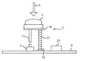
図1と図2は、本発明の第1の実施形態に係る指令用ボタン装置(プッシュボタン式)1を示す。ボタン装置1は、例えば指で押すことのできる可動部分(またはボタン本体)3を有している。図1に示すように、可動部分3は、ユーザが押すときに楽な姿勢をとりうるよう、上面が湾曲しているのが好ましい。 1 and 2 show a command button device (push button type) 1 according to a first embodiment of the present invention. The
可動部分3は、図1において矢印5で示すように、概ね垂直方向に変位することができる。この「垂直」の語は、図1と図2に示すプッシュ式のボタン装置1についていうものであって、制御ユニットと一体化された場合のボタン装置1についていうものではない。 The
ボタン装置1は、基板9に取り付けられた「プッシュ」タイプのスイッチ7を備えている。スイッチ7は、可動部分3が変位したときに、このスイッチ7と接触するよう、可動部分3の真下に取り付けられている。 The
可動部分3と関連づけられたロッド11は、スイッチ7と可動部分3の間に位置している。ロッド11は、可動部分3へ加えられた押す力を、スイッチ7へ伝える。ロッド11は、スイッチ7を基板9よりも高い位置に設けたときには、省略することもできる。 A
図2に示すように、ロッド11には、スイッチ7との接触を確実にするために、大径の当接面13を設けることができる。 As shown in FIG. 2, the
ボタン装置1は、可動部分3と関連づけられた金属板(金属の表面)15を有している。金属板15は、可動部分3の下面に取り付けられている。金属板15、および基板9上に取り付けられた金属製の受け板19には、導体材料から形成された圧縮ばね17が当接している。金属板15と受け板19は、銅またはその合金から形成するのが好ましい。圧縮ばね17は、矢印5で示す可動部分3の移動方向(概ね垂直方向)にのみ伸縮する。 The
金属板15と受け板19は、圧縮ばね17の押す力により、可動部分3が変位するときでも、常時、互いに電気的に接触している。 Even when the
この実施形態の変形例においては、ばね17の垂直方向における姿勢の維持と、ばね17を圧縮する際の案内のために、ばね17の中心部に、補助的なロッド(図示せず)を挿入する。 In a modification of this embodiment, an auxiliary rod (not shown) is inserted in the center of the
受け板19は、静電容量の測定器と接続される。この測定器は、金属板15における静電容量の変化を検出することができる。静電容量の変化は、例えば、可動部分3に指が触れることによって生じる。この実施形態においては、この測定器は、基板9のプリント回路として実現されている。このプリント回路は、基板9に埋設されるものでも、基板9に取り付けられるものでもよい。 The
受け板19には、導線を介して、端子21が接続されている。ボタン装置1は、金属板15における静電容量が変化すると、端子21に検知信号を送る。静電容量の変化は、例えば、ユーザが可動部分3に指を置いたときに生じる。 A
この実施形態においては、端子21は、基板9に取り付けられているが、他の箇所に配置することもできる。また、受け板19と端子21は、プリント回路を介して接続することもできる。 In this embodiment, the
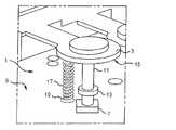
図3と図4は、本発明の第2の実施形態に係る指令用ボタン装置(回転摘み式)23を示す。このボタン装置23は、矢印29で示すように、垂直軸27の回りに回転しうる可動部分25を有している。 3 and 4 show a command button device (rotary knob type) 23 according to a second embodiment of the present invention. The
可動部分25は、カップまたは貝殻状、すなわち半球形であり、プラスチック材料から形成されている。ただし、他の形状とすることも可能である。 The
また、ボタン装置23は、トランスデューサとして、可動部分25に接続されたエンコーダ31を備えている。エンコーダ31は、可動部分25の回転運動に応答して、電気信号を発する。 The
ロッド33は、可動部分25の一部をなしており、かつ可動部分25に固着されている。 The
エンコーダ31は、前実施形態と類似の基板9に取り付けられている。可動部分25の近傍には、概ね半球形で金属製の第1の椀体37を設置してある。第1の椀体37は、可動部分25の下方にあって、これと補形をなしている。 The
第1の椀体37は、これと同様の半球形面を有する第2の椀体39によって支持されている。第2の椀体39は、基板9と当接する円筒形部分43を有している。第1の椀体37は、第2の椀体39に金属を蒸着させるか、またはめっきすることによっても得ることができる。 The
第1の椀体37は、この静電容量の変化を検知して、かつこれに応答しうる静電容量の測定器と接続されている。この測定器は、基板9に形成されたプリント回路(図示せず)からなっている。プリント回路は、基板9に埋設されるものでも、これに取り付けられるものでもよい。 The
第2の椀体39の直下領域に、プリント回路と接続された金属製の受け板45が設けられている。受け板45は、銅またはこの合金から形成するのが好ましいが、他の導電材料から形成することもできる。 A
第2の椀体39の外表面には、第1の椀体37から受け板45へ向かう金属製の電気接続部47が設けられている。電気接続部47は、第2の椀体39の内表面に設けることもできる。 On the outer surface of the
受け板45には、導線を介して、端子48が接続されている。ボタン装置23は、第1の椀体37における静電容量が変化すると、端子48に検知信号を送る。静電容量の変化は、例えば、ユーザが可動部分25に指を置いたときに生じる。 A terminal 48 is connected to the receiving
この実施形態においては、端子48は、基板9に取り付けられているが、他の箇所に配置することもできる。また、受け板45と端子48は、プリント回路を介して接続することもできる。 In this embodiment, the terminal 48 is attached to the substrate 9, but it can also be arranged at other locations. The receiving
可動部分25と第1の椀体37の間に空気の層が存在する場合でも、静電容量測定器が影響を受けることはほとんどない。すなわち、このような空気の層が存在しても、可動部分に指が触れたことを感知するのに支障を生ずることはない。 Even when an air layer exists between the
可動部分25は、垂直軸27に沿って移動しうるようにすることもできる。図3においては、このような垂直方向の移動を、矢印49と、可動部分25の破線による外形によって示してある。トランスデューサの機能を果たすエンコーダ31は、前実施形態における「プッシュボタン」タイプのボタン装置に対応するスイッチも備えている。この場合、プッシュボタンの行程として、第1の椀体37と可動部分25の間に、距離dを確保する。 The
図5は、図1と図2に示すボタン装置1の制御装置51を示すブロック図である。制御装置51は、端子21を介して静電容量測定器53と接続されたマイクロコントローラ52を備えている。マイクロコントローラ52は、補助端子55を介して、スイッチ7とも接続されている。 FIG. 5 is a block diagram showing the
制御装置51は、ボタン装置1に指が触れたこと、およびスイッチ7の作動を検知する。制御装置51は、端子57および情報網58を介して、指令装置と接続することもできる。 The
制御装置51は、ボタン装置1と関連づけられたスイッチ7が作動する前に、ボタン装置1に指が触れたことを示すディスプレー装置と接続することもできる。これは、ユーザの注意が、ボタン装置よりも、ディスプレー装置の画面に向けられた方が好ましい場合に有益である。 The
図6は、図3と図4に示すボタン装置23の制御装置59を示すブロック図である。制御装置59は、端子48を介して静電容量測定器63と接続されたマイクロコントローラ61を備えている。マイクロコントローラ61は、補助端子65を介して、エンコーダ31とも接続されている。 FIG. 6 is a block diagram showing the
制御装置59は、可動部分25に指が触れたこと、および可動部分25の回転角度を検知し、仮に可動部分25が垂直方向に移動するタイプの場合には、回転角度の代わりに、スイッチの作動を検知する。 The
制御装置51は、端子67および情報網69を介して、指令装置と接続することもできる。 The
制御装置51は、ボタン装置23における摘みの回転運動または直進運動を表示するディスプレー装置と接続することができる。ディスプレー装置の画面は、摘みに指が触れたことを感知した旨を映し出す。 The
制御装置51,59とそれぞれ接続されたボタン装置1,23は、例えば自動車のダッシュボードに組み込むことができる。ダッシュボードには、ボタン装置1,23の作動を表示するディスプレー装置を取り付けることができる。ボタン装置1,23を表示する画面は、ユーザの指が触れたことを明らかにする。したがって、ユーザは、ボタンを見なくても、ボタン装置の作動の様子を知ることができる。 The
ディスプレー装置は、ユーザが、前方への注意をそらさなくても、これを見ることができるように、ダッシュボードに取り付けるのが好ましい。また、制御装置は、カーエアコン、カーオーディオ、カーラジオ、カーナビゲーション等のダッシュボードに組み込める装置向けのものとするのが好ましい。 The display device is preferably attached to the dashboard so that the user can see it without diverting forward attention. The control device is preferably for a device that can be incorporated into a dashboard such as a car air conditioner, a car audio, a car radio, or a car navigation system.
本発明に係るボタン装置は、上記の実施形態以外のものとすることも可能である。ユーザが指を触れる可動部分は、スライド式のものやレバーとすることもできる。 The button device according to the present invention may be other than the above embodiment. The movable part with which the user touches the finger may be a slide type or a lever.
制御装置51,59は、制御ユニットにおける1つの構成要素とすることもできる。一般に、制御装置51,59は、複数のボタン装置1,23と接続される。 The
本発明に係るボタン装置は、制御装置への指令を、手探りで行いうるようにするためのものである(作動の様子は、ディスプレー装置に表示される)。 The button device according to the present invention is to enable a command to the control device to be carried out by hand search (the state of operation is displayed on the display device).
本発明は、上記実施形態に限定されるものではなく、当業者には自明の変形例も、本発明の技術的範囲に含まれる。 The present invention is not limited to the embodiment described above, and modifications obvious to those skilled in the art are also included in the technical scope of the present invention.
1 ボタン装置
3 可動部分
7 スイッチ
9 基板
11 ロッド
13 当接面
15 金属板
17 圧縮ばね
19 受け板
21 端子
23 ボタン装置
25 可動部分
31 エンコーダ
33 ロッド
37 第1の椀体
39 第2の椀体
45 受け板
47 電気接続部
48 端子
51 制御装置
52 マイクロコントローラ
53 静電容量測定器
55 補助端子
58 情報網
59 制御装置
61 マイクロコントローラ
65 補助端子
67 端子
69 情報網1
11 Rod
13 Contact surface
15 Metal plate
17 Compression spring
19 Back plate
21 terminals
23 button device
25 Moving parts
31 Encoder
33 Rod
37 First housing
39 Second enclosure
45 Back plate
47 Electrical connection
48 terminals
51 Control unit
52 Microcontroller
53 Capacitance measuring instrument
55 Auxiliary terminal
58 Information network
59 Controller
61 Microcontroller
65 Auxiliary terminal
67 terminals
69 Information network
Claims (14)
Translated fromJapaneseApplications Claiming Priority (2)
| Application Number | Priority Date | Filing Date | Title |
|---|---|---|---|
| FR0509027 | 2005-09-02 | ||
| FR0509027AFR2890488B1 (en) | 2005-09-02 | 2005-09-02 | CONTROL BUTTON WITH PRESENCE DETECTION. |
Publications (2)
| Publication Number | Publication Date |
|---|---|
| JP2007073506Atrue JP2007073506A (en) | 2007-03-22 |
| JP4966609B2 JP4966609B2 (en) | 2012-07-04 |
Family
ID=36498906
Family Applications (1)
| Application Number | Title | Priority Date | Filing Date |
|---|---|---|---|
| JP2006229968AExpired - Fee RelatedJP4966609B2 (en) | 2005-09-02 | 2006-08-28 | Command button device capable of sensing contact |
Country Status (7)
| Country | Link |
|---|---|
| US (1) | US7920122B2 (en) |
| EP (1) | EP1760738B1 (en) |
| JP (1) | JP4966609B2 (en) |
| CN (1) | CN1925081B (en) |
| AT (1) | ATE529872T1 (en) |
| ES (1) | ES2375732T3 (en) |
| FR (1) | FR2890488B1 (en) |
Cited By (5)
| Publication number | Priority date | Publication date | Assignee | Title |
|---|---|---|---|---|
| JP2010171009A (en)* | 2009-01-22 | 2010-08-05 | Ego Elektro Geraete Blanc & Fischer | Operation device for electric appliance |
| DE102010034552A1 (en) | 2009-08-21 | 2011-02-24 | Alps Electric Co., Ltd. | Trigger switch with capacitance sensor and input device equipped therewith |
| US8355304B2 (en) | 2006-03-03 | 2013-01-15 | Sharp Kabushiki Kaisha | Optical information recording medium, reproducing device for optical information recording medium, control method and control program for the reproducing device, and medium with the control program recorded therein |
| US8705333B2 (en) | 2007-08-30 | 2014-04-22 | Sharp Kabushiki Kaisha | Super-resolution optical recording medium on which information is recorded using train of prepits, optical recording medium reproduction device, and control method |
| JP2017157462A (en)* | 2016-03-03 | 2017-09-07 | アルプス電気株式会社 | Input device |
Families Citing this family (3)
| Publication number | Priority date | Publication date | Assignee | Title |
|---|---|---|---|---|
| DE102007025564A1 (en)* | 2006-06-07 | 2007-12-13 | Preh Gmbh | Operating element for a motor vehicle |
| CN104990701B (en)* | 2015-07-21 | 2018-03-30 | 上海福宇龙汽车科技有限公司 | Car panel button keys force test device and method |
| IT201800002535A1 (en)* | 2018-02-09 | 2019-08-09 | Bitron Spa | CAPACITIVE KEY AND RELATIVE CAPACITIVE CONTROL KEYBOARD. |
Citations (3)
| Publication number | Priority date | Publication date | Assignee | Title |
|---|---|---|---|---|
| JPH04118826A (en)* | 1990-09-06 | 1992-04-20 | Mitsubishi Denki Shomei Kk | touch switch |
| US5541622A (en)* | 1990-07-24 | 1996-07-30 | Incontrol Solutions, Inc. | Miniature isometric joystick |
| JP2002034093A (en)* | 2000-04-11 | 2002-01-31 | Flux Research Pty Ltd | Controller |
Family Cites Families (4)
| Publication number | Priority date | Publication date | Assignee | Title |
|---|---|---|---|---|
| DE3910977A1 (en)* | 1989-04-05 | 1990-10-11 | Harms & Wende Gmbh U Co Kg | Computer input device |
| US6040821A (en)* | 1989-09-26 | 2000-03-21 | Incontrol Solutions, Inc. | Cursor tracking |
| US6154201A (en)* | 1996-11-26 | 2000-11-28 | Immersion Corporation | Control knob with multiple degrees of freedom and force feedback |
| US7369119B2 (en)* | 2004-06-24 | 2008-05-06 | Motorola, Inc. | Handset device with dual side joystick |
- 2005
- 2005-09-02FRFR0509027Apatent/FR2890488B1/ennot_activeExpired - Fee Related
- 2006
- 2006-08-14USUS11/503,642patent/US7920122B2/enactiveActive
- 2006-08-17ESES06119100Tpatent/ES2375732T3/enactiveActive
- 2006-08-17ATAT06119100Tpatent/ATE529872T1/ennot_activeIP Right Cessation
- 2006-08-17EPEP06119100Apatent/EP1760738B1/ennot_activeNot-in-force
- 2006-08-28JPJP2006229968Apatent/JP4966609B2/ennot_activeExpired - Fee Related
- 2006-09-01CNCN2006101266968Apatent/CN1925081B/ennot_activeExpired - Fee Related
Patent Citations (3)
| Publication number | Priority date | Publication date | Assignee | Title |
|---|---|---|---|---|
| US5541622A (en)* | 1990-07-24 | 1996-07-30 | Incontrol Solutions, Inc. | Miniature isometric joystick |
| JPH04118826A (en)* | 1990-09-06 | 1992-04-20 | Mitsubishi Denki Shomei Kk | touch switch |
| JP2002034093A (en)* | 2000-04-11 | 2002-01-31 | Flux Research Pty Ltd | Controller |
Cited By (10)
| Publication number | Priority date | Publication date | Assignee | Title |
|---|---|---|---|---|
| US8355304B2 (en) | 2006-03-03 | 2013-01-15 | Sharp Kabushiki Kaisha | Optical information recording medium, reproducing device for optical information recording medium, control method and control program for the reproducing device, and medium with the control program recorded therein |
| US8400903B2 (en) | 2006-03-03 | 2013-03-19 | Sharp Kabushiki Kaisha | Optical information recording medium, reproducing device for optical information recording medium, control method and control program for the reproducing device, and medium with the control program recorded therein |
| US8462606B2 (en) | 2006-03-03 | 2013-06-11 | Sharp Kabushiki Kaisha | Optical information recording medium, reproducing device for optical information recording medium, control method and control program for the reproducing device, and medium with the control program recorded therein |
| US8705333B2 (en) | 2007-08-30 | 2014-04-22 | Sharp Kabushiki Kaisha | Super-resolution optical recording medium on which information is recorded using train of prepits, optical recording medium reproduction device, and control method |
| US8867328B2 (en) | 2007-08-30 | 2014-10-21 | Sharp Kabushiki Kaisha | Optical recording medium on which information is recorded using train of prepits, and method for reproducing optical recording medium |
| JP2010171009A (en)* | 2009-01-22 | 2010-08-05 | Ego Elektro Geraete Blanc & Fischer | Operation device for electric appliance |
| DE102010034552A1 (en) | 2009-08-21 | 2011-02-24 | Alps Electric Co., Ltd. | Trigger switch with capacitance sensor and input device equipped therewith |
| JP2011044362A (en)* | 2009-08-21 | 2011-03-03 | Alps Electric Co Ltd | Push switch with capacitance sensor and input device employing the same |
| DE102010034552B4 (en)* | 2009-08-21 | 2013-09-12 | Alps Electric Co., Ltd. | Trigger switch with capacitance sensor and input device equipped therewith |
| JP2017157462A (en)* | 2016-03-03 | 2017-09-07 | アルプス電気株式会社 | Input device |
Also Published As
| Publication number | Publication date |
|---|---|
| EP1760738A1 (en) | 2007-03-07 |
| EP1760738B1 (en) | 2011-10-19 |
| FR2890488B1 (en) | 2008-12-26 |
| US7920122B2 (en) | 2011-04-05 |
| US20070052598A1 (en) | 2007-03-08 |
| ATE529872T1 (en) | 2011-11-15 |
| FR2890488A1 (en) | 2007-03-09 |
| JP4966609B2 (en) | 2012-07-04 |
| CN1925081A (en) | 2007-03-07 |
| ES2375732T3 (en) | 2012-03-05 |
| CN1925081B (en) | 2010-12-08 |
Similar Documents
| Publication | Publication Date | Title |
|---|---|---|
| JP4966609B2 (en) | Command button device capable of sensing contact | |
| JP4377343B2 (en) | Touch operation input device | |
| US9182825B2 (en) | Input device comprising a touch-sensitive input surface | |
| JP5326569B2 (en) | Input device | |
| US20090115748A1 (en) | Inputting device | |
| CN101681212A (en) | Screen assembly | |
| CN104898762B (en) | Operation device | |
| TW200822682A (en) | Multi-function key with scrolling | |
| EP2207078A1 (en) | Input device and electronic apparatus mounting the same | |
| KR20080108970A (en) | Interactive operating device and method for operating the interactive operating device | |
| JP6622264B2 (en) | In-vehicle device operation support system | |
| JP2011526385A (en) | Input device having touch-sensitive input device and rotary input device | |
| EP2502129A1 (en) | Hand-held input device, system comprising the input device and an electronic device and method for controlling the same | |
| CN105683869A (en) | Operating device that can be operated without keys | |
| US20090033514A1 (en) | Remote controller | |
| JP5147821B2 (en) | Input device | |
| JP5954145B2 (en) | Input device | |
| JP6754673B2 (en) | Electronic device with toggle switch | |
| JP6610452B2 (en) | Vehicle display device | |
| WO2006105242A2 (en) | Improved mobile communication terminal and method | |
| JP2006120009A (en) | Information operation device | |
| CN110870204B (en) | Operating device for a motor vehicle, method for operating a motor vehicle with the aid of an operating device, control device and motor vehicle | |
| EP1246126A2 (en) | Input device capable of generating different input signals on single operating surface | |
| US20200133396A1 (en) | A motor vehicle operating unit and a method of confirming a switching command | |
| JP2011023286A (en) | Switch device |
Legal Events
| Date | Code | Title | Description |
|---|---|---|---|
| A621 | Written request for application examination | Free format text:JAPANESE INTERMEDIATE CODE: A621 Effective date:20090804 | |
| A977 | Report on retrieval | Free format text:JAPANESE INTERMEDIATE CODE: A971007 Effective date:20110623 | |
| A131 | Notification of reasons for refusal | Free format text:JAPANESE INTERMEDIATE CODE: A131 Effective date:20110705 | |
| A601 | Written request for extension of time | Free format text:JAPANESE INTERMEDIATE CODE: A601 Effective date:20110929 | |
| A602 | Written permission of extension of time | Free format text:JAPANESE INTERMEDIATE CODE: A602 Effective date:20111004 | |
| A521 | Written amendment | Free format text:JAPANESE INTERMEDIATE CODE: A523 Effective date:20120105 | |
| TRDD | Decision of grant or rejection written | ||
| A01 | Written decision to grant a patent or to grant a registration (utility model) | Free format text:JAPANESE INTERMEDIATE CODE: A01 Effective date:20120313 | |
| A01 | Written decision to grant a patent or to grant a registration (utility model) | Free format text:JAPANESE INTERMEDIATE CODE: A01 | |
| A61 | First payment of annual fees (during grant procedure) | Free format text:JAPANESE INTERMEDIATE CODE: A61 Effective date:20120402 | |
| R150 | Certificate of patent or registration of utility model | Free format text:JAPANESE INTERMEDIATE CODE: R150 | |
| FPAY | Renewal fee payment (event date is renewal date of database) | Free format text:PAYMENT UNTIL: 20150406 Year of fee payment:3 | |
| LAPS | Cancellation because of no payment of annual fees |