JP2007072988A - Disk array device, data movement method, and program - Google Patents
Disk array device, data movement method, and programDownload PDFInfo
- Publication number
- JP2007072988A JP2007072988AJP2005262318AJP2005262318AJP2007072988AJP 2007072988 AJP2007072988 AJP 2007072988AJP 2005262318 AJP2005262318 AJP 2005262318AJP 2005262318 AJP2005262318 AJP 2005262318AJP 2007072988 AJP2007072988 AJP 2007072988A
- Authority
- JP
- Japan
- Prior art keywords
- data movement
- data
- time
- movement amount
- migration
- Prior art date
- Legal status (The legal status is an assumption and is not a legal conclusion. Google has not performed a legal analysis and makes no representation as to the accuracy of the status listed.)
- Pending
Links
Images


Classifications
- G—PHYSICS
- G06—COMPUTING OR CALCULATING; COUNTING
- G06F—ELECTRIC DIGITAL DATA PROCESSING
- G06F3/00—Input arrangements for transferring data to be processed into a form capable of being handled by the computer; Output arrangements for transferring data from processing unit to output unit, e.g. interface arrangements
- G06F3/06—Digital input from, or digital output to, record carriers, e.g. RAID, emulated record carriers or networked record carriers
- G06F3/0601—Interfaces specially adapted for storage systems
- G06F3/0628—Interfaces specially adapted for storage systems making use of a particular technique
- G06F3/0646—Horizontal data movement in storage systems, i.e. moving data in between storage devices or systems
- G06F3/0647—Migration mechanisms
- G06F3/0649—Lifecycle management
- G—PHYSICS
- G06—COMPUTING OR CALCULATING; COUNTING
- G06F—ELECTRIC DIGITAL DATA PROCESSING
- G06F3/00—Input arrangements for transferring data to be processed into a form capable of being handled by the computer; Output arrangements for transferring data from processing unit to output unit, e.g. interface arrangements
- G06F3/06—Digital input from, or digital output to, record carriers, e.g. RAID, emulated record carriers or networked record carriers
- G06F3/0601—Interfaces specially adapted for storage systems
- G06F3/0602—Interfaces specially adapted for storage systems specifically adapted to achieve a particular effect
- G06F3/0604—Improving or facilitating administration, e.g. storage management
- G06F3/0605—Improving or facilitating administration, e.g. storage management by facilitating the interaction with a user or administrator
- G—PHYSICS
- G06—COMPUTING OR CALCULATING; COUNTING
- G06F—ELECTRIC DIGITAL DATA PROCESSING
- G06F3/00—Input arrangements for transferring data to be processed into a form capable of being handled by the computer; Output arrangements for transferring data from processing unit to output unit, e.g. interface arrangements
- G06F3/06—Digital input from, or digital output to, record carriers, e.g. RAID, emulated record carriers or networked record carriers
- G06F3/0601—Interfaces specially adapted for storage systems
- G06F3/0668—Interfaces specially adapted for storage systems adopting a particular infrastructure
- G06F3/0671—In-line storage system
- G06F3/0683—Plurality of storage devices
- G06F3/0689—Disk arrays, e.g. RAID, JBOD
Landscapes
- Engineering & Computer Science (AREA)
- Theoretical Computer Science (AREA)
- Human Computer Interaction (AREA)
- Physics & Mathematics (AREA)
- General Engineering & Computer Science (AREA)
- General Physics & Mathematics (AREA)
- Information Retrieval, Db Structures And Fs Structures Therefor (AREA)
Abstract
Translated fromJapaneseDescription
Translated fromJapanese本発明は、ディスクアレイ装置及びデータ移動方法並びにプログラムに関し、例えば、複数のディスクアレイ装置間において、データを移動させるストレージシステムに適用して好適なものである。 The present invention relates to a disk array device, a data movement method, and a program, and is suitably applied to, for example, a storage system that moves data between a plurality of disk array devices.
近年、企業等で取り扱うデータの爆発的増大に伴い、複数のディスクアレイ装置をSAN(Storage Area Network)等により相互に接続することによって、大容量のデータを記憶するストレージシステムが広く普及している。 In recent years, with the explosive increase in data handled by companies, storage systems for storing large amounts of data by connecting a plurality of disk array devices to each other via a SAN (Storage Area Network) or the like have become widespread. .
このようなストレージシステムでは、複数のディスクアレイ装置を管理する情報処理装置によって、各ディスクアレイ装置におけるデータ配置の最適化を行うといったことがなされている。 In such a storage system, the data arrangement in each disk array device is optimized by an information processing device that manages a plurality of disk array devices.
例えば、データ配置の最適化を行うストレージシステムとして、情報処理装置に各ディスクアレイ装置の製造元情報及び使用状況情報を取得させて、当該製造元情報及び使用状況情報に基づいて、個々のディスクアレイ装置内の記憶領域間、及び各ディスクアレイ装置の記憶領域間におけるデータ移動を行うストレージシステムが提案されている(例えば、特許文献1参照)。
ところで、さらに近年では、ストレージシステムについて、データライフサイクルマネージメント(Data Lifecycle Management:DLCM)という概念が提唱されている。このデータライフサイクルマネージメントでは、データの価値が時間を経るにつれて変化するという事実に着目して、データの効率的な保存管理を行うというものである。 Incidentally, in recent years, the concept of data lifecycle management (DLCM) has been proposed for storage systems. In this data life cycle management, efficient storage management of data is performed by paying attention to the fact that the value of data changes with time.
このデータライフサイクルマネージメントでは、例えば、価値が低下したデータを高価な記憶デバイスに記憶させておくのは記憶資源の浪費であるため、このような価値が低下したデータを、信頼性、応答性及び耐久性について高価な記憶デバイスに劣る安価な記憶デバイスに移動させるということが行われている。 In this data life cycle management, for example, it is a waste of storage resources to store data with a reduced value in an expensive storage device. In terms of durability, moving to an inexpensive storage device inferior to an expensive storage device has been performed.
このような、ストレージシステムにおいて、例えば、高価な記憶デバイスの記憶領域に記憶されているデータを、週ごと、月ごと等の一定期間ごとの指定された日時に安価な記憶デバイスに移動させるような場合には、できるだけその指定された日時においてデータの移動を終了させることが望ましい。 In such a storage system, for example, data stored in a storage area of an expensive storage device is moved to an inexpensive storage device at a designated date and time for a certain period such as weekly or monthly. In some cases, it is desirable to end the movement of data at the designated date and time as much as possible.
しかしながら、指定された日時においてデータの移動を終了させるような場合には、データ移動時における転送速度等の要因により、移動開始時刻を推測することが難しいという問題があり、この結果、指定された時刻においてデータの移動を終了させることが困難となっている。 However, when data movement is terminated at the specified date and time, there is a problem that it is difficult to estimate the movement start time due to factors such as the transfer speed at the time of data movement. It is difficult to end the movement of data at the time.
このように、指定された日時においてデータの移動を終了させることが困難であるため、ユーザが移動終了時間を推測して移動開始時刻を設定しなければならず、操作が煩雑となると共に、データの移動を終了させることができなかった場合を想定して、予備の記憶領域を高価な記憶デバイス内に用意しておかなければならず、高価な記憶デバイスを効率的に使用することができないという問題がある。 As described above, since it is difficult to end the movement of data at the designated date and time, the user must set the movement start time by estimating the movement end time, and the operation becomes complicated and the data Assuming that the movement of the storage device could not be completed, a spare storage area must be prepared in an expensive storage device, and the expensive storage device cannot be used efficiently. There's a problem.
本発明は以上の点を考慮してなされたもので、操作性を格段的に向上させ得るディスクアレイ装置及びデータ移動方法並びにプログラムを提案するものである。 The present invention has been made in consideration of the above points, and proposes a disk array device, a data movement method, and a program that can remarkably improve operability.
かかる課題を解決するために本発明においては、データを移動させる際の移動元となる移動元ボリュームを有し、当該移動元ボリュームから、移動先となる他の移動先ボリュームに前記データを移動させるディスクアレイ装置であって、外部操作によりデータ移動終了日時の指定があったときに、前記データ移動終了日時から所定時間ごとに遡った時間帯ごとにおける前記移動元ボリュームへのアクセス頻度を算出するアクセス頻度算出部と、前記アクセス頻度算出部により算出されたアクセス頻度に基づいて、前記時間帯ごとにおける予想データ移動量を算出する予想データ移動量算出部と、前記予想データ移動量算出部により算出された予想データ移動量に基づいて、データ移動開始日時を算出するデータ移動開始日時算出部とを備えるようにした。 In order to solve this problem, the present invention has a migration source volume as a migration source when data is migrated, and moves the data from the migration source volume to another migration destination volume as a migration destination. An access that calculates the access frequency to the migration source volume in each time zone that is traced back every predetermined time from the data migration end date and time when the data migration end date and time is specified by an external operation in the disk array device Calculated by a frequency calculation unit, an expected data movement amount calculation unit that calculates an expected data movement amount for each time period based on the access frequency calculated by the access frequency calculation unit, and the predicted data movement amount calculation unit A data movement start date and time calculation unit for calculating a data movement start date and time based on the predicted data movement amount Was Unishi.
従って、ユーザがデータ移動終了日時を推測してデータ移動開始日時を設定することなく、データ移動終了日時を指定するだけで、当該データ移動終了日時にデータ移動を終了するようなデータ移動開始日時を設定することができる。 Therefore, without specifying the data movement start date and time by guessing the data movement end date and time, the user only specifies the data movement end date and time, so that the data movement start date and time for ending the data movement at the data movement end date and time is set. Can be set.
また、本発明においては、データを移動させる際の移動元となる移動元ボリュームを有し、当該移動元ボリュームから、移動先となる他の移動先ボリュームに前記データを移動させるディスクアレイ装置のデータ移動方法であって、外部操作によりデータ移動終了日時の指定があったときに、前記データ移動終了日時から所定時間ごとに遡った時間帯ごとにおける前記移動元ボリュームへのアクセス頻度を算出する第1のステップと、前記第1のステップにおいて算出したアクセス頻度に基づいて、前記時間帯ごとにおける予想データ移動量を算出する第2のステップと、前記第2のステップにおいて算出した予想データ移動量に基づいて、データ移動開始日時を算出する第3のステップとを備えるようにした。 In the present invention, the data of a disk array device that has a migration source volume as a migration source when data is migrated and moves the data from the migration source volume to another migration destination volume as a migration destination A migration method is a first method of calculating an access frequency to the migration source volume in each time zone that is traced back every predetermined time from the data migration end date and time when the data migration end date and time is designated by an external operation. The second step of calculating the predicted data movement amount for each time period based on the access frequency calculated in the first step, and the predicted data movement amount calculated in the second step. And a third step of calculating the data movement start date and time.
従って、ユーザがデータ移動終了日時を推測してデータ移動開始日時を設定することなく、データ移動終了日時を指定するだけで、当該データ移動終了日時にデータ移動を終了するようなデータ移動開始日時を設定することができる。 Therefore, without specifying the data movement start date and time by guessing the data movement end date and time, the user only specifies the data movement end date and time, so that the data movement start date and time for ending the data movement at the data movement end date and time is set. Can be set.
さらに、本発明においては、データを移動させる際の移動元となる移動元ボリュームを有し、当該移動元ボリュームから、移動先となる他の移動先ボリュームに前記データを移動させるディスクアレイ装置に対して、プログラムによって、外部操作によりデータ移動終了日時の指定があったときに、前記データ移動終了日時から所定時間ごとに遡った時間帯ごとにおける前記移動元ボリュームへのアクセス頻度を算出する第1のステップと、前記第1のステップにおいて算出したアクセス頻度に基づいて、前記時間帯ごとにおける予想データ移動量を算出する第2のステップと、前記第2のステップにおいて算出した予想データ移動量に基づいて、データ移動開始日時を算出する第3のステップとを実行させるようにした。 Further, in the present invention, a disk array device having a migration source volume as a migration source when data is migrated and moving the data from the migration source volume to another migration destination volume as a migration destination is provided. Then, when the data movement end date / time is designated by an external operation by the program, the access frequency to the movement source volume is calculated for each time zone that goes back every predetermined time from the data movement end date / time. A step, a second step of calculating an expected data movement amount for each time period based on the access frequency calculated in the first step, and a predicted data movement amount calculated in the second step. The third step of calculating the data movement start date and time is executed.
従って、ユーザがデータ移動終了日時を推測してデータ移動開始日時を設定することなく、データ移動終了日時を指定するだけで、当該データ移動終了日時にデータ移動を終了するようなデータ移動開始日時を設定することができる。 Therefore, without specifying the data movement start date and time by guessing the data movement end date and time, the user only specifies the data movement end date and time, so that the data movement start date and time for ending the data movement at the data movement end date and time is set. Can be set.
本発明によれば、外部操作によりデータ移動終了日時の指定があったときに、前記データ移動終了日時から所定時間ごとに遡った時間帯ごとにおける前記移動元ボリュームへのアクセス頻度を算出し、このアクセス頻度に基づいて、前記時間帯ごとにおける予想データ移動量を算出して、かかる予想データ移動量に基づいて、データ移動開始日時を算出することにより、ユーザがデータ移動終了日時を推測してデータ移動開始日時を設定することなく、データ移動終了日時を指定するだけで、当該データ移動終了日時にデータ移動を終了するようなデータ移動開始日時を設定することができ、操作性を格段的に向上させ得るディスクアレイ装置及びデータ移動方法並びにプログラムを実現できる。 According to the present invention, when the data movement end date and time is designated by an external operation, the access frequency to the migration source volume is calculated for each time period that is traced back every predetermined time from the data movement end date and time. Based on the access frequency, the estimated data movement amount for each time period is calculated, and the data movement start date and time is calculated based on the predicted data movement amount, so that the user can estimate the data movement end date and time and By simply specifying the data movement end date and time without setting the movement start date and time, it is possible to set the data movement start date and time to end the data movement at the data movement end date and time, which greatly improves operability. The disk array device, data movement method and program can be realized.
以下図面について、本発明の一実施の形態を詳述する。 Hereinafter, an embodiment of the present invention will be described in detail with reference to the drawings.
(1)本実施の形態によるストレージシステムの構成
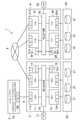
図1は、本実施の形態によるストレージシステム1のシステム構成を示している。このストレージシステム1は、ホストシステム2と、第1の記憶制御装置3と、第2の記憶制御装置4とを備えて構成されており、ホストシステム2からのコマンドに応じてデータ処理を行うようになされている。第1の記憶制御装置3及び第2の記憶制御装置4は、第1の通信ネットワーク5を介して相互接続されており、それぞれが共に同一サイトに設置されていてもよく、或いはそれぞれが異なるサイトに設置されていてもよい。(1) Configuration of Storage System According to this Embodiment FIG. 1 shows the system configuration of the
ホストシステム2は、例えば、CPU(Central Processing Unit)やメモリ等を備えた上位装置であり、具体的には、パーソナルコンピュータ、ワークステーション、メインフレーム等である。更に、ホストシステム2には、例えば、アプリケーションプログラム2Aと、第2の通信ネットワーク6を介して第1の記憶制御装置3にアクセスするためのポート2Bとが実装されている。アプリケーションプログラム2Aとしては、例えば、第1の記憶制御装置3が提供する記憶資源を利用するデータベース等のアプリケーションプログラムの他、第1の記憶制御装置3の記憶資源を管理する管理用のアプリケーションプログラム等がある。 The
ホストシステム2は、第2の通信ネットワーク6を介して、第1の記憶制御装置3に相互接続されている。通信ネットワーク6としては、例えば、LAN(Local Area Network)、SAN(Storage Area Network)、インターネット、専用回線、公衆回線等を適宜用いることができる。LANを介するデータ通信は、例えば、TCP/IP(Transmission Control Protocol/Internet Protocol)プロトコルに従って行われる。ホストシステム2がLANを介して第1の記憶制御装置3に接続される場合、ホストシステム2は、ファイル名を指定してファイル単位でのデータ入出力を要求する。一方、ホストシステム2がSANを介して第1の記憶制御装置3に接続される場合、ホストシステム2は、ファイバチャネルプロトコルに従って、複数のディスクドライブにより提供される記憶資源のデータ管理単位であるブロックを単位として、データ入出力を要求する。第2の通信ネットワーク6がLANである場合、ポート2Bは、例えば、LAN対応のネットワークカードである。第2の通信ネットワーク6がSANの場合、ポート2Bは、例えば、HBA(Host Bus Adapter)である。 The
第1の記憶制御装置3は、複数のチャネルアダプタ(CHA)11と、複数のディスクアダプタ(DKA)12と、管理端末(SVP)13と、キャッシュメモリ(CM)14と、共有メモリ(SM)15と、相互結合網16とを備えている。 The
各々のチャネルアダプタ11は、例えば、それぞれマイクロプロセッサ(Micro Processor)や内部メモリ等を備えたマイクロコンピュータシステムとして構成され、ホストシステム2との間のデータ通信を行うためのポート11Aを備えている。チャネルアダプタ11は、ホストシステム2から受信した各種コマンドを解釈して実行する。チャネルアダプタ11には、固有のネットワークアドレス(例えば、IPアドレスやWWN(World Wide Name))が割り当てられている。各々のチャネルアダプタ11は、それぞれが個別にNAS(Network Attached Storage)として機能することができる。複数のホストシステム2が存在する場合、各々のチャネルアダプタ11は、各々のホストシステム2からの要求をそれぞれ個別に受け付けることができる。 Each
各々のディスクアダプタ12は、記憶装置20の記憶デバイス21との間のデータ授受を行う。ディスクアダプタ12は、記憶デバイス21に接続するためのポート12Aを備えている。ディスクアダプタ12は、チャネルアダプタ11がホストシステム2から受信したデータを、ホストシステム2からのライトコマンドに基づいて、記憶デバイス21の所定のアドレスに書き込む他、ホストシステム2からのリードコマンドに基づいて、記憶デバイス21の所定のアドレスからデータを読み出し、ホストシステム2に送信する。ディスクアダプタ12は、記憶デバイス21にデータを読み書きする場合、論理アドレスを物理アドレスに変換する。ディスクアダプタ12は、記憶デバイス21がRAID(Redundant Arrays of Independent Inexpensive Disks)やECC(Error Correcting Code)グループに従って管理されている場合は、RAID構成やECCグループ構成に応じたデータアクセスを行う。 Each disk adapter 12 exchanges data with the
管理端末13は、第1の記憶制御装置3を保守又は管理するための端末装置である。保守員は、管理端末13を操作することにより、例えば、記憶デバイス21上に定義される論理デバイスの設定、記憶デバイス21の増設又は減設、RAID構成やECCグループ構成の設定変更(例えば、RAIDレベル5からRAIDレベル1への変更)等を行う。 The
キャッシュメモリ14は、ホストシステム2から受信したデータや、記憶デバイス21から読み出したデータを一時的に記憶するものである。共有メモリ15には、システム管理に必要な各種の制御情報等が格納される。 The
相互結合網16は、チャネルアダプタ11,ディスクアダプタ12,管理端末13,キャッシュメモリ14,共有メモリ15を相互に接続する。相互結合網16は、例えば、高速スイッチング動作によってデータ伝送を行う超高速クロスバスイッチ等のような高速バスとして構成することができる。 The
記憶装置20は、複数の記憶デバイス21を備えている。この記憶デバイス21としては、例えば、SCSI(Small Computer System Interface)ディスクドライブやファイバチャネルディスクドライブ等の高価なディスクドライブが用いられている。記憶装置20は、複数の記憶デバイス21をアレイ状に配設して構成されるもので、記憶デバイス21群が提供する物理的な記憶領域上には、少なくとも1つ以上の論理ユニット(Logical Unit:LU)(論理ボリューム)が形成され、この論理ユニットがホストシステム2に提供される。 The
尚、同図では、ホストシステム2は、第2の通信ネットワーク6を介して第1の記憶制御装置3のみに接続される例を示しているが、ホストシステム2と第2の記憶制御装置4とを第1の通信ネットワーク5を介して相互接続してもよい。第1の通信ネットワーク5は、例えば、SAN、LAN、インターネット、専用回線、公衆回線等である。 In the figure, the
一方、第2の記憶制御装置4は、複数のチャネルアダプタ(CHA)31と、複数のディスクアダプタ(DKA)32と、管理端末(SVP)33と、キャッシュメモリ(CM)34と、共有メモリ(SM)35と、相互結合網36とを備えている。 On the other hand, the
各々のチャネルアダプタ31は、第1の通信ネットワーク5に接続するポート31Aを備える。また、各々のディスクアダプタ(DKA)32は、記憶デバイス41に接続するためのポート41Aを備える。記憶装置40は、複数の記憶デバイス41を備えている。この記憶デバイス41としては、例えば、SATA(Serial AT Attachment)ディスクや光ディスク等の安価なディスクドライブが用いられている。なお、第2の記憶制御装置4は、第1の記憶制御装置3と同様の構成を備えているので、その詳細な説明は省略する。 Each
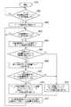
ここで、共有メモリ15は、図2に示すように、その内部に、内部タイマ50、リードI/O(Input/Output)カウンタ51、ライトI/Oカウンタ52、データ移動ペーステーブル60、I/Oカウントテーブル70、データ移動量テーブル80、日時テーブル90、論理ユニット情報データベース110、データ移動量情報データベース120、I/Oカウント情報データベース140、及びデータ移動開始日時情報データベース150を備えている。 2, the shared
内部タイマ50は、現在日時や、データ移動開始日時、データ移動終了日時等を計測することができるようになされている。また、リードI/Oカウンタ51は、論理ユニット又はECCグループに対するリードI/Oを計測することができるようになされている。さらに、ライトI/Oカウンタ52は、論理ユニット又はECCグループに対するライトI/Oを計測することができるようになされている。 The
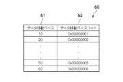
データ移動ペーステーブル60には、図3に示すように、1時間あたりにデータを移動させるペースを示すデータ移動ペース記憶欄61、及び当該データ移動ペース記憶欄61に対応してデータ移動ペースコード記憶欄62が設けられており、1時間あたりのデータ移動ペースをデータ移動ペースコードに変換することができるようになされている。 In the data movement pace table 60, as shown in FIG. 3, a data movement
I/Oカウンタテーブル70には、図4に示すように、論理ユニット又はECCグループに対する1時間あたりのリードI/O及びライトI/Oの回数を示すI/Oカウント記憶欄71、及び当該I/Oカウント記憶欄71に対応してI/Oカウントコード記憶欄72が設けられており、論理ユニット又はECCグループに対する1時間あたりのリードI/Oカウント、及びライトI/OカウントをI/Oカウントコードに変換することができるようになされている。 As shown in FIG. 4, the I / O counter table 70 includes an I / O
データ移動量テーブル80には、図5に示すように、データを出力する論理ユニット(以下、これを移動元論理ユニットと呼ぶ)から、データを入力する論理ユニット(以下、これを移動先論理ユニットと呼ぶ)にデータを移動するときの1時間あたりのデータ移動量を示すデータ移動量記憶欄81、及び当該データ移動量記憶欄81に対応してデータ移動量コード記憶欄82が設けられており、1時間あたりのデータ移動量をデータ移動量コードに変換することができるようになされている。 In the data movement amount table 80, as shown in FIG. 5, from a logical unit that outputs data (hereinafter referred to as a migration source logical unit) to a logical unit that inputs data (hereinafter referred to as a migration destination logical unit). A data movement
日時テーブル90には、図6に示すように、開始日時の日及び時刻を示す開始日時記憶欄91及び終了日時の日及び時刻を示す終了日時記憶欄92が設けられている。 As shown in FIG. 6, the date / time table 90 is provided with a start date /
開始日時記憶欄91には、開始日時の日を示す開始日記憶欄93、及び当該開始日記憶欄93に対応して開始日コード記憶欄94が設けられていると共に、開始日時の時刻を示す開始時刻記憶欄95、及び当該開始時刻記憶欄95に対応して開始時刻コード記憶欄96が設けられており、開始日及び開始時刻を開始日コード及び開始時刻コードに変換することができるようになされている。 The start date and
終了日時記憶欄92には、終了日時の日を示す終了日記憶欄97、及び当該終了日記憶欄97に対応して終了日コード記憶欄98が設けられていると共に、終了日時の時刻を示す終了時刻記憶欄99、及び当該終了時刻記憶欄99に対応して終了時刻コード記憶欄100が設けられており、終了日及び終了時刻を終了日コード及び終了時刻コードに変換することができるようになされている。 The end
論理ユニット情報データベース110は、図7に示すように、この記憶装置20の記憶デバイス21の記憶領域上に提供される論理ユニットごとに、論理ユニット情報111が格納されることにより構成されている。 As shown in FIG. 7, the logical
この論理ユニット情報111は、論理ユニットの番号である論理ユニット番号112、当該論理ユニットの属するECCグループの番号であるECCグループ番号113及び論理ユニットのデータ容量であるデータ容量114が設けられており、論理ユニット番号112、ECCグループ番号113及びデータ容量114を関連づけて論理ユニット情報データベース110で管理するようになされている。 This
データ移動量情報データベース120は、データ移動量情報121が同一の移動元論理ユニット番号及び移動先論理ユニット番号ごとに格納されることにより構成されている。 The data movement
このデータ移動量情報121は、1時間あたりのデータ移動量を示すデータ移動量122、当該データ移動量122に対応するデータ移動量コード123、1時間あたりにデータを移動させる時間を示すデータ移動ペースに対応するデータ移動ペースコード124、データを入力する論理ユニットの属するECCグループ(以下、これを移動先ECCグループと呼ぶ)のリードI/Oカウントに対応するリードI/Oカウントコードを示す移動先ECCグループのリードI/Oカウントコード125、データを出力する論理ユニットの属するECCグループ(以下、これを移動元ECCグループと呼ぶ)のリードI/Oカウントに対応するリードI/Oカウントコードを示す移動元ECCグループのリードI/Oカウントコード126、移動元論理ユニットのライトI/Oカウントに対応するライトI/Oカウントコードを示す移動元論理ユニットのライトI/Oカウントコード127、移動元論理ユニット番号128、移動元ECCグループ番号129、移動先論理ユニット番号130、移動先ECCグループ131、及びこのデータ移動量情報121の作成が終了したときの日時を示すデータ移動量情報作成終了日時132から構成されている。 The data
I/Oカウント情報データベース140は、この記憶装置20の記憶デバイス21の記憶領域上に提供される論理ユニットの同一の日時コードごとに、I/Oカウント情報141が格納されることにより構成されている。 The I / O
このI/Oカウント情報141は、論理ユニットの属するECCグループのリードI/Oカウントコード142、論理ユニットのリードI/Oカウントコード143、論理ユニットのライトI/Oカウントコード144、論理ユニット番号145、ECCグループ番号146、このI/Oカウント情報141の作成を開始した日時に対応する日時コードを示す日時コード147、及びI/Oカウント情報141の作成が終了したときの日時を記憶するI/Oカウント情報作成終了日時記憶欄148から構成されている。 This I /
データ移動開始日時情報データベース150は、データ移動開始日時情報151が格納されることにより構成されている。このデータ移動開始日時情報151は、処理番号152、移動元論理ユニット番号153、移動先論理ユニット番号154、時間帯ごとの予想データ移動量を示す時間帯別予想データ移動量情報155、データ移動ペースを更新する時間帯コードを示す更新時間帯コード156、更新時間帯までの予想データ移動量を示す予想データ移動量158、更新時間帯までの実際に移動させたデータ移動量を示す実データ移動量158、及びデータ移動を開始する時間に対応するデータ移動開始日時コードを示すデータ移動開始日時コード159から構成されている。 The data movement start date /
時間帯別予想データ移動量情報155は、所定の時間帯1〜24に対応する時間帯コード1〜24を示す時間帯コード160、対応する時間帯の予想データ移動量を示す予想データ移動量161、リードI/Oカウントコード162、及びライトI/Oカウントコード163が設けられている。 The predicted data
(2)本実施の形態によるデータ移動量情報データベース作成処理
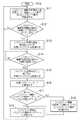
次に、ストレージシステム1におけるデータ移動量情報データベース作成処理について説明する。図11は、データ移動量情報データベース120の作成するための制御を行うデータ移動量情報データベース作成制御処理の具体的な処理手順を示したフローチャートである。(2) Data Movement Amount Information Database Creation Processing According to this Embodiment Next, data movement amount information database creation processing in the
チャネルアダプタ11は、初期時、図11に示すデータ移動量データベース作成処理手順RT1に従って、ホストシステム2から図12に示すデータ移動コマンド170が受信するのを待機モードで待ち受ける(S1)。 At the initial stage, the
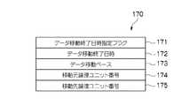
ここで、このデータ移動コマンド170は、図12に示すように、データ移動終了日時指定フラグ171、データ移動終了日時172、データ移動ペース173、移動元論理ユニット番号174、及び移動先論理ユニット番号から構成されている。 Here, as shown in FIG. 12, the
この場合、チャネルアダプタ11は、データ移動終了日時指定フラグがオンに設定されている場合には、後述のようにデータ移動終了日時にデータ移動が終了するようにデータ移動を開始させる一方、データ移動終了日時指定フラグがオフに設定されている場合には、データ移動コマンドが受信すると、その後データ移動を開始させる。 In this case, when the data movement end date / time designation flag is set to ON, the
なお、データ移動量データベース作成処理手順RT1においては、データ移動終了日時指定フラグがオフに設定されており、データ移動コマンド170が受信すると、その後データ移動を開始させるようになされている。 In the data movement amount database creation processing procedure RT1, the data movement end date / time designation flag is set to OFF, and when the
やがて、チャネルアダプタ11は、ホストシステム2からデータ移動コマンド170を受信すると(S1:YES)、データ移動ペース173、移動元論理ユニット番号174及び移動先論理ユニット番号175を、データ移動量情報121の移動元論理ユニット番号128及び移動先論理ユニット番号130として取得する。また、チャネルアダプタ11は、論理ユニット情報データベース110に基づいて、移動元論理ユニット番号128及び移動先論理ユニット番号130に対応する移動元ECCグループ番号129及び移動先ECCグループ番号131を取得する。さらに、チャネルアダプタ11は、データ移動ペーステーブル60に基づいて、データ移動ペース173に対応するデータ移動ペースコード124を取得する(S2)。 Eventually, when the
続いて、チャネルアダプタ11は、移動元論理ユニットから移動先論理ユニットへのデータ移動処理を開始し、内部タイマ50に基づいて、データ移動処理を開始したデータ移動開始日時を取得する。また、チャネルアダプタ11は、リードI/Oカウンタ51に基づいて、開始時における移動先ECCグループのリードI/Oカウント及び移動元論理ユニットのリードI/Oカウントを取得する。さらに、チャネルアダプタ11は、ライトI/Oカウンタ52に基づいて、開始時における移動元論理ユニットのライトI/Oカウントを取得する(S3)。 Subsequently, the
続いて、チャネルアダプタ11は、データ移動処理が終了するのを待機モードで待ち受ける(S4)。やがて、チャネルアダプタ11は、データ移動処理が終了すると(S4:YES)、内部タイマ50に基づいて、データ移動終了日時を取得する。また、チャネルアダプタ11は、リードI/Oカウンタ51に基づいて、終了時における移動先ECCグループのリードI/Oカウント及び移動元論理ユニットのリードI/Oカウントを取得する。さらに、チャネルアダプタ11は、ライトI/Oカウンタ52に基づいて、終了時における移動元論理ユニットのライトI/Oカウントを取得する。さらに、チャネルアダプタ11は、論理ユニット情報データベース110に基づいて、移動元論理ユニットのデータ容量114を取得する(S5)。 Subsequently, the
続いて、チャネルアダプタ11は、データ移動開始日時、データ移動終了日時、及び移動元論理ユニットのデータ容量114に基づいて、1時間あたりのデータ移動量を算出する。 Subsequently, the
具体的に、チャネルアダプタ11は、データ移動開始日時をTs、データ移動終了日時をTe、移動元論理ユニットのデータ容量114をDs、1時間あたりのデータ移動量をDmとすると、次式、 Specifically, the

に従って、1時間あたりのデータ移動量を算出し、データ移動量情報121のデータ移動量コード122として取得すると共に、データ移動量コード格納テーブル80に基づいて、1時間あたりのデータ移動量に対応する1時間あたりのデータ移動量コードをデータ移動量情報121のデータ移動量コード123として取得する。Accordingly, the data movement amount per hour is calculated and acquired as the data
また、チャネルアダプタ11は、データ移動開始日時、データ移動終了日時、開始時における移動元ECCグループのリードI/Oカウント、及び終了時における移動元ECCグループのリードI/Oカウントに基づいて、1時間あたりの移動元ECCグループのリードI/Oカウントを算出する。 Further, the
具体的に、チャネルアダプタ11は、データ移動開始日時Ts、データ移動終了日時Te、開始時における移動先ECCグループのリードI/OカウントCs、終了時における移動先ECCグループのリードI/OカウントCe、1時間あたりの移動先ECCグループのリードI/OカウントCmとすると、次式、 Specifically, the
に従って、1時間あたりの移動先ECCグループのリードI/Oカウントを算出し、I/Oカウントテーブル70に基づいて、1時間あたりの移動先ECCグループのリードI/Oカウントに対応する1時間あたりの移動先ECCグループのリードI/Oカウントコードをデータ移動量情報121の移動先ECCグループのリードI/Oカウントコード125として取得する。According to the above, the read I / O count of the destination ECC group per hour is calculated, and based on the I / O count table 70, per hour corresponding to the read I / O count of the destination ECC group per hour The read I / O count code of the transfer destination ECC group is acquired as the read I /
さらに、チャネルアダプタ11は、データ移動開始日時、データ移動終了日時、開始時における移動元論理ユニットのリードI/Oカウント、及び終了時における移動元論理ユニットのリードI/Oカウントに基づいて、上述の場合と同様の処理を施すことにより、1時間あたりの移動元論理ユニットのリードI/Oカウントを算出し、I/Oカウントテーブル70に基づいて、1時間あたりの移動元論理ユニットのリードI/Oカウントに対応する1時間あたりの移動元論理ユニットのリードI/Oカウントコードをデータ移動量情報121の移動元論理ユニットのリードI/Oカウントコード126として取得する。 Further, the
さらに、チャネルアダプタ11は、データ移動開始日時、データ移動終了日時、開始時における移動元論理ユニットのリードI/Oカウント、及び終了時における移動元論理ユニットのライトI/Oカウントに基づいて、上述の場合と同様の処理を施すことにより、1時間あたりの移動元論理ユニットのライトI/Oカウントを算出し、I/Oカウントテーブル70に基づいて、1時間あたりの移動元論理ユニットのライトI/Oカウントに対応する1時間あたりの移動元論理ユニットのライトI/Oカウントコードをデータ移動量情報121の移動元論理ユニットのライトI/Oカウントコード127として取得する(S6)。そして、チャネルアダプタ11は、内部タイマ50に基づいて、データ移動量情報作成終了日時を取得して、データ移動量情報121の作成を終了する。 Further, the
続いて、チャネルアダプタ11は、同一のデータ移動ペースコード124、移動元論理ユニット番号128、移動先論理ユニット番号130のデータ移動量情報121がデータ移動量情報データベース120に10以上格納されているか否かをチェックする(S7)。そして、チャネルアダプタ11は、当該データ移動量情報121がデータ移動量情報データベース120に10以上格納されている場合には(S7:YES)、データ移動量情報データベース120の同一のデータ移動ペースコード124、移動元論理ユニット番号128、移動先論理ユニット番号130のデータ移動量情報121のうち、データ移動量情報作成終了日時132のもっとも古いデータ移動量情報121を削除する(S8)。これに対して、チャネルアダプタ11は、当該データ移動量情報121がデータ移動量情報データベース120に10以上格納されていない場合には、当該データ移動量情報121をデータ移動量情報データベース120に格納する(S9)。 Subsequently, the
やがて、チャネルアダプタ11は、再びホストシステム2からデータ移動コマンド170を受信するのを待ち受ける待機モードに戻り(S1)、この後、同様の処理を繰り返す(S1〜S9→S1)。 Eventually, the
このようにしてストレージシステム1では、1時間あたりのデータ移動量122を作成するためにデータ移動量情報121を作成し、移動元論理ユニット128、移動先論理ユニット130及び移動ペースコード124ごとにデータ移動量情報121をデータ移動量情報データベース120に格納することができるようになされている。 In this way, in the
(3)本実施の形態によるI/Oカウント情報データベース作成処理
次に、ストレージシステム1におけるI/Oカウント情報データベース作成処理について説明する。図13は、I/Oカウント情報データベース140の作成するための制御を行うI/Oカウント情報データベース作成制御処理の具体的な処理手順を示したフローチャートである。(3) I / O Count Information Database Creation Processing According to this Embodiment Next, I / O count information database creation processing in the
ディスクアダプタ12は、初期時、図13に示すI/Oカウント情報データベース作成処理手順RT2に従って、内部タイマ50に基づいて、1時間ごとにこのI/Oカウント情報データベース作成処理手順RT2を開始して、I/Oカウント情報作成開始日時を取得し、日時コードに基づいて、I/Oカウント情報作成開始日時に対応する日時コードをI/Oカウント情報データベース141の日時コード147として取得する。また、ディスクアダプタ12は、対象とするすべての論理ユニットの論理ユニット番号を、I/Oカウント情報141の論理ユニット番号145として取得する。さらに、ディスクアダプタ12は、論理ユニット情報データベース110に基づいて、論理ユニット番号145に対応するECCグループ番号をI/Oカウント情報データベース141のECCグループ番号146として取得する(S11)。 Initially, the
続いて、ディスクアダプタ12は、I/Oカウント情報作成開始日時が1時間ごとの区切りになっているか否かをチェックする(S12)。そして、ディスクアダプタ12は、I/Oカウント情報作成開始日時が1時間ごとの区切りになっていない場合には(S12:NO)、内部タイマ50に基づいて、再びI/Oカウント情報作成開始日時を取得する(S1)。これに対して、ディスクアダプタ12は、対象とするすべての論理ユニットのI/Oカウント処理を開始し、リードI/Oカウンタ51に基づいて、開始時における論理ユニットに属するECCグループのリードI/Oカウント及び論理ユニットのリードI/Oカウントを取得する。また、ディスクアダプタ12は、ライトI/Oカウンタ52に基づいて、開始時における論理ユニットのライトI/Oカウントを取得する(S13)。 Subsequently, the
続いて、ディスクアダプタ12は、I/Oカウント情報作成開始日時から1時間が経過するのを待機モードで待ち受ける(S14)。やがて、ディスクアダプタ12は、I/Oカウント情報作成開始日時から1時間が経過すると(S14:YES)、対象とするすべての論理ユニットのI/Oカウント処理を終了し、内部タイマ50に基づいて、当該I/Oカウント処理を終了したI/Oカウント終了日時を取得する。また、ディスクアダプタ12は、リードI/Oカウンタ51に基づいて、終了時における論理ユニットに属するECCグループのリードI/Oカウント及び論理ユニットのリードI/Oカウントを取得する。さらに、ディスクアダプタ12は、ライトI/Oカウンタ52に基づいて、終了時における論理ユニットのライトI/Oカウントを取得する(S15)。 Subsequently, the
続いて、ディスクアダプタ12は、開始時におけるECCグループのリードI/Oカウント及び終了時におけるECCグループのリードI/Oカウントに基づいて、1時間あたりのECCグループのリードI/Oカウントを算出する。 Subsequently, the
具体的に、ディスクアダプタ11は、開始時におけるECCグループのリードI/OカウントをCs2、終了時におけるECCグループのリードI/OカウントをCe2、1時間あたりのECCグループのリードI/OカウントをCm2とすると、次式、Specifically, the
に従って、1時間あたりのECCグループのリードI/Oカウントを算出し、I/Oカウントテーブル70に基づいて、1時間あたりのECCグループのリードI/Oカウントに対応する1時間あたりのECCグループのリードI/OカウントコードをI/Oカウント情報141のECCグループのリードI/Oカウントコード142として取得する。The ECC group read I / O count per hour is calculated, and the ECC group read I / O count per hour corresponding to the ECC group read I / O count per hour is calculated based on the I / O count table 70. The read I / O count code is acquired as the read I /
また、ディスクアダプタ12は、開始時における論理ユニットのリードI/Oカウント及び終了時における論理ユニットのリードI/Oカウントに基づいて、上述の場合と同様の処理を施すことにより、1時間あたりの論理ユニットのリードI/Oカウントを算出し、I/Oカウントテーブル70に基づいて、1時間あたりの論理ユニットのリードI/Oカウントに対応する1時間あたりの論理ユニットのリードI/OカウントコードをI/Oカウント情報141の論理ユニットのリードI/Oカウントコード143として取得する。 Further, the
さらに、ディスクアダプタ12は、開始時における論理ユニットのライトI/Oカウント及び終了時における論理ユニットのライトI/Oカウントに基づいて、上述の場合と同様の処理を施すことにより、1時間あたりの論理ユニットのライトI/Oカウントを算出し、I/Oカウントテーブル70に基づいて、1時間あたりの論理ユニットのライトI/Oカウントに対応する1時間あたりの論理ユニットのライトI/OカウントコードをI/Oカウント情報141の論理ユニットのライトI/Oカウントコード144として取得する(S16)。そして、ディスクアダプタ12は、内部タイマ50に基づいて、I/Oカウント情報作成終了日時148を取得して、I/Oカウント情報141の作成を終了する。 Further, the
続いて、ディスクアダプタ12は、同一の論理ユニット番号145及び日時コード147のI/Oカウント情報141がI/Oカウント情報データベース140に10以上格納されているか否かをチェックする(S17)。 Subsequently, the
そして、ディスクアダプタ12は、当該I/Oカウント情報141がI/Oカウント情報データベース140に10以上格納されている場合には(S17:YES)、I/Oカウント情報データベース140の同一の論理ユニット番号145及び日時コード147のI/Oカウント情報141のうち、I/Oカウント情報作成終了日時148のもっとも古いI/Oカウント情報141を削除する(S18)。 When the I /
これに対して、ディスクアダプタ12は、当該I/Oカウント情報141がI/Oカウント情報データベース140に10以上格納されていない場合には、当該I/Oカウント情報141をI/Oカウント情報データベース140に格納する(S19)。 On the other hand, if the I /
やがて、ディスクアダプタ12は、再び内部カウンタ50に基づいて、I/Oカウンタ開始日時になるのを待ち受ける待機モードに戻り(S11)、この後、同様の処理を繰り返す(S11〜S19→S11)。 Eventually, the
このようにしてストレージシステム1では、1時間あたりのECCグループのリードI/Oカウントコード142、論理ユニットのリードI/Oカウントコード143及び論理ユニットのライトI/Oカウントコード144を作成するためにI/Oカウント情報141を作成し、対象とするすべての論理ユニットの論理ユニット番号145ごとにI/Oカウント情報141をデI/Oカウント情報データベース140に格納することができるようになされている。 In this way, the
(4)本実施の形態によるデータ移動開始日時情報データベース作成処理
次に、ストレージシステム1におけるデータ移動開始日時情報データベース作成処理について説明する。図14は、データ移動開始日時情報データベース150の作成するための制御を行うデータ移動開始日時情報データベース作成制御処理の具体的な処理手順を示したフローチャートである。(4) Data migration start date / time information database creation processing according to the present embodiment Next, data migration start date / time information database creation processing in the
チャネルアダプタ11は、初期時、図14に示すデータ移動開始日時情報データベース作成処理手順RT3に従って、ホストシステム2から図12に示すデータ移動コマンド170を受信するのを待機モードで待ち受ける(S21)。 Initially, the
なお、データ移動開始日時情報データベース作成処理手順RT3においては、データ移動終了日時指定フラグ171がオンに設定され、データ移動終了日時172が設定されている。 In the data movement start date / time information database creation processing procedure RT3, the data movement end date /
やがて、チャネルアダプタ11は、ホストシステム2からデータ移動コマンド170を受信すると(S21:YES)、処理番号152を取得すると共に、データ移動コマンド170の移動元論理ユニット番号174及び移動先論理ユニット番号175を、データ移動開始日時情報151の移動元論理ユニット番号153及び移動先論理ユニット番号154として取得する。また、チャネルアダプタ11は、論理ユニット情報データベース110に基づいて、移動元論理ユニットのデータ容量114を取得する(S22)。 Eventually, when the
続いて、チャネルアダプタ11は、日時コードテーブル90に基づいて、データ移動コマンド170のデータ移動終了日時172から24時間前まで1時間ごとに遡った日時に対応する日時コードを、データ移動開始日時情報151の時間帯別予想データ移動量情報155の時間帯コード160(時間帯コード1〜時間帯コード24)として取得する(S23)。 Subsequently, based on the date / time code table 90, the
ここで、チャネルアダプタ11は、データ移動開始日時情報151の時間帯別予想データ移動量情報155の時間帯コード160を取得すると、時間帯コード160ごとの1時間あたりの平均リードI/Oカウントコード及び平均リードI/Oカウントコードを算出する平均I/Oカウント算出処理を実行する。 Here, when the
図15は、時間帯コード160ごとの1時間あたりの平均リードI/Oカウントコード及び平均リードI/Oカウントコードを算出するための制御を行う平均I/Oカウント算出処理の具体的な処理手順を示したフローチャートである。 FIG. 15 shows a specific processing procedure of an average read I / O count code per hour for each
チャネルアダプタ11は、初期時、図15に示す平均I/Oカウント算出処理手順RT4に従って、データ移動開始日時情報151の移動元論理ユニット番号153及び時間帯コード160と同一の移動元論理ユニット番号145及び日時コード147のI/Oカウント情報141がI/Oカウント情報データベース140に格納されているか否かをチェックする(S41)。 Initially, the
そして、チャネルアダプタ11は、移動元論理ユニット番号153及び時間帯コード160と同一の移動元論理ユニット番号145及び日時コード147のI/Oカウント情報141がI/Oカウント情報データベース140に格納されていない場合には(S41:NO)、異常があったと判断して、この平均I/Oカウント算出処理手順RT4を終了する(S45)。 The
これに対して、チャネルアダプタ11は、移動元論理ユニット番号153及び時間帯コード160と同一の移動元論理ユニット番号145及び日時コード147のI/Oカウント情報141がI/Oカウント情報データベース140に格納されている場合には(S41:YES)、データ移動開始日時情報151の移動元論理ユニット番号153及び時間帯コード160と同一の移動元論理ユニット番号145及び日時コード147のすべてのI/Oカウント情報141からそれぞれ論理ユニットのリードI/Oカウント143及びライトI/Oカウント144を取得する(S43)。 On the other hand, in the
続いて、チャネルアダプタ11は、すべてのI/Oカウント情報141のそれぞれの論理ユニットのリードI/Oカウント143に基づいて、1時間あたりの平均リードI/Oカウントを算出する。 Subsequently, the
具体的に、チャネルアダプタ11は、I/Oカウント情報141のそれぞれの論理ユニットのリードI/Oカウント143をi(n)(1≦n≦10)、平均リードI/Oカウントをimとすると、次式、 Specifically, the
に従って、1時間あたりの平均リードI/Oカウントを算出し、I/Oカウントテーブル70に基づいて、1時間あたりの平均リードI/Oカウントに対応する平均リードI/Oカウントコードを、対応するデータ移動開始日時情報151の時間帯別予想データ移動量情報155の平均リードI/Oカウントコード162として取得する。The average read I / O count per hour is calculated, and the average read I / O count code corresponding to the average read I / O count per hour is determined based on the I / O count table 70. It is acquired as the average read I /
さらに、チャネルアダプタ11は、すべてのI/Oカウント情報141のそれぞれの論理ユニットのライトI/Oカウント144に基づいて、上述の場合と同様の処理を施すことにより、1時間あたりの平均ライトI/Oカウントを算出し、I/Oカウントテーブル70に基づいて、1時間あたりの平均ライトI/Oカウントに対応する平均ライトI/Oカウントコードを対応するデータ移動開始日時情報151の時間帯別予想データ移動量情報155の平均ライトI/Oカウントコード163として取得する(S43)。 Further, the
続いて、チャネルアダプタ11は、平均I/Oカウント算出処理手順RT4が終了すると(S44)、平均I/Oカウント算出処理が正常に終了したか否かをチェックする(S24)。 Subsequently, when the average I / O count calculation processing procedure RT4 ends (S44), the
そして、チャネルアダプタ11は、平均I/Oカウント算出処理が正常に終了していない場合には(S24:NO)、異常があったと判断し、ホストシステム2にエラー報告を行った後(S25)、このデータ移動開始日時情報データベース作成処理手順RT3を終了する(S33)。 Then, when the average I / O count calculation process is not normally completed (S24: NO), the
これに対して、チャネルアダプタ11は、平均リードI/Oカウント、平均ライトI/Oカウント算出処理が正常に終了した場合には(S24:YES)、時間帯コードごとの1時間あたりの平均データ移動量を算出する平均データ移動量算出処理を実行する。 In contrast, when the average read I / O count and average write I / O count calculation processing ends normally (S24: YES), the
ここで、図16は、時間帯コード160ごとの1時間あたりの平均データ移動量コードを算出するための制御を行う平均データ移動量算出処理の具体的な処理手順を示したフローチャートである。 Here, FIG. 16 is a flowchart showing a specific processing procedure of an average data movement amount calculation process for performing control for calculating an average data movement amount code per hour for each
チャネルアダプタ11は、初期時、図16に示す平均データ移動量算出処理手順RT5に従って、データ移動コマンド170のデータ移動ペース173に対応するデータ移動ペースコードを取得する(S51)。 At the initial time, the
続いて、チャネルアダプタ11は、当該データ移動ペースコード、並びにデータ移動開始日時情報151の移動元論理ユニット番号153、移動先論理ユニット番号154と同一のデータ移動ペースコード124、移動元論理ユニット番号128及び移動先論理ユニット番号130のデータ移動量情報121がデータ移動量情報データベース120に格納されているか否かをチェックする(S52)。 Subsequently, the
そして、チャネルアダプタ11は、データ移動ペースコード、並びにデータ移動開始日時情報151の移動元論理ユニット番号153、移動先論理ユニット番号154と同一のデータ移動ペースコード124、移動元論理ユニット番号128及び移動先論理ユニット番号130のデータ移動量情報121がデータ移動量情報データベース120に格納されていない場合には(S52:NO)、論理ユニット情報データベース110に基づいて、移動元論理ユニット番号153及び移動先論理ユニット番号154に対応する移動元ECCグループ番号及び移動先ECCグループ番号を取得する(S53)。 Then, the
続いて、チャネルアダプタ11は、当該移動元ECCグループ番号及び移動先ECCグループ番号と同一の移動元ECCグループ番号128及び移動先ECCグループ番号130のデータ移動量情報121がデータ移動量情報データベース120に格納されているか否かをチェックする(S54)。 Subsequently, the
そして、チャネルアダプタ11は、当該移動元ECCグループ番号及び移動先ECCグループ番号と同一の移動元ECCグループ番号128及び移動先ECCグループ番号130のデータ移動量情報121がデータ移動量情報データベース120に格納されていない場合には(S54:NO)、異常があったと判断して、この平均データ移動量算出処理手順RT5を終了する(S58)。 The
これに対して、チャネルアダプタ11は、当該移動元ECCグループ番号及び移動先ECCグループ番号と同一の移動元ECCグループ番号128及び移動先ECCグループ番号130のデータ移動量情報121がデータ移動量情報データベース120に格納されている場合には(S54:YES)、移動元ECCグループ番号及び移動先ECCグループ番号と同一の移動元ECCグループ番号128及び移動先ECCグループ番号130のデータ移動量情報121に、対応する時間帯別予想データ移動量情報155の平均リードI/Oカウントコード162及び平均ライトI/Oカウントコード163と同一のデータ移動量情報121がデータ移動量情報データベース120に格納されているか否かをチェックする(S55)。 In contrast, in the
また、チャネルアダプタ11は、同時に、データ移動ペースコード、並びにデータ移動開始日時情報151の移動元論理ユニット番号153、移動先論理ユニット番号154と同一のデータ移動ペースコード124、移動元論理ユニット番号128及び移動先論理ユニット番号130のデータ移動量情報121がデータ移動量情報データベース120に格納されている場合には(S52:YES)、データ移動ペースコード、並びにデータ移動開始日時情報151の移動元論理ユニット番号153、移動先論理ユニット番号154と同一のデータ移動ペースコード124、移動元論理ユニット番号128及び移動先論理ユニット番号130のデータ移動量情報121に、対応する時間帯別予想データ移動量情報155の平均リードI/Oカウントコード162及び平均ライトI/Oカウントコード163と同一のデータ移動量情報121がデータ移動量情報データベース120に格納されているか否かをチェックする(S55)。 Further, the
そして、チャネルアダプタ11は、対応する時間帯別予想データ移動量情報155の平均リードI/Oカウントコード162及び平均ライトI/Oカウントコード163と同一のデータ移動量情報121がデータ移動量情報データベース120に格納されていない場合には(S55:NO)、異常があったと判断して、この平均データ移動量算出処理手順RT5を終了する(S58)。 Then, the
これに対して、チャネルアダプタ11は、対応する時間帯別予想データ移動量情報155の平均リードI/Oカウントコード162及び平均ライトI/Oカウントコード163と同一のデータ移動量情報121がデータ移動量情報データベース120に格納されている場合には(S55:YES)、対応する時間帯別予想データ移動量情報155の平均リードI/Oカウントコード162及び平均ライトI/Oカウントコード163と同一のすべてのデータ移動量情報121からそれぞれデータ移動量122を取得する(S56)。 On the other hand, the
続いて、チャネルアダプタ11は、すべてのデータ移動量情報121のそれぞれのデータ移動量122に基づいて、1時間あたりの平均データ移動量を算出する。 Subsequently, the
具体的に、チャネルアダプタ11は、データ移動量情報121のそれぞれのデータ移動量122をd(n)(1≦n≦10)、1時間あたりの平均データ移動量をdmとすると、次式、 Specifically, the
に従って、1時間あたりの平均データ移動量を算出し、データ移動ペーステーブル60に基づいて、1時間あたりの平均データ移動量に対応する平均データ移動量コードを、対応するデータ移動開始日時情報151の時間帯別予想データ移動量情報155の平均データ移動量コード161として取得する(S57)。The average data movement amount per hour is calculated according to the data movement pace table 60, and the average data movement amount code corresponding to the average data movement amount per hour is obtained from the corresponding data movement start date /
続いて、チャネルアダプタ11は、平均データ移動量算出処理手順RT5が終了すると(S58)、平均データ移動量算出処理が正常に終了したか否かをチェックする(S26)。そして、チャネルアダプタ11は、平均データ移動量算出処理が正常に終了していない場合には(S26:NO)、異常があったと判断し、ホストシステム2にエラー報告を行った後(S25)、このデータ移動開始日時情報データベース作成処理手順RT3を終了する(S33)。 Subsequently, when the average data movement amount calculation processing procedure RT5 is completed (S58), the
これに対して、チャネルアダプタ11は、平均データ移動量算出処理が正常に終了した場合には(S26:YES)、各時間帯別予想データ移動量情報155の平均データ移動量161の積算値が移動元論理ユニットのデータ容量114に比して大きくなったか否かをチェックする(S27)。そして、チャネルアダプタ11は、平均データ移動量161の積算値が移動元論理ユニットのデータ容量に比して大きくなっていない場合には(S27:NO)、次に対応する時間帯別予想データ移動量情報155の時間帯コード160があるか否かをチェックする(S28)。 On the other hand, when the average data movement amount calculation process ends normally (S26: YES), the
そして、チャネルアダプタ11は、次に対応する時間帯別予想データ移動量情報155の時間帯コード160がない場合(S28:NO)、すなわち時間帯別予想データ移動量情報155の時間帯コード160が時間帯コード24まで使用されている場合には、異常があったと判断し、ホストシステム2にエラー報告を行った後(S29)、このデータ移動開始日時情報データベース作成処理手順RT3を終了する(S33)。 Then, when there is no
これに対して、チャネルアダプタ11は、次に対応する時間帯別予想データ移動量情報155の時間帯コード160がある場合(S28:YES)、すなわち時間帯別予想データ移動量情報155の時間帯コード160が時間帯コード24まで使用されていない場合には、次に対応する時間帯別予想データ移動量情報155の平均I/Oカウント算出処理手順RT4を実行する(RT4)。 On the other hand, when there is the
これに対して、チャネルアダプタ11は、平均データ移動量161の積算値が移動元論理ユニットのデータ容量114に比して大きくなった場合には(S27:YES)、このときの時間帯コード160をデータ移動開始日時情報151のデータ移動開始日時コード158として取得する(S30)。 On the other hand, when the integrated value of the average
続いて、チャネルアダプタ11は、日時コードテーブル90に基づいて、データ移動開始日時コード159に対応するデータ移動開始日時を取得し、当該データ移動開始日時よりも、内部タイマ50に基づいて計測された現在日時のほうが過去の日時となっているか否かをチェックする(S31)。 Subsequently, the
そして、チャネルアダプタ11は、データ移動開始日時よりも、内部タイマ50に基づいて計測された現在日時のほうが過去の日時となっていない場合には(S31:NO)、異常があったと判断し、ホストシステム2にエラー報告を行った後(S25)、このデータ移動開始日時情報データベース作成処理手順RT3を終了する(S33)。 When the current date and time measured based on the
これに対して、チャネルアダプタ11は、データ移動開始日時よりも、内部タイマ50に基づいて計測された現在日時のほうが過去の日時となっている場合には(S31:YES)、日時コードテーブル90に基づいて、データ移動開始日時コード159の1時間後の日時コードを更新時間帯コード156として取得すると共に、実データ移動量157を「0」として取得し、データ移動開始日時情報151の作成を終了する。 On the other hand, when the current date and time measured based on the
そして、チャネルアダプタ11は、当該データ移動開始日時情報151をデータ移動開始日時情報データベース150に格納し(S32)、この後、データ移動開始日時情報データベース作成処理手順RT3を終了する(S33)。 Then, the
このようにしてストレージシステム1では、データ移動コマンド170のデータ移動終了日時172から24時間前まで1時間ごとに遡った時間帯コード160における平均データ移動量コード161、平均リードI/Oカウントコード162及び平均ライトI/Oカウントコード163に基づいて、データ移動開始日時コード159を算出することができるようになされている In this way, in the
(4)本実施の形態によるデータ移動ペース制御処理
次に、ストレージシステム1におけるデータ移動ペース制御処理について説明する。図17は、データ移動処理時におけるデータ移動ペースの制御を行うデータ移動ペース制御処理の具体的な処理手順を示したフローチャートである。(4) Data Movement Pace Control Processing According to this Embodiment Next, data movement pace control processing in the
ディスクアダプタ12は、初期時、図17に示すデータ移動ペース制御処理手順RT6に従って、データ移動開始日時情報151におけるデータ移動開始日時コード159の日時が経過するのを待機モードで待ち受ける(S61)。やがて、ディスクアダプタ12は、データ移動開始日時コード159の日時が経過すると(SP61:YES)、移動元論理ユニットから移動先論理ユニットへのデータ移動処理を開始する(S62)。 In the initial stage, the
続いて、ディスクアダプタ12は、更新時間帯コード156の日時が経過するのを待機モードで待ち受ける(S63)。やがて、ディスクアダプタ12は、更新時間帯コード156の日時が経過すると(SP63:YES)、更新時間帯コード156の日時までの実際のデータ移動量を算出して、データ移動開始日時情報151における実データ移動量158として取得する(S64)。 Subsequently, the
続いて、ディスクアダプタ12は、予想データ移動量157及び実データ移動量158が同じとなっているか否かをチェックする(S65)。そして、ディスクアダプタ12は、予想データ移動量157及び実データ移動量158が同じとなっていない場合には(S65:NO)、予想データ移動量157と実データ移動量158との差分を、当該予想データ移動量157に上乗せし、データ移動量テーブル80に基づいて、この差分上乗せデータ移動量に対応する差分上乗せデータ移動量コードを取得する(S66)。 Subsequently, the
続いて、ディスクアダプタ12は、当該差分上乗せデータ移動量コード、データ移動開始日時情報151における移動元論理ユニット番号153及び移動先論理ユニット番号154、並びに更新時間帯コード156の時間帯別予想データ移動量情報155の平均リードI/Oカウント162及び平均ライトI/Oカウント163と同一のデータ移動量情報121がデータ移動量情報データベース120に格納されているか否かをチェックする(S67)。 Subsequently, the
そして、ディスクアダプタ12は、同一のデータ移動量情報121がデータ移動量情報データベース120に格納されている場合には(S67:YES)、データ移動量情報121のうち、データ移動ペースがもっとも大きいデータ移動ペースコードでデータ移動処理を続ける(S68)。 Then, when the same data
これに対して、ディスクアダプタ12は、同一のデータ移動量情報121がデータ移動量情報データベースに格納されていない場合(S67:NO)、又は、予想データ移動量157及び実データ移動量158が同じとなっている場合(S65:YES)には、データ移動コマンド170のデータ移動ペースペース173でデータ移動処理を続ける(S69)。 In contrast, in the
続いて、ディスクアダプタ12は、更新時間帯コード156から1時間後の日時コードである次の更新時間帯コードを更新時間帯コード156として取得する。また、ディスクアダプタ12は、次の更新時間帯コードと同一の時間帯別予想データ移動量情報155の予想データ量161を、更新時間帯コード156までの予想データ移動量157と積算して、次の更新時間帯コードの予想データ移動量を作成し、これを予想データ移動量157として取得する(S70)。 Subsequently, the
やがて、ディスクアダプタ12は、再び更新時間帯コード156の日時が経過するのを待ち受ける待機モードに戻り(S63)、この後、同様の処理を繰り返す(S63〜S70→S63)。 Eventually, the
(5)本実施の形態による動作及び効果
このように本実施の形態によるストレージシステム1では、データ移動コマンド170のデータ移動終了日時172から24時間前まで1時間ごとに遡った時間帯コード160ごとにおける平均リードI/Oカウント及び平均ライトI/Oカウントを算出し、当該平均リードI/Oカウント及び平均ライトI/Oカウントに基づいて、時間帯コード160ごとにおける予想データ移動量161を算出して、この予想データ移動量161に基づいて、データ移動開始日時コード159を算出する。(5) Operations and Effects According to this Embodiment As described above, in the
従って、このストレージシステム1では、ユーザがデータ移動終了日時を推測してデータ移動開始日時を設定することなく、データ移動終了日時を指定するだけで、当該データ移動終了日時にデータ移動を終了するようなデータ移動開始日時を設定することができる。また、このストレージシステム1では、当該データ移動終了日時にデータ移動を終了するようなデータ移動開始日時を設定するため、予備の記憶デバイスを用意することなく、記憶デバイスを効率的に使用することができる。 Therefore, in this
なお、このとき本実施の形態によるストレージシステム1では、平均データ移動量161の積算値が移動元論理ユニットのデータ容量114に比して大きくなった場合の時間帯コードをデータ移動開始日時情報151のデータ移動開始日時コード158として取得するようになされている。 At this time, in the
また、本実施の形態によるストレージシステム1では、データ移動開始日時コード159が経過したときに、データ移動コマンド170のデータ移動ペース173で、移動元論理ユニットから移動先論理ユニットにデータ移動を開始し、更新時間帯コード156が経過したときに、予想データ移動量157及び実データ移動量158が同じとなっているか否かをチェックし、同じとなっていない場合には、差分上乗せデータ移動量に基づいて、データ移動量情報121のうち、データ移動ペースがもっとも大きいデータ移動ペースコードに変更する。 Further, in the
従って、このストレージシステム1では、データ移動時における転送速度等の要因により、移動終了時間が前後するような場合についても、データ移動ペースを変更して、データ移動終了日時にデータ移動を終了することができる。 Therefore, in this
さらに、本実施の形態によるストレージシステム1では、記憶デバイス21に高価なディスクドライブを用い、記憶デバイス41に安価なディスクドライブを用いるようにしたことにより、当該データ移動終了日時にデータ移動を終了するようなデータ移動開始日時を設定するため、予備の高価な記憶デバイスを用意することなく、データライフサイクルマネージメントにも適応して、高価な記憶デバイスを一段と効率的に使用することができる。 Furthermore, in the
なお上述の実施の形態においては、一連の処理をそれぞれの機能を有するハードウェアにより実行させた場合について述べたが、本発明はこれに限らず、ソフトウェアにより実行させるようにしても良い。このとき、一連の処理をソフトウェアにより実行させる場合には、そのソフトウェアを構成するプログラムが専用のハードウェアに組み込まれているコンピュータに対して、各種プログラムをインストールすることで各種の機能を実行することが可能となり、例えば記録媒体からインストールされることができるようになされている。そしてこの記録媒体は、例えば、光ディスク、光磁気ディスク、半導体メモリ、磁気ディスク等の種々の記録媒体を含むことは言うまでもない。また、例えば、インターネット等のネットワークを介してダウンロードすることによって、各種プログラムをインストールするようにしても良い。 In the above-described embodiment, the case where a series of processing is executed by hardware having each function has been described. However, the present invention is not limited to this, and may be executed by software. At this time, when a series of processing is executed by software, various functions are executed by installing various programs on a computer in which the programs constituting the software are incorporated in dedicated hardware. For example, it can be installed from a recording medium. Needless to say, the recording medium includes various recording media such as an optical disk, a magneto-optical disk, a semiconductor memory, and a magnetic disk. Further, for example, various programs may be installed by downloading via a network such as the Internet.
本発明は、複数のディスクアレイ装置間において、データを移動させるストレージシステムのほか、この他種々のデータ移動を伴う機器に適用することができる。 The present invention can be applied not only to a storage system that moves data between a plurality of disk array devices, but also to other devices that involve various data movements.
1……ストレージシステム、2……ホストシステム、3……第1の記憶制御装置、4……第2の記憶制御装置、11、31……チャネルアダプタ、12、32……ディスクアダプタ、15……共有メモリ、20、40……記憶装置、21、41……記憶デバイス、110……論理ユニット情報データベース、120……データ移動量情報データベース、121……データ移動量情報、122……データ移動量、140……I/Oカウント情報データベース、141……I/Oカウント情報、142……ECCグループのリードI/Oカウント、144……論理ユニットのリードI/Oカウント、145……論理ユニットのライトI/Oカウント、150……データ移動開始日時情報データベース、151……データ移動開始日時情報、155……時間帯別予想データ移動量情報、160……時間帯コード、161……予想データ移動量、162……平均リードI/Oカウントコード、162……平均ライトI/Oカウントコード、159……データ移動開始日時コード、170……データ移動コマンド、172……データ移動終了日時、173……データ移動ペースDESCRIPTION OF
Claims (13)
Translated fromJapanese外部操作によりデータ移動終了日時の指定があったときに、前記データ移動終了日時から所定時間ごとに遡った時間帯ごとにおける前記移動元ボリュームへのアクセス頻度を算出するアクセス頻度算出部と、
前記アクセス頻度算出部により算出されたアクセス頻度に基づいて、前記時間帯ごとにおける予想データ移動量を算出する予想データ移動量算出部と、
前記予想データ移動量算出部により算出された予想データ移動量に基づいて、データ移動開始日時を算出するデータ移動開始日時算出部と
を備えることを特徴とするディスクアレイ装置。A disk array device having a migration source volume as a migration source when moving data, and moving the data from the migration source volume to another migration destination volume as a migration destination,
An access frequency calculation unit that calculates an access frequency to the migration source volume in each time zone that is traced every predetermined time from the data movement end date and time when the data movement end date and time is designated by an external operation;
Based on the access frequency calculated by the access frequency calculation unit, an expected data movement amount calculation unit that calculates an expected data movement amount for each time period;
A disk array apparatus comprising: a data movement start date / time calculation unit that calculates a data movement start date / time based on the predicted data movement amount calculated by the predicted data movement amount calculation unit.
前記時間帯ごとにおける予想データ移動量の積算値が前記移動元のボリュームの容量に比して大きくなったときの時間帯の始めの時間をデータ移動開始日時として算出する
ことを特徴とする請求項1に記載のディスクアレイ装置。The data movement start date and time calculation unit
The start time of the time zone when the integrated value of the predicted data movement amount for each time zone becomes larger than the capacity of the migration source volume is calculated as the data movement start date and time. 2. The disk array device according to 1.
を備え、
前記データ移動部は、
外部操作によりデータ移動ペースの指定があったときに、データ移動ペースに基づいて前記移動元ボリュームから前記他の移動先ボリュームにデータを移動させ、所定の時間帯ごとに、前記時間帯までの予想データ移動量の積算値と、前記時間帯までの実際のデータ移動量を比較して、前記予想データ移動量の積算値と前記時間帯までの実際のデータ移動量との差分に応じて前記データ移動ペースを変更する
ことを特徴とする請求項1に記載のディスクアレイ装置。A data migration unit that migrates data from the migration source volume to the other migration destination volume when the data migration start date and time calculated by the data migration start date and time calculation unit has passed,
The data moving unit is
When the data movement pace is specified by an external operation, the data is moved from the movement source volume to the other movement destination volume based on the data movement pace, and the prediction to the time period is performed every predetermined time period. The integrated value of the data movement amount is compared with the actual data movement amount up to the time period, and the data according to the difference between the integrated value of the predicted data movement amount and the actual data movement amount up to the time period The disk array device according to claim 1, wherein the moving pace is changed.
前記予想データ移動量の積算値と前記時間帯までの実際のデータ移動量とが同一である場合には、前記外部操作により指定された前記データ移動ペースのまま、前記移動元ボリュームから前記他の移動先ボリュームにデータを移動させる
ことを特徴とする請求項3に記載のディスクアレイ装置。The data moving unit is
If the integrated value of the predicted data movement amount and the actual data movement amount up to the time period are the same, the data movement pace designated by the external operation is kept as it is from the movement source volume. The disk array device according to claim 3, wherein the data is moved to the destination volume.
高価なハードディスクドライブに記憶され、
前記他の移動先ボリュームは、
安価なハードディスクドライブに記憶される
ことを特徴とする請求項1に記載のディスクアレイ装置。The migration source volume is
Stored in an expensive hard disk drive,
The other destination volume is
The disk array device according to claim 1, wherein the disk array device is stored in an inexpensive hard disk drive.
外部操作によりデータ移動終了日時の指定があったときに、前記データ移動終了日時から所定時間ごとに遡った時間帯ごとにおける前記移動元ボリュームへのアクセス頻度を算出する第1のステップと、
前記第1のステップにおいて算出したアクセス頻度に基づいて、前記時間帯ごとにおける予想データ移動量を算出する第2のステップと、
前記第2のステップにおいて算出した予想データ移動量に基づいて、データ移動開始日時を算出する第3のステップと
を備えることを特徴とするディスクアレイ装置のデータ移動方法。A data movement method for a disk array device having a migration source volume as a migration source when moving data, and moving the data from the migration source volume to another migration destination volume as a migration destination,
A first step of calculating an access frequency to the migration source volume in a time zone that is traced every predetermined time from the data migration end date and time when the data migration end date and time is designated by an external operation;
Based on the access frequency calculated in the first step, a second step of calculating an expected data movement amount for each time period;
And a third step of calculating a data movement start date and time based on the predicted data movement amount calculated in the second step.
前記時間帯ごとにおける予想データ移動量の積算値が前記移動元のボリュームの容量に比して大きくなったときの時間帯の始めの時間をデータ移動開始日時として算出する
ことを特徴とする請求項6に記載のディスクアレイ装置のデータ移動方法。In the third step,
The start time of the time zone when the integrated value of the predicted data movement amount for each time zone becomes larger than the capacity of the migration source volume is calculated as the data movement start date and time. 7. A data movement method for the disk array device according to 6.
を備え、
前記第4のステップでは、
外部操作によりデータ移動ペースの指定があったときに、データ移動ペースに基づいて前記移動元ボリュームから前記他の移動先ボリュームにデータを移動させ、所定の時間帯ごとに、前記時間帯までの予想データ移動量の積算値と、前記時間帯までの実際のデータ移動量を比較して、前記予想データ移動量の積算値と前記時間帯までの実際のデータ移動量との差分に応じて前記データ移動ペースを変更する
ことを特徴とする請求項6に記載のディスクアレイ装置のデータ移動方法。A fourth step of moving data from the migration source volume to the other migration destination volume when the data migration start date and time calculated in the third step has elapsed,
In the fourth step,
When the data movement pace is specified by an external operation, the data is moved from the movement source volume to the other movement destination volume based on the data movement pace, and the prediction to the time period is performed every predetermined time period. The integrated value of the data movement amount is compared with the actual data movement amount up to the time period, and the data according to the difference between the integrated value of the predicted data movement amount and the actual data movement amount up to the time period The data movement method of the disk array device according to claim 6, wherein the movement pace is changed.
前記予想データ移動量の積算値と前記時間帯までの実際のデータ移動量とが同一である場合には、前記外部操作により指定された前記データ移動ペースのまま、前記移動元ボリュームから前記他の移動先ボリュームにデータを移動させる
ことを特徴とする請求項9に記載のディスクアレイ装置のデータ移動方法。In the fourth step,
If the integrated value of the predicted data movement amount and the actual data movement amount up to the time period are the same, the data movement pace designated by the external operation is kept as it is from the movement source volume. The data migration method of the disk array device according to claim 9, wherein data is migrated to a migration destination volume.
外部操作によりデータ移動終了日時の指定があったときに、前記データ移動終了日時から所定時間ごとに遡った時間帯ごとにおける前記移動元ボリュームへのアクセス頻度を算出する第1のステップと、
前記第1のステップにおいて算出したアクセス頻度に基づいて、前記時間帯ごとにおける予想データ移動量を算出する第2のステップと、
前記第2のステップにおいて算出した予想データ移動量に基づいて、データ移動開始日時を算出する第3のステップと
を実行させることを特徴とするプログラム。For a disk array device that has a migration source volume as a migration source when moving data and moves the data from the migration source volume to another migration destination volume as a migration destination,
A first step of calculating an access frequency to the migration source volume in a time zone that is traced every predetermined time from the data migration end date and time when the data migration end date and time is designated by an external operation;
Based on the access frequency calculated in the first step, a second step of calculating an expected data movement amount for each time period;
And a third step of calculating a data movement start date and time based on the predicted data movement amount calculated in the second step.
前記時間帯ごとにおける予想データ移動量の積算値が前記移動元のボリュームの容量に比して大きくなったときの時間帯の始めの時間をデータ移動開始日時として算出する
ことを特徴とする請求項10に記載のプログラム。In the third step,
The start time of the time zone when the integrated value of the predicted data movement amount for each time zone becomes larger than the capacity of the migration source volume is calculated as the data movement start date and time. 10. The program according to 10.
を備え、
前記第4のステップでは、
外部操作によりデータ移動ペースの指定があったときに、データ移動ペースに基づいて前記移動元ボリュームから前記他の移動先ボリュームにデータを移動させ、所定の時間帯ごとに、前記時間帯までの予想データ移動量の積算値と、前記時間帯までの実際のデータ移動量を比較して、前記予想データ移動量の積算値と前記時間帯までの実際のデータ移動量との差分に応じて前記データ移動ペースを変更する
ことを特徴とする請求項10に記載のプログラム。A fourth step of moving data from the migration source volume to the other migration destination volume when the data migration start date and time calculated in the third step has elapsed,
In the fourth step,
When the data movement pace is specified by an external operation, the data is moved from the movement source volume to the other movement destination volume based on the data movement pace, and the prediction to the time period is performed every predetermined time period. The integrated value of the data movement amount is compared with the actual data movement amount up to the time period, and the data according to the difference between the integrated value of the predicted data movement amount and the actual data movement amount up to the time period The program according to claim 10, wherein the moving pace is changed.
前記予想データ移動量の積算値と前記時間帯までの実際のデータ移動量とが同一である場合には、前記外部操作により指定された前記データ移動ペースのまま、前記移動元ボリュームから前記他の移動先ボリュームにデータを移動させる
ことを特徴とする請求項12に記載のプログラム。
In the fourth step,
If the integrated value of the predicted data movement amount and the actual data movement amount up to the time period are the same, the data movement pace designated by the external operation is kept as it is from the movement source volume. The program according to claim 12, wherein the data is moved to the destination volume.
Priority Applications (2)
| Application Number | Priority Date | Filing Date | Title |
|---|---|---|---|
| JP2005262318AJP2007072988A (en) | 2005-09-09 | 2005-09-09 | Disk array device, data movement method, and program |
| US11/328,286US7594076B2 (en) | 2005-09-09 | 2006-01-10 | Disk array apparatus, data migration method, and storage medium |
Applications Claiming Priority (1)
| Application Number | Priority Date | Filing Date | Title |
|---|---|---|---|
| JP2005262318AJP2007072988A (en) | 2005-09-09 | 2005-09-09 | Disk array device, data movement method, and program |
Publications (1)
| Publication Number | Publication Date |
|---|---|
| JP2007072988Atrue JP2007072988A (en) | 2007-03-22 |
Family
ID=37856646
Family Applications (1)
| Application Number | Title | Priority Date | Filing Date |
|---|---|---|---|
| JP2005262318APendingJP2007072988A (en) | 2005-09-09 | 2005-09-09 | Disk array device, data movement method, and program |
Country Status (2)
| Country | Link |
|---|---|
| US (1) | US7594076B2 (en) |
| JP (1) | JP2007072988A (en) |
Cited By (3)
| Publication number | Priority date | Publication date | Assignee | Title |
|---|---|---|---|---|
| WO2014147816A1 (en)* | 2013-03-22 | 2014-09-25 | 株式会社 日立製作所 | Storage device and storage area verification method |
| WO2014167716A1 (en)* | 2013-04-12 | 2014-10-16 | 株式会社日立製作所 | Computer system management system and management method |
| WO2018131133A1 (en)* | 2017-01-13 | 2018-07-19 | 株式会社日立製作所 | Data migration system and data migration control method |
Families Citing this family (20)
| Publication number | Priority date | Publication date | Assignee | Title |
|---|---|---|---|---|
| US8452929B2 (en)* | 2005-04-21 | 2013-05-28 | Violin Memory Inc. | Method and system for storage of data in non-volatile media |
| US9286198B2 (en) | 2005-04-21 | 2016-03-15 | Violin Memory | Method and system for storage of data in non-volatile media |
| US9384818B2 (en) | 2005-04-21 | 2016-07-05 | Violin Memory | Memory power management |
| US8200887B2 (en) | 2007-03-29 | 2012-06-12 | Violin Memory, Inc. | Memory management system and method |
| US8028186B2 (en) | 2006-10-23 | 2011-09-27 | Violin Memory, Inc. | Skew management in an interconnection system |
| JP4814119B2 (en) | 2007-02-16 | 2011-11-16 | 株式会社日立製作所 | Computer system, storage management server, and data migration method |
| US11010076B2 (en) | 2007-03-29 | 2021-05-18 | Violin Systems Llc | Memory system with multiple striping of raid groups and method for performing the same |
| US9632870B2 (en) | 2007-03-29 | 2017-04-25 | Violin Memory, Inc. | Memory system with multiple striping of raid groups and method for performing the same |
| US8819363B2 (en)* | 2008-02-12 | 2014-08-26 | Fujitsu Limited | Data copying method |
| US7890454B2 (en)* | 2008-05-08 | 2011-02-15 | International Business Machines Corporation | Method and system for data disaggregation |
| US20090300283A1 (en)* | 2008-05-29 | 2009-12-03 | Yutaka Kudo | Method and apparatus for dissolving hot spots in storage systems |
| CN102576330B (en) | 2009-06-12 | 2015-01-28 | 提琴存储器公司 | Storage system with persistent garbage collection mechanism |
| US9672150B2 (en) | 2010-05-26 | 2017-06-06 | Hewlett Packard Enterprise Development Lp | Migrating write information in a write cache of a storage system |
| US8521693B2 (en) | 2010-10-26 | 2013-08-27 | Hitachi, Ltd. | Storage system and its operation method |
| WO2013042163A1 (en)* | 2011-09-21 | 2013-03-28 | Hitachi, Ltd. | Storage system and data migration processing control method |
| JP5782962B2 (en)* | 2011-09-27 | 2015-09-24 | 富士通株式会社 | RAID group control device |
| US8909734B2 (en)* | 2012-02-07 | 2014-12-09 | International Business Machines Corporation | Migrating data between networked computing environments |
| US9798627B2 (en)* | 2012-05-25 | 2017-10-24 | Veritas Technologies Llc | Backup image duplication |
| US9436724B2 (en)* | 2013-10-21 | 2016-09-06 | Sap Se | Migrating data in tables in a database |
| US10650015B2 (en)* | 2015-12-10 | 2020-05-12 | Sap Se | Dynamic migration of user interface application |
Family Cites Families (4)
| Publication number | Priority date | Publication date | Assignee | Title |
|---|---|---|---|---|
| EP1061449A4 (en)* | 1998-02-04 | 2005-12-21 | Hitachi Ltd | METHOD OF MANAGING ANEMATORY DISK, DISC STRUCTURE AND MEMORY |
| JP2003140836A (en) | 2001-10-30 | 2003-05-16 | Hitachi Ltd | Storage system management method, storage system management program, storage medium, and storage system |
| US20040194055A1 (en)* | 2003-03-24 | 2004-09-30 | International Business Machines Corporation | Method and program product for costing and planning the re-hosting of computer-based applications |
| TWI254854B (en)* | 2004-11-19 | 2006-05-11 | Via Tech Inc | Method and related apparatus for data migration of disk arrays |
- 2005
- 2005-09-09JPJP2005262318Apatent/JP2007072988A/enactivePending
- 2006
- 2006-01-10USUS11/328,286patent/US7594076B2/ennot_activeExpired - Fee Related
Cited By (5)
| Publication number | Priority date | Publication date | Assignee | Title |
|---|---|---|---|---|
| WO2014147816A1 (en)* | 2013-03-22 | 2014-09-25 | 株式会社 日立製作所 | Storage device and storage area verification method |
| US9459973B2 (en) | 2013-03-22 | 2016-10-04 | Hitachi, Ltd. | Storage subsystem, and method for verifying storage area |
| WO2014167716A1 (en)* | 2013-04-12 | 2014-10-16 | 株式会社日立製作所 | Computer system management system and management method |
| US9442765B2 (en) | 2013-04-12 | 2016-09-13 | Hitachi, Ltd. | Identifying shared physical storage resources having possibility to be simultaneously used by two jobs when reaching a high load |
| WO2018131133A1 (en)* | 2017-01-13 | 2018-07-19 | 株式会社日立製作所 | Data migration system and data migration control method |
Also Published As
| Publication number | Publication date |
|---|---|
| US7594076B2 (en) | 2009-09-22 |
| US20070061513A1 (en) | 2007-03-15 |
Similar Documents
| Publication | Publication Date | Title |
|---|---|---|
| JP2007072988A (en) | Disk array device, data movement method, and program | |
| JP4942446B2 (en) | Storage apparatus and control method thereof | |
| US7469315B2 (en) | Storage controller, and method of controlling storage controller to improve the reliability of the storage controller | |
| JP3541744B2 (en) | Storage subsystem and control method thereof | |
| US7581061B2 (en) | Data migration using temporary volume to migrate high priority data to high performance storage and lower priority data to lower performance storage | |
| US9207874B2 (en) | Synchronous extent migration protocol for paired storage | |
| JP4144727B2 (en) | Information processing system, storage area providing method, and data retention management device | |
| JP4920979B2 (en) | Storage apparatus and control method thereof | |
| EP1873624A2 (en) | Method and apparatus for migrating data between storage volumes | |
| US20090276565A1 (en) | Storage control apparatus, data management system and data management method | |
| EP1434125A2 (en) | Raid apparatus and logical device expansion method thereof | |
| EP1768014A1 (en) | Storage control apparatus, data management system and data management method | |
| CN103329106A (en) | Detection and handling of ALUA preferences and state transitions by host | |
| EP1868074A2 (en) | Storage system and storage control device | |
| JP2006072789A (en) | Storage system and storage system data management device | |
| JP2008276626A (en) | Storage control device and control method of storage control device | |
| CN101149667A (en) | Disk array system, storage system and storage system migration method | |
| JPWO2008136075A1 (en) | Storage management program, storage management device, and storage management method | |
| CN102334092A (en) | Storage system and its control method and program | |
| KR20030091664A (en) | Storage system and storage subsystem | |
| CN100401296C (en) | Method and system for configuring information storage and retrieval system | |
| JP2005115600A (en) | Information processing apparatus and method | |
| JP5595334B2 (en) | Time budgeting for non-data transmission in drive units | |
| US7337269B2 (en) | Method of managing a data storage array, and a computer system including a raid controller | |
| JP6019940B2 (en) | Information processing apparatus, copy control program, and copy control method |