JP2007070028A - Image forming device - Google Patents
Image forming deviceDownload PDFInfo
- Publication number
- JP2007070028A JP2007070028AJP2005257937AJP2005257937AJP2007070028AJP 2007070028 AJP2007070028 AJP 2007070028AJP 2005257937 AJP2005257937 AJP 2005257937AJP 2005257937 AJP2005257937 AJP 2005257937AJP 2007070028 AJP2007070028 AJP 2007070028A
- Authority
- JP
- Japan
- Prior art keywords
- recording medium
- printing
- image forming
- defective portion
- label
- Prior art date
- Legal status (The legal status is an assumption and is not a legal conclusion. Google has not performed a legal analysis and makes no representation as to the accuracy of the status listed.)
- Granted
Links
- 238000001514detection methodMethods0.000claimsabstractdescription44
- 230000002950deficientEffects0.000claimsdescription34
- 238000011144upstream manufacturingMethods0.000claimsdescription6
- 230000015572biosynthetic processEffects0.000claimsdescription5
- 238000005520cutting processMethods0.000abstractdescription7
- 229920000915polyvinyl chloridePolymers0.000description7
- 239000004800polyvinyl chlorideSubstances0.000description7
- 238000010586diagramMethods0.000description6
- 238000000034methodMethods0.000description4
- 239000000853adhesiveSubstances0.000description2
- 230000001070adhesive effectEffects0.000description2
- 239000000463materialSubstances0.000description2
- 239000002699waste materialSubstances0.000description2
- 230000005856abnormalityEffects0.000description1
- 239000003086colorantSubstances0.000description1
- 230000007423decreaseEffects0.000description1
- 230000002093peripheral effectEffects0.000description1
Images


Landscapes
- Printers Characterized By Their Purpose (AREA)
- Handling Of Sheets (AREA)
- Controlling Sheets Or Webs (AREA)
- Controlling Rewinding, Feeding, Winding, Or Abnormalities Of Webs (AREA)
Abstract
Description
Translated fromJapanese本発明は、長尺状の記録媒体を搬送しながらこの記録媒体に画像を形成する画像形成装置に関する。 The present invention relates to an image forming apparatus for forming an image on a recording medium while conveying a long recording medium.
記録媒体(印刷媒体)とインクリボンを介してプラテンローラの外周面にサーマルヘッド(印字ヘッド)を圧接させて記録媒体に画像を形成する(印字する)熱転写方式のプリンタ(画像形成装置)が知られている。この熱転写方式のプリンタで使用される記録媒体としては、PVCチューブ、熱収縮チューブ、4mmIDストリップ、ラベルテープなどが挙げられる。これら各種の記録媒体はそれぞれ専用のカセットに収容された状態で画像形成装置の本体に装着される。 Known is a thermal transfer type printer (image forming apparatus) that forms (prints) an image on a recording medium by pressing a thermal head (printing head) on the outer peripheral surface of the platen roller via a recording medium (printing medium) and an ink ribbon. It has been. Examples of the recording medium used in this thermal transfer type printer include a PVC tube, a heat shrinkable tube, a 4 mm ID strip, and a label tape. These various recording media are mounted on the main body of the image forming apparatus in a state of being stored in dedicated cassettes.
上記のラベルテープは、剥離紙(セパレータとも呼ばれる)と、粘着材が塗布されたラベルとで構成されており、ラベルを剥離紙に張り付けた状態で長尺状のままカセット内に巻かれている。ラベルに画像形成する(印刷する)際には、カセットに収容された長尺のラベルテープを一端から引き出して搬送しながら各ラベルに画像形成し、続いて、剥離紙を所定の長さに切断する。ユーザーは、剥離紙からラベルを剥がして印刷済のラベルのみを使用することになる(特許文献1参照)。
上記のようにカセットに収容された長尺のラベルテープを一端から引き出して搬送する搬送過程では、ラベルテープは搬送ローラ等で加圧されながら搬送される。この場合、ラベルテープのうち搬送ローラ等で加圧される直前の部分(搬送ローラよりもやや搬送搬送方向上流側の部分)において剥離紙とラベルにずれが発生することがあり、さらに、このずれが徐々に凸状に大きくなって凸が進行していくことがある。このように凸が進行した場合、ラベルが折れることがある。折れたラベルに画像形成しても、このラベルは使用できないので、無駄な画像形成をすることとなる。 In the transport process in which the long label tape accommodated in the cassette is pulled out from one end and transported as described above, the label tape is transported while being pressurized by a transport roller or the like. In this case, there may be a deviation between the release paper and the label in the portion of the label tape immediately before being pressed by the conveyance roller (the portion slightly upstream of the conveyance roller in the conveyance and conveyance direction). May gradually become convex and the convexity may advance. In this way, when the projection proceeds, the label may break. Even if an image is formed on a broken label, this label cannot be used, so that wasteful image formation is performed.
本発明は、上記事情に鑑み、無駄な画像形成(無駄印刷)を防止した画像形成装置を提供することを目的とする。 In view of the above circumstances, an object of the present invention is to provide an image forming apparatus that prevents useless image formation (useless printing).
上記目的を達成するための本発明の画像形成装置は、長尺状の記録媒体を搬送しながらこの記録媒体に画像を形成する画像形成装置において、
(1)搬送中の記録媒体の不具合部分を検出する検出手段を備えたことを特徴とするものである。An image forming apparatus of the present invention for achieving the above object is an image forming apparatus for forming an image on a recording medium while conveying a long recording medium.
(1) The present invention is characterized in that a detection means for detecting a defective portion of the recording medium being conveyed is provided.
ここで、
(2)前記検出手段は、長尺状の剥離紙と、この剥離紙に貼り付けられたラベルとからなる記録媒体の前記ラベルの一部が剥がれた不具合部分を検出するものであってもよい。here,
(2) The detection means may detect a defective portion in which a part of the label of a recording medium including a long release paper and a label attached to the release paper is peeled off. .
また、
(3)前記検出手段によって検出された不具合部分を除去する除去手段を備えてもよい。Also,
(3) You may provide the removal means which removes the malfunctioning part detected by the said detection means.
さらに、
(4)前記除去手段は、前記不具合部分を切断して除去するカッタであってもよい。further,
(4) The removing unit may be a cutter that cuts and removes the defective portion.
さらにまた、
(5)前記除去手段よりも搬送方向上流側に配置された、記録媒体を挟持して搬送する搬送手段を備え、
(6)前記検出手段は、前記搬送手段よりも前記搬送方向上流側に配置されたものであり、
(7)前記検出手段が前記不具合部分を検出したときは、前記搬送手段の挟持を解除して前記不具合部分を前記除去手段まで搬送させるように構成してもよい。Furthermore,
(5) provided with a conveying unit that is disposed on the upstream side in the conveying direction with respect to the removing unit and conveys the recording medium in a sandwiched manner;
(6) The detection means is arranged on the upstream side in the transport direction with respect to the transport means,
(7) When the detection means detects the defective portion, the holding means may be released to convey the defective portion to the removal means.
さらにまた、
(8)前記検出手段は、記録媒体の有無も検出するものであってもよい。Furthermore,
(8) The detection means may also detect the presence or absence of a recording medium.
さらにまた、
(9)記録媒体の種類を検知する種類検知手段を備え、
(10)前記検出手段は、記録媒体との距離に対応する電圧に基づいて前記不具合部分又は記録媒体の有無を検出するものであり、且つ、前記種類検知手段で検知された記録媒体の種類に基づいて検出結果を変更するものであってもよい。Furthermore,
(9) Provided with a type detecting means for detecting the type of the recording medium,
(10) The detection means detects the presence or absence of the defective portion or the recording medium based on a voltage corresponding to a distance from the recording medium, and determines the type of the recording medium detected by the type detection means. The detection result may be changed based on this.
本発明によれば、検出手段によって記録媒体の不具合部分が検出されるので、この不具合部分には画像が形成されないようにできる。このため、記録媒体には画像が無駄に形成されることはなく、無駄な画像形成(無駄印刷)を防止できる。 According to the present invention, since the defective portion of the recording medium is detected by the detecting means, it is possible to prevent an image from being formed on the defective portion. For this reason, an image is not formed wastefully on the recording medium, and wasteful image formation (waste printing) can be prevented.
本発明は、熱転写式のラベル印刷機に実現された。 The present invention has been realized in a thermal transfer type label printer.
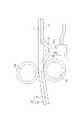
図1と図2を参照して、本発明の画像形成装置の一例である熱転写式のラベル印刷機について説明する。 With reference to FIGS. 1 and 2, a thermal transfer type label printing machine as an example of the image forming apparatus of the present invention will be described.
図1は、熱転写式のラベル印刷機の概略構成を示す斜視図である。図2は、記録媒体の種類を検知する種類検知手段の一例を示す模式図である。 FIG. 1 is a perspective view showing a schematic configuration of a thermal transfer type label printing machine. FIG. 2 is a schematic diagram illustrating an example of a type detection unit that detects the type of a recording medium.
ラベル印刷機10は可搬式のものであり、印字したい文字や記号を入力するキーボード12が設けられておる。キーボード12から入力された文字や記号は表示部14に表示される。ラベル印刷機10では、ラベル、熱収縮チューブ、IDストリップ、PVCチューブなどの記録媒体(被印字物)Tに画像が形成される。 The
ラベルテープは、厚さは薄くて一定のものであり、幅寸法は6、9、12、18、25mmなどである。また、その色としては、白と黄色の2種類が用意されている。ラベル印刷機10では、複数種類のラベルテープに印字する必要があり、各種類毎にロール状に巻回して媒体カセット16に格納(収容)されている。 The label tape has a thin and constant thickness, and width dimensions are 6, 9, 12, 18, 25 mm, and the like. In addition, two types of colors, white and yellow, are prepared. The
熱収縮チューブやPVCチューブは、チューブを形成する素材の厚みが比較的薄いので扁平に押しつぶしロール状に巻回してラベルテープと同じく媒体カセット16に納入される。なお、熱収縮チューブやPVCチューブには、その直径が互いに相違する複数種類のものがあり、直径が相違するので扁平に押し潰した場合、幅寸法の相違する帯状の形状になってカセット内に格納される。 Since the thickness of the material forming the tube is relatively thin, the heat-shrinkable tube or the PVC tube is flattened and wound into a roll and delivered to the
4mmIDストリップは、電線等に予め取り付けられたストリップホルダーに差し込まれるものであり、厚みが比較的厚く(1mm程度)、かつ幅寸法が4、6、9、12、18、25mmのものが用意されている。この4mmIDストリップも上記ラベル、熱収縮チューブ、塩ビチューブと同じくロール状に巻回されて媒体カセット16内に格納される。このようにほとんどの被印字物Tの種類を取り替える際には媒体カセット16を交換することになる。 The 4 mm ID strip is inserted into a strip holder previously attached to an electric wire or the like, and the thickness is relatively thick (about 1 mm) and the width dimension is 4, 6, 9, 12, 18, 25 mm. ing. This 4 mm ID strip is also wound into a roll like the label, heat shrinkable tube, and polyvinyl chloride tube, and stored in the
上記のようにラベル印刷機10では複数種類の記録媒体Tに印刷できるので、媒体カセット16に収容されている記録媒体の種類を検知する種類検知器(プッシュスイッチセンサ)20が備えられている。媒体カセット16の底部には、記録媒体Tの種類に応じた凹部(種類によって異なる数の凹部)が形成されている。種類検知器20には、凹部に嵌まり込む複数の棒状のプッシュスイッチ22が備えられている。媒体カセット16がラベル印刷機10の所定位置に装着された場合、記録媒体Tの種類に応じた凹部に複数のプッシュスイッチ22が選択的に嵌り込み、これによって発生する電気信号がラベル印刷機10のCPU(図示せず)に送られて記録媒体Tの種類が検知される(判別される)。 Since the
記録媒体Tに印刷するに際しては、先ず、媒体カセット16をラベル印刷機10に装着する(セットする)。この装着によって記録媒体Tは一対の送りローラ18a、18b(本発明にいう搬送手段の一例である)に挟持されてサーマルヘッド22に向かって送り出される(搬送される)。サーマルヘッド22を通過した記録媒体Tは、プラテンローラ24(図5参照)とこれに対向するピンチローラ26の間を通ってカッタ28に搬送される。記録媒体Tは所定の長さ毎にカッタ28で切断される(又は、半切りされる)。 When printing on the recording medium T, first, the
上記のようにして搬送中の記録媒体Tには不具合部分が発生することがある。この不具合部分について図3を参照して説明する。 As described above, a defective portion may occur in the recording medium T being conveyed. This defective portion will be described with reference to FIG.
図3は、記録媒体の不具合部分の一例を示す模式図である。 FIG. 3 is a schematic diagram illustrating an example of a defective portion of the recording medium.
記録媒体Tとしてラベルテープ40を用いた場合について説明する。ラベルテープ40は、剥離紙(セパレータとも呼ばれる)42と、粘着材が塗布されたラベル44とで構成されており、複数枚のラベル44が剥離紙42に並んで張り付いた状態で長尺状のままで媒体カセット16に巻かれている。ラベルテープ40が搬送されている途中では、ラベルテープ40のうち送りローラ18a、18bで挟持されている部分でずれが発生し、このずれが徐々に蓄積されてラベル44の一部が剥離紙42から離れて浮き上がる不具合部分(Xで示される部分)が発生することがある。この不具合部分Xは、ラベル44が凸状に盛り上がったものであり、最終的にはラベル44が折れた状態で搬送されたり剥離紙42とラベル44が上下方向にずれた状態で搬送されたりする。このため、不具合部分Xには正常に印刷できない。 A case where the
そこで、搬送中の記録媒体Tの不具合部分Xを検出する反射型センサ30(本発明にいう検出手段の一例である)がラベル印刷機10に備えられている。ラベル印刷機10では、反射型センサ30で検出された情報に基づいて、後述するように印刷制御が実行される。反射型センサ30は発光素子30aと受光素子30bを備えており、発光素子30aから記録媒体Tに向けて発光し、記録媒体Tで反射された光が受光素子30bで受光される。従って、図3に示すように、記録媒体Tに浮き(不具合部分X)が発生して、反射型センサ30から記録媒体Tまでの距離が正常のときよりも短くなった場合、焦点距離がずれるので受光素子30bには少ないエンルギの光しか受光されない。この場合、反射型センサ30では、上記の距離が正常のときよりも低い媒体検出電圧が検出される。 In view of this, the
この媒体検出電圧について説明する。なお、反射型センサ30は記録媒体Tの有無も検出できる。 The medium detection voltage will be described. The
反射型センサ30で検出された検出電圧に応じて、表1に示すように、記録媒体の有無や不具合部分Xの有無が判定される。また、上述したように、プッシュスイッチセンサ20によって記録媒体Tの種類が検知される。ラベル印刷機10では、プッシュスイッチセンサ20によって記録媒体Tの種類を検知し、この検知した記録媒体Tの種類(PVCチューブ、熱収縮チューブ、4mmIDストリップ、ラベルテープ40のいずれかの種類)に対応する媒体検出電圧に基づいて記録媒体Tの有無を判断するように構成されている。 As shown in Table 1, the presence or absence of a recording medium and the presence or absence of a defective portion X are determined according to the detection voltage detected by the
反射型センサ30の焦点距離は、最も薄いラベルテープ40の厚さの位置になるように配設されており、異常が無い場合の検出電圧は4.1〜4.5Vに設定されている。ラベルテープ40ではラベル44が凸状に盛り上がって浮きが発生した場合、上記の焦点距離からずれて検出値(媒体検出電圧)が下がることになり、この場合の検出電圧は2.0〜4.0Vに設定されている。なお、記録媒体T無しと判断する際の検出電圧は全ての種類の記録媒体Tに対して0.2V以下に設定されている。また、PVCチューブ等は比較的厚みがあって、外径の細いものと太いものとでは反射型センサ30までの距離が異なるので、検出電圧値は1.5〜3.0Vに設定されている。
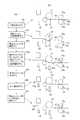
反射型センサ30で検出された情報(検出電圧)に基づいてラベル印刷機10で実行される印刷制御の一例について図4を参照して説明する。 An example of print control executed by the
図4は、印刷制御の一例を示すフロー図である。 FIG. 4 is a flowchart illustrating an example of print control.
このフローは、ラベル印刷機10(図1参照)の印刷開始ボタンが押されることにより起動する。先ず、プッシュスイッチセンサ20によって記録媒体Tの種類が検知される(S401)。この検知は、上述したように媒体カセット16の凹部で判定するので、媒体カセット16に実際に記録媒体Tが収容されている(残っている)か否かは判定できない。そこで、この検知によってラベルテープ40(図3参照)以外であると判定された場合は、反射型センサ30(図1参照)で記録媒体Tの有無を判定する(S402)。記録媒体Tがあると判定された場合、搬送モータ(図示せず)によって記録媒体Tを所定の位置まで搬送して印刷を開始する(S403)。印刷中は、記録媒体Tの有無を常時監視して(S404)、印刷データが無くなるまで(S405)印刷を継続する(S406)。S405において印刷データが無いと判定されたときは印刷動作を終了し(S417)、このフローを終了する。S404において記録媒体Tが無いと判定されたときは、表示部14(図1参照)に"媒体がありません"と表示して印刷を中断し(S407)、このフローを終了する。なお、S402において記録媒体Tが無いと判定されたときも同様に、表示部14に「媒体がありません」と表示して印刷を中断し(S407)、このフローを終了する。 This flow is activated when the print start button of the label printer 10 (see FIG. 1) is pressed. First, the type of the recording medium T is detected by the push switch sensor 20 (S401). As described above, since this detection is determined by the concave portion of the
S401においてラベルテープ40が収容された媒体カセット16であると判定されたときは、上記と同様に反射型センサ30で記録媒体Tの有無が判定される(S408)。ここで、記録媒体Tが有ると判定されたときは、続いて、反射型センサ30が検出した検出電圧が「剥がれ検出電圧(表1参照)」の範囲内か否かを判定する(S409)。「剥がれ検出電圧」では無いと判定された場合、搬送モータ(図示せず)によって記録媒体Tを所定の位置まで搬送して印刷を開始する(S410)。印刷中は、剥がれのレベル(S411)と記録媒体Tの有無を常時監視して(S412)、印刷データが無くなるまで(S413)印刷を継続する(S414)。S413において印刷データが無いと判定されたときは印刷動作を終了し(S418)、このフローを終了する。 When it is determined in S401 that the
S411において剥がれのレベルになっている(検出電圧が、表1に示す2.0V〜4.0Vの範囲内)と判定されたときは、印刷動作を停止して剥がれている部分(浮き部分、不具合部分)のカット動作(図5を参照して後述する)を実行して(S415)このフローを終了する。なお、S408において記録媒体Tが無いと判定されたときは、表示部14(図1参照)に「媒体がありません」と表示して印刷を中断し(S416)、このフローを終了する。 When it is determined in S411 that the level is peeled off (the detection voltage is within the range of 2.0 V to 4.0 V shown in Table 1), the printing operation is stopped and the part peeled off (floating part, The cutting operation (which will be described later with reference to FIG. 5) is executed (S415), and this flow ends. When it is determined in S408 that there is no recording medium T, “no medium” is displayed on the display unit 14 (see FIG. 1), printing is interrupted (S416), and this flow is ended.
上記した「浮き部分」のカット動作(除去)について図5を参照して説明する。 The above-described “floating portion” cutting operation (removal) will be described with reference to FIG.
図5(a)は、「浮き部分」を切断して除去するカット動作の手順を示すフロー図であり、(b)は、(a)のフローに対応する模式図である。図5では、図3に示すような不具合部分X(浮き部分40a)が発生したとする。 FIG. 5A is a flowchart showing the procedure of the cutting operation for cutting and removing the “floating portion”, and FIG. 5B is a schematic diagram corresponding to the flow of FIG. In FIG. 5, it is assumed that a defective portion X (floating
「浮き部分」のカット動作では、先ず、送りローラ18a(駆動ローラ)及びプラテンローラ24の回転を止めると同時に、サーマルヘッド22への通電を停止して印刷を停止する(S501)。続いて、不具合部分40aを通過させるために、加圧解除機構(図示せず)によって送りローラ18bを送りローラ18aから離す(離間させる)(S502)。続いて、不具合部分40aが送りローラ18a,18bのニップ部を通過するまで、プラテンローラ24をモータ(図示せず)で所定のパルス数だけ矢印A方向に回転させて停止させる(S503)。これにより、不具合部分40aは送りローラ18a,18bとプラテンローラ24の間に位置する。続いて、加圧解除機構(図示せず)によってプラテンローラ24からサーマルヘッド22を離し、送りローラ18a,18bでラベルテープ40を挟持する(S504)。 In the “floating portion” cutting operation, first, the rotation of the
この挟持した状態で、搬送モータ(図示せず)を駆動させて送りローラ18aを所定のパルス数だけ回転させてラベルテープ40を搬送させ、不具合部分40aがカッタ28を通過した時点で搬送モータを停止させる(S505)。ラベルテープ40のうち不具合部分40aよりもやや搬送方向上流側の部分をカッタ28で切断する(S506)。以上の動作によれば、不具合部分40aには画像が形成されないので、無駄な画像形成(無駄印刷)を防止できる。なお、不具合部分40aが除去されたラベルテープ40に再び印刷するために、ラベルテープ40を挟持している送りローラ18aを所定のパルス数だけ矢印C方向(矢印B方向とは反対の方向)回転させてラベルテープ40を逆方向に搬送させる(S507)。 In this sandwiched state, a conveyance motor (not shown) is driven to rotate the
反射型センサ30で検出された情報(検出電圧)に基づいてラベル印刷機10で実行される印刷制御の他の例について図6を参照して説明する。 Another example of print control executed by the
図6は、印刷制御の他の例を示すフロー図である。 FIG. 6 is a flowchart illustrating another example of print control.
図6のフローで示す印刷制御が、図5のフローで示す印刷制御と相違する主な点は、記録媒体Tの種類を検知しない点にある。即ち、プッシュスイッチセンサ20によって検知される記録媒体Tの種類に基づかない制御である。 The main difference between the print control shown in the flow of FIG. 6 and the print control shown in the flow of FIG. 5 is that the type of the recording medium T is not detected. That is, the control is not based on the type of the recording medium T detected by the
このフローは、ラベル印刷機10(図1参照)の印刷開始ボタンが押されることにより起動する。先ず、反射型センサ30によって媒体検出電圧を検出することにより記録媒体Tの有無を検出する(S601)。この場合、表1に示す媒体検出電圧が4.7V以上のときは、全ての種類の記録媒体Tが無いと判定して「媒体がありません」を表示部14(図1参照)に表示し(S602)、このフローを終了する。S601において検出された媒体検出電圧が4.7V未満のときは、この媒体検出電圧を初期値として記憶し(S603)、続いて、所定の位置で印刷を開始する(S604)。 This flow is activated when the print start button of the label printer 10 (see FIG. 1) is pressed. First, the presence or absence of the recording medium T is detected by detecting the medium detection voltage by the reflective sensor 30 (S601). In this case, when the medium detection voltage shown in Table 1 is 4.7 V or more, it is determined that there is no recording medium T of all types, and “no medium” is displayed on the display unit 14 (see FIG. 1) ( S602), this flow is finished. When the medium detection voltage detected in S601 is less than 4.7 V, the medium detection voltage is stored as an initial value (S603), and then printing is started at a predetermined position (S604).
印刷中は、記録媒体Tの有無を常時判定する(S605)。S605で記録媒体Tが無いと判定されたときはS602に進む。S605で記録媒体Tが有ると判定されたときは、この判定のために反射型センサ30で測定された媒体検出電圧が、S603で記憶された媒体検出電圧と変化していないか否かを判定する(S606)。S606において媒体検出電圧が変化していると判定されたときは、不具合部分が発生しているおそれがあるので、印刷を中止して「剥がれ(不具合部分)がありませんか?」を表示部14(図1参照)に表示し(S607)、このフローを終了する。S606において媒体検出電圧が変化していないと判定された場合、印刷データがあるか否かを判定し(S608)、印刷データがあるときは印刷を継続する(S609)。また、S608で印刷データが無いと判定されたときは印刷を終了し(S610)、このフローを終了する。なお、S606での電圧変化は、0.3V以上の変化があったときに「変化有り」と判定される。 During printing, the presence / absence of the recording medium T is always determined (S605). If it is determined in S605 that there is no recording medium T, the process proceeds to S602. If it is determined in S605 that the recording medium T is present, it is determined whether or not the medium detection voltage measured by the
以上説明したように、図6に示す印刷制御によれば、プッシュスイッチセンサ20によって記録媒体Tの種類を検知しなくても不具合部分(剥がれ)を検出できる。この結果、装置を低コストに抑えつつ、不具合画像が発生する前に印刷動作を止めるので無駄印刷を防止できる。 As described above, according to the printing control shown in FIG. 6, it is possible to detect a defective portion (peeling) without detecting the type of the recording medium T by the
10 ラベル印刷機
16 媒体カセット
18a、18b 一対の送りローラ
20 プッシュスイッチセンサ
28 カッタ
30 反射型センサ
40 ラベルテープ
42 剥離紙
44 ラベルDESCRIPTION OF
Claims (7)
Translated fromJapanese搬送中の記録媒体の不具合部分を検出する検出手段を備えたことを特徴とする画像形成装置。In an image forming apparatus for forming an image on a recording medium while conveying a long recording medium,
An image forming apparatus comprising: a detecting unit that detects a defective portion of a recording medium being conveyed.
長尺状の剥離紙と、この剥離紙に貼り付けられたラベルとからなる記録媒体の前記ラベルの一部が剥がれた不具合部分を検出するものであることを特徴とする請求項1に記載の画像形成装置。The detection means includes
2. The apparatus according to claim 1, wherein a defective portion in which a part of the label of a recording medium including a long release paper and a label attached to the release paper is removed is detected. Image forming apparatus.
前記不具合部分を切断して除去するカッタであることを特徴とする請求項1,2,又は3に記載の画像形成装置。The removing means includes
The image forming apparatus according to claim 1, wherein the image forming apparatus is a cutter that cuts and removes the defective portion.
前記検出手段は、前記搬送手段よりも前記搬送方向上流側に配置されたものであり、
前記検出手段が前記不具合部分を検出したときは、前記搬送手段の挟持を解除して前記不具合部分を前記除去手段まで搬送させることを特徴とする請求項2,3,又は4に記載の画像形成装置。A transport unit disposed on the upstream side in the transport direction from the removing unit and sandwiching and transporting the recording medium;
The detection means is arranged on the upstream side in the transport direction with respect to the transport means,
5. The image formation according to claim 2, wherein when the detection unit detects the defective portion, the nipping of the conveyance unit is released and the defective portion is conveyed to the removal unit. apparatus.
記録媒体の有無も検出するものであることを特徴とする請求項1から5までのうちのいずれか一項に記載の画像形成装置。The detection means includes
6. The image forming apparatus according to claim 1, wherein the presence or absence of a recording medium is also detected.
前記検出手段は、記録媒体との距離に対応する電圧に基づいて前記不具合部分又は記録媒体の有無を検出するものであり、且つ、前記種類検知手段で検知された記録媒体の種類に基づいて検出結果を変更するものであることを特徴とする請求項1から5までのうちのいずれか一項に記載の画像形成装置。Provided with a type detection means for detecting the type of recording medium,
The detecting means detects the presence or absence of the defective portion or the recording medium based on a voltage corresponding to a distance from the recording medium, and detects based on the type of the recording medium detected by the type detecting means. 6. The image forming apparatus according to claim 1, wherein the result is changed.
Priority Applications (1)
| Application Number | Priority Date | Filing Date | Title |
|---|---|---|---|
| JP2005257937AJP4607716B2 (en) | 2005-09-06 | 2005-09-06 | Image forming apparatus |
Applications Claiming Priority (1)
| Application Number | Priority Date | Filing Date | Title |
|---|---|---|---|
| JP2005257937AJP4607716B2 (en) | 2005-09-06 | 2005-09-06 | Image forming apparatus |
Publications (3)
| Publication Number | Publication Date |
|---|---|
| JP2007070028Atrue JP2007070028A (en) | 2007-03-22 |
| JP2007070028A5 JP2007070028A5 (en) | 2008-10-16 |
| JP4607716B2 JP4607716B2 (en) | 2011-01-05 |
Family
ID=37931825
Family Applications (1)
| Application Number | Title | Priority Date | Filing Date |
|---|---|---|---|
| JP2005257937AExpired - Fee RelatedJP4607716B2 (en) | 2005-09-06 | 2005-09-06 | Image forming apparatus |
Country Status (1)
| Country | Link |
|---|---|
| JP (1) | JP4607716B2 (en) |
Cited By (11)
| Publication number | Priority date | Publication date | Assignee | Title |
|---|---|---|---|---|
| JP2013199058A (en)* | 2012-03-26 | 2013-10-03 | Seiko Epson Corp | Tape processing device and tape cartridge |
| CN106004125A (en)* | 2009-06-30 | 2016-10-12 | 兄弟工业株式会社 | Tape cassette |
| US9855779B2 (en) | 2008-12-25 | 2018-01-02 | Brother Kogyo Kabushiki Kaisha | Tape cassette |
| US10189284B2 (en) | 2008-12-25 | 2019-01-29 | Brother Kogyo Kabushiki Kaisha | Tape cassette |
| US10201993B2 (en) | 2009-03-31 | 2019-02-12 | Brother Kogyo Kabushiki Kaisha | Tape cassette |
| US10201988B2 (en) | 2009-03-31 | 2019-02-12 | Brother Kogyo Kabushiki Kaisha | Tape cassette |
| US10265976B2 (en) | 2009-12-16 | 2019-04-23 | Brother Kogyo Kabushiki Kaisha | Tape cassette |
| US10265982B2 (en) | 2009-12-28 | 2019-04-23 | Brother Kogyo Kabushiki Kaisha | Tape cassette |
| JP2021109428A (en)* | 2020-01-15 | 2021-08-02 | 東芝テック株式会社 | Label printer and label printer control program |
| CN114953761A (en)* | 2021-02-16 | 2022-08-30 | 精工爱普生株式会社 | Information processing apparatus, control method, recording medium, tape printing apparatus, and tape printing system |
| US12296580B2 (en) | 2009-03-31 | 2025-05-13 | Brother Kogyo Kabushiki Kaisha | Tape cassette |
Families Citing this family (1)
| Publication number | Priority date | Publication date | Assignee | Title |
|---|---|---|---|---|
| JP4810257B2 (en)* | 2006-03-02 | 2011-11-09 | キヤノン株式会社 | Image forming apparatus |
Citations (5)
| Publication number | Priority date | Publication date | Assignee | Title |
|---|---|---|---|---|
| JPS60184869A (en)* | 1984-03-02 | 1985-09-20 | Teraoka Seiko Co Ltd | Printer |
| JPH05164697A (en)* | 1991-12-16 | 1993-06-29 | Sekisui Chem Co Ltd | Method and device for detecting surface condition of sheet like roll |
| JPH07108774A (en)* | 1993-10-12 | 1995-04-25 | Fujicopian Co Ltd | Image receptor for tape printer |
| JPH09169132A (en)* | 1995-12-20 | 1997-06-30 | Victor Co Of Japan Ltd | Thermal transfer printer |
| JP2004149135A (en)* | 2002-10-29 | 2004-05-27 | Sato Corp | Label printer and print control method thereof |
- 2005
- 2005-09-06JPJP2005257937Apatent/JP4607716B2/ennot_activeExpired - Fee Related
Patent Citations (5)
| Publication number | Priority date | Publication date | Assignee | Title |
|---|---|---|---|---|
| JPS60184869A (en)* | 1984-03-02 | 1985-09-20 | Teraoka Seiko Co Ltd | Printer |
| JPH05164697A (en)* | 1991-12-16 | 1993-06-29 | Sekisui Chem Co Ltd | Method and device for detecting surface condition of sheet like roll |
| JPH07108774A (en)* | 1993-10-12 | 1995-04-25 | Fujicopian Co Ltd | Image receptor for tape printer |
| JPH09169132A (en)* | 1995-12-20 | 1997-06-30 | Victor Co Of Japan Ltd | Thermal transfer printer |
| JP2004149135A (en)* | 2002-10-29 | 2004-05-27 | Sato Corp | Label printer and print control method thereof |
Cited By (33)
| Publication number | Priority date | Publication date | Assignee | Title |
|---|---|---|---|---|
| US12304229B2 (en) | 2008-12-25 | 2025-05-20 | Brother Kogyo Kabushiki Kaisha | Tape cassette |
| US11479053B2 (en) | 2008-12-25 | 2022-10-25 | Brother Kogyo Kabushiki Kaisha | Tape cassette |
| US9855779B2 (en) | 2008-12-25 | 2018-01-02 | Brother Kogyo Kabushiki Kaisha | Tape cassette |
| US10189284B2 (en) | 2008-12-25 | 2019-01-29 | Brother Kogyo Kabushiki Kaisha | Tape cassette |
| US12233641B2 (en) | 2008-12-25 | 2025-02-25 | Brother Kogyo Kabushiki Kaisha | Tape cassette |
| US11285749B2 (en) | 2008-12-25 | 2022-03-29 | Brother Kogyo Kabushiki Kaisha | Tape cassette |
| US10744798B2 (en) | 2008-12-25 | 2020-08-18 | Brother Kogyo Kabushiki Kaisha | Tape cassette |
| US10661589B2 (en) | 2008-12-25 | 2020-05-26 | Brother Kogyo Kabushiki Kaisha | Tape cassette |
| US10226949B2 (en) | 2009-03-31 | 2019-03-12 | Brother Kogyo Kabushiki Kaisha | Tape cassette |
| US10201993B2 (en) | 2009-03-31 | 2019-02-12 | Brother Kogyo Kabushiki Kaisha | Tape cassette |
| US11707938B2 (en) | 2009-03-31 | 2023-07-25 | Brother Kogyo Kabushiki Kaisha | Tape cassette |
| US10675894B2 (en) | 2009-03-31 | 2020-06-09 | Brother Kogyo Kabushiki Kaisha | Tape cassette |
| US11945217B2 (en) | 2009-03-31 | 2024-04-02 | Brother Kogyo Kabushiki Kaisha | Tape cassette |
| US10744802B2 (en) | 2009-03-31 | 2020-08-18 | Brother Kogyo Kabushiki Kaisha | Tape cassette |
| US11052685B2 (en) | 2009-03-31 | 2021-07-06 | Brother Kogyo Kabushiki Kaisha | Tape cassette |
| US12296580B2 (en) | 2009-03-31 | 2025-05-13 | Brother Kogyo Kabushiki Kaisha | Tape cassette |
| US12257827B2 (en) | 2009-03-31 | 2025-03-25 | Brother Kogyo Kabushiki Kaisha | Tape cassette |
| US10618325B2 (en) | 2009-03-31 | 2020-04-14 | Brother Kogyo Kabushiki Kaisha | Tape cassette |
| US10201988B2 (en) | 2009-03-31 | 2019-02-12 | Brother Kogyo Kabushiki Kaisha | Tape cassette |
| US11254149B2 (en) | 2009-03-31 | 2022-02-22 | Brother Kogyo Kabushiki Kaisha | Tape cassette |
| US11225099B2 (en) | 2009-06-30 | 2022-01-18 | Brother Kogyo Kabushiki Kaisha | Tape cassette |
| CN106004125A (en)* | 2009-06-30 | 2016-10-12 | 兄弟工业株式会社 | Tape cassette |
| US12194765B2 (en) | 2009-06-30 | 2025-01-14 | Brother Kogyo Kabushiki Kaisha | Tape cassette |
| US11235600B2 (en) | 2009-12-16 | 2022-02-01 | Brother Kogyo Kabushiki Kaisha | Tape cassette |
| US10265976B2 (en) | 2009-12-16 | 2019-04-23 | Brother Kogyo Kabushiki Kaisha | Tape cassette |
| US11135862B2 (en) | 2009-12-28 | 2021-10-05 | Brother Kogyo Kabushiki Kaisha | Tape cassette with indicator portion having pressing and non-pressing portion for indentifying tape type |
| US12128697B2 (en) | 2009-12-28 | 2024-10-29 | Brother Kogyo Kabushiki Kaisha | Tape cassette |
| US10265982B2 (en) | 2009-12-28 | 2019-04-23 | Brother Kogyo Kabushiki Kaisha | Tape cassette |
| JP2013199058A (en)* | 2012-03-26 | 2013-10-03 | Seiko Epson Corp | Tape processing device and tape cartridge |
| JP7455586B2 (en) | 2020-01-15 | 2024-03-26 | 東芝テック株式会社 | Label printer and label printer control program |
| JP2021109428A (en)* | 2020-01-15 | 2021-08-02 | 東芝テック株式会社 | Label printer and label printer control program |
| CN114953761B (en)* | 2021-02-16 | 2023-09-15 | 精工爱普生株式会社 | Information processing device and control method, recording medium, tape printing device and system |
| CN114953761A (en)* | 2021-02-16 | 2022-08-30 | 精工爱普生株式会社 | Information processing apparatus, control method, recording medium, tape printing apparatus, and tape printing system |
Also Published As
| Publication number | Publication date |
|---|---|
| JP4607716B2 (en) | 2011-01-05 |
Similar Documents
| Publication | Publication Date | Title |
|---|---|---|
| JP4607716B2 (en) | Image forming apparatus | |
| CN110293770B (en) | Printing device, control method, and recording medium | |
| CN110281659B (en) | Printing apparatus and label detection method | |
| JP2008080668A (en) | Printing tape, tape cassette and tape printing device | |
| US6592217B2 (en) | Recording apparatus | |
| EP2043872A2 (en) | Tape printing apparatus and tape cassette | |
| WO2010047153A1 (en) | Tape printer | |
| CN110271308A (en) | Printing equipment, control method and non-transitory storage medium | |
| JP2006016167A (en) | Paper feeding device | |
| JP2005262491A (en) | Roll paper and roll paper printer using the same | |
| JPH07172649A (en) | Residual quality detecting device for roll winding recording medium | |
| JP2000289908A (en) | Image forming device | |
| JP2006069015A (en) | Printer | |
| JP4525537B2 (en) | Tape for tape printer and tape printer using the same | |
| JP5009997B2 (en) | Tape-shaped recording medium feeding guide and printer having the same | |
| JP2007136913A (en) | Label printer | |
| JP2003191557A (en) | Ink ribbon cassette and printer | |
| JP3013554B2 (en) | Printing device | |
| JP4256154B2 (en) | Thermal transfer printer | |
| JP2003191543A (en) | Printer | |
| JP4838656B2 (en) | Thermal transfer printer | |
| JP2005096193A (en) | Image forming device | |
| JP2003191548A (en) | Printing apparatus | |
| JP2002254741A (en) | Label printer | |
| JP2017087605A (en) | Printing apparatus and conveying method |
Legal Events
| Date | Code | Title | Description |
|---|---|---|---|
| A521 | Written amendment | Free format text:JAPANESE INTERMEDIATE CODE: A523 Effective date:20080903 | |
| A621 | Written request for application examination | Free format text:JAPANESE INTERMEDIATE CODE: A621 Effective date:20080903 | |
| A711 | Notification of change in applicant | Free format text:JAPANESE INTERMEDIATE CODE: A711 Effective date:20090122 | |
| A521 | Written amendment | Free format text:JAPANESE INTERMEDIATE CODE: A821 Effective date:20090123 | |
| A521 | Written amendment | Free format text:JAPANESE INTERMEDIATE CODE: A523 Effective date:20090219 | |
| A521 | Written amendment | Free format text:JAPANESE INTERMEDIATE CODE: A523 Effective date:20090320 | |
| RD01 | Notification of change of attorney | Free format text:JAPANESE INTERMEDIATE CODE: A7421 Effective date:20091225 | |
| A977 | Report on retrieval | Free format text:JAPANESE INTERMEDIATE CODE: A971007 Effective date:20100210 | |
| A131 | Notification of reasons for refusal | Free format text:JAPANESE INTERMEDIATE CODE: A131 Effective date:20100416 | |
| A521 | Written amendment | Free format text:JAPANESE INTERMEDIATE CODE: A523 Effective date:20100615 | |
| TRDD | Decision of grant or rejection written | ||
| A01 | Written decision to grant a patent or to grant a registration (utility model) | Free format text:JAPANESE INTERMEDIATE CODE: A01 Effective date:20100910 | |
| A01 | Written decision to grant a patent or to grant a registration (utility model) | Free format text:JAPANESE INTERMEDIATE CODE: A01 | |
| A61 | First payment of annual fees (during grant procedure) | Free format text:JAPANESE INTERMEDIATE CODE: A61 Effective date:20101007 | |
| R150 | Certificate of patent or registration of utility model | Free format text:JAPANESE INTERMEDIATE CODE: R150 Ref document number:4607716 Country of ref document:JP Free format text:JAPANESE INTERMEDIATE CODE: R150 | |
| FPAY | Renewal fee payment (event date is renewal date of database) | Free format text:PAYMENT UNTIL: 20131015 Year of fee payment:3 | |
| R250 | Receipt of annual fees | Free format text:JAPANESE INTERMEDIATE CODE: R250 | |
| R250 | Receipt of annual fees | Free format text:JAPANESE INTERMEDIATE CODE: R250 | |
| R250 | Receipt of annual fees | Free format text:JAPANESE INTERMEDIATE CODE: R250 | |
| R250 | Receipt of annual fees | Free format text:JAPANESE INTERMEDIATE CODE: R250 | |
| R250 | Receipt of annual fees | Free format text:JAPANESE INTERMEDIATE CODE: R250 | |
| S111 | Request for change of ownership or part of ownership | Free format text:JAPANESE INTERMEDIATE CODE: R313111 | |
| R350 | Written notification of registration of transfer | Free format text:JAPANESE INTERMEDIATE CODE: R350 | |
| R250 | Receipt of annual fees | Free format text:JAPANESE INTERMEDIATE CODE: R250 | |
| LAPS | Cancellation because of no payment of annual fees |