JP2007068622A - Acquisition system for biological information of subject - Google Patents
Acquisition system for biological information of subjectDownload PDFInfo
- Publication number
- JP2007068622A JP2007068622AJP2005256262AJP2005256262AJP2007068622AJP 2007068622 AJP2007068622 AJP 2007068622AJP 2005256262 AJP2005256262 AJP 2005256262AJP 2005256262 AJP2005256262 AJP 2005256262AJP 2007068622 AJP2007068622 AJP 2007068622A
- Authority
- JP
- Japan
- Prior art keywords
- pad
- subject
- signal
- unit
- capsule endoscope
- Prior art date
- Legal status (The legal status is an assumption and is not a legal conclusion. Google has not performed a legal analysis and makes no representation as to the accuracy of the status listed.)
- Withdrawn
Links
Images


Classifications
- A—HUMAN NECESSITIES
- A61—MEDICAL OR VETERINARY SCIENCE; HYGIENE
- A61B—DIAGNOSIS; SURGERY; IDENTIFICATION
- A61B5/00—Measuring for diagnostic purposes; Identification of persons
- A61B5/07—Endoradiosondes
- A—HUMAN NECESSITIES
- A61—MEDICAL OR VETERINARY SCIENCE; HYGIENE
- A61B—DIAGNOSIS; SURGERY; IDENTIFICATION
- A61B1/00—Instruments for performing medical examinations of the interior of cavities or tubes of the body by visual or photographical inspection, e.g. endoscopes; Illuminating arrangements therefor
- A61B1/00002—Operational features of endoscopes
- A61B1/00011—Operational features of endoscopes characterised by signal transmission
- A61B1/00016—Operational features of endoscopes characterised by signal transmission using wireless means
- A—HUMAN NECESSITIES
- A61—MEDICAL OR VETERINARY SCIENCE; HYGIENE
- A61B—DIAGNOSIS; SURGERY; IDENTIFICATION
- A61B1/00—Instruments for performing medical examinations of the interior of cavities or tubes of the body by visual or photographical inspection, e.g. endoscopes; Illuminating arrangements therefor
- A61B1/04—Instruments for performing medical examinations of the interior of cavities or tubes of the body by visual or photographical inspection, e.g. endoscopes; Illuminating arrangements therefor combined with photographic or television appliances
- A61B1/041—Capsule endoscopes for imaging
- A—HUMAN NECESSITIES
- A61—MEDICAL OR VETERINARY SCIENCE; HYGIENE
- A61B—DIAGNOSIS; SURGERY; IDENTIFICATION
- A61B1/00—Instruments for performing medical examinations of the interior of cavities or tubes of the body by visual or photographical inspection, e.g. endoscopes; Illuminating arrangements therefor
- A61B1/273—Instruments for performing medical examinations of the interior of cavities or tubes of the body by visual or photographical inspection, e.g. endoscopes; Illuminating arrangements therefor for the upper alimentary canal, e.g. oesophagoscopes, gastroscopes
- A—HUMAN NECESSITIES
- A61—MEDICAL OR VETERINARY SCIENCE; HYGIENE
- A61B—DIAGNOSIS; SURGERY; IDENTIFICATION
- A61B5/00—Measuring for diagnostic purposes; Identification of persons
- A61B5/0002—Remote monitoring of patients using telemetry, e.g. transmission of vital signals via a communication network
- A61B5/0004—Remote monitoring of patients using telemetry, e.g. transmission of vital signals via a communication network characterised by the type of physiological signal transmitted
- A61B5/0013—Medical image data
Landscapes
- Health & Medical Sciences (AREA)
- Life Sciences & Earth Sciences (AREA)
- Surgery (AREA)
- Engineering & Computer Science (AREA)
- General Health & Medical Sciences (AREA)
- Molecular Biology (AREA)
- Pathology (AREA)
- Veterinary Medicine (AREA)
- Public Health (AREA)
- Biophysics (AREA)
- Biomedical Technology (AREA)
- Heart & Thoracic Surgery (AREA)
- Medical Informatics (AREA)
- Physics & Mathematics (AREA)
- Animal Behavior & Ethology (AREA)
- Optics & Photonics (AREA)
- Nuclear Medicine, Radiotherapy & Molecular Imaging (AREA)
- Radiology & Medical Imaging (AREA)
- Computer Networks & Wireless Communication (AREA)
- Endoscopes (AREA)
- Measurement Of The Respiration, Hearing Ability, Form, And Blood Characteristics Of Living Organisms (AREA)
Abstract
Description
Translated fromJapanese本発明は、被検体内に設置した装置と被検体外に設置した装置との間で、被検体内の情報を通信する被検体内情報取得システムに関する。 The present invention relates to an in-subject information acquisition system for communicating information in a subject between a device installed in the subject and a device installed outside the subject.
近年、被検体、特に生体内を検査、治療する分野においては、生体内または生体近傍で取得した生体に関する情報を、生体外へ通信する必要がある。生体外へ情報を通信するために、電波通信による構成が提案されている(例えば、特許文献1参照。)。特許文献1においては、生体内情報を得るために生体内に挿入される、生体内センサと送信機を含む装置と、生体内情報を受信する受信機を備えるシステムが開示されている。そして、送信機はワイヤレス送信または電波送信を行なうことで、生体外との情報のやり取りを行なっている。 In recent years, in the field of examining and treating a subject, particularly a living body, it is necessary to communicate information about the living body acquired in or near the living body to the outside of the living body. In order to communicate information outside the living body, a configuration using radio wave communication has been proposed (for example, see Patent Document 1).
また、生体の情報を外部へ伝達するために、生体に微弱電流を流して、通信を行なう構成も提案されている(例えば、特許文献2参照。)。特許文献2に開示された装置は、キャリアに信号を重畳して変調を加えた微弱な変調電流を生体に流す変調電流発生手段を有している。また、生体外および/または生体内に配置される受信部は、双方の電極のうち受信側の電極を介して微弱な変調電流を受信するように構成されている。 Moreover, in order to transmit the biological information to the outside, a configuration has also been proposed in which a weak current is passed through the living body to perform communication (see, for example, Patent Document 2). The device disclosed in Patent Document 2 has modulation current generating means for passing a weak modulation current, which is modulated by superimposing a signal on a carrier, to the living body. In addition, the receiving unit arranged outside and / or inside the living body is configured to receive a weak modulation current via the receiving-side electrode of both electrodes.
しかしながら、特許文献1のように、生体内と生体外とを電波により通信する構成では、以下の(1)、(2)、(3)の問題点があり、患者(生体)の負担が大きくなってしまう。
(1)法規制により使用できる周波数には制限があり、生体内外の通信に最適な周波数が任意に選べないこと。
(2)送受信用に生体内外にアンテナを設置する必要がある。そして、電波は生体で減衰等するため、生体外に設置するアンテナは大掛かりで多数必要となる。このため、患者への負担が大きくなってしまうこと。
(3)また、生体における電波の減衰等を考慮すると、高い電波出力が必要となる。このため、生体内外の装置が大型化してしまい、やはり患者への負担が大きくなってしまうこと。However, as in
(1) There are restrictions on the frequencies that can be used due to laws and regulations, and it is not possible to arbitrarily select the optimal frequency for in-vivo and external communications.
(2) It is necessary to install an antenna inside and outside the living body for transmission and reception. Since radio waves are attenuated in a living body, a large number of antennas installed outside the living body are required. This increases the burden on the patient.
(3) Considering attenuation of radio waves in a living body, high radio wave output is required. For this reason, the apparatus inside and outside a living body will enlarge, and the burden on a patient will also become large.
また、特許文献2に記載の構成のように、生体に微弱電流を流して通信するときも、微弱電流を検出し復調するためには、受信側の装置が大型化してしまう。このため、患者(生体)の負担が大きくなってしまうという問題を生ずる。 Also, as in the configuration described in Patent Document 2, when a weak current is passed through a living body for communication, the receiving-side apparatus becomes large in order to detect and demodulate the weak current. For this reason, the problem that the burden of a patient (living body) will become large arises.
本発明は、上記に鑑みてなされたものであって、生体内外の装置をアンテナの設置などで大掛かりにする必要がなく、小型で患者(生体)の負担を軽減した被検体内情報取得システムを提供することを目的とする。 The present invention has been made in view of the above, and it is not necessary to increase the size of an in-vivo / ex-vivo apparatus by installing an antenna, and the like. The purpose is to provide.
上述した課題を解決し、目的を達成するために、本発明によれば、被検体の内部に導入される被検体内導入装置と、被検体の外部に配置され、被検体内導入装置との間で通信を行なう体外装置とを備えた被検体内情報取得システムにおいて、被検体内導入装置は、少なくとも第1のパッドを備え、体外装置は、少なくとも第2のパッドを備え、第1のパッドと第2のパッドとの間で信号の送受信を行うために、被検体内導入装置と体外装置との少なくともいずれか一方の装置は、いずれか一方の装置のパッドに信号を変調して電圧印加する変調手段を備え、他方の装置は、他方の装置のパッドの電位変化から信号復調する復調手段を備えていることを特徴とする被検体内情報取得システムを提供できる。 In order to solve the above-described problems and achieve the object, according to the present invention, there is provided an intra-subject introduction device that is introduced into the subject and an intra-subject introduction device that is disposed outside the subject. In an in-subject information acquisition system including an extracorporeal device that communicates between the subject, the in-subject introduction device includes at least a first pad, the extracorporeal device includes at least a second pad, and the first pad. In order to transmit and receive signals between the first pad and the second pad, at least one of the in-subject introduction device and the extracorporeal device modulates the signal to the pad of either device and applies a voltage. The intra-subject information acquisition system can be provided in which the other device includes a demodulating unit that demodulates a signal from a change in potential of the pad of the other device.
また、本発明の好ましい態様によれば、被検体内導入装置は、被検体の被検部位を撮像して少なくとも映像信号を出力する撮像部を有し、体外装置は、映像信号を復調することが望ましい。 Further, according to a preferred aspect of the present invention, the in-subject introduction device has an imaging unit that images at least a test site of the subject and outputs at least a video signal, and the extracorporeal device demodulates the video signal. Is desirable.
また、本発明の好ましい態様によれば、体外装置の第2のパッドは、被検体の表面に接触するように配置されていることが望ましい。 According to a preferred aspect of the present invention, it is desirable that the second pad of the extracorporeal device is disposed so as to contact the surface of the subject.
また、本発明の好ましい態様によれば、第1のパッドと第2のパッドとの少なくともいずれか一方のパッドの表面に絶縁体が形成されていることが望ましい。 According to a preferred aspect of the present invention, it is desirable that an insulator is formed on the surface of at least one of the first pad and the second pad.
また、本発明の好ましい態様によれば、第1のパッドは、被検体内導入装置の表面に形成されていることが望ましい。 According to a preferred aspect of the present invention, it is desirable that the first pad is formed on the surface of the in-subject introduction device.
また、本発明の好ましい態様によれば、被検体内導入装置は、被検体の内部へ導入可能な有底の円筒形状に形成された外装部を備えるカプセル型内視鏡であり、第1のパッドは、カプセル型内視鏡の表面に形成されていることが望ましい。 Further, according to a preferred aspect of the present invention, the in-subject introduction device is a capsule endoscope including an exterior part formed in a bottomed cylindrical shape that can be introduced into the subject, and the first endoscope The pad is preferably formed on the surface of the capsule endoscope.
また、本発明の好ましい態様によれば、カプセル型内視鏡から体外装置へ、少なくとも映像信号が伝送され、体外装置からカプセル型内視鏡へ、少なくともカプセル型内視鏡を駆動するための電力が伝送されることが望ましい。 According to a preferred aspect of the present invention, at least a video signal is transmitted from the capsule endoscope to the extracorporeal device, and power for driving at least the capsule endoscope from the extracorporeal device to the capsule endoscope. Is preferably transmitted.
本発明に係る被検体内情報取得システムは、被検体内導入装置の第1のパッドと、体外装置の第2のパッドとの間で、一方の装置ではパッドに信号を変調して電圧印加する。また、他方の装置では、パッドの電位変化から信号を復調する。これにより、被検体内導入装置と体外装置との間においては、電波や電流を用いずに情報の通信を行うことができる。このため、例えば、被検体内導入装置から体外装置へ情報を通信するとき、被検体内導入装置に関しては、アンテナや送信回路が不要となる、従って、被検体内導入装置を小型化できる。また、体外装置に関しても、被検体、例えば患者の体の周辺に多数の受信用のアンテナを配置する構成や微弱電流の検出、復調回路が必要ない。従って、生体内外の装置をアンテナの設置などで大掛かりにする必要がない。この結果、小型で患者(生体)の負担を軽減した被検体内情報取得システムを提供することができる。 The in-subject information acquisition system according to the present invention modulates a signal between the first pad of the intra-subject introduction device and the second pad of the extracorporeal device and applies a voltage to the pad in one device. . In the other device, the signal is demodulated from the potential change of the pad. Thus, information can be communicated between the in-subject introduction apparatus and the extracorporeal apparatus without using radio waves or current. For this reason, for example, when communicating information from the intra-subject introduction apparatus to the extracorporeal apparatus, the intra-subject introduction apparatus does not require an antenna or a transmission circuit. Therefore, the intra-subject introduction apparatus can be reduced in size. Further, regarding an extracorporeal device, a configuration in which a large number of receiving antennas are arranged around the subject, for example, a patient's body, and a weak current detection / demodulation circuit are not required. Therefore, it is not necessary to enlarge the apparatus inside and outside the living body by installing an antenna or the like. As a result, it is possible to provide an in-subject information acquisition system that is small and reduces the burden on the patient (living body).
以下に、本発明に係る被検体内情報取得システムの実施例を図面に基づいて詳細に説明する。なお、この実施例によりこの発明が限定されるものではない。 Embodiments of an in-vivo information acquiring system according to the present invention will be described below in detail with reference to the drawings. Note that the present invention is not limited to the embodiments.
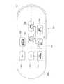
図1は、本発明の実施例1に係る被検体内情報取得システムの概略構成を示す図である。被検体として、生体10、例えば患者の体内情報を取得する場合を示している。カプセル型内視鏡100は、観察(検査)のために患者の口から飲込まれた後、人体から自然排出されるまでの観察期間、胃、小腸などの臓器の内部をその蠕動運動に伴って移動して順次撮像する機能を有している。 FIG. 1 is a diagram illustrating a schematic configuration of an in-vivo information acquiring system according to
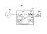
図2は、カプセル型内視鏡100の概略の外観構成を示している。カプセル型内視鏡100は、被検体内導入装置に対応する。そして、カプセル型内視鏡100は、生体10の内部へ導入可能な有底の円筒形状に形成された外装部120を備えている。また、後述する第1のパッド109は、カプセル型内視鏡100の表面に形成されている。また、第1のパッド109が形成されている側とは反対側には、CCD103が形成されている。なお、環状の第2のパッド110については、実施例2において後述する。 FIG. 2 shows a schematic external configuration of the
臓器内の移動による観察期間、カプセル型内視鏡100によって体内で撮像された画像データは、順次、後述する通信手順により生体外の体外装置200に送信される。カプセル型内視鏡100と体外装置200とで被検体内情報取得システムを構成する。まず、はじめにカプセル型内視鏡100の構成について説明し、その後、体外装置200の構成について説明する。 During the observation period due to movement in the organ, image data captured inside the body by the
図3は、カプセル型内視鏡100の機能ブロックを示している。カプセル型内視鏡100は、生体10の内部を撮影する際に撮像領域を照射するためのLED101と、LED101の駆動状態を制御するLED駆動回路102と、LED101によって照射された被検体の領域の撮像を行なうCCD103とを備えている。また、カプセル型内視鏡100は、CCD103の駆動状態を制御するCCD駆動回路104と、CCD103によって撮像された画像データ(映像信号)等を処理する第1の信号処理ユニット105と、第1の信号処理ユニット105からの生体内情報信号を変調する変調ユニット106と、変調ユニット106からの変調された電圧が印加される第1のパッド109と、LED駆動回路102、CCD駆動回路104、第1の信号処理ユニット105及び変調ユニット106の動作を制御するシステムコントロール回路107とを備えている。また、電源ユニット108は、カプセル型内視鏡100内の各ユニット、回路等に対して電力を供給する。 FIG. 3 shows functional blocks of the
CCD103は、生体10内の画像情報などの生体内情報を取得する。CCD103は、撮像部に対応し、生体内情報センサとしての機能を有する。撮像部としては、CCD103の他にCMOS等を用いることができる。カプセル型内視鏡100の外装の少なくとも一部の窓120aは、例えば透明な材質で形成されている。CCD103は、窓120aを介して生体10の画像を撮像する。 The
CCD103は、CCD駆動回路104に接続されている。CCD駆動回路104は、CCD103が生体内情報を取得するための動作信号をCCD103へ出力する。CCD103は、第1の信号処理ユニット105に接続されている。信号処置ユニット105は、生体内情報処理装置としての機能を有する。第1の信号処理ユニット105は、例えばCCD103からの出力の画像化回路やデータ圧縮回路などで構成されている。そして、第1の信号処理ユニット105は、CCD103の出力信号から生体内情報信号を生成し出力する。 The
システムコントロール回路107を介してCCD駆動回路104と、第1の信号処理ユニット105とは、変調ユニット106へ接続されている。変調ユニット106は、第1の信号処理ユニット105の出力信号を変調して第1のパッド109に電圧印加する。 The
第1のパッド109は、例えば銅(Cu)やニッケル(Ni)などの生体に対して有害な物質を含まない材料で形成されている。一般的には、第1のパッド109は、白金(Pt)や金(Au)などで形成されている。 The
第1のパッド109は、カプセル型内視鏡100の外部表面に形成されている。カプセル型内視鏡100の内部は密封構造となっている。第1のパッド109は、カプセル型内視鏡100の密封状態を保持した状態で、変調ユニット106に接続されている。第1のパッド109と変調ユニット106とは、例えば、カプセル型内視鏡100の貫通穴(不図示)を通過して接続した後、貫通穴を樹脂や金属などで充填密封して構成する。次に、体外装置200について説明する。 The
図4は、体外装置200の機能ブロックを示している。第2のパッド201は、生体10の体表面に設置されている。そして、第2のパッド201は、携帯ユニット206内の復調ユニット202に接続されている。携帯ユニット206は、例えば、生体10の腰ベルト近傍などに装着されている。 FIG. 4 shows functional blocks of the
携帯ユニット206は、復調ユニット202と、第2の信号処理ユニット203と、記録ユニット205と、電源ユニット207とを備えている。復調ユニット202は、第2のパッド201の表面の電位変化から、第1の信号処理ユニット105の出力信号を復調する。 The
第1のパッド105に対して第1の信号処理ユニット105の出力信号を変調した電圧印加することによって、第2のパッド201表面の電位に変化が生ずる。復調ユニット202は、第1の信号処理ユニット105の出力信号を復調する。これにより、生体10内側から外側への通信を実現できる。 By applying a voltage obtained by modulating the output signal of the first
第2のパッド201は、例えば銅(Cu)やニッケル(Ni)などの生体に対して有害な物質を含まない材料形成されている。第2のパッド201は、一般的には白金(Pt)や金(Au)などで形成されている。 The
図5は、第2のパッド201の断面構造を示している。第2のパッド201は、体表面と密着するために、樹脂フィルムやリボンなどの基材201aで、白金(Pt)や金(Au)などの薄膜201bを挟み込んだ構造となっている。さらに、体表面と接触する部分は、例えばシリコン樹脂などの絶縁薄膜201cが形成されている。体表面と接触する絶縁薄膜201cの厚さは、例えば1mm以下などの生体表面の電位を第2の信号処理ユニット203で検出できる程度の厚さであることが望ましい。また、生体10の体表面と第2のパッド201との間にゲルやオイルを塗布しても良い。これにより、さらに第2のパッド201と体表面との密着度を高くできる。 FIG. 5 shows a cross-sectional structure of the
このように、本実施例では、電流によらない情報通信を行なっているため、第2のパッド201を絶縁構造にできる。このため、生体10に対する安全性を向上できる。 As described above, in the present embodiment, since the information communication independent of the current is performed, the
図4に戻って説明を続ける。復調ユニット202は、第2の信号処理ユニット203に接続されている。第2の信号処理ユニット203は、例えば画像情報の補正/強調回路や圧縮データの復元回路などである。第2の信号処理ユニット203は、復調ユニット202により復調された第1の信号処理ユニット105の出力信号に基づいて、必要な生体内情報を得るための信号処理を行う。 Returning to FIG. 4, the description will be continued. The
また、第2の信号処理ユニット203は、表示ユニット204に接続されている。表示ユニット204は、例えば液晶ディスプレイなどのモニタである。表示ユニット204は、第2の信号処理ユニット203で処理された生体内情報を表示する。なお、図1では、表示ユニット204を携帯ユニット206とは別体に設けている。しかしながら、これに限られず、表示ユニット204を携帯ユニット206に設ける構成でも良い。 The second
復調ユニット202または第2の信号処理ユニット203には、記録ユニット205が接続されている。記録ユニット205は、例えば半導体メモリなどで構成されている。記録ユニット205は、復調ユニット202により復調された第1の信号処理ユニット105の出力信号または第2の信号処理ユニット203で処理された生体内情報を記録、保管する。 A
また、電源ユニット207は、復調ユニット202と、第2の信号処理ユニット203と、記録ユニット205とに電力を供給する。 The
本実施例によれば、カプセル型内視鏡100と体外装置200とは、電波や電流によらずに、生体内情報を体外へ通信できる。本願の発明者らは、静電誘導等により、情報を通信できるものと考えている。そして、発明者らは、実際の装置を作成し、上述したような通信が可能であることを実験的に確認、検証している。 According to the present embodiment, the
このように、本実施例では、カプセル型内視鏡100及び体外装置200において、それぞれアンテナや送信回路の設置などで大型化する必要がない。このため、生体10、例えば患者の負担を軽減した小型な被検体内情報取得システムを提供できる。 As described above, in this embodiment, the
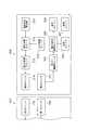
図6は、本発明の実施例2におけるカプセル型内視鏡300の機能ブロックを示している。また、図7は、実施例2における体外装置400の機能ブロックを示している。カプセル型内視鏡300と体外装置400とで被検体内情報取得システムを構成している。本実施例において、実施例1と同一の部分には、同一の符号を付し、重複する説明は省略する。 FIG. 6 shows functional blocks of the
本実施例では、カプセル型内視鏡300から体外装置400へ画像データを通信すると共に、さらに体外装置400からカプセル内視鏡300へは電力や制御信号を通信(伝送)している点が実施例1と異なる。 In the present embodiment, image data is communicated from the
本実施例では、カプセル型内視鏡300側に形成された第1のパッド109と、体外装置400側に形成された第2のパッド201とは、静電結合するように対向する位置に配置されている。同様に、カプセル型内視鏡300側に形成された第3のパッド110と、体外装置400側に形成された第4のパッド214とは、静電結合するように対向する位置に配置されている。 In the present embodiment, the
また、本実施例では、図2に示すように、第1のパッド109を構成する導電体の外周に環状の第3のパッド110を構成する導電体を形成している。しかしながら、これに限られず、第1のパッド109と第3のパッド110とを横に並べて配置する等の他の配置構成をとることもできる。 In this embodiment, as shown in FIG. 2, the conductor constituting the annular
さらに、カプセル型内視鏡300側の第1の変調ユニット106と、体外装置400側の第2の変調ユニット213とで、それぞれ異なる変調周波数を用いることで、第1のパッド109と第3のパッド110とを一つのパッドで兼用すること、即ち一つの導電体で済む構成とすることもできる。 Further, the
そして、上記実施例1と同様に、第1のパッド109に信号処理ユニット105の出力を変調した電圧を印加する。これに応じて生ずる第2のパッド201の表面の電位変化から、第1の復調ユニット202は、信号処理ユニット105の出力信号を復調する。これにより、カプセル型内視鏡300から体外装置400への映像信号等の通信(伝送)を行なうことができる。 As in the first embodiment, a voltage obtained by modulating the output of the
次に、体外装置400からカプセル型内視鏡300への信号の通信について説明する。図7において、体外装置400は、電源信号発生器210と、CCD制御ユニット212と、信号多重ユニット211とを備えている。電源信号発生器210は、所定の周波数の電源電圧信号を出力する。CCD制御ユニット212は、CCD103への制御信号、例えば、CCD感度の制御信号等を出力する。 Next, communication of signals from the
信号多重ユニット211は、電源信号発生器210が出力した電圧信号に対して、CCD制御ユニット212が出力したCCD103への制御信号を重畳し出力する。信号多重ユニット211は、第2の変調ユニット213に接続されている。また、第2の変調ユニット213は、第4のパッド214に接続されている。第2の変調ユニット213は、信号多重ユニット211の出力信号を変調して第4のパッド214に電圧印加する。 The
次に、図6に戻って説明を続ける。第3のパッド110は、カプセル型内視鏡300内に設けられている共振ユニット111に接続されている。共振ユニット111は、電気的共振により第3のパッド110の電位変化から第2の変調ユニット213が変調した周波数成分を抽出し出力する。 Next, returning to FIG. The
共振ユニット111は、信号分離ユニット112に接続されている。信号分離ユニット112は、第2の復調ユニット113と第3の復調ユニット114とに接続されている。 The
信号分離ユニット112は、共振ユニット111により抽出し出力した第3のパッド110の電位変化を、電圧信号成分と、CCD103への制御信号成分とに分離する。そして、信号分離ユニット112は、電源電圧信号成分を第2の復調ユニット113へ出力する。また、信号分離ユニット112は、CCD103への制御信号成分を第3の復調ユニット114に出力する。 The
第2の復調ユニット113は、信号分離ユニット112が出力した第3のパッド110の電位変化電圧の信号成分に基づいて、電源信号発生器210が出力した電圧信号を復調する。 The
第2の復調ユニット113は、電源ユニット108に接続されている。電源ユニット108は、第2の復調ユニット113が復調した電圧信号から、システムコントロール回路108を介して、カプセル型内視鏡300内の各ユニット、回路等を動作させるための電源を供給する。 The
このように、第4のパッド214に電源信号発生器210が出力した電圧信号に、CCD制御ユニット212が出力したCCD103へ制御信号を重畳した信号を変調した電圧を印加する。そして、カプセル型内視鏡300側では、これにより生じた第3のパッド110の表面の電位変化から、電源信号発生器210が出力した電圧信号を分離、復調する。これにより、体外装置400からカプセル型内視鏡300へ電力を供給できる。この結果、本実施例の被検体内情報取得システムでは、例えば、電磁誘導による電力供給と比較しても巻線等でシステムを大型化することがない。また、カプセル型内視鏡300に必要な気密かつ水密な構成を実現できる。 In this way, a voltage obtained by modulating a signal obtained by superimposing the control signal on the
さらに、第3の復調ユニット114は、信号分離ユニット112が出力した第3のパッド110の電位電圧変化の信号成分から、CCD制御ユニット212が出力したCCD103の制御信号を復調する。 Further, the
第3の復調ユニット114は、CCD駆動回路104に接続されている。復調されたCCD制御ユニット212からのCCD103への制御信号、例えば、感度制御の指示信号等に基づき、CCD103を駆動する。 The
このように、第4のパッド214に、電源信号発生器210が出力した電圧信号に、CCD制御ユニット212が出力したCCD103への制御信号を重畳した信号を変調した電圧を印加する。そして、カプセル型内視鏡300側では、これにより生じた第3のパッド110の表面の電位変化から、CCD制御ユニット212が出力したCCD103への制御信号を分離、復調する。これにより、体外装置400からカプセル型内視鏡300への信号通信を実現できる。この結果、本実施例の被検体内情報取得システムでは、電波送受信のためのアンテナの設置等でシステムを大型化することがない。また、カプセル型内視鏡300に必要な気密かつ水密な構成を実現できる。 In this manner, a voltage obtained by modulating a signal obtained by superimposing the control signal to the
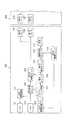
次に、本実施例における上述の信号の流れをフローチャートに基づいて、さらに詳細に説明する。図8、図9は、それぞれ本実施例における信号の流れを示すフローチャートである。 Next, the above-described signal flow in the present embodiment will be described in more detail based on a flowchart. 8 and 9 are flowcharts showing the signal flow in the present embodiment.
ステップS801において、電源信号発生器210は、信号多重ユニット211へ所定の周波数の電源電圧信号を出力する。ステップS802において、CCD制御ユニット212は、信号多重ユニット211に対してCCD103への制御信号を出力する。 In step S <b> 801, the power
ステップS803において、信号多重ユニット211は、電源信号発生器210が出力した電圧信号に、CCD制御ユニット212が出力したCCD103への制御信号を重畳し、第2の変調ユニット213へ出力する。 In step S <b> 803, the
ステップS804において、第2の変調ユニット213は、信号多重ユニット211の出力信号を変調して第4のパッド214へ電圧印加する。ステップS805において、第4のパッド214に印加された信号多重ユニット211の出力信号を変調した電圧により、第3のパッド110の表面の電位が変化する。 In step S804, the
ステップS806において、共振ユニット111は、電気的共振により第3のパッド110の電位変化から第2の変調ユニット213が変調出力した周波数成分を抽出し、信号分離ユニット112に出力する。 In step S806, the
ステップS807において、信号分離ユニット112は、共振ユニット111により抽出した第3のパッド110の電位変化を、電源電圧信号成分とCCD103への制御信号成分とに分離する。 In step S807, the
ステップS808において、信号分離ユニット112は、信号分離ユニット112で分離した電源電圧信号成分を第2の復調ユニット113に出力する。ステップS809において、第2の復調ユニット113は、第3のパッド110の電位変化から、電源信号発生器210が出力した電源電圧信号を復調する。そして、復調された電源電圧信号(電力)は、電源ユニット108を介して、カプセル型内視鏡300内の各ユニット、各回路等に供給される。 In step S <b> 808, the
また、ステップS810において、信号分離ユニット112は、CCD103への制御信号成分を第3の復調ユニット114へ出力する。ステップS811において、第3の復調ユニット114は、第3のパッド110の電位変化から、CCD制御ユニット212が出力したCCD103への制御信号を復調する。そして、第3の復調ユニット114は、CCD駆動回路104に対して復調した制御信号を出力する。 In step S 810, the
次に、図9のステップS812において、CCD駆動回路104がCCD103へ駆動信号を出力する。ステップS813において、CCD103は、生体内情報を取得(撮像)する。そして、CCD103は、取得した生体内情報を信号処理ユニット105へ出力する。 Next, in step S812 in FIG. 9, the
ステップS814において、信号処理ユニット105は、CCD103の出力信号から生体内情報信号を生成する。そして、信号処理ユニット105は、生成した生体内情報信号を第1の変調ユニット106へ出力する。 In step S <b> 814, the
ステップS815において、第1の変調ユニット106は、信号処理ユニット105の出力信号を変調する。そして、第1の変調ユニット106は、変調した出力信号に応じて第1のパッド109に電圧印加する。 In step S815, the
ステップS816において、第1のパッド109に印加された信号処理ユニット105の出力信号を変調した電圧により、第2のパッド201の表面の電位が変化する。ステップS817において、第1の復調ユニット202は、第2のパッド201の表面の電位変化に基づいて、信号処理ユニット105の出力信号を復調する。そして、第1の復調ユニット202は、復調された出力信号を第2の信号処理ユニット203に出力する。 In step S816, the potential of the surface of the
ステップS818において、第2の信号処理ユニット203は、第1の復調ユニット202により復調された信号処理ユニット105の出力信号から、必要な生体内情報を得るための信号処理を行なう。 In step S818, the second
ステップS819において、第2の信号処理ユニット203は、信号処理で得られた生体内情報を表示ユニット204へ出力する。ステップS820において、表示ユニット204は、生体内情報を表示する。 In step S819, the second
ステップS821において、第2の信号処理ユニット203は、信号処理で得られた生体内情報を記録ユニット205へ出力する。ステップS822において、記録ユニット205は、生体内情報を記録、保管する。 In step S821, the second
次に、変調周波数の最適化について説明する。第1の復調ユニット202で復調された第2の信号処理ユニットからの出力信号の状態(S/N比)に基づいて、第1の変調ユニット106が信号処理ユニット105の出力信号を変調して第1のパッド109に電圧印加するときの変調周波数を決定することができる。 Next, the optimization of the modulation frequency will be described. Based on the state (S / N ratio) of the output signal from the second signal processing unit demodulated by the
例えば、第1の変調ユニット106により初期変調周波数を基準にして、初期変調周波数よりも低い側と高い側とに変調周波数を変化させる。初期変調周波数とは、実験等で求めた、一般的に第2の信号処理ユニット203の出力信号の状態が良い周波数を言う。 For example, the
そして、第1の復調ユニット202により復調された第2の信号処理ユニット203の出力信号の状態、例えばS/N等が良くなる周波数を最適周波数として決定する。 Then, the state of the output signal of the second
また、変調周波数の変更は、変更する周波数を無作為に決定することとしても良いが、いわゆる山登り法(最急勾配法)を用いることによっても、より迅速に最適な変調周波数の調整を行なうこととしても良い。この他にも、任意のアルゴリズムを用いて変更する周波数を決定することができる。 The modulation frequency can be changed by randomly determining the frequency to be changed, but the optimum modulation frequency can be adjusted more quickly by using the so-called hill-climbing method (steepest gradient method). It is also good. In addition, the frequency to be changed can be determined using an arbitrary algorithm.
このような、最適周波数決定の手順を図9のフローチャートに基づいて説明する。ステップS817の次に、ステップS823において、第1の復調ユニット202により復調された第2の信号処理ユニット203の出力信号の状態(S/N等)を前回の状態と比較する。今回の状態が前回の状態よりも良いとき、ステップS824において変調周波数を今回の周波数へ変更する。そして、ステップS815へ戻る。前回の状態が今回の状態よりも良いとき、ステップS815へ戻る。このように、図9において、点線で囲んだ部分の手順が変調周波数の最適化手順に相当する。 The procedure for determining the optimum frequency will be described with reference to the flowchart of FIG. Following step S817, in step S823, the state (S / N, etc.) of the output signal of the second
これによれば、生体10の個人差や日時による生体の状態の差等の影響を低減して、カプセル型内視鏡300と体外装置400とのより良好な通信を実現できる。 According to this, the communication between the
また、上記各実施例のカプセル型内視鏡は、LED、CCD等を備えることによって、生体の内部の画像を撮像する構成としている。しかしながら、被検体内に導入される被検体内導入装置は、かかる構成に限定されるものではなく、例えば被検体内の温度情報やpH情報などの他の生体情報を取得するものとしても良い。 In addition, the capsule endoscope of each of the above embodiments is configured to take an image inside the living body by including an LED, a CCD, and the like. However, the intra-subject introduction apparatus to be introduced into the subject is not limited to such a configuration, and other biological information such as temperature information and pH information in the subject may be acquired.
また、本発明は、飲み込み型のカプセル型内視鏡に限られず、一般の体内へ挿入する型の内視鏡に適用することができる。この場合、体内の温度等の情報を本システムにより体外へ容易に通信できると共に、内視鏡の気密性を向上できる。また、本発明は、いわゆる心臓のペースメーカに適用することもできる。例えば、本システムにより、ペースメーカの駆動のための情報を体外からぺースメーカに対して通信できる。さらに、ペースメーカ内に記録されている履歴情報等を装着者に負担を強いることなく体外へ通信できる。 The present invention is not limited to a swallowable capsule endoscope, but can be applied to a general endoscope that is inserted into the body. In this case, information such as the temperature inside the body can be easily communicated outside the body by this system, and the airtightness of the endoscope can be improved. The present invention can also be applied to so-called cardiac pacemakers. For example, the system can communicate information for driving the pacemaker from the outside of the body to the pacemaker. Furthermore, history information and the like recorded in the pacemaker can be communicated outside the body without imposing a burden on the wearer.
また、上記各実施例では、被検体として、生体を検査、観察する例を示している。しかしながら、本発明は、これに限られず、例えば工業用製品を被検体としても良い。 In each of the above embodiments, an example in which a living body is inspected and observed as a subject is shown. However, the present invention is not limited to this. For example, an industrial product may be used as the subject.
以上のように、本発明に被検体内情報取得システムは、小型で、患者(生体)の負担を軽減する場合に有用である。 As described above, the in-subject information acquisition system according to the present invention is small and useful for reducing the burden on the patient (living body).
10 生体
100 カプセル型内視鏡
101 LED
102 LED駆動回路
103 CCD
104 CCD駆動回路
105 第1の信号処理ユニット
106 変調ユニット
107 システムコントロール回路
108 電源ユニット
109 第1のパッド
110 第3のパッド
111 共振ユニット
112 信号分離ユニット
113 第2の復調ユニット
114 第3の復調ユニット
120a 窓
120 外装部
200 体外装置
201 第2のパッド
201a 基材
201b 薄膜
201c 絶縁薄膜
202 (第1の)復調ユニット
203 第2の信号処理ユニット
204 表示ユニット
205 記録ユニット
206 携帯ユニット
207 電源ユニット
210 電源信号発生器
211 信号多重ユニット
212 CCD制御ユニット
213 第2の変調ユニット
214 第4のパッド
300 カプセル型内視鏡
400 体外装置10
102
Claims (7)
Translated fromJapanese前記被検体内導入装置は、少なくとも第1のパッドを備え、
前記体外装置は、少なくとも第2のパッドを備え、
前記第1のパッドと前記第2のパッドとの間で信号の送受信を行うために、前記被検体内導入装置と前記体外装置との少なくともいずれか一方の装置は、いずれか一方の装置の前記パッドに信号を変調して電圧印加する変調手段を備え、
他方の装置は、他方の装置の前記パッドの電位変化から信号復調する復調手段を備えていることを特徴とする被検体内情報取得システム。An in-subject information acquisition system comprising: an in-subject introduction device introduced into a subject; and an extracorporeal device arranged outside the subject and communicating with the in-subject introduction device. ,
The in-subject introduction device includes at least a first pad,
The extracorporeal device comprises at least a second pad;
In order to perform transmission and reception of signals between the first pad and the second pad, at least one of the in-vivo introduction device and the extracorporeal device is the one of the devices. A modulation means for modulating a signal and applying a voltage to the pad;
The other apparatus includes a demodulating means for demodulating a signal from a change in potential of the pad of the other apparatus.
前記体外装置は、前記映像信号を復調することを特徴とする請求項1に記載の被検体内情報取得システム。The in-subject introduction apparatus has an imaging unit that images at least a test site of the subject and outputs at least a video signal;
The in-vivo information acquiring system according to claim 1, wherein the extracorporeal device demodulates the video signal.
前記第1のパッドは、前記カプセル型内視鏡の表面に形成されていることを特徴とする請求項1〜5のいずれか一項に記載の被検体内情報取得システム。The in-subject introduction apparatus is a capsule endoscope including an exterior portion formed in a bottomed cylindrical shape that can be introduced into the subject,
The in-vivo information acquiring system according to any one of claims 1 to 5, wherein the first pad is formed on a surface of the capsule endoscope.
前記体外装置から前記カプセル型内視鏡へ、少なくとも前記カプセル型内視鏡を駆動するための電力が伝送されることを特徴とする請求項6に記載の被検体内情報取得システム。At least a video signal is transmitted from the capsule endoscope to the extracorporeal device,
The in-vivo information acquiring system according to claim 6, wherein at least power for driving the capsule endoscope is transmitted from the extracorporeal device to the capsule endoscope.
Priority Applications (3)
| Application Number | Priority Date | Filing Date | Title |
|---|---|---|---|
| JP2005256262AJP2007068622A (en) | 2005-09-05 | 2005-09-05 | Acquisition system for biological information of subject |
| PCT/JP2006/315988WO2007029453A1 (en) | 2005-09-05 | 2006-08-08 | Intrasubject information acquiring system |
| US11/515,574US20070055098A1 (en) | 2005-09-05 | 2006-09-05 | In-body information acquisition system |
Applications Claiming Priority (1)
| Application Number | Priority Date | Filing Date | Title |
|---|---|---|---|
| JP2005256262AJP2007068622A (en) | 2005-09-05 | 2005-09-05 | Acquisition system for biological information of subject |
Publications (1)
| Publication Number | Publication Date |
|---|---|
| JP2007068622Atrue JP2007068622A (en) | 2007-03-22 |
Family
ID=37830841
Family Applications (1)
| Application Number | Title | Priority Date | Filing Date |
|---|---|---|---|
| JP2005256262AWithdrawnJP2007068622A (en) | 2005-09-05 | 2005-09-05 | Acquisition system for biological information of subject |
Country Status (3)
| Country | Link |
|---|---|
| US (1) | US20070055098A1 (en) |
| JP (1) | JP2007068622A (en) |
| WO (1) | WO2007029453A1 (en) |
Cited By (3)
| Publication number | Priority date | Publication date | Assignee | Title |
|---|---|---|---|---|
| JP2008301967A (en)* | 2007-06-06 | 2008-12-18 | Olympus Corp | Capsule type endoscope apparatus |
| US8480564B2 (en) | 2007-10-01 | 2013-07-09 | Olympus Corporation | Capsule type medical apparatus and capsule type medical system |
| JP2015133125A (en)* | 2009-11-04 | 2015-07-23 | プロテウス デジタル ヘルス, インコーポレイテッド | system for supply chain management |
Families Citing this family (61)
| Publication number | Priority date | Publication date | Assignee | Title |
|---|---|---|---|---|
| US8730031B2 (en) | 2005-04-28 | 2014-05-20 | Proteus Digital Health, Inc. | Communication system using an implantable device |
| US9198608B2 (en) | 2005-04-28 | 2015-12-01 | Proteus Digital Health, Inc. | Communication system incorporated in a container |
| EP3827747A1 (en)* | 2005-04-28 | 2021-06-02 | Otsuka Pharmaceutical Co., Ltd. | Pharma-informatics system |
| US8912908B2 (en) | 2005-04-28 | 2014-12-16 | Proteus Digital Health, Inc. | Communication system with remote activation |
| US8836513B2 (en) | 2006-04-28 | 2014-09-16 | Proteus Digital Health, Inc. | Communication system incorporated in an ingestible product |
| US8802183B2 (en) | 2005-04-28 | 2014-08-12 | Proteus Digital Health, Inc. | Communication system with enhanced partial power source and method of manufacturing same |
| US8547248B2 (en) | 2005-09-01 | 2013-10-01 | Proteus Digital Health, Inc. | Implantable zero-wire communications system |
| JP2009544338A (en) | 2006-05-02 | 2009-12-17 | プロテウス バイオメディカル インコーポレイテッド | Treatment regimen customized to the patient |
| US20080020037A1 (en)* | 2006-07-11 | 2008-01-24 | Robertson Timothy L | Acoustic Pharma-Informatics System |
| EP2087589B1 (en) | 2006-10-17 | 2011-11-23 | Proteus Biomedical, Inc. | Low voltage oscillator for medical devices |
| SG175681A1 (en) | 2006-10-25 | 2011-11-28 | Proteus Biomedical Inc | Controlled activation ingestible identifier |
| US8718193B2 (en) | 2006-11-20 | 2014-05-06 | Proteus Digital Health, Inc. | Active signal processing personal health signal receivers |
| CN101686800A (en) | 2007-02-01 | 2010-03-31 | 普罗秋斯生物医学公司 | Ingestible Event Marker System |
| US8956288B2 (en) | 2007-02-14 | 2015-02-17 | Proteus Digital Health, Inc. | In-body power source having high surface area electrode |
| EP2124725A1 (en) | 2007-03-09 | 2009-12-02 | Proteus Biomedical, Inc. | In-body device having a multi-directional transmitter |
| EP2063771A1 (en) | 2007-03-09 | 2009-06-03 | Proteus Biomedical, Inc. | In-body device having a deployable antenna |
| US8115618B2 (en) | 2007-05-24 | 2012-02-14 | Proteus Biomedical, Inc. | RFID antenna for in-body device |
| DK2192946T3 (en) | 2007-09-25 | 2022-11-21 | Otsuka Pharma Co Ltd | In-body device with virtual dipole signal amplification |
| JP4937874B2 (en)* | 2007-10-01 | 2012-05-23 | オリンパス株式会社 | In-subject information acquisition system |
| JP4934609B2 (en)* | 2008-02-13 | 2012-05-16 | オリンパス株式会社 | Capsule type medical device and capsule type medical system |
| KR101586193B1 (en) | 2007-11-27 | 2016-01-18 | 프로테우스 디지털 헬스, 인코포레이티드 | Transbody communication systems employing communication channels |
| CN104376659B (en) | 2008-03-05 | 2019-10-25 | 普罗透斯数字保健公司 | The ingestible event flag of multi-modal communications and system, and the method using it |
| AU2009268827B2 (en) | 2008-07-08 | 2013-10-24 | Proteus Digital Health, Inc. | Ingestible event marker data framework |
| MY154217A (en) | 2008-08-13 | 2015-05-15 | Proteus Digital Health Inc | Ingestible circuitry |
| US8036748B2 (en) | 2008-11-13 | 2011-10-11 | Proteus Biomedical, Inc. | Ingestible therapy activator system and method |
| EP2358270A4 (en) | 2008-12-11 | 2014-08-13 | Proteus Digital Health Inc | Evaluation of gastrointestinal function using portable electroviscerography systems and methods of using the same |
| US9439566B2 (en) | 2008-12-15 | 2016-09-13 | Proteus Digital Health, Inc. | Re-wearable wireless device |
| US9659423B2 (en) | 2008-12-15 | 2017-05-23 | Proteus Digital Health, Inc. | Personal authentication apparatus system and method |
| TWI503101B (en) | 2008-12-15 | 2015-10-11 | Proteus Digital Health Inc | Body-associated receiver and method |
| SG172847A1 (en) | 2009-01-06 | 2011-08-29 | Proteus Biomedical Inc | Pharmaceutical dosages delivery system |
| KR20110103446A (en) | 2009-01-06 | 2011-09-20 | 프로테우스 바이오메디컬, 인코포레이티드 | Intake-Related Biofeedback and Individualized Medical Treatment Methods and Systems |
| WO2010111403A2 (en) | 2009-03-25 | 2010-09-30 | Proteus Biomedical, Inc. | Probablistic pharmacokinetic and pharmacodynamic modeling |
| JP5284846B2 (en)* | 2009-03-30 | 2013-09-11 | オリンパス株式会社 | In vivo observation system and method of operating the in vivo observation system |
| JP2010240104A (en)* | 2009-04-03 | 2010-10-28 | Olympus Corp | In-vivo observation system and method for driving in-vivo observation system |
| EP3906845A1 (en) | 2009-04-28 | 2021-11-10 | Otsuka Pharmaceutical Co., Ltd. | Highly reliable ingestible event markers |
| EP2432458A4 (en) | 2009-05-12 | 2014-02-12 | Proteus Digital Health Inc | Ingestible event markers comprising an ingestible component |
| US8558563B2 (en) | 2009-08-21 | 2013-10-15 | Proteus Digital Health, Inc. | Apparatus and method for measuring biochemical parameters |
| UA109424C2 (en) | 2009-12-02 | 2015-08-25 | PHARMACEUTICAL PRODUCT, PHARMACEUTICAL TABLE WITH ELECTRONIC MARKER AND METHOD OF MANUFACTURING PHARMACEUTICAL TABLETS | |
| US8617088B2 (en)* | 2010-01-29 | 2013-12-31 | St. Jude Medical Systems Ab | Medical guide wire assembly |
| BR112012019212A2 (en) | 2010-02-01 | 2017-06-13 | Proteus Digital Health Inc | data collection system |
| WO2011127252A2 (en) | 2010-04-07 | 2011-10-13 | Proteus Biomedical, Inc. | Miniature ingestible device |
| TWI557672B (en) | 2010-05-19 | 2016-11-11 | 波提亞斯數位康健公司 | Computer system and computer-implemented method to track medication from manufacturer to a patient, apparatus and method for confirming delivery of medication to a patient, patient interface device |
| JP2014504902A (en) | 2010-11-22 | 2014-02-27 | プロテウス デジタル ヘルス, インコーポレイテッド | Ingestible device with medicinal product |
| WO2012125425A2 (en) | 2011-03-11 | 2012-09-20 | Proteus Biomedical, Inc. | Wearable personal body associated device with various physical configurations |
| US9756874B2 (en) | 2011-07-11 | 2017-09-12 | Proteus Digital Health, Inc. | Masticable ingestible product and communication system therefor |
| WO2015112603A1 (en) | 2014-01-21 | 2015-07-30 | Proteus Digital Health, Inc. | Masticable ingestible product and communication system therefor |
| PH12014500174A1 (en) | 2011-07-21 | 2024-02-12 | Proteus Digital Health Inc | Mobile communication device, system, and method |
| US9235683B2 (en) | 2011-11-09 | 2016-01-12 | Proteus Digital Health, Inc. | Apparatus, system, and method for managing adherence to a regimen |
| EP2874886B1 (en) | 2012-07-23 | 2023-12-20 | Otsuka Pharmaceutical Co., Ltd. | Techniques for manufacturing ingestible event markers comprising an ingestible component |
| AU2013331417B2 (en) | 2012-10-18 | 2016-06-02 | Proteus Digital Health, Inc. | Apparatus, system, and method to adaptively optimize power dissipation and broadcast power in a power source for a communication device |
| US11149123B2 (en) | 2013-01-29 | 2021-10-19 | Otsuka Pharmaceutical Co., Ltd. | Highly-swellable polymeric films and compositions comprising the same |
| JP6498177B2 (en) | 2013-03-15 | 2019-04-10 | プロテウス デジタル ヘルス, インコーポレイテッド | Identity authentication system and method |
| WO2014144738A1 (en) | 2013-03-15 | 2014-09-18 | Proteus Digital Health, Inc. | Metal detector apparatus, system, and method |
| EP3005281A4 (en) | 2013-06-04 | 2017-06-28 | Proteus Digital Health, Inc. | System, apparatus and methods for data collection and assessing outcomes |
| US9796576B2 (en) | 2013-08-30 | 2017-10-24 | Proteus Digital Health, Inc. | Container with electronically controlled interlock |
| CA2965941C (en) | 2013-09-20 | 2020-01-28 | Proteus Digital Health, Inc. | Methods, devices and systems for receiving and decoding a signal in the presence of noise using slices and warping |
| WO2015044722A1 (en) | 2013-09-24 | 2015-04-02 | Proteus Digital Health, Inc. | Method and apparatus for use with received electromagnetic signal at a frequency not known exactly in advance |
| US10084880B2 (en) | 2013-11-04 | 2018-09-25 | Proteus Digital Health, Inc. | Social media networking based on physiologic information |
| US11051543B2 (en) | 2015-07-21 | 2021-07-06 | Otsuka Pharmaceutical Co. Ltd. | Alginate on adhesive bilayer laminate film |
| KR20210018961A (en) | 2016-07-22 | 2021-02-18 | 프로테우스 디지털 헬스, 인코포레이티드 | Electromagnetic sensing and detection of ingestible event markers |
| CN109963499B (en) | 2016-10-26 | 2022-02-25 | 大冢制药株式会社 | Method for manufacturing capsules with ingestible event markers |
Family Cites Families (4)
| Publication number | Priority date | Publication date | Assignee | Title |
|---|---|---|---|---|
| IL156876A0 (en)* | 2001-01-11 | 2004-02-08 | Given Imaging Ltd | Device and system for in-vivo procedures |
| US7160258B2 (en)* | 2001-06-26 | 2007-01-09 | Entrack, Inc. | Capsule and method for treating or diagnosing the intestinal tract |
| KR100522132B1 (en)* | 2003-01-25 | 2005-10-18 | 한국과학기술연구원 | Data receiving method and apparatus in human body communication system |
| JP4455067B2 (en)* | 2004-01-14 | 2010-04-21 | オリンパス株式会社 | Capsule endoscope device |
- 2005
- 2005-09-05JPJP2005256262Apatent/JP2007068622A/ennot_activeWithdrawn
- 2006
- 2006-08-08WOPCT/JP2006/315988patent/WO2007029453A1/enactiveApplication Filing
- 2006-09-05USUS11/515,574patent/US20070055098A1/ennot_activeAbandoned
Cited By (3)
| Publication number | Priority date | Publication date | Assignee | Title |
|---|---|---|---|---|
| JP2008301967A (en)* | 2007-06-06 | 2008-12-18 | Olympus Corp | Capsule type endoscope apparatus |
| US8480564B2 (en) | 2007-10-01 | 2013-07-09 | Olympus Corporation | Capsule type medical apparatus and capsule type medical system |
| JP2015133125A (en)* | 2009-11-04 | 2015-07-23 | プロテウス デジタル ヘルス, インコーポレイテッド | system for supply chain management |
Also Published As
| Publication number | Publication date |
|---|---|
| US20070055098A1 (en) | 2007-03-08 |
| WO2007029453A1 (en) | 2007-03-15 |
Similar Documents
| Publication | Publication Date | Title |
|---|---|---|
| JP2007068622A (en) | Acquisition system for biological information of subject | |
| US20070078304A1 (en) | Electronic endoscope system | |
| KR100873683B1 (en) | Human Body Communication Method, Human Body Communication System and Capsule Endoscope | |
| JP5313689B2 (en) | System for determining the position of an in-vivo sensing device and method of operating the system | |
| CN101146476B (en) | In-vivo information acquisition system | |
| JP5466171B2 (en) | Human body communication system and method | |
| US20040171915A1 (en) | Method and apparatus for transmitting non-image information in an in vivo imaging system | |
| US20090177036A1 (en) | In-Body Position Detecting System | |
| EP2011430B1 (en) | Antenna unit and receiving system | |
| EP2174581B1 (en) | Receiving unit | |
| EP2116173A1 (en) | Capsule medical apparatus | |
| EP1800591B1 (en) | Radio intra-subject information acquiring system | |
| US10777881B2 (en) | Receiving antenna, receiving antenna unit, and receiving system | |
| Hayami et al. | Wireless image-data transmission from an implanted image sensor through a living mouse brain by intra body communication | |
| JP4959965B2 (en) | Body cavity introduction device placement system | |
| KR100399572B1 (en) | Bi-directional communication telemetry capsule | |
| WO2007091556A1 (en) | Relay unit | |
| KR100878719B1 (en) | Human Body Communication Method, Human Body Communication System and Capsule Endoscope | |
| JP5389377B2 (en) | Antenna unit | |
| KR20060012755A (en) | Apparatus and method for human communication using magnetic field | |
| JP5622605B2 (en) | Receiver unit | |
| KR20080028854A (en) | Human body communication method, human body communication system and capsule endoscope used therein | |
| WO2018020756A1 (en) | Relaying unit, reception device, and reception system |
Legal Events
| Date | Code | Title | Description |
|---|---|---|---|
| A300 | Application deemed to be withdrawn because no request for examination was validly filed | Free format text:JAPANESE INTERMEDIATE CODE: A300 Effective date:20081202 |