JP2007065995A - Electronics - Google Patents
ElectronicsDownload PDFInfo
- Publication number
- JP2007065995A JP2007065995AJP2005251297AJP2005251297AJP2007065995AJP 2007065995 AJP2007065995 AJP 2007065995AJP 2005251297 AJP2005251297 AJP 2005251297AJP 2005251297 AJP2005251297 AJP 2005251297AJP 2007065995 AJP2007065995 AJP 2007065995A
- Authority
- JP
- Japan
- Prior art keywords
- hinge
- main body
- display device
- state
- display
- Prior art date
- Legal status (The legal status is an assumption and is not a legal conclusion. Google has not performed a legal analysis and makes no representation as to the accuracy of the status listed.)
- Pending
Links
Images


Classifications
- G—PHYSICS
- G06—COMPUTING OR CALCULATING; COUNTING
- G06F—ELECTRIC DIGITAL DATA PROCESSING
- G06F1/00—Details not covered by groups G06F3/00 - G06F13/00 and G06F21/00
- G06F1/16—Constructional details or arrangements
- G06F1/1613—Constructional details or arrangements for portable computers
- G06F1/1615—Constructional details or arrangements for portable computers with several enclosures having relative motions, each enclosure supporting at least one I/O or computing function
- G06F1/1616—Constructional details or arrangements for portable computers with several enclosures having relative motions, each enclosure supporting at least one I/O or computing function with folding flat displays, e.g. laptop computers or notebooks having a clamshell configuration, with body parts pivoting to an open position around an axis parallel to the plane they define in closed position
- G06F1/162—Constructional details or arrangements for portable computers with several enclosures having relative motions, each enclosure supporting at least one I/O or computing function with folding flat displays, e.g. laptop computers or notebooks having a clamshell configuration, with body parts pivoting to an open position around an axis parallel to the plane they define in closed position changing, e.g. reversing, the face orientation of the screen with a two degrees of freedom mechanism, e.g. for folding into tablet PC like position or orienting towards the direction opposite to the user to show to a second user
- G—PHYSICS
- G06—COMPUTING OR CALCULATING; COUNTING
- G06F—ELECTRIC DIGITAL DATA PROCESSING
- G06F1/00—Details not covered by groups G06F3/00 - G06F13/00 and G06F21/00
- G06F1/16—Constructional details or arrangements
- G06F1/1613—Constructional details or arrangements for portable computers
- G06F1/1633—Constructional details or arrangements of portable computers not specific to the type of enclosures covered by groups G06F1/1615 - G06F1/1626
- G06F1/1675—Miscellaneous details related to the relative movement between the different enclosures or enclosure parts
- G06F1/1677—Miscellaneous details related to the relative movement between the different enclosures or enclosure parts for detecting open or closed state or particular intermediate positions assumed by movable parts of the enclosure, e.g. detection of display lid position with respect to main body in a laptop, detection of opening of the cover of battery compartment
- G—PHYSICS
- G06—COMPUTING OR CALCULATING; COUNTING
- G06F—ELECTRIC DIGITAL DATA PROCESSING
- G06F1/00—Details not covered by groups G06F3/00 - G06F13/00 and G06F21/00
- G06F1/16—Constructional details or arrangements
- G06F1/1613—Constructional details or arrangements for portable computers
- G06F1/1633—Constructional details or arrangements of portable computers not specific to the type of enclosures covered by groups G06F1/1615 - G06F1/1626
- G06F1/1675—Miscellaneous details related to the relative movement between the different enclosures or enclosure parts
- G06F1/1683—Miscellaneous details related to the relative movement between the different enclosures or enclosure parts for the transmission of signal or power between the different housings, e.g. details of wired or wireless communication, passage of cabling
Landscapes
- Engineering & Computer Science (AREA)
- Computer Hardware Design (AREA)
- Theoretical Computer Science (AREA)
- Physics & Mathematics (AREA)
- Human Computer Interaction (AREA)
- General Engineering & Computer Science (AREA)
- General Physics & Mathematics (AREA)
- Mathematical Physics (AREA)
- Computer Networks & Wireless Communication (AREA)
- Telephone Set Structure (AREA)
Abstract
Translated fromJapaneseDescription
Translated fromJapanese本発明は、本体と表示部とがヒンジで連結されており、表示部の表示画面を本体に対して伏せた状態と仰向けにした状態とに反転できる機構を備える電子機器に関する。 The present invention relates to an electronic apparatus having a mechanism in which a main body and a display unit are connected by a hinge, and a display screen of the display unit can be inverted between a state where the display screen is turned down and a state where the display unit is turned upside down.
キーボードが上面に露出する本体と、表示装置を内蔵する表示部とを備える携帯型コンピュータが特許文献1に開示されている。本体と表示部とは、利用者側から見て後部側においてヒンジで連結されている。特許文献1に記載の携帯型コンピュータは、表示装置の表示画面を本体のキーボードに対して反転させる機構をさらに有している。 A portable computer including a main body with a keyboard exposed on the upper surface and a display unit with a built-in display device is disclosed in
また、ポータブルコンピュータの操作を補助する入力手段として、キーボード以外の操作手段を備える情報処理装置が特許文献2に開示されている。この情報処理装置は、回転型エンコーダ部とプッシュスイッチ部とで構成されるジョグダイヤルを本体または表示部に備える。
特許文献1に記載された携帯型コンピュータの場合、表示面が外部に露出する位置にして表示ユニットを本体に重ね合わせると、キーボードからの入力を行うことができず、表示画面に設けられるタッチパネルや外部接続されるキーパッドまたはジョイスティックで行わなければならない。 In the case of the portable computer described in
特許文献2に記載された情報処理装置の場合、表示部に設けられたジョグダイヤルは、表示部の外周縁側に露出している。このジョグダイヤルは、ジョグダイヤルの回動軸に向かって一方向から押さえるように操作される。したがって、このジョグダイヤルを操作する場合、表示部がぐらつかないように、操作する指に対して残りの指で表示部を押さえるか、あるいはもう一方の手で表示部を押さえて、操作しなければならない。本体にジョグダイヤルを設けた情報処理装置は、表示部の角度に対してジョグダイヤルの回動軌道面が一致しておらず、また、表示部から離れている。このため、表示された見た目に対して、ジョグダイヤルを操作する感覚にずれが生じる。 In the case of the information processing apparatus described in
そして、表示部の表示面を本体に対して立て起した状態、および、表示面を外に向けて本体に重ね合された状態のいずれの場合にも、表示部に表示された情報を操作するために設けられた操作部を有する電子機器はない。 The information displayed on the display unit is manipulated in both the state where the display surface of the display unit is raised from the main body and the state where the display surface is superimposed on the main body with the display surface facing outward. There is no electronic device having an operation unit provided for the purpose.
本発明は、表示部に表示された見た目に則した操作が行える操作性に優れた操作部を備える電子機器を提供する。 The present invention provides an electronic apparatus including an operation unit with excellent operability that can perform an operation in accordance with an appearance displayed on a display unit.
本発明に係る電子機器は、本体と表示装置と反転ヒンジと支持ユニットと回動ヒンジと操作装置をと備える。本体は、上面にキーボードが露出する。表示装置は、表示面を有し第1の状態と第2の状態と第3の状態に移動する。第1の状態では、表示装置は、表示面をキーボードに向けて本体に重ね合わされる。第2の状態では、表示装置は、本体に対して立てられる。第3の状態において、表示装置は、表示面をキーボードに対して反対に向けて本体に重ね合わされる。反転ヒンジは、表示装置を第1の状態から第3の状態へ反転軸を中心に回動させる。支持ユニットは、反転ヒンジで表示装置と連結される。回動ヒンジは、本体と支持ユニットとを連結し、本体の後側に沿って設けられる回動軸を中心に支持ユニットを回動させる。操作装置は、反転軸と同軸上に支持ユニットに設けられ、表示装置に表示される情報に関連付けられる信号を出力する。 An electronic apparatus according to the present invention includes a main body, a display device, a reverse hinge, a support unit, a rotating hinge, and an operation device. The main body has a keyboard exposed on the top surface. The display device has a display surface and moves to a first state, a second state, and a third state. In the first state, the display device is superimposed on the main body with the display surface facing the keyboard. In the second state, the display device is stood with respect to the main body. In the third state, the display device is superimposed on the main body with the display surface facing away from the keyboard. The reversing hinge rotates the display device from the first state to the third state around the reversing axis. The support unit is connected to the display device by an inversion hinge. The rotation hinge connects the main body and the support unit, and rotates the support unit around a rotation axis provided along the rear side of the main body. The operating device is provided in the support unit on the same axis as the reversing axis, and outputs a signal associated with information displayed on the display device.
本発明の電子機器は、操作装置を表示装置の反転軸と同軸上に配置しているので、表示装置に表示された情報に対して感覚的に操作しやすい。 In the electronic apparatus of the present invention, since the operation device is arranged coaxially with the reversing axis of the display device, the information displayed on the display device can be easily operated sensuously.
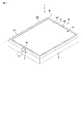
本発明に係る第1の実施形態の電子機器を図1から図6を参照して説明する。図1に示す電子機器1は、本体2と表示装置3と反転ヒンジと支持ユニット5と回動ヒンジと操作装置7とを備える。以降、説明の都合上、電子機器を利用する側から見て、右側、左側、上、下、および、利用者に近い側を前、利用者から離れた側を後と定義する。 An electronic apparatus according to a first embodiment of the present invention will be described with reference to FIGS. An
本体2は、上面にキーボード8が露出している。表示装置3は、表示ユニット31とタッチパネル32と保持カバー33とを有している。表示ユニット31は、例えば、液晶ディスプレイ、プラズマディスプレイ、有機エレクトリックルミネッセンスディスプレイ、表面電界ディスプレイを用いる。タッチパネル32は、表示ユニット31の表示面311に重ねて取り付けられ、表示される情報に振れることで入力を行える。 The
反転ヒンジは、表示装置3を挟んで一対となる第1の反転ヒンジ41と第2の反転ヒンジ42とで構成される。第1の反転ヒンジ41は、表示装置3の左側に配置され、第2の反転ヒンジ42は、表示装置3の右側に配置されている。 The reversing hinge includes a
表示装置3は、第1の反転ヒンジ41と第2の反転ヒンジ42によって支持ユニット5と連結されている。表示装置3は、第1の反転ヒンジ41および第2の反転ヒンジ42によって、表示面311に沿って水平方向に設定される反転軸Aを中心に、図3に示すように回動される。反転軸Aは、表示面311を上下に等しく二分割する表示装置3の中心を通り水平に配置される。 The
回動ヒンジは、表示装置3の幅方向に一対となる第1の回動ヒンジ61と第2の回動ヒンジ62とで構成されている。第1の回動ヒンジ61は、本体2の後側左寄りに配置され、第2の回動ヒンジ62は、本体2の後側右寄りに配置されている。 The rotating hinge includes a first
支持ユニット5は、第1の回動ヒンジ61と第2の回動ヒンジ62とによって本体2と連結されている。支持ユニット5は、第1の回動ヒンジ61および第2の回動ヒンジ62によって、本体2の後部に沿って水平方向へ設定される回動軸Bを中心に本体2に対して回動する。支持ユニット5は、表示装置3の外周を囲い、本体2とほぼ同じ外周の枠形に形成されている。反転軸Aと回動軸Bは、本実施形態において互に平行に配置されている。 The
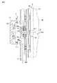
操作装置7は、図1に示すように第1の反転ヒンジ41と同じく支持ユニット5の左側に、支持ユニット5から突出して設けられている。操作装置7は、図5に示すように、摘み部71と、ダイヤル検出スイッチ72と、押ボタンスイッチ73と、スプリングワッシャ74と反転検出スイッチ75a,75bとを備える。 As shown in FIG. 1, the
摘み部71は、キノコ状に形成され、中心軸が反転軸Aと同軸に配置されて、反転軸Aを中心に回転するとともに、反転軸Aに沿って移動する。摘み部71は、内周面に内輪歯車711が形成されている。この内輪歯車711は、ダイヤル検出スイッチ72と係合している。ダイヤル検出スイッチ72は、摘み部71が回転することにより、内輪歯車711の凹凸を検出し、パルス信号を出力する。 The
押ボタンスイッチ73は、摘み部71を反転軸Aに沿って表示装置3側に押し込むと、摘み部71の内面と接触するように配置されている。押ボタンスイッチ73は、摘み部71が接触したことを検出し、信号を出力する。スプリングワッシャ74は、摘み部71が押ボタンスイッチ73に接触したままにならないようにするために、摘み部71を反転軸Aに沿って押し戻す。 The
反転検出スイッチ75a,75bは、第1の反転ヒンジ41に面して配置されている。第1の反転ヒンジ41は、表示装置3にともなって回動する反転シャフト411を有している。支持ユニット5側に延びた反転シャフト411は、先端にストライカ412が固定されている。ストライカ412は、表示装置3が第1の状態となる位置で、反転検出スイッチ75aと当り、表示装置3が第3の状態となる位置で、反転検出スイッチ75bと当たる。 The
ダイヤル検出スイッチ72、押ボタンスイッチ73、反転検出スイッチ75a,75bの信号ケーブルW1は、第1の回動ヒンジを通って本体2の内部に導かれる。なお、ダイヤル検出スイッチ72、押ボタンスイッチ73、反転検出スイッチ75a,75bは、接触式のスイッチに限らず、光学式センサ、磁気式センサ、圧電素子、ストレインゲージなどを用いても良い。 The signal cable W1 of the dial detection switch 72, the
また、第2の反転ヒンジ42は、第1の反転ヒンジ41と同じ構造を有している。ただし、図6に示すように、反転シャフト421は、反転軸Aに沿って同軸上にケーブル送通孔422が設けられている。表示装置3の信号ケーブルW2は、このケーブル送通孔422を介して支持ユニット5に導出される。したがって、表示装置3が支持ユニット5に対して180°反転させても信号ケーブルW2に大きな負荷がかかることがない。表示装置3の信号ケーブルW2は、第2の反転ヒンジ42と第2の回動ヒンジ62を通って本体2の内部に導かれている。 The
なお、第1の反転ヒンジ41と第2の反転ヒンジ42は、表示装置3を支持する上で、十分な剛性および安定性が得られるのであれば、どちらか一方のみが反転軸A周りに表示装置を保持するための摩擦抵抗を有した片持ちの反転ヒンジであっても良い。 Note that only one of the first reversing
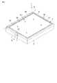
また、第1の反転ヒンジ41および第2の反転ヒンジ42が内蔵される部分の支持ユニット5は、図1から図4に示すように、表示装置3の厚みよりも大きい外形を有しており、両側に膨らんでいる。本体2は、支持ユニット5が重ね合された状態で、支持ユニット5の膨らみに沿う凹部21を有している。 In addition, the
以上のように構成された電子機器1は、反転ヒンジと回動ヒンジを備えることによって、表示装置3を図2に示す第1の状態と、図1に示す第2の状態と、図4に示す第3の状態とに移動する。第1の状態では、表示装置3は、表示面311をキーボード8に向けて重ね合されている。したがって、第1の状態において、電子機器は、使用されない、いわゆる閉状態である。第2の状態では、表示装置3は、本体2に対してたて起された状態である。したがって、第2の状態において、電子機器1は、主にキーボード8で操作される、いわゆるキー入力状態である。第3の状態では、表示装置3は、表示面311をキーボード8に対して反対に向けて本体に重ね合わされている。したがって、第3の状態において、電子機器1は、主に表示装置3に取り付けられたタッチパネル32を用いて操作される、いわゆるタブレット入力状態である。 The
また、第2の状態および第3の状態において、電子機器1は、インストールされたアプリケーションによって表示装置3に表示される情報を、操作装置7から出力される信号を基に操作することができるように構成されている。摘み部71を回転させることによってダイヤル検出スイッチ72から出力される信号と、摘み部71を反転軸Aに沿って押し込むことで押ボタンスイッチ73から出力される信号とを組合せて、より複雑な操作を可能にする。 In the second state and the third state, the
特に、摘み部71を回転させることによってダイヤル検出スイッチ72から出力される信号は、利用者が摘み部71を捻る動作に則した操作に対応させる。このようにすることで、利用者にとって、操作装置7を感覚的に操作することができるため、操作性が向上する。具体的には、表示された図柄や文字列を回転方向に合わせてスクロールさせたり、表示されているランチャーのアプリケーションを切換えたり、画面の輝度やスピーカの音量を変化させたり、選択した画像を拡大または縮小したり、することに、信号の出力を割り当てるとよい。 In particular, a signal output from the dial detection switch 72 by rotating the
また、摘み部71を押し込むことによって押ボタンスイッチ73から出力される信号は、つまみ部71を回転させることによって選択されたり調整されたりしたものをさらに決定する、あるいは、短時間に2回連続して操作することによって一つ前に決定した操作を取り消すなど、の動作に割り当てると良い。 Further, the signal output from the
操作装置7が支持ユニット5よりも外側に突出しているので、表示装置3が第2の状態にある場合に限らず、第3の状態にある場合にも同様に操作することができる。特に、第3の状態においては、表示装置3によってキーボード8が覆い隠されているため、操作装置7が利用できることは、都合が良い。 Since the
また、操作装置7が支持ユニット5よりも突出していることにより、利用者は、親指と人差指とで反転軸Aを挟む両側から摘み部71を摘むことができる。つまり、支持ユニット5が本体2に対してどのような角度に回動していても、操作装置7を操作することに関する操作性が変わることがなく、安定した操作性が得られる。 Further, since the
本実施形態の電子機器1において、第2の状態における表示装置3の左側に操作装置7は、配置されている。これに対して、右側に操作装置7を配置しても良い。この場合、第1の反転ヒンジ41を右側に、第2の反転ヒンジ42を左側に設ける。表示装置3の信号ケーブルW2は、表示装置3を挟んで操作装置7と反対側に設けられる第2の反転ヒンジ42と同じくケーブル送通孔422を有した反転ヒンジを介して導出される。 In the
次に、本発明に係る第2の実施形態の電子機器1Aを図7から図10を参照して説明する。なお、第1の実施形態と同じ機能を有する構成については、同一の符号を付してその説明を省略する。また、第1の反転ヒンジ41および第2の反転ヒンジ、操作装置7の断面構造は、第1の実施形態で説明したとおりであるので、図5および図6ならびにこれに付随する説明を参照するものとし、ここでの説明を省略する。 Next, an
電子機器1Aは、反転軸Aが回動軸Bに対して直交する方向に配置されている。したがって、図8に示すように第1の状態において、第1の反転ヒンジ41は、前側に設けられ、第2の反転ヒンジ42は、後ろ側に設けられている。第1の反転ヒンジ41が設けられる位置、および第2の反転ヒンジ42が設けられる位置に対応して、凹部21が本体2の上部に設けられている。 In the
この電子機器1Aにおいて、図8に示す第1の状態と、図7に示す第2の状態と、図10に示す第3の状態とに、表示装置3が移動する。表示装置3は、第1の状態と第3の状態とにするために、図9に示すように第2の状態の時に、第1の反転ヒンジ41および第2の反転ヒンジ42によって反転軸Aを中心に回転される。 In the
以上のように構成された電子機器1Aは、特に、操作装置7が表示装置3の左右幅方向に中央に配置されているので、左右のどちらの手でも操作装置7を操作しやすい。 In the
第1の実施形態および第2の実施形態において、操作装置7は、ダイヤル検出スイッチ72と押ボタンスイッチ73をと内蔵している他に、反転軸Aに沿って表示装置3から離れる方向へ摘み部71を引っ張る操作を検出する引張検出スイッチを設けても良い。この場合、時計の竜頭のように、一段階あるいは二段階に引き出すように設けてもよい。 In the first embodiment and the second embodiment, the operating
1,1A…電子機器、2…本体、3…表示装置、5…支持ユニット、7…操作装置、8…キーボード、21…凹部、311…表示面、41…第1の反転ヒンジ、42…第2の反転ヒンジ、61…第1の回動ヒンジ、62…第2の回動ヒンジ、A…反転軸、B…回動軸、W1…(操作装置の)信号ケーブル、W2…(表示装置の)信号ケーブル。 DESCRIPTION OF
Claims (8)
Translated fromJapanese表示面を有し、この表示面を前記キーボードに向けて前記本体に重ね合わされる第1の状態と、前記本体に対して立てられた第2の状態と、前記キーボードに対して反対に向けて前記本体に重ね合わされる第3の状態と、に移動する表示装置と、
前記表示装置を前記第1の状態から前記第3の状態へ反転軸を中心に回動させる反転ヒンジと、
前記反転ヒンジによって前記表示装置と連結される支持ユニットと、
前記本体と前記支持ユニットとを連結し、前記本体の後側に沿って設けられる回動軸を中心に前記支持ユニットを回動させる回動ヒンジと、
前記反転軸と同軸上に前記支持ユニットに設けられて、前記表示装置に表示される情報に関連付けられる信号を出力する操作装置と
を備えることを特徴とする電子機器。A main body with a keyboard exposed on the top surface;
A first state in which the display surface is superimposed on the main body with the display surface facing the keyboard; a second state standing with respect to the main body; and an opposite direction with respect to the keyboard A display that moves to a third state superimposed on the body;
A reversing hinge for rotating the display device from the first state to the third state about a reversing axis;
A support unit coupled to the display device by the inversion hinge;
A rotation hinge that connects the main body and the support unit and rotates the support unit around a rotation axis provided along a rear side of the main body;
An electronic device comprising: an operating device that is provided on the support unit and coaxial with the reversal axis and outputs a signal associated with information displayed on the display device.
前記回動ヒンジは、表示装置の幅方向に一対となる第1の回動ヒンジと第2の回動ヒンジとで構成され、
前記操作装置は、前記第1の反転ヒンジと同軸に配置され、
前記操作装置の信号ケーブルは、前記第1の回動ヒンジを通って前記本体内に導かれ、
前記表示装置の信号ケーブルは、前記第2の反転ヒンジおよび前記第2の回動ヒンジを通って前記本体内に導かれる
ことを特徴とする請求項1に記載の電子機器。The reversing hinge is composed of a first reversing hinge and a second reversing hinge that are paired with a display device interposed therebetween.
The rotating hinge is composed of a first rotating hinge and a second rotating hinge that form a pair in the width direction of the display device,
The operating device is disposed coaxially with the first inversion hinge,
The signal cable of the operating device is guided into the main body through the first rotating hinge,
2. The electronic apparatus according to claim 1, wherein a signal cable of the display device is guided into the main body through the second inversion hinge and the second rotating hinge. 3.
前記本体は、前記支持ユニットが重ね合された状態で前記第1の反転ヒンジおよび前記第2の反転ヒンジが内蔵される部分の前記支持ユニットの外形形状に沿う凹部を有する
ことを特徴とする請求項2に記載の電子機器。The portion of the support unit in which the first inversion hinge and the second inversion hinge are incorporated has an outer shape larger than the thickness of the display device,
The said main body has a recessed part which follows the external shape of the said support unit of the part in which the said 1st inversion hinge and the said 2nd inversion hinge are incorporated in the state in which the said support unit was piled up. Item 3. The electronic device according to Item 2.
Priority Applications (2)
| Application Number | Priority Date | Filing Date | Title |
|---|---|---|---|
| JP2005251297AJP2007065995A (en) | 2005-08-31 | 2005-08-31 | Electronics |
| US11/512,041US20070046635A1 (en) | 2005-08-31 | 2006-08-28 | Electronic apparatus |
Applications Claiming Priority (1)
| Application Number | Priority Date | Filing Date | Title |
|---|---|---|---|
| JP2005251297AJP2007065995A (en) | 2005-08-31 | 2005-08-31 | Electronics |
Publications (1)
| Publication Number | Publication Date |
|---|---|
| JP2007065995Atrue JP2007065995A (en) | 2007-03-15 |
Family
ID=37803420
Family Applications (1)
| Application Number | Title | Priority Date | Filing Date |
|---|---|---|---|
| JP2005251297APendingJP2007065995A (en) | 2005-08-31 | 2005-08-31 | Electronics |
Country Status (2)
| Country | Link |
|---|---|
| US (1) | US20070046635A1 (en) |
| JP (1) | JP2007065995A (en) |
Cited By (1)
| Publication number | Priority date | Publication date | Assignee | Title |
|---|---|---|---|---|
| WO2014105238A1 (en)* | 2012-12-28 | 2014-07-03 | Intel Corporation | Electronic device having a base in the form of an outer support frame |
Families Citing this family (19)
| Publication number | Priority date | Publication date | Assignee | Title |
|---|---|---|---|---|
| US7469381B2 (en) | 2007-01-07 | 2008-12-23 | Apple Inc. | List scrolling and document translation, scaling, and rotation on a touch-screen display |
| GB201009952D0 (en)* | 2010-05-11 | 2010-07-21 | Hu Do Ltd | Hinge development |
| US10691230B2 (en)* | 2012-12-29 | 2020-06-23 | Apple Inc. | Crown input for a wearable electronic device |
| ES1078560Y (en)* | 2013-01-18 | 2013-05-07 | Albiral Display Solutions Sl | SET OF DISPLAY AND KEYBOARD KEYBOARD FOR TABLES |
| US12287962B2 (en) | 2013-09-03 | 2025-04-29 | Apple Inc. | User interface for manipulating user interface objects |
| CN110795005A (en) | 2013-09-03 | 2020-02-14 | 苹果公司 | User interface for manipulating user interface objects using magnetic properties |
| US10503388B2 (en)* | 2013-09-03 | 2019-12-10 | Apple Inc. | Crown input for a wearable electronic device |
| US10545657B2 (en) | 2013-09-03 | 2020-01-28 | Apple Inc. | User interface for manipulating user interface objects |
| US11068128B2 (en) | 2013-09-03 | 2021-07-20 | Apple Inc. | User interface object manipulations in a user interface |
| EP3147747A1 (en) | 2014-06-27 | 2017-03-29 | Apple Inc. | Manipulation of calendar application in device with touch screen |
| TWI582641B (en) | 2014-09-02 | 2017-05-11 | 蘋果公司 | Button functionality |
| CN106797493A (en) | 2014-09-02 | 2017-05-31 | 苹果公司 | Music user interface |
| TWI676127B (en) | 2014-09-02 | 2019-11-01 | 美商蘋果公司 | Method, system, electronic device and computer-readable storage medium regarding electronic mail user interface |
| US20160062571A1 (en) | 2014-09-02 | 2016-03-03 | Apple Inc. | Reduced size user interface |
| US10365807B2 (en) | 2015-03-02 | 2019-07-30 | Apple Inc. | Control of system zoom magnification using a rotatable input mechanism |
| US11216027B1 (en)* | 2018-08-07 | 2022-01-04 | Anthony R. Montuya | Rotatable display screen for a notebook computer |
| US10712824B2 (en) | 2018-09-11 | 2020-07-14 | Apple Inc. | Content-based tactile outputs |
| US11435830B2 (en) | 2018-09-11 | 2022-09-06 | Apple Inc. | Content-based tactile outputs |
| CN114063532B (en)* | 2021-11-29 | 2024-04-12 | 中国电子科技集团公司第二十八研究所 | An intelligent control console based on human factors engineering |
Family Cites Families (2)
| Publication number | Priority date | Publication date | Assignee | Title |
|---|---|---|---|---|
| US6005767A (en)* | 1997-11-14 | 1999-12-21 | Vadem | Portable computer having articulated display |
| US20050063145A1 (en)* | 2003-09-18 | 2005-03-24 | Homer Steven S. | Computer system with rotatable display |
- 2005
- 2005-08-31JPJP2005251297Apatent/JP2007065995A/enactivePending
- 2006
- 2006-08-28USUS11/512,041patent/US20070046635A1/ennot_activeAbandoned
Cited By (2)
| Publication number | Priority date | Publication date | Assignee | Title |
|---|---|---|---|---|
| WO2014105238A1 (en)* | 2012-12-28 | 2014-07-03 | Intel Corporation | Electronic device having a base in the form of an outer support frame |
| US9110631B2 (en) | 2012-12-28 | 2015-08-18 | Intel Corporation | Electronic device having base in the form of an outer support frame |
Also Published As
| Publication number | Publication date |
|---|---|
| US20070046635A1 (en) | 2007-03-01 |
Similar Documents
| Publication | Publication Date | Title |
|---|---|---|
| JP2007065995A (en) | Electronics | |
| JP4450008B2 (en) | Electronics | |
| US7099708B2 (en) | Foldable/Slidable Function Keyboard for an Electronic Device | |
| JP5343198B2 (en) | Rotary input device and electronic device | |
| JP2007267355A (en) | Case of portable terminal equipment | |
| KR20130099449A (en) | Rotation type touch screen module and portable terminal having the same | |
| JP2008097057A (en) | Information device input device | |
| JP5586826B2 (en) | Portable electronic devices | |
| JP2009239906A (en) | Mobile terminal having moving keypad | |
| JP2006331287A (en) | Electronics | |
| JP2001298514A (en) | Foldable portable communication machine | |
| JP5269859B2 (en) | Display device and electronic device | |
| JP5610504B2 (en) | Rotary input device and electronic device | |
| JP4657171B2 (en) | Portable electronic device and control method thereof | |
| JP2004240495A (en) | Information processing equipment | |
| JP2000299727A (en) | Communication apparatus and portable radio communication apparatus | |
| JP2004185164A (en) | Portable electronic equipment | |
| JP2004164518A (en) | Information processing equipment | |
| JP2008054035A (en) | Portable electronic device and control method thereof | |
| JP2006023915A (en) | Information input device | |
| JP3616538B2 (en) | Input device | |
| JP2003005863A (en) | Personal digital assistant | |
| KR100693160B1 (en) | Handheld terminal | |
| CN101742861B (en) | Portable electronic device architecture with multiple modes of operation | |
| JP2002032190A (en) | Pointing device |