JP2007059596A - Semiconductor device - Google Patents
Semiconductor deviceDownload PDFInfo
- Publication number
- JP2007059596A JP2007059596AJP2005242641AJP2005242641AJP2007059596AJP 2007059596 AJP2007059596 AJP 2007059596AJP 2005242641 AJP2005242641 AJP 2005242641AJP 2005242641 AJP2005242641 AJP 2005242641AJP 2007059596 AJP2007059596 AJP 2007059596A
- Authority
- JP
- Japan
- Prior art keywords
- semiconductor chip
- chip
- dam
- corner
- semiconductor device
- Prior art date
- Legal status (The legal status is an assumption and is not a legal conclusion. Google has not performed a legal analysis and makes no representation as to the accuracy of the status listed.)
- Granted
Links
- 239000004065semiconductorSubstances0.000titleclaimsabstractdescription78
- 229910000679solderInorganic materials0.000claimsabstractdescription46
- 239000000758substrateSubstances0.000claimsabstractdescription21
- 239000011347resinSubstances0.000description4
- 229920005989resinPolymers0.000description4
- 238000013508migrationMethods0.000description3
- 230000005012migrationEffects0.000description3
- 230000007547defectEffects0.000description2
- WABPQHHGFIMREM-UHFFFAOYSA-Nlead(0)Chemical compound[Pb]WABPQHHGFIMREM-UHFFFAOYSA-N0.000description2
- 239000000463materialSubstances0.000description2
- 238000000034methodMethods0.000description2
- 230000002093peripheral effectEffects0.000description2
- 238000007789sealingMethods0.000description2
- 238000010521absorption reactionMethods0.000description1
- 230000002411adverseEffects0.000description1
- 230000015572biosynthetic processEffects0.000description1
- 238000007796conventional methodMethods0.000description1
- 230000000694effectsEffects0.000description1
- 230000001788irregularEffects0.000description1
- 230000002250progressing effectEffects0.000description1
- 230000003014reinforcing effectEffects0.000description1
Images


Classifications
- H—ELECTRICITY
- H01—ELECTRIC ELEMENTS
- H01L—SEMICONDUCTOR DEVICES NOT COVERED BY CLASS H10
- H01L21/00—Processes or apparatus adapted for the manufacture or treatment of semiconductor or solid state devices or of parts thereof
- H01L21/02—Manufacture or treatment of semiconductor devices or of parts thereof
- H01L21/04—Manufacture or treatment of semiconductor devices or of parts thereof the devices having potential barriers, e.g. a PN junction, depletion layer or carrier concentration layer
- H01L21/50—Assembly of semiconductor devices using processes or apparatus not provided for in a single one of the groups H01L21/18 - H01L21/326 or H10D48/04 - H10D48/07 e.g. sealing of a cap to a base of a container
- H01L21/56—Encapsulations, e.g. encapsulation layers, coatings
- H01L21/563—Encapsulation of active face of flip-chip device, e.g. underfilling or underencapsulation of flip-chip, encapsulation preform on chip or mounting substrate
- H—ELECTRICITY
- H01—ELECTRIC ELEMENTS
- H01L—SEMICONDUCTOR DEVICES NOT COVERED BY CLASS H10
- H01L23/00—Details of semiconductor or other solid state devices
- H01L23/48—Arrangements for conducting electric current to or from the solid state body in operation, e.g. leads, terminal arrangements ; Selection of materials therefor
- H01L23/488—Arrangements for conducting electric current to or from the solid state body in operation, e.g. leads, terminal arrangements ; Selection of materials therefor consisting of soldered or bonded constructions
- H01L23/498—Leads, i.e. metallisations or lead-frames on insulating substrates, e.g. chip carriers
- H01L23/49811—Additional leads joined to the metallisation on the insulating substrate, e.g. pins, bumps, wires, flat leads
- H01L23/49816—Spherical bumps on the substrate for external connection, e.g. ball grid arrays [BGA]
- H—ELECTRICITY
- H01—ELECTRIC ELEMENTS
- H01L—SEMICONDUCTOR DEVICES NOT COVERED BY CLASS H10
- H01L2224/00—Indexing scheme for arrangements for connecting or disconnecting semiconductor or solid-state bodies and methods related thereto as covered by H01L24/00
- H01L2224/73—Means for bonding being of different types provided for in two or more of groups H01L2224/10, H01L2224/18, H01L2224/26, H01L2224/34, H01L2224/42, H01L2224/50, H01L2224/63, H01L2224/71
- H01L2224/732—Location after the connecting process
- H01L2224/73201—Location after the connecting process on the same surface
- H01L2224/73203—Bump and layer connectors
Landscapes
- Engineering & Computer Science (AREA)
- Physics & Mathematics (AREA)
- Condensed Matter Physics & Semiconductors (AREA)
- General Physics & Mathematics (AREA)
- Computer Hardware Design (AREA)
- Microelectronics & Electronic Packaging (AREA)
- Power Engineering (AREA)
- Manufacturing & Machinery (AREA)
- Structures Or Materials For Encapsulating Or Coating Semiconductor Devices Or Solid State Devices (AREA)
- Encapsulation Of And Coatings For Semiconductor Or Solid State Devices (AREA)
- Wire Bonding (AREA)
Abstract
Description
Translated fromJapanese本発明は、基板表面に半導体チップがフリップチップ接続された半導体装置に関する。 The present invention relates to a semiconductor device in which a semiconductor chip is flip-chip connected to a substrate surface.
配線基板上に半導体チップをフリップチップ接続した構造では、チップと基板との接続信頼性を確保するために、チップ・基板間の空隙をアンダーフィル(封止樹脂)で充填して補強する。補強効果を確保するには、アンダーフィルをチップ・基板間から若干周囲へ溢れさせチップを頂上として広がる山裾を形成するように充填を行なう。ただし、高密度実装ではチップ直近に他のデバイスや配線系統が配置されており、溢れ出たアンダーフィルが広範囲に広がって周辺部位に達し電気的な作動に悪影響を及ぼすことがあってはならない。そこで、チップ・基板間から溢れ出たアンダーフィルの流出範囲を制限するために種々の提案がなされている。 In a structure in which a semiconductor chip is flip-chip connected on a wiring substrate, the gap between the chip and the substrate is filled with an underfill (sealing resin) and reinforced in order to ensure connection reliability between the chip and the substrate. In order to secure the reinforcing effect, filling is performed so that the underfill is slightly overflowed from the tip to the substrate to the periphery to form a mountain skirt spreading from the tip to the top. However, in high-density mounting, other devices and wiring systems are arranged in the immediate vicinity of the chip, and the overflowing underfill should spread over a wide area and reach the peripheral part, and the electrical operation should not be adversely affected. In view of this, various proposals have been made to limit the outflow range of the underfill overflowing from between the chip and the substrate.
特許文献1、2には、フリップチップ接続ではなく、ワイヤボンディングを用いた構造ではあるが、封止樹脂(アンダーフィルとは呼ばないが)の流出範囲を制限するために半導体チップを枠状に取り囲むダムが開示されている。ワイヤボンディングを用いた構造であるためフリップチップ接続を用いた構造に比べて一般に配線基板やダムのサイズは大きいが、ダムで樹脂の流出範囲を制限するという基本的な考え方は、両方のチップ接続構造に共通している。 In
流出範囲制限効果を高めるために、特許文献1では立体的に多層に積み重ねたダム、特許文献2では平面的に二重枠としたダムがそれぞれ提案されている。 In order to enhance the effect of limiting the outflow range,
特許文献3には、フリップチップ接続を用いた構造において、アンダーフィルの流出範囲を制限するために、(1)チップ接続領域の周縁から周辺の領域でチップ全周にわたってソルダーレジスト層を本来のソルダーレジスト層より薄くして一段下げた段差構造、(2)チップ接続領域の周辺のソルダーレジスト層にチップ全周を取り囲む溝を形成した構造、(3)チップ接続領域の周辺のソルダーレジスト層上にチップ全周を取り囲む枠状のダムを形成した構造が提案されている。 In
しかし、半導体装置の外形の小型化、薄型化とそれに伴う内部構造の高密度化・微細化が進行しており、上記従来の方法ではアンダーフィルの流出範囲を確実に制限することが困難になってきた。 However, the downsizing and thinning of the outer shape of the semiconductor device and the accompanying increase in the density and miniaturization of the internal structure are progressing, and it is difficult to reliably limit the outflow range of the underfill with the above conventional method. I came.
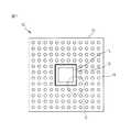
図1に、プリント配線基板12に半導体チップ14をフリップチップ接続した半導体装置10の一部分を模式的に示す。基板12の表面において、アンダーフィル流出範囲制限用の枠状ダム16が半導体チップ14の全周を取り囲み、枠状ダム16の外側に半導体チップ14と外部回路とを配線パターンを介して接続する外部接続端子としてのはんだボール18が配設されている。 FIG. 1 schematically shows a part of a
このように、はんだボール18がチップ14搭載側の基板表面に配置されている場合には、チップ14周辺の直近まではんだボール18が配設されており、ダム16をオーバフローしたアンダーフィル流がはんだボール18に容易に到達する。 As described above, when the
特に、基本設計に対するカスタマイズとして半導体チップのコーナー部直近にはんだボールを増設することがあり、コーナー部では半導体チップ外縁とダム内縁との間隔が狭まるため、チップ・基板間から溢れたアンダーフィル流がダムを越えて外部へオーバフローする危険性が高まる。 In particular, as a customization to the basic design, solder balls may be added in the immediate vicinity of the corner of the semiconductor chip. In the corner, the gap between the outer edge of the semiconductor chip and the inner edge of the dam is narrowed, so an overflow of underfill flows from between the chip and the substrate. The risk of overflowing outside the dam is increased.
図2(1)に、図1の破線円Cで囲んだコーナー部を拡大して示す。半導体チップ14と基板12との間の間隙に充填されたアンダーフィルは同図に20として示すように、半導体チップ14の搭載領域から外に流出するが、アンダーフィルの到達前縁20Fで示した流出範囲は半導体チップ14を取り囲む枠状ダム16の内部に制限されている。 FIG. 2A shows an enlarged view of a corner portion surrounded by a broken-line circle C in FIG. The underfill filled in the gap between the
図2(2)は、カスタマイズとして同じコーナー部にはんだボール18Aを増設した状態を示す。コーナー部では、増設はんだボール18A自体と周囲のクリアランスに要する面積を確保するために、ダム16を半導体チップ14寄りに後退させて設けるため、半導体チップ14の外縁とダム16の内縁との間隔が狭まる。その結果、アンダーフィル20の前縁20Fは破線で示した本来の到達位置20F’より手前のダム16の位置で強制的に堰き止められるため、アンダーフィル20は局所集中して盛り上がり、ダム16を越えてオーバフローする危険性が著しく高まる。 FIG. 2 (2) shows a state where
本発明は、プリント配線基板の同一面に、フリップチップ接続された半導体チップと、この半導体チップ用の外部接続端子としてのはんだボールとが共に配設されている半導体装置において、半導体チップのコーナー部に対面するダムコーナー部でアンダーフィル流のオーバフロー発生を確実に防止した半導体装置を提供することを目的とする。 The present invention relates to a semiconductor device in which a flip chip-connected semiconductor chip and a solder ball as an external connection terminal for the semiconductor chip are disposed on the same surface of a printed wiring board. An object of the present invention is to provide a semiconductor device in which an overflow of an underfill flow is reliably prevented at a dam corner portion facing the surface.
上記の目的を達成するために、本発明の半導体装置は、プリント配線基板の表面に半導体チップがフリップチップ接続された半導体装置であって、
上記基板表面において、アンダーフィル流出範囲制限用の枠状ダムが該半導体チップの全周を取り囲み、該枠状ダムの外側に該半導体チップ用の外部接続端子が配設されており、上記フリップチップ接続箇所および上記外部接続端子配設箇所を除く上記基板表面がソルダーレジスト層で覆われており、
上記半導体チップのコーナー部と、これに対面する上記枠状ダムのコーナー部との間の領域内において、上記ソルダーレジスト層に掘り込みを設けたことを特徴とする。In order to achieve the above object, a semiconductor device of the present invention is a semiconductor device in which a semiconductor chip is flip-chip connected to the surface of a printed wiring board,
On the surface of the substrate, a frame-shaped dam for limiting the underfill outflow range surrounds the entire circumference of the semiconductor chip, and external connection terminals for the semiconductor chip are disposed outside the frame-shaped dam. The substrate surface excluding the connection location and the external connection terminal placement location is covered with a solder resist layer,
The solder resist layer is dug in a region between the corner portion of the semiconductor chip and the corner portion of the frame-shaped dam facing the semiconductor chip.
本発明の半導体装置においては、半導体チップのコーナー部と、これに対面する枠状ダムのコーナー部との間の領域内において、ソルダーレジスト層に設けた掘り込みがアンダーフィル流を吸収するので、ダムを越えてオーバフローすることがない。 In the semiconductor device of the present invention, the digging provided in the solder resist layer absorbs the underfill flow in the region between the corner portion of the semiconductor chip and the corner portion of the frame-shaped dam facing this, There is no overflow beyond the dam.
図3に、本発明による半導体装置の一部分を示す。図3(1)はフリップチップ接続領域のコーナー部の平面図、図3(2)は図3(1)の線A―A’に沿った断面図である。 FIG. 3 shows a part of a semiconductor device according to the present invention. 3A is a plan view of a corner portion of the flip chip connection region, and FIG. 3B is a cross-sectional view taken along line A-A ′ in FIG.
図示した半導体装置50は、プリント配線基板12の表面に半導体チップ14がフリップチップ接続されている。 In the illustrated
基板12の表面において、アンダーフィル流出範囲制限用の枠状ダム16が半導体チップ14の全周を取り囲み、枠状ダム16の外側に半導体チップ14用の外部接続端子としてのはんだボール18Aが配設されており、フリップチップ接続箇所およびはんだボール配設箇所を除く上記基板表面がソルダーレジスト層22で覆われている。はんだボール18Aはパッド部23に接合されている。 On the surface of the
本発明の特徴として、半導体チップ14のコーナー部と、これに対面する枠状ダム16のコーナー部との間の領域内において、ソルダーレジスト層22に掘り込み24を設けた。このコーナー部掘り込み24は、フリップチップ接続するための配線パターンを露出させたソルダーレジスト層の掘り込み(以下、フリップチップ接続部掘り込み)26からダム16の内縁に達するまで直線的な溝状に延在している。すなわち、コーナー部掘り込み24は一端がフリップチップ接続部掘り込み26に接続し、他端がダム16の内縁に接している。 As a feature of the present invention, a digging 24 is provided in the solder resist
アンダーフィル樹脂20は、半導体チップ14と基板12との間隙28を充填した後、半導体チップ14の周囲に溢れ出て、前縁20Fで示されるように半導体チップ14の外縁とダム16との間の領域を外向きに進行する。コーナー部ではアンダーフィル20のかなりの体積が掘り込み24内に収容されるため、アンダーフィル20の上面レベルSが低く抑制され、ダム16で十分に堰き止められて、ダム16を越えてオーバフローすることがない。 The
ここで本発明を適用する半導体装置の各部のサイズの一例を参考までに下記に示す。 An example of the size of each part of the semiconductor device to which the present invention is applied is shown below for reference.
半導体チップ14のサイズ:9.0〜225mm2
ソルダーレジスト層22の厚さ:10〜20μm
半導体チップ14と基板12との間隙28:15〜35μm
(厳密には半導体チップ14とソルダーレジスト層22との間隙)
ダム16:厚さ10〜20μm、幅50〜100μm
フリップチップ接続部掘り込み26の幅W:300〜500μm
一般にダム16は、ソルダーレジスト層22と同様の材質の樹脂で同様の方法により形成するので、厚さもソルダーレジスト層22と同等の10〜20μmとする。ただし、ダム16の材質、形成方法、厚さを上記のように限定する必要はない。Size of semiconductor chip 14: 9.0 to 225 mm2
The thickness of the solder resist layer 22: 10 to 20 μm
The
(Strictly speaking, the gap between the
Dam 16: thickness 10-20 μm, width 50-100 μm
Flip chip connection digging 26 width W: 300-500 μm
In general, the
本発明において、アンダーフィル吸収用の掘り込みを設ける領域を上記コーナー領域に限定した理由を説明する。 In the present invention, the reason why the region where the underfill absorption is provided is limited to the corner region will be described.
前出の特許文献3に記載の従来技術では、半導体チップの周囲全周にソルダーレジスト層に段差や溝を設けている。しかし、ソルダーレジスト層の直下にはフリップチップ接続パッドからの引き出し線(配線パターン)および回路形成のための引き回し線が存在する。そのため、半導体チップの周囲全周にわたってソルダーレジスト層を除去して段差や溝を設けると、この除去部分にフリップチップ接続のリフロー時にはんだが流入し、露出した引き出し線や引き回し線が、はんだ接合されることによる短絡不良が発生する危険性が高まるばかりでなく、はんだ接合時の高温に起因して配線Cuのイオンマイグレーションによる短絡不良の発生の危険性も極端に高まる。特にイオンマイグレーションによる短絡が発生し易くなる。 In the prior art described in
本発明においては、上記のような短絡発生の危険を回避するために、ソルダーレジスト層に掘り込みを形成する領域は、はんだボール増設によるアンダーフィル20のオーバフローが特に発生し易い前記コーナー部のみに限定し、コーナー部以外の領域はソルダーレジスト層を本来の厚さのまま残しておく。 In the present invention, in order to avoid the risk of occurrence of a short circuit as described above, the region where the digging is formed in the solder resist layer is only in the corner portion where the overflow of the
コーナー部掘り込み24の平面形状は、図3に示した溝状に限定する必要はない。 The planar shape of the corner digging 24 need not be limited to the groove shape shown in FIG.
図4に、コーナー部掘り込み24の平面形状の例を示す。なお、図示の便宜上、はんだボール18、18Aは省略してある。 In FIG. 4, the example of the planar shape of the corner part digging 24 is shown. For convenience of illustration, the
図4(1)の例は、図3で説明した溝状の平面形状のコーナー部掘り込み24であり、フリップチップ接続部掘り込み26からダム16まで連続的に延在している。 The example of FIG. 4A is the groove-shaped planar corner digging 24 described in FIG. 3, and extends continuously from the flip chip connection digging 26 to the
図4(2)の例は、半導体チップ14のコーナー付近を「要」とする扇形の平面形状の掘り込み24を示す。この場合も、掘り込み24はフリップチップ接続部掘り込み26からダム16まで連続的に延在している。 The example of FIG. 4B shows a fan-shaped digging 24 having a fan-shaped planar shape with “necessary” near the corner of the
図4(3)の例は、ダム16のコーナーの4分の1円弧と弦とで囲まれた平面形状のコーナー部掘り込み24である。この場合は、掘り込み24はフリップチップ接続部掘り込み26から独立しており、ダム16に内接している。 The example of FIG. 4 (3) is a planar corner digging 24 surrounded by a quarter arc of the corner of the
上記3例はダム16のコーナー部に配線が無い場合を想定してるが、コーナー部にも配線が有る場合の掘り込み24の形態の例を下記に示す。 The above three examples assume the case where there is no wiring in the corner portion of the
図4(4)の例は、コーナー部に有る直下の配線を避けるように、コーナー部掘り込み24は2つの分割領域から成る。この掘り込み24は、フリップチップ接続部掘り込み26からもダム16からも独立している。現状では、はんだボールを接合するパッド部23(図3)の最小パッドピッチは40μm程度なので、最小L/Sは20/20μm程度である。L/Sは、配線幅Lと配線間隔Sとの比(ライン/スペース比)である。したがって、基板表面上の最小スペースは20μm以上となり、配線引き回し長を考慮すると、マイグレーション回避の観点から最小スペース30μm程度は必要である。これから、図4(4)のようにして直下の配線を避けてコーナー部掘り込み24を設けることは、設計上の自由度の観点から十分に可能である。 In the example of FIG. 4 (4), the corner digging 24 is composed of two divided regions so as to avoid wiring immediately below the corner. This digging 24 is independent of the flip chip connection digging 26 and the
コーナー部掘り込み24の形態は上記4例に限定する必要はなく、より不規則な形態を含め種々の形態とすることができる。また、4コーナー全てについて共通の形態とすることもできるし、一部あるいは全部のコーナーについて異なる形態とすることもできる。 The form of the corner digging 24 is not necessarily limited to the above four examples, and can be various forms including a more irregular form. Moreover, it can also be set as a common form about all four corners, and can also be set as a different form about a part or all corners.
本発明によれば、プリント配線基板の同一面に、フリップチップ接続された半導体チップと、この半導体チップ用の外部接続端子としてのはんだボールとが共に配設されている半導体装置において、枠状ダムとコーナー部掘り込みとを組み合わせたことにより、半導体チップのコーナー部に対面するダムコーナー部でアンダーフィルのオーバフロー発生を確実に防止した半導体装置が提供される。 According to the present invention, in a semiconductor device in which a flip-chip connected semiconductor chip and a solder ball as an external connection terminal for the semiconductor chip are both disposed on the same surface of a printed wiring board, In combination with the digging of the corner portion, a semiconductor device is provided that reliably prevents underfill overflow from occurring at the dam corner portion facing the corner portion of the semiconductor chip.
12 プリント配線基板
14 半導体チップ
16 枠状ダム
18 はんだボール
18A 増設はんだボール
20 アンダーフィル
22 ソルダーレジスト層
24 コーナー部掘り込み
26 フリップチップ接続部掘り込み
28 チップ/基板間の間隙
50 半導体装置DESCRIPTION OF
Claims (2)
Translated fromJapanese上記基板表面において、アンダーフィル流出範囲制限用の枠状ダムが該半導体チップの全周を取り囲み、該枠状ダムの外側に該半導体チップ用の外部接続端子が配設されており、上記フリップチップ接続箇所および上記外部接続端子配設箇所を除く上記基板表面がソルダーレジスト層で覆われており、
上記半導体チップのコーナー部と、これに対面する上記枠状ダムのコーナー部との間の領域内において、上記ソルダーレジスト層に掘り込みを設けたことを特徴とする半導体装置。A semiconductor device in which a semiconductor chip is flip-chip connected to the surface of a printed wiring board,
On the surface of the substrate, a frame-shaped dam for limiting the underfill outflow range surrounds the entire circumference of the semiconductor chip, and external connection terminals for the semiconductor chip are disposed outside the frame-shaped dam. The substrate surface excluding the connection location and the external connection terminal placement location is covered with a solder resist layer,
A semiconductor device, wherein a digging is provided in the solder resist layer in a region between a corner portion of the semiconductor chip and a corner portion of the frame-shaped dam facing the semiconductor chip.
Priority Applications (4)
| Application Number | Priority Date | Filing Date | Title |
|---|---|---|---|
| JP2005242641AJP4535969B2 (en) | 2005-08-24 | 2005-08-24 | Semiconductor device |
| US11/463,724US7432602B2 (en) | 2005-08-24 | 2006-08-10 | Semiconductor device |
| KR1020060076559AKR101070277B1 (en) | 2005-08-24 | 2006-08-14 | Semiconductor devices |
| CNB2006101119278ACN100508177C (en) | 2005-08-24 | 2006-08-24 | Semiconductor device |
Applications Claiming Priority (1)
| Application Number | Priority Date | Filing Date | Title |
|---|---|---|---|
| JP2005242641AJP4535969B2 (en) | 2005-08-24 | 2005-08-24 | Semiconductor device |
Publications (2)
| Publication Number | Publication Date |
|---|---|
| JP2007059596Atrue JP2007059596A (en) | 2007-03-08 |
| JP4535969B2 JP4535969B2 (en) | 2010-09-01 |
Family
ID=37778765
Family Applications (1)
| Application Number | Title | Priority Date | Filing Date |
|---|---|---|---|
| JP2005242641AExpired - LifetimeJP4535969B2 (en) | 2005-08-24 | 2005-08-24 | Semiconductor device |
Country Status (4)
| Country | Link |
|---|---|
| US (1) | US7432602B2 (en) |
| JP (1) | JP4535969B2 (en) |
| KR (1) | KR101070277B1 (en) |
| CN (1) | CN100508177C (en) |
Cited By (5)
| Publication number | Priority date | Publication date | Assignee | Title |
|---|---|---|---|---|
| JP2009277915A (en)* | 2008-05-15 | 2009-11-26 | Shinko Electric Ind Co Ltd | Wiring board |
| US7999368B2 (en) | 2008-09-29 | 2011-08-16 | Samsung Electronics Co., Ltd. | Semiconductor package having ink-jet type dam and method of manufacturing the same |
| US8021932B2 (en) | 2008-05-29 | 2011-09-20 | Renesas Electronics Corporation | Semiconductor device, and manufacturing method therefor |
| JP2012054353A (en)* | 2010-08-31 | 2012-03-15 | Toshiba Corp | Semiconductor device |
| US9474164B2 (en) | 2013-03-19 | 2016-10-18 | Seiko Epson Corporation | Module, electronic apparatus, moving object, and method of manufacturing module |
Families Citing this family (25)
| Publication number | Priority date | Publication date | Assignee | Title |
|---|---|---|---|---|
| US6673649B1 (en)* | 2002-07-05 | 2004-01-06 | Micron Technology, Inc. | Microelectronic device packages and methods for controlling the disposition of non-conductive materials in such packages |
| US8081484B2 (en)* | 2006-11-30 | 2011-12-20 | Cisco Technology, Inc. | Method and apparatus for supporting a computer chip on a printed circuit board assembly |
| JP5356647B2 (en)* | 2006-12-25 | 2013-12-04 | 新光電気工業株式会社 | Mounting board and electronic device |
| JP5211493B2 (en)* | 2007-01-30 | 2013-06-12 | 富士通セミコンダクター株式会社 | Wiring substrate and semiconductor device |
| JP2009206286A (en)* | 2008-02-27 | 2009-09-10 | Kyocera Corp | Printed circuit board and portable electronic equipment using the same |
| KR101019151B1 (en)* | 2008-06-02 | 2011-03-04 | 삼성전기주식회사 | Printed circuit board and manufacturing method thereof |
| KR101627574B1 (en)* | 2008-09-22 | 2016-06-21 | 쿄세라 코포레이션 | Wiring substrate and the method of manufacturing the same |
| JP5210839B2 (en)* | 2008-12-10 | 2013-06-12 | 新光電気工業株式会社 | Wiring board and manufacturing method thereof |
| JP5117371B2 (en)* | 2008-12-24 | 2013-01-16 | 新光電気工業株式会社 | Semiconductor device and manufacturing method thereof |
| JP5463092B2 (en)* | 2009-07-07 | 2014-04-09 | アルプス電気株式会社 | Electronic circuit unit and manufacturing method thereof |
| US8441123B1 (en) | 2009-08-13 | 2013-05-14 | Amkor Technology, Inc. | Semiconductor device with metal dam and fabricating method |
| US8952552B2 (en) | 2009-11-19 | 2015-02-10 | Qualcomm Incorporated | Semiconductor package assembly systems and methods using DAM and trench structures |
| US8624364B2 (en)* | 2010-02-26 | 2014-01-07 | Stats Chippac Ltd. | Integrated circuit packaging system with encapsulation connector and method of manufacture thereof |
| US8399300B2 (en) | 2010-04-27 | 2013-03-19 | Stats Chippac, Ltd. | Semiconductor device and method of forming adjacent channel and DAM material around die attach area of substrate to control outward flow of underfill material |
| JP2012084840A (en)* | 2010-09-13 | 2012-04-26 | Renesas Electronics Corp | Semiconductor device and manufacturing method thereof |
| US8304880B2 (en) | 2010-09-14 | 2012-11-06 | Stats Chippac Ltd. | Integrated circuit packaging system with package-on-package and method of manufacture thereof |
| US9497861B2 (en)* | 2012-12-06 | 2016-11-15 | Taiwan Semiconductor Manufacturing Company, Ltd. | Methods and apparatus for package with interposers |
| US8994176B2 (en)* | 2012-12-13 | 2015-03-31 | Taiwan Semiconductor Manufacturing Company, Ltd. | Methods and apparatus for package with interposers |
| JP6044473B2 (en)* | 2013-06-28 | 2016-12-14 | 株式会社デンソー | Electronic device and method for manufacturing the same |
| US9368458B2 (en) | 2013-07-10 | 2016-06-14 | Taiwan Semiconductor Manufacturing Company, Ltd. | Die-on-interposer assembly with dam structure and method of manufacturing the same |
| US9343431B2 (en) | 2013-07-10 | 2016-05-17 | Taiwan Semiconductor Manufacturing Company, Ltd. | Dam structure for enhancing joint yield in bonding processes |
| WO2020132019A1 (en)* | 2018-12-18 | 2020-06-25 | Octavo Systems Llc | Molded packages in a molded device |
| US11152226B2 (en) | 2019-10-15 | 2021-10-19 | International Business Machines Corporation | Structure with controlled capillary coverage |
| TWI713166B (en)* | 2020-02-17 | 2020-12-11 | 頎邦科技股份有限公司 | Chip package and circuit board thereof |
| CN114937645B (en)* | 2022-05-17 | 2025-07-11 | 江苏长电科技股份有限公司 | Chip packaging structure |
Citations (1)
| Publication number | Priority date | Publication date | Assignee | Title |
|---|---|---|---|---|
| JP2005175113A (en)* | 2003-12-10 | 2005-06-30 | Fdk Corp | Printed circuit board for flip chip mounting |
Family Cites Families (9)
| Publication number | Priority date | Publication date | Assignee | Title |
|---|---|---|---|---|
| JPH065697B2 (en) | 1992-05-21 | 1994-01-19 | イビデン株式会社 | Printed wiring board for mounting semiconductor chips |
| JP3461073B2 (en) | 1995-12-08 | 2003-10-27 | 株式会社デンソー | Bare chip sealing method |
| EP2287897A3 (en)* | 1996-05-27 | 2011-11-02 | Dai Nippon Printing Co., Ltd. | Circuit member for semiconductor device, semiconductor device using the same, and process for producing said circuit member and said semiconductor device |
| JP2001244384A (en) | 2000-02-28 | 2001-09-07 | Matsushita Electric Works Ltd | Bare chip mounting printed wiring board |
| US6614122B1 (en)* | 2000-09-29 | 2003-09-02 | Intel Corporation | Controlling underfill flow locations on high density packages using physical trenches and dams |
| US6861747B2 (en)* | 2001-04-09 | 2005-03-01 | Sumitomo Metal (Smi) Electronics Devices Inc. | Radiation type BGA package and production method therefor |
| JP3651413B2 (en)* | 2001-05-21 | 2005-05-25 | 日立電線株式会社 | Semiconductor device tape carrier, semiconductor device using the same, semiconductor device tape carrier manufacturing method, and semiconductor device manufacturing method |
| JP4963148B2 (en)* | 2001-09-18 | 2012-06-27 | ルネサスエレクトロニクス株式会社 | Manufacturing method of semiconductor device |
| US7023084B2 (en)* | 2003-03-18 | 2006-04-04 | Sumitomo Metal (Smi) Electronics Devices Inc. | Plastic packaging with high heat dissipation and method for the same |
- 2005
- 2005-08-24JPJP2005242641Apatent/JP4535969B2/ennot_activeExpired - Lifetime
- 2006
- 2006-08-10USUS11/463,724patent/US7432602B2/enactiveActive
- 2006-08-14KRKR1020060076559Apatent/KR101070277B1/enactiveActive
- 2006-08-24CNCNB2006101119278Apatent/CN100508177C/enactiveActive
Patent Citations (1)
| Publication number | Priority date | Publication date | Assignee | Title |
|---|---|---|---|---|
| JP2005175113A (en)* | 2003-12-10 | 2005-06-30 | Fdk Corp | Printed circuit board for flip chip mounting |
Cited By (7)
| Publication number | Priority date | Publication date | Assignee | Title |
|---|---|---|---|---|
| JP2009277915A (en)* | 2008-05-15 | 2009-11-26 | Shinko Electric Ind Co Ltd | Wiring board |
| US8021932B2 (en) | 2008-05-29 | 2011-09-20 | Renesas Electronics Corporation | Semiconductor device, and manufacturing method therefor |
| US8222738B2 (en) | 2008-05-29 | 2012-07-17 | Renesas Electronics Corporation | Semiconductor device, and manufacturing method therefor |
| US7999368B2 (en) | 2008-09-29 | 2011-08-16 | Samsung Electronics Co., Ltd. | Semiconductor package having ink-jet type dam and method of manufacturing the same |
| JP2012054353A (en)* | 2010-08-31 | 2012-03-15 | Toshiba Corp | Semiconductor device |
| US8759971B2 (en) | 2010-08-31 | 2014-06-24 | Kabushiki Kaisha Toshiba | Semiconductor apparatus |
| US9474164B2 (en) | 2013-03-19 | 2016-10-18 | Seiko Epson Corporation | Module, electronic apparatus, moving object, and method of manufacturing module |
Also Published As
| Publication number | Publication date |
|---|---|
| US20070045870A1 (en) | 2007-03-01 |
| CN100508177C (en) | 2009-07-01 |
| JP4535969B2 (en) | 2010-09-01 |
| KR20070023519A (en) | 2007-02-28 |
| KR101070277B1 (en) | 2011-10-06 |
| US7432602B2 (en) | 2008-10-07 |
| CN1921101A (en) | 2007-02-28 |
Similar Documents
| Publication | Publication Date | Title |
|---|---|---|
| JP4535969B2 (en) | Semiconductor device | |
| US7847417B2 (en) | Flip-chip mounting substrate and flip-chip mounting method | |
| JP4438006B2 (en) | Semiconductor device and manufacturing method of semiconductor device | |
| US9466784B2 (en) | Semiconductor device having multiple magnetic shield members | |
| JP5400094B2 (en) | Semiconductor package and mounting method thereof | |
| JP4498404B2 (en) | Device mounting substrate, manufacturing method thereof, semiconductor module, and portable device | |
| JP2009147007A (en) | Wiring substrate and semiconductor device | |
| JP2008166373A (en) | Semiconductor device and its manufacturing method | |
| US20190259634A1 (en) | Packaging structure and packaging method | |
| JP5015065B2 (en) | Wiring board | |
| CN107210267A (en) | Semiconductor devices | |
| JP2007335740A (en) | Semiconductor device and method for manufacturing the same | |
| JP3897749B2 (en) | Semiconductor device | |
| JP2012089898A (en) | Solder ball and semiconductor package | |
| JP4312616B2 (en) | Semiconductor device | |
| JP2008159911A (en) | Mounting board and electronic apparatus | |
| JP2009099816A (en) | Semiconductor device, method for manufacturing the same, and method for mounting the semiconductor device | |
| JP2013211497A (en) | Component joint structure | |
| JP2007005452A (en) | Semiconductor device | |
| KR100713912B1 (en) | Flip chip package using wafer level process and manufacturing method thereof | |
| JP5271982B2 (en) | Semiconductor device | |
| JP2001267452A (en) | Semiconductor device | |
| JP4828997B2 (en) | SEMICONDUCTOR PACKAGE AND ITS MOUNTING METHOD, AND INSULATED WIRING BOARD USED FOR THE SEMICONDUCTOR PACKAGE AND MANUFACTURING METHOD | |
| JP7708643B2 (en) | Wiring board, semiconductor device, and method for manufacturing wiring board | |
| JP2018093084A (en) | Semiconductor device |
Legal Events
| Date | Code | Title | Description |
|---|---|---|---|
| A621 | Written request for application examination | Free format text:JAPANESE INTERMEDIATE CODE: A621 Effective date:20080331 | |
| A977 | Report on retrieval | Free format text:JAPANESE INTERMEDIATE CODE: A971007 Effective date:20100428 | |
| TRDD | Decision of grant or rejection written | ||
| A01 | Written decision to grant a patent or to grant a registration (utility model) | Free format text:JAPANESE INTERMEDIATE CODE: A01 Effective date:20100518 | |
| A01 | Written decision to grant a patent or to grant a registration (utility model) | Free format text:JAPANESE INTERMEDIATE CODE: A01 | |
| A61 | First payment of annual fees (during grant procedure) | Free format text:JAPANESE INTERMEDIATE CODE: A61 Effective date:20100615 | |
| FPAY | Renewal fee payment (event date is renewal date of database) | Free format text:PAYMENT UNTIL: 20130625 Year of fee payment:3 | |
| R150 | Certificate of patent or registration of utility model | Ref document number:4535969 Country of ref document:JP Free format text:JAPANESE INTERMEDIATE CODE: R150 Free format text:JAPANESE INTERMEDIATE CODE: R150 |