JP2007050100A - Chip for sampling specimen - Google Patents
Chip for sampling specimenDownload PDFInfo
- Publication number
- JP2007050100A JP2007050100AJP2005237201AJP2005237201AJP2007050100AJP 2007050100 AJP2007050100 AJP 2007050100AJP 2005237201 AJP2005237201 AJP 2005237201AJP 2005237201 AJP2005237201 AJP 2005237201AJP 2007050100 AJP2007050100 AJP 2007050100A
- Authority
- JP
- Japan
- Prior art keywords
- chip
- subject
- blood
- skin
- living body
- Prior art date
- Legal status (The legal status is an assumption and is not a legal conclusion. Google has not performed a legal analysis and makes no representation as to the accuracy of the status listed.)
- Pending
Links
- 238000005070samplingMethods0.000titleabstract3
- 239000000853adhesiveSubstances0.000claimsdescription27
- 230000001070adhesive effectEffects0.000claimsdescription27
- 239000003589local anesthetic agentSubstances0.000claimsdescription13
- 230000000149penetrating effectEffects0.000claimsdescription7
- 238000005192partitionMethods0.000claimsdescription6
- 210000004369bloodAnatomy0.000description95
- 239000008280bloodSubstances0.000description95
- 239000010408filmSubstances0.000description45
- 239000000758substrateSubstances0.000description25
- 238000000034methodMethods0.000description20
- 238000000018DNA microarrayMethods0.000description14
- 210000004204blood vesselAnatomy0.000description12
- 230000000740bleeding effectEffects0.000description11
- 239000004820Pressure-sensitive adhesiveSubstances0.000description10
- 238000010586diagramMethods0.000description10
- -1polyethylene terephthalatePolymers0.000description10
- NIXOWILDQLNWCW-UHFFFAOYSA-Nacrylic acid groupChemical groupC(C=C)(=O)ONIXOWILDQLNWCW-UHFFFAOYSA-N0.000description7
- 239000002699waste materialSubstances0.000description6
- NNJVILVZKWQKPM-UHFFFAOYSA-NLidocaineChemical compoundCCN(CC)CC(=O)NC1=C(C)C=CC=C1CNNJVILVZKWQKPM-UHFFFAOYSA-N0.000description5
- 239000004698PolyethyleneSubstances0.000description5
- 230000003444anaesthetic effectEffects0.000description5
- 210000000601blood cellAnatomy0.000description5
- 230000036772blood pressureEffects0.000description5
- 230000000694effectsEffects0.000description5
- 210000004180plasmocyteAnatomy0.000description5
- 229920000573polyethylenePolymers0.000description5
- 239000000126substanceSubstances0.000description5
- 238000012360testing methodMethods0.000description5
- 229940072358xylocaineDrugs0.000description5
- 206010046996Varicose veinDiseases0.000description4
- 239000004205dimethyl polysiloxaneSubstances0.000description4
- 238000002474experimental methodMethods0.000description4
- 229920000435poly(dimethylsiloxane)Polymers0.000description4
- 239000003522acrylic cementSubstances0.000description3
- 238000004458analytical methodMethods0.000description3
- 238000009534blood testMethods0.000description3
- 239000003153chemical reaction reagentSubstances0.000description3
- 229920001971elastomerPolymers0.000description3
- 239000010409thin filmSubstances0.000description3
- 239000004743PolypropyleneSubstances0.000description2
- 239000004793PolystyreneSubstances0.000description2
- 229920000297RayonPolymers0.000description2
- 238000010876biochemical testMethods0.000description2
- 238000010241blood samplingMethods0.000description2
- 210000004027cellAnatomy0.000description2
- 239000000806elastomerSubstances0.000description2
- 239000000835fiberSubstances0.000description2
- 230000036039immunityEffects0.000description2
- 239000000463materialSubstances0.000description2
- 150000002894organic compoundsChemical class0.000description2
- 229920003229poly(methyl methacrylate)Polymers0.000description2
- 239000004417polycarbonateSubstances0.000description2
- 229920000139polyethylene terephthalatePolymers0.000description2
- 239000005020polyethylene terephthalateSubstances0.000description2
- 239000004926polymethyl methacrylateSubstances0.000description2
- 239000004800polyvinyl chlorideSubstances0.000description2
- 229920000915polyvinyl chloridePolymers0.000description2
- 102000004169proteins and genesHuman genes0.000description2
- 108090000623proteins and genesProteins0.000description2
- 239000002964rayonSubstances0.000description2
- 239000012815thermoplastic materialSubstances0.000description2
- 208000027185varicose diseaseDiseases0.000description2
- 229920000089Cyclic olefin copolymerPolymers0.000description1
- 238000005119centrifugationMethods0.000description1
- 239000011521glassSubstances0.000description1
- 150000002484inorganic compoundsChemical class0.000description1
- 229910010272inorganic materialInorganic materials0.000description1
- 238000007689inspectionMethods0.000description1
- 238000010030laminatingMethods0.000description1
- 239000002184metalSubstances0.000description1
- 229920000515polycarbonatePolymers0.000description1
- 229920001155polypropylenePolymers0.000description1
- 229920001296polysiloxanePolymers0.000description1
- 229920002223polystyrenePolymers0.000description1
- 239000011347resinSubstances0.000description1
- 229920005989resinPolymers0.000description1
- 229910052710siliconInorganic materials0.000description1
- 239000010703siliconSubstances0.000description1
Images


Classifications
- A—HUMAN NECESSITIES
- A61—MEDICAL OR VETERINARY SCIENCE; HYGIENE
- A61B—DIAGNOSIS; SURGERY; IDENTIFICATION
- A61B5/00—Measuring for diagnostic purposes; Identification of persons
- A61B5/15—Devices for taking samples of blood
- A61B5/151—Devices specially adapted for taking samples of capillary blood, e.g. by lancets, needles or blades
- A61B5/15142—Devices intended for single use, i.e. disposable
- A—HUMAN NECESSITIES
- A61—MEDICAL OR VETERINARY SCIENCE; HYGIENE
- A61B—DIAGNOSIS; SURGERY; IDENTIFICATION
- A61B10/00—Instruments for taking body samples for diagnostic purposes; Other methods or instruments for diagnosis, e.g. for vaccination diagnosis, sex determination or ovulation-period determination; Throat striking implements
- A61B10/0045—Devices for taking samples of body liquids
- A—HUMAN NECESSITIES
- A61—MEDICAL OR VETERINARY SCIENCE; HYGIENE
- A61B—DIAGNOSIS; SURGERY; IDENTIFICATION
- A61B17/00—Surgical instruments, devices or methods
- A61B17/20—Surgical instruments, devices or methods for vaccinating or cleaning the skin previous to the vaccination
- A61B17/205—Vaccinating by means of needles or other puncturing devices
- A—HUMAN NECESSITIES
- A61—MEDICAL OR VETERINARY SCIENCE; HYGIENE
- A61B—DIAGNOSIS; SURGERY; IDENTIFICATION
- A61B5/00—Measuring for diagnostic purposes; Identification of persons
- A61B5/15—Devices for taking samples of blood
- A61B5/150007—Details
- A61B5/150015—Source of blood
- A61B5/150022—Source of blood for capillary blood or interstitial fluid
- A—HUMAN NECESSITIES
- A61—MEDICAL OR VETERINARY SCIENCE; HYGIENE
- A61B—DIAGNOSIS; SURGERY; IDENTIFICATION
- A61B5/00—Measuring for diagnostic purposes; Identification of persons
- A61B5/15—Devices for taking samples of blood
- A61B5/150007—Details
- A61B5/150358—Strips for collecting blood, e.g. absorbent
- A—HUMAN NECESSITIES
- A61—MEDICAL OR VETERINARY SCIENCE; HYGIENE
- A61B—DIAGNOSIS; SURGERY; IDENTIFICATION
- A61B5/00—Measuring for diagnostic purposes; Identification of persons
- A61B5/15—Devices for taking samples of blood
- A61B5/150007—Details
- A61B5/150374—Details of piercing elements or protective means for preventing accidental injuries by such piercing elements
- A61B5/150381—Design of piercing elements
- A61B5/150412—Pointed piercing elements, e.g. needles, lancets for piercing the skin
- A—HUMAN NECESSITIES
- A61—MEDICAL OR VETERINARY SCIENCE; HYGIENE
- A61B—DIAGNOSIS; SURGERY; IDENTIFICATION
- A61B5/00—Measuring for diagnostic purposes; Identification of persons
- A61B5/15—Devices for taking samples of blood
- A61B5/150007—Details
- A61B5/150374—Details of piercing elements or protective means for preventing accidental injuries by such piercing elements
- A61B5/150381—Design of piercing elements
- A61B5/150503—Single-ended needles
- A—HUMAN NECESSITIES
- A61—MEDICAL OR VETERINARY SCIENCE; HYGIENE
- A61B—DIAGNOSIS; SURGERY; IDENTIFICATION
- A61B5/00—Measuring for diagnostic purposes; Identification of persons
- A61B5/15—Devices for taking samples of blood
- A61B5/150969—Low-profile devices which resemble patches or plasters, e.g. also allowing collection of blood samples for testing
- A—HUMAN NECESSITIES
- A61—MEDICAL OR VETERINARY SCIENCE; HYGIENE
- A61B—DIAGNOSIS; SURGERY; IDENTIFICATION
- A61B5/00—Measuring for diagnostic purposes; Identification of persons
- A61B5/15—Devices for taking samples of blood
- A61B5/151—Devices specially adapted for taking samples of capillary blood, e.g. by lancets, needles or blades
- A61B5/15101—Details
- A61B5/15103—Piercing procedure
- A61B5/15105—Purely manual piercing, i.e. the user pierces the skin without the assistance of any driving means or driving devices
- A—HUMAN NECESSITIES
- A61—MEDICAL OR VETERINARY SCIENCE; HYGIENE
- A61B—DIAGNOSIS; SURGERY; IDENTIFICATION
- A61B5/00—Measuring for diagnostic purposes; Identification of persons
- A61B5/15—Devices for taking samples of blood
- A61B5/151—Devices specially adapted for taking samples of capillary blood, e.g. by lancets, needles or blades
- A61B5/15101—Details
- A61B5/15115—Driving means for propelling the piercing element to pierce the skin, e.g. comprising mechanisms based on shape memory alloys, magnetism, solenoids, piezoelectric effect, biased elements, resilient elements, vacuum or compressed fluids
- A61B5/15117—Driving means for propelling the piercing element to pierce the skin, e.g. comprising mechanisms based on shape memory alloys, magnetism, solenoids, piezoelectric effect, biased elements, resilient elements, vacuum or compressed fluids comprising biased elements, resilient elements or a spring, e.g. a helical spring, leaf spring, or elastic strap
- G—PHYSICS
- G01—MEASURING; TESTING
- G01N—INVESTIGATING OR ANALYSING MATERIALS BY DETERMINING THEIR CHEMICAL OR PHYSICAL PROPERTIES
- G01N33/00—Investigating or analysing materials by specific methods not covered by groups G01N1/00 - G01N31/00
- G01N33/48—Biological material, e.g. blood, urine; Haemocytometers
- G01N33/483—Physical analysis of biological material
- G01N33/487—Physical analysis of biological material of liquid biological material
- G01N33/49—Blood
- G01N33/491—Blood by separating the blood components
- A—HUMAN NECESSITIES
- A61—MEDICAL OR VETERINARY SCIENCE; HYGIENE
- A61B—DIAGNOSIS; SURGERY; IDENTIFICATION
- A61B10/00—Instruments for taking body samples for diagnostic purposes; Other methods or instruments for diagnosis, e.g. for vaccination diagnosis, sex determination or ovulation-period determination; Throat striking implements
- A61B2010/0003—Instruments for taking body samples for diagnostic purposes; Other methods or instruments for diagnosis, e.g. for vaccination diagnosis, sex determination or ovulation-period determination; Throat striking implements including means for analysis by an unskilled person
- A61B2010/0006—Instruments for taking body samples for diagnostic purposes; Other methods or instruments for diagnosis, e.g. for vaccination diagnosis, sex determination or ovulation-period determination; Throat striking implements including means for analysis by an unskilled person involving a colour change
- A—HUMAN NECESSITIES
- A61—MEDICAL OR VETERINARY SCIENCE; HYGIENE
- A61B—DIAGNOSIS; SURGERY; IDENTIFICATION
- A61B10/00—Instruments for taking body samples for diagnostic purposes; Other methods or instruments for diagnosis, e.g. for vaccination diagnosis, sex determination or ovulation-period determination; Throat striking implements
- A61B2010/0009—Testing for drug or alcohol abuse
- A—HUMAN NECESSITIES
- A61—MEDICAL OR VETERINARY SCIENCE; HYGIENE
- A61B—DIAGNOSIS; SURGERY; IDENTIFICATION
- A61B5/00—Measuring for diagnostic purposes; Identification of persons
- A61B5/15—Devices for taking samples of blood
- A61B5/151—Devices specially adapted for taking samples of capillary blood, e.g. by lancets, needles or blades
- A61B5/15101—Details
- A61B5/15103—Piercing procedure
- A61B5/15107—Piercing being assisted by a triggering mechanism
- G—PHYSICS
- G01—MEASURING; TESTING
- G01N—INVESTIGATING OR ANALYSING MATERIALS BY DETERMINING THEIR CHEMICAL OR PHYSICAL PROPERTIES
- G01N35/00—Automatic analysis not limited to methods or materials provided for in any single one of groups G01N1/00 - G01N33/00; Handling materials therefor
- G01N35/00029—Automatic analysis not limited to methods or materials provided for in any single one of groups G01N1/00 - G01N33/00; Handling materials therefor provided with flat sample substrates, e.g. slides
- G01N2035/00099—Characterised by type of test elements
- G01N2035/00158—Elements containing microarrays, i.e. "biochip"
Landscapes
- Health & Medical Sciences (AREA)
- Life Sciences & Earth Sciences (AREA)
- Engineering & Computer Science (AREA)
- Biomedical Technology (AREA)
- Molecular Biology (AREA)
- Surgery (AREA)
- Hematology (AREA)
- General Health & Medical Sciences (AREA)
- Physics & Mathematics (AREA)
- Medical Informatics (AREA)
- Public Health (AREA)
- Veterinary Medicine (AREA)
- Heart & Thoracic Surgery (AREA)
- Animal Behavior & Ethology (AREA)
- Pathology (AREA)
- Biophysics (AREA)
- Chemical & Material Sciences (AREA)
- Dermatology (AREA)
- Nuclear Medicine, Radiotherapy & Molecular Imaging (AREA)
- Urology & Nephrology (AREA)
- Food Science & Technology (AREA)
- Medicinal Chemistry (AREA)
- Analytical Chemistry (AREA)
- Biochemistry (AREA)
- General Physics & Mathematics (AREA)
- Immunology (AREA)
- Ecology (AREA)
- Measurement Of The Respiration, Hearing Ability, Form, And Blood Characteristics Of Living Organisms (AREA)
- Investigating Or Analysing Biological Materials (AREA)
Abstract
Description
Translated fromJapanese本発明は、DNA、細胞、蛋白質及び免疫等の生化学検査を行うバイオチップに関する。さらに詳しくは、生体から被検体を採取するチップに関する。 The present invention relates to a biochip for performing biochemical tests such as DNA, cells, proteins and immunity. More specifically, the present invention relates to a chip for collecting a subject from a living body.
定期的な健康診断や病院での検査、スポーツ選手のドーピング検査等で、血液検査は頻繁に行われている。一般的な血液検査での血液採取方法は、中空針を有する注射器を、駆血体を巻き付けた腕に浮き出た血管をねらって穿刺し、注射器のピストンを引き上げて血液を採取する。この方法では、血管を狙いやすいように腕には駆血体を巻き付けるため、被験者は腕に圧迫感を感じる。また、医療に精通している人でなければ、血管を狙って穿刺することができない。 Blood tests are frequently performed for regular health check-ups, hospital tests, and athletes' doping tests. In a blood sampling method in a general blood test, a syringe having a hollow needle is punctured aiming at a blood vessel floating on an arm around which a blood-driving body is wound, and blood is collected by pulling up a piston of the syringe. In this method, a blood pressure body is wrapped around the arm so that the blood vessel can be easily aimed, so that the subject feels a pressure on the arm. In addition, a person who is not familiar with medical treatment cannot puncture the blood vessel.
ところで、近年では、個人で健康を管理する風潮が高まりつつある。例えば、市販されている血液検査セットに代表されるように、被験者が自分自身で血液を採取し検査することも可能となっている。
このように個人で健康管理を行う風潮が高まる一方では、バイオテクノロジーが飛躍的な発展を遂げている。バイオテクノロジーの発展を象徴する主なものに、DNA、細胞、蛋白質及び免疫等の生化学検査を行うバイオチップがある。By the way, in recent years, there is an increasing trend of personal health management. For example, as represented by a commercially available blood test set, it is possible for a subject to collect and test blood by himself / herself.
In this way, while the trend of personal health management is increasing, biotechnology has made dramatic progress. The main thing that symbolizes the development of biotechnology is a biochip that performs biochemical tests such as DNA, cells, proteins, and immunity.
特許文献1は、上述した一般的な血液採取方法を被験者一人で行うことができるようにしたものであって、静脈瘤の血管に中空針を穿刺して静脈血を採取する方法及びバイオチップを開示している。この方法では、静脈瘤の血管を狙って穿刺針を穿刺するために、穿刺針の内部に埋め込まれた電極を用いて血管内部のインピーダンスを測定し、これをモニターしている。被験者は、モニターされた情報にしたがって穿刺針を静脈瘤の血管に穿刺することができる。 Japanese Patent Application Laid-Open No. H10-228707 allows a subject to perform the above-described general blood sampling method, and includes a method and a biochip for collecting venous blood by puncturing a hollow needle into a varices blood vessel. Disclosure. In this method, in order to puncture a puncture needle aiming at a blood vessel of a varicose vein, the impedance inside the blood vessel is measured using an electrode embedded in the puncture needle, and this is monitored. The subject can puncture the varices blood vessel with the puncture needle according to the monitored information.
また、特許文献2は、血液を分析するバイオチップ及び採取した血液をバイオチップに注入して検査を行う方法を開示している。特許文献2のバイオチップは、血液を注入するための血液導入部、注入した血液が通る流路及び検査するための試薬等を有しているが、中空針は有していない。従って、被験者は、自分自身で毛細血管に傷をつけて毛細管血を採取し、その血液を特許文献2に係るバイオチップの中に注入する。注入された血液はバイオチップ内の流路を通ってそれぞれの検査用の試薬と反応する。被験者は、試薬との反応結果により、自分の血液の状態を知ることができる。
しかしながら、上述した特許文献1及び2には、以下のような問題点がある。
特許文献1の方法では、被験者はモニターを観察しながら自分自身で静脈瘤の血管を狙ってバイオチップの穿刺針を穿刺しなければならない。よって、例えば被験者が不慣れな場合は、血管に穿刺針を穿刺することが困難である。また、特許文献1の方法では、血管のインピーダンスを測定してモニターに映しだすため、中空針を添えたバイオチップ以外に、モニターやバイオチップ制御用装置などの多数の装置が必要である。そのため、これらの装置全てが備えられた環境でなければ血液を採取することができない。従って、検査を行うためのコストがかかると同時に、血液を採取する場所が限定されてしまう。However,
In the method of
また、特許文献2の方法では、出血した毛細管血をバイオチップの血液導入部に効率よく注入することは困難である。毛細管血を注入する方法には、スポイト等で出血した毛細管血を吸い上げて、バイオチップの血液導入部に注入する方法が考えられる。この方法を用いた場合、スポイトの内壁には毛細管血が付着してしまうため、出血した毛細管血の全量を検査に使用することができない。また、出血部位には毛細管血が残留する。 In addition, with the method of
そこで、本発明は、上述した課題を解決するものであって、例えば血液等の被検体を被験者である生体から簡単に採取できるチップを提供することを目的とする。 Therefore, the present invention solves the above-described problems, and an object of the present invention is to provide a chip that can easily collect a subject such as blood from a living body that is a subject.
前記課題を解決するために、発明1は、生体から被検体を採取するチップを提供する。具体的には、チップは、薄板状の主体と、被検体導入部と、薄肉部とを含む。前記被検体導入部は、前記主体内部に形成され前記被検体が導入される。前記薄肉部は、前記被検体導入部を形成する空間を外部空間と仕切っている。
以下より、被検体が例えば血液であって、生体を被験者であるとする。被験者から血液を採取する場合、チップの薄肉部が被験者の皮膚に直接接触するようにチップを押し当てる。そして、薄肉部を介して被験者の皮膚に針を穿刺し、出血させる。このとき、血管内部の血圧はチップ内部よりも高い圧力を有している。そのため、出血した血液の全量は、薄肉部を介して被検体導入部の内部に直接流入する。従って、注射器等を用いて皮膚から血液を採取し、採取した血液をチップに入れる手間を省くことができ、手軽に血液を採取し分析することができる。また、血液採取後の皮膚には血液が残らない。そのため、血液を採取した後でも皮膚を清潔に保つことができる。In order to solve the above-described problems, the
In the following, it is assumed that the subject is blood, for example, and the living body is a subject. When blood is collected from a subject, the tip is pressed so that the thin-walled portion of the tip is in direct contact with the subject's skin. Then, a needle is punctured through the skin of the subject through the thin-walled portion and allowed to bleed. At this time, the blood pressure inside the blood vessel is higher than that inside the chip. Therefore, the total amount of blood that has bleed flows directly into the subject introduction part through the thin part. Therefore, it is possible to save the trouble of collecting blood from the skin using a syringe or the like and putting the collected blood into the chip, and it is possible to easily collect and analyze the blood. In addition, no blood remains on the skin after blood collection. Therefore, the skin can be kept clean even after blood is collected.
発明2は、前記発明1において、前記薄肉部はフィルムを含むチップを提供する。
被験者から血液を採取する場合、チップの薄肉部及びフィルムが被験者の皮膚に直接接触するようにチップを押し当てる。この場合、チップには薄肉部のみが形成されている場合よりも、被験者の皮膚により密着する。従って、出血した血液を漏れなく被検体導入部に導入することができる。
When blood is collected from a subject, the tip is pressed so that the thin part of the tip and the film are in direct contact with the subject's skin. In this case, the tip is more closely attached to the subject's skin than when only the thin portion is formed on the tip. Therefore, the bleeding blood can be introduced into the subject introduction part without leakage.
発明3は、前記発明2において、前記被検体導入部を露出する開口部が前記主体に形成されており、前記フィルムは、前記開口部を覆うように形成されているチップを提供する。
被験者から血液を採取する場合、チップの開口部及びフィルムが被験者の皮膚に直接接触するようにチップを押し当てる。そして、開口部及びフィルムを介して被験者の皮膚に針を穿刺し、出血させる。このとき、血管内部の血圧はチップ内部よりも高い圧力を有している。そのため、出血した血液の全量は、開口部及びフィルムを介して被検体導入部の内部に直接流入する。従って、注射器等を用いて皮膚から血液を採取し、採取した血液をチップに入れる手間を省くことができ、手軽に血液を採取し分析することができる。また、血液採取後の皮膚には血液が残らない。そのため、血液を採取した後でも皮膚を清潔に保つことができる。A third aspect of the present invention provides the chip according to the second aspect of the present invention, wherein an opening that exposes the subject introduction part is formed in the main body, and the film is formed so as to cover the opening.
When collecting blood from a subject, the tip is pressed so that the opening and film of the tip are in direct contact with the subject's skin. Then, a needle is punctured into the skin of the subject through the opening and the film and allowed to bleed. At this time, the blood pressure inside the blood vessel is higher than that inside the chip. Therefore, the total amount of blood that has bleed flows directly into the subject introduction part through the opening and the film. Therefore, it is possible to save the trouble of collecting blood from the skin using a syringe or the like and putting the collected blood into the chip, and it is possible to easily collect and analyze the blood. In addition, no blood remains on the skin after blood collection. Therefore, the skin can be kept clean even after blood is collected.
発明4は、前記発明2または3において、前記フィルムには粘着剤や接着剤が塗布されているチップを提供する。
このチップは、塗布された粘着剤や接着剤により被験者の皮膚に密着される。即ち、チップは皮膚に安定して固定される。従って、出血後の血液は、チップの薄肉部を経て被検体導入部内に更に採取されやすくなる。The
This chip is brought into close contact with the skin of the subject by the applied adhesive or adhesive. That is, the tip is stably fixed to the skin. Therefore, blood after bleeding is more likely to be collected in the subject introduction part via the thin part of the chip.
発明5は、前記発明1または2において、前記薄肉部を貫通する貫通孔が形成されているチップを提供する。
被験者から血液を採取する場合、チップの薄肉部及び貫通孔が被験者の皮膚に直接接触するようにチップを押し当てる。そして、薄肉部を貫通するように被験者の皮膚に針を穿刺し、出血させる。このとき、血管内部の血圧はチップ内部よりも高い圧力を有しているため、出血した血液の全量は、チップの薄肉部及び貫通孔を経て被検体導入部内に直接流入する。従って、注射器等を用いて皮膚から血液を採取し、採取した血液をチップに入れる手間を省くことができ、手軽に血液を採取し分析することができる。また、血液採取後の皮膚には血液が残らない。そのため、血液を採取した後でも皮膚を清潔に保つことができる。A fifth aspect of the present invention provides the chip according to the first or second aspect, wherein a through-hole penetrating the thin portion is formed.
When blood is collected from a subject, the tip is pressed so that the thin wall portion and the through hole of the tip are in direct contact with the skin of the subject. Then, a needle is punctured into the skin of the subject so as to penetrate the thin wall portion, and bleeding is performed. At this time, since the blood pressure inside the blood vessel has a higher pressure than that inside the chip, the entire amount of blood that has bleed flows directly into the subject introduction part through the thin part and the through hole of the chip. Therefore, it is possible to save the trouble of collecting blood from the skin using a syringe or the like and putting the collected blood into the chip, and it is possible to easily collect and analyze the blood. In addition, no blood remains on the skin after blood collection. Therefore, the skin can be kept clean even after blood is collected.
発明6は、前記発明1または2において、前記薄肉部の外部表面には局所麻酔剤が塗布されているチップを提供する。
このチップを被験者の皮膚に押し当てると、薄肉部に塗布された局所麻酔剤が皮膚に接触する。従って、針で被験者の皮膚を穿刺して出血させる場合、被験者は痛みを感じることなく血液を採取することができる。A sixth aspect of the present invention provides the tip according to the first or second aspect, wherein a local anesthetic is applied to the outer surface of the thin portion.
When this chip is pressed against the skin of the subject, the local anesthetic applied to the thin part contacts the skin. Accordingly, when the subject's skin is punctured with a needle and allowed to bleed, the subject can collect blood without feeling pain.
発明7は、前記発明1〜6のいずれかにおいて、前記被検体導入部の内壁に、かつ前記薄肉部と対向する位置に設けられ、前記生体の表面を穿刺する針先を有する穿刺部を更に備えるチップを提供する。
このチップには、針が既に備えられている。従って、このチップを用いて被験者から被検体を採取する際に、針を別途準備しなくて済む。A seventh aspect of the present invention is the method according to any one of the first to sixth aspects, further comprising a puncture section provided on the inner wall of the subject introduction section at a position facing the thin-walled section and having a needle tip that punctures the surface of the living body. A chip is provided.
The tip is already equipped with a needle. Therefore, when the subject is collected from the subject using this chip, it is not necessary to prepare a needle separately.
発明8は、前記発明1〜6において、前記薄肉部と対向する位置に、前記被検体導入部まで貫通する貫通孔が形成されているチップを提供する。
このチップを用いて被験者から被検体を採取する場合、主体に形成された貫通孔に針を配置することができる。又、被検体導入部内の圧力を、ポンプ等の吸引機構を用いることによって大気圧よりも低い圧力に維持することができる。よって、被験者の血液を効率よく被検体導入部に導入することができる。The
When a subject is collected from a subject using this chip, a needle can be placed in a through-hole formed mainly. Further, the pressure in the subject introduction part can be maintained at a pressure lower than the atmospheric pressure by using a suction mechanism such as a pump. Therefore, the blood of the subject can be efficiently introduced into the subject introduction part.
本発明のチップによると、生体から容易に被検体を採取することができる。 According to the chip of the present invention, a subject can be easily collected from a living body.
<第1実施形態>
(1)構造
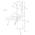
図1は、本発明の第1実施形態に係るチップの構造図である。チップ1は図1に示すように、例えば薄板状の基板2,3を互いに貼り合わせることにより形成されている。ここで、チップにおいて、生体との接触面を第1面F1と称し、その第1面F1と対向する面を第2面F2と称する。基板2,3の材料としては、例えば以下に示す有機化合物や、あるいはガラス、シリコン及び金属等の無機化合物のいずれもが挙げられる。有機化合物としては、PET(ポリエチレンテレフタレート)、PDMS(ポリジメチルシロキサン)、PMMA(ポリメチルメタクリレート)、PC(ポリカーボネイト)、PP(ポリプロピレン)、PS(ポリスチレン)、PVC(ポリ塩化ビニル)、ポリシロキサン、アリルエステル樹脂、シクロオレフィンポリマー、STゴム等が挙げられる。<First Embodiment>
(1) Structure FIG. 1 is a structural diagram of a chip according to the first embodiment of the present invention. As shown in FIG. 1, the
チップ1は、内部に形成された空間であって、被検体が導入される被検体導入部5を有している。チップ1は、第1面F1側に形成されており、被検体導入部5を形成する空間を外部空間と仕切っている薄肉部6を有する。本実施形態では、基板2の一部をその他の部分よりも薄く形成することにより、薄肉部6が形成されている。この薄肉部6は、チップ1を使用する際に生体を穿刺する針7が貫通可能な所定の厚さを有している。尚、針7は、チップ1の一部ではなく、チップ1を使用する際に別途設けられる。薄肉部6の所定の厚さは、薄肉部6の材質にもよるが、一般的には1μm〜1000μmであることができ、特に10μm〜50μmであると好ましい。被検体を採取する際は、チップ1の第1面F1及び薄肉部6が生体の皮膚に接触する。 The
また、チップ1の第2面F2には、被検体導入部5まで貫通する貫通孔5aが形成されている。生体から被検体を採取するのに用いる針7を、被検体導入部5に挿入するためである。本実施形態では、使用前には、チップ1の第1面F1側の薄肉部6には、貫通孔を設けていない。チップ1の使用時には、貫通孔5aを通じて被検体導入部5に外部から針7を挿入し、薄肉部6を介して生体を穿刺する。尚、チップ1の使用時には、針7を覆う針用カバー8を更に設ける。生体から得られる被検体は、薄肉部6に開けられた穴を通って被検体導入部5に導入される。 Further, a through
更に、チップ1の基板2,3内には採取した被検体の流路4を形成することができる。
このような構成によると、薄肉部6を介して生体へ針7を穿刺することで、チップ1の被検体導入部5に生体の被検体が導入される。
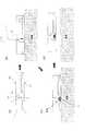
(2)使用方法
次に、本実施形態のチップ1を用いて被検体を採取する方法について説明する。以下より、説明を簡単にするため、被検体がヒトの血液である場合を例にとる。図2は、図1のチップ1の使用方法の説明図である。Furthermore, a
According to such a configuration, the living subject is introduced into the
(2) Usage Method Next, a method for collecting a subject using the
図2(a)は、血液を採取する前のチップ1である。
図2(b)は、チップ1をヒトの皮膚表面上に密着させた状態である。このとき、チップ1の基板2及び薄肉部6は、ヒトの皮膚表面に接触している。針用カバー8内の針7の先端と貫通孔5aとの位置が合うように、針7を内蔵した針用カバー8をチップ1上に載置する。この状態で、針用カバー8の上端を押すことにより針7を押下し、針7の先端を皮膚に穿刺する。尚、針7及び針用カバー8は、上から力がかからない状態では常に図2(b)の状態を保つようにチップ1に設置される。即ち、針7及び針用カバー8を押下してヒトの皮膚を穿刺した後は、針7及び針用カバー8は図2(b)の状態に戻る。また、針7の生体への穿刺には、針用カバー8内に内蔵されたスプリングの力を利用することも可能である。FIG. 2A shows the
FIG. 2B shows a state in which the
図2(c)は、ヒトの皮膚表面から出血した血液が、被検体導入部5に導入された状態を示している。皮膚に針7を穿刺することにより、薄肉部6には穴6aが形成される。この穴6aを介し、血液が被検体導入部5に導入される。被検体導入部5内の圧力よりも血圧の方が高い上に、チップ1の第1面F1が皮膚表面と密着しているからである。チップ1と皮膚との密着度が高いほど、血液は無駄なく被検体導入部5に導入されやすい。針7の穿刺後は、針7及び針用カバー8をチップ1から取り除く。 FIG. 2C shows a state in which blood that has bleed from the human skin surface has been introduced into the
図2(d)は、チップ1をヒトの皮膚表面から離した状態を示している。薄肉部6に開けられた穴6aは微小であるので、チップ1を皮膚表面から離しても、被検体導入部5に導入した血液は穴6aから漏洩せず内部に保持される。血液を採取後、採取した血液を保持したチップ1を遠心分離器等の分析器にかけることにより、所望の分析を行う。
(3)効果
生体表面にチップ1を密着させることにより、薄肉部6に開けられる穴から被検体導入部5に被検体を直接導入することができる。従って、解析のために採取すべき被検体の量を少量化できる。その結果、被検体の採取を手軽に行うことができる。FIG. 2D shows a state where the
(3) Effect By bringing the
(4)その他の構成1と効果
図1のチップ1において、薄肉部6の表面には粘着剤や接着剤を塗布してもよい。このようなチップ1は、粘着剤や接着剤が塗布されていないチップ1に比べて生体の皮膚にさらに密着する。従って、流出後の被検体は、薄肉部6の穴6aを経て被検体導入部5内にさらに無駄なく採取されやすくなる。尚、粘着剤や接着剤は、皮膚への負担が小さいアクリル系粘着剤が好ましいが、これに限定されることはなく、チップ1の薄膜と皮膚との密着性が高まるものであれば良い。(4)
(5)その他の構成2と効果
図1のチップ1において、薄肉部6の表面には、例えばキシロカイン等の局所麻酔剤を塗布してもよい。針7を生体の皮膚に突き刺して出血させる時、生体に痛みを感じさせることなく血液等の被検体を採取することができる。尚、局所麻酔剤の物質については特に限定はなく、皮膚に接触することにより麻酔効果を発揮するものであれば良い。(5)
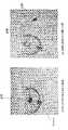
《実験例》
図3は、本発明の第1実施形態に係るチップ1の実験例である。
被験者の皮膚に接触する薄肉部6の表面にはアクリル系粘着剤を塗布した。このチップ1を被験者の皮膚に直接押し当てて血液を採取した。図3(a)は、被検体導入部5に血液を導入した状態を示す。このとき、チップ1が採取した血液の量は2.5μlであり、これは血液を分析するのに必要な量に相当する。また、血液を採取してチップを出血部位から離したところ、被験者の皮膚には残留血液は見られなかった。即ち、チップ1は、出血した量全ての血液を採取できたことになる。《Experimental example》
FIG. 3 is an experimental example of the
An acrylic pressure-sensitive adhesive was applied to the surface of the thin portion 6 that was in contact with the skin of the subject. Blood was collected by directly pressing the
その後、図3(a)のチップ1を遠心分離器にかけた。図3(b)は、遠心分離後の被検体の状態を示す。チップ1内の血液は、基板2,3内部に形成された流路4内で血漿と血球とに分離した。
<第2実施形態>
図4は、第2実施形態に係るチップ101の構造図である。このチップ101は、薄板状の基板102,103を互いに貼り合わせることにより形成されている。チップ101において、生体との接触面を第1面F1と称し、その第1面F1と対向する面を第2面F2と称する。このチップ101は、被検体導入部105と、薄肉部106とを有する。被検体導入部105は、基板102、103内部に形成された空間であって、被検体が導入される。薄肉部106は、チップ101の第1面F1側に形成されており、被検体導入部105を形成する空間を外部空間と仕切っている。また、薄肉部106は、フィルム109を含む。フィルム109は、他の部分よりも薄く形成された基板102上に形成されている。フィルム109は、チップ1の第1面F1を生体の皮膚により密着させるために設けられる。フィルム109は、被検体導入部105に対応する位置であって、かつチップ101を使用する際に外部からの針107が貫通する場所に対応するように配置されている。尚、針107が薄肉部106全体を貫通できるように、フィルム109は針107が貫通可能な所定の厚さを有するとよい。即ち、薄肉部106全体は、厚さ1μm〜1000μmであることが好ましく、特に10μm〜50μmが好ましい。また、フィルム109は、ポリエチレン等の熱可塑性材料やPDMS等のエラストマー、レーヨン等の繊維からなるのが好ましい。Thereafter, the
Second Embodiment
FIG. 4 is a structural diagram of the chip 101 according to the second embodiment. The chip 101 is formed by bonding thin plate-
フィルム109には、生体の皮膚とチップ101とがより密着するように粘着剤や接着剤を塗布ないしはしみこませるとよい。被検体がチップ101と生体との間に漏洩する被検体の量を抑え、被検体を無駄なくチップ101に導入しやすくなる。尚、粘着剤や接着剤は、皮膚への負担が小さいアクリル系粘着剤が好ましいが、これに限定されることはなく、チップ101の薄膜と皮膚との密着性が高まるものであれば良い。 The
また、フィルム109には、例えばキシロカイン等の局所麻酔剤を塗布ないしはしみこませると良い。針107が生体の皮膚を穿刺して被検体を流出させる場合、生体は痛みを感じることなく被検体を採取することができる。尚、局所麻酔剤の物質については特に限定はなく、皮膚に接触することにより麻酔効果を発揮するものであれば良い。
チップ101の第2面F2には、被検体導入部105まで貫通する貫通孔105aが形成されている。生体から被検体を採取するのに用いる針107を、被検体導入部105に挿入するためである。チップ101の使用時には、貫通孔105aを通じて被検体導入部105に外部から針107を挿入し、薄肉部106を介して生体を穿刺する。生体から得られる被検体は、薄肉部106に開けられた穴を通って被検体導入部105に導入される。In addition, a local anesthetic such as xylocaine is preferably applied or soaked on the
On the second surface F2 of the chip 101, a through-
生体から被検体を採取する場合、このチップ101のフィルム109が生体の皮膚に密着するようにチップ101を押し当てる。この場合、チップ101の第1面F1は、薄肉部106のみが形成されている場合よりも、生体の皮膚により密着する。従って、流出した被検体を漏れなく被検体導入部に導入することができる。
このような構成のチップ101は、薄肉部のみが形成されているチップに比して、生体の皮膚により密着する。従って、被検体を漏れなく被検体導入部105に導入することができる。When a subject is collected from a living body, the chip 101 is pressed so that the
The chip 101 having such a configuration is more closely attached to the skin of a living body than a chip in which only a thin portion is formed. Therefore, the subject can be introduced into the
《実験例》
本発明の第2実施形態に係るチップ101を用いて実験を行った。フィルム109にはポリエチレン製のフィルムを用い、被験者の皮膚に接触するフィルムの表面にはアクリル系粘着剤を塗布した。このチップ101を被験者の皮膚に直接押し当てて血液を2.5μl採取した。これは血液を分析するのに必要な量に相当する。また、血液を採取してチップを出血部位から離したところ、被験者の皮膚には残留血液は見られなかった。即ち、チップ101は、出血した量全ての血液を採取できたことになる。《Experimental example》
Experiments were performed using the chip 101 according to the second embodiment of the present invention. A polyethylene film was used as the
その後、チップ101を遠心分離器にかけた。すると、チップ101内の血液は、基板102,103内部に形成された流路104内で血漿と血球とに分離した。
<第3実施形態>
(1)構成
図5は、第3実施形態に係るチップ201の構造図である。チップ201は、基板202,203を互いに貼り合わせることにより形成されている。チップ201において生体との接触面を第1面F1と称し、第1面F1と対向する面を第2面F2と称する。このチップ201は、被検体導入部205と、フィルム209とを含む。被検体導入部205は、基板202、203内部に形成された空間であって、被検体が導入される。また、チップ201の第1面F1には、被検体導入部205を露出する開口部210が形成されている。開口部210は、生体と接触する第1面F1の少なくとも一部に形成されている。Thereafter, the chip 101 was centrifuged. Then, the blood in the chip 101 was separated into plasma and blood cells in the
<Third Embodiment>
(1) Configuration FIG. 5 is a structural diagram of a
フィルム209は、開口部210を覆うように形成されている。フィルム209は、チップ201の第1面F1を生体の皮膚に密着させるために設けられる。フィルム209の厚さは、外部からチップ201に挿入される針207がフィルム209を貫通可能な所定の厚さであればよい。具体的には、フィルム209の厚さは、1μm〜1000μmが好ましく、特に10μm〜50μmが好ましい。また、フィルム209は、ポリエチレン等の熱可塑性材料やPDMS等のエラストマー、レーヨン等の繊維からなるのが好ましい。 The
フィルム209には生体の皮膚とチップ201とがより密着するように粘着剤や接着剤を塗布ないしはしみこませても良い。被検体がチップ201と生体との間に漏洩する被検体の量を抑え、被検体を無駄なくチップ201に導入しやすくなる。尚、粘着剤は、皮膚への負担が小さいアクリル系粘着剤が好ましいが、これに限定されることはなく、チップ201のフィルム209と皮膚との密着性が高まれるものであれば良い。 The
また、フィルム209には、例えばキシロカイン等の局所麻酔剤を塗布ないしはしみこませても良い。針207を生体の皮膚に突き刺して被検体を流出させる場合、生体は痛みを感じることなく被検体を採取することができる。尚、局所麻酔剤の物質については特に限定はなく、皮膚に接触することにより麻酔効果を発揮するものであれば良い。
チップ1の第2面F2には、被検体導入部205まで貫通する貫通孔205aが形成されている。生体から被検体を採取するのに用いる針207を、被検体導入部205に挿入するためである。チップ201の使用時には、貫通孔205aを通じて被検体導入部205に外部から針207を挿入し、薄肉部206を介して生体を穿刺する。チップ201の使用時には、針207を覆う針用カバー208を更に設ける。生体から得られる被検体は、薄肉部206に開けられた穴を通って被検体導入部205に導入される。The
On the second surface F2 of the
また、チップ201の基板202,203内には、採取した被検体の流路204を形成することができる。
尚、上述した構成を有するチップ201を用いて被検体を採取し分析する方法については、第1実施形態の方法と同一であるため、説明を省略する。
(2)効果
このチップ201の構成によると、生体表面にチップ201を密着させることにより、フィルム209に開けられる穴及び開口部210から被検体導入部205に被検体を直接導入することができる。従って、解析のために採取すべき被検体の量を少量化できる。その結果、被検体の採取を手軽に行うことができる。In addition, a
Note that a method for collecting and analyzing a subject using the
(2) Effect According to the configuration of the
《実験例》
本発明の第3実施形態に係るチップ201を用いて実験を行った。フィルム209にはポリエチレン製のフィルムを用い、被験者の皮膚に接触するフィルムの表面にはアクリル系粘着剤を塗布した。このチップ201を被験者の皮膚に直接押し当てて血液を2.5μl採取した。これは血液を分析するのに必要な量に相当する。また、血液を採取してチップを出血部位から離したところ、被験者の皮膚には残留血液は見られなかった。即ち、チップ201は、出血した量全ての血液を採取できたことになる。《Experimental example》
Experiments were performed using the
その後、チップ201を遠心分離器にかけた。すると、チップ201内の血液は、基板202,203内部に形成された流路204内で血漿と血球とに分離した。
<第4実施形態>
(1)構成
図6は、第4実施形態に係るチップ301の構造図である。チップ301は、薄板状の基板302,303を互いに貼り合わせることにより形成されている。チップ301において、生体との接触面を第1面F1と称し、第1面F1と対向する面を第2面F2と称する。このチップ301は、被検体導入部305と、薄肉部306とを有する。被検体導入部305は、基板302、303内部に形成された空間であって、被検体が導入される。薄肉部306は、チップ301の第1面F1側に形成されており、被検体導入部305を形成する空間を外部空間と仕切っている。具体的には、薄肉部306は、他の部分よりも薄く形成された基板302の一部によって形成されている。Thereafter, the
<Fourth embodiment>
(1) Configuration FIG. 6 is a structural diagram of a
薄肉部306には生体の皮膚とチップ301とがより密着するように粘着剤や接着剤を塗布ないしはしみこませても良い。被検体がチップ301と生体との間に漏洩する被検体の量を抑え、被検体を無駄なくチップ301に導入しやすくなる。尚、接着剤は、皮膚への負担が小さいアクリル系粘着剤が好ましいが、これに限定されることはなく、チップ301の薄肉部306と皮膚との密着性が高まれるものであれば良い。 An adhesive or an adhesive may be applied or soaked into the thin-
また、薄肉部306には、例えばキシロカイン等の局所麻酔剤を塗布ないしはしみこませても良い。針307を生体の皮膚に突き刺して流出させる場合、生体は痛みを感じることなく被検体を採取することができる。尚、局所麻酔剤の物質については特に限定はなく、皮膚に接触することにより麻酔効果を発揮するものであれば良い。
薄肉部306には、薄肉部306を貫通する貫通孔311が形成されている。貫通孔311は外部からチップ301に挿入される針307の位置と対応するように形成されている。貫通孔311の直径は、被検体導入部305に導入された被検体が漏洩しない大きさであればよい。貫通孔311の直径は、被検体の粘度にもよるが、一般的には50μm〜3mmの範囲が好ましく、特に100〜500μmであると好ましい。Further, a local anesthetic such as xylocaine may be applied to or impregnated into the
The
また、チップ301の第2面F2には、被検体導入部305まで貫通する貫通孔305aが形成されている。生体から被検体を採取するのに用いる針307を、被検体導入部305に挿入するためである。チップ301の使用時には、貫通孔305aを通じて被検体導入部305に外部から針307を挿入し、薄肉部306を介して生体を穿刺する。尚、チップ301の使用時には、針307を覆う針用カバー308を更に設ける。生体から得られる被検体は、貫通孔311を通って被検体導入部305に導入される。 In addition, a through
更に、チップ301の基板302,303内には、採取した被検体の流路304を形成することができる。
尚、上述した構成を有するチップ301を用いて被検体を採取する方法については、第1実施形態の方法と同一であるため、説明を省略する。
(2)効果
この構成を有するチップ301によると、被検体はチップ301の薄肉部306及び貫通孔311を経て被検体導入部305内に直接流入する。従って、注射器等を用いて皮膚から被検体を採取し、採取した被検体をチップに入れる手間を省くことができ、手軽に被検体を採取することができる。また、被検体採取後の皮膚には被検体が残らない。そのため、被検体を採取した後でも皮膚を清潔に保つことができる。Furthermore, a
Note that a method of collecting a subject using the
(2) Effect According to the
《実験例》
本発明の第4実施形態に係るチップ301を用いて実験を行った。被験者の皮膚に接触する薄肉部306の表面にはアクリル系粘着剤を塗布した。このチップ301を被験者の皮膚に直接押し当てて血液を2.5μl採取した。これは血液を分析するのに必要な量に相当する。また、血液を採取してチップを出血部位から離したところ、被験者の皮膚には残留血液は見られなかった。即ち、チップ301は、出血した量全ての血液を採取できたことになる。《Experimental example》
Experiments were performed using the
その後、チップ301を遠心分離器にかけた。すると、チップ301内の血液は、基板302,303内部に形成された流路304内で血漿と血球とに分離した。
<第5実施形態>
図7は、本発明の第5実施形態に係るチップ401の構造図である。チップ401は、薄板状の基板402,403を互いに貼り合わせることにより形成されている。チップ401において、生体との接触面を第1面F1と称し、第1面F1と対向する面を第2面F2と称する。このチップ401は、被検体導入部405と、薄肉部406と、針407とを含む。被検体導入部405は、基板402,403内部に形成された空間であって、被検体が導入される。薄肉部406は、チップ401の第1面F1側に形成されており、被検体導入部405を形成する空間を外部空間と仕切っている。また、薄肉部406は、フィルム409を含む。また、薄肉部406には、被検体導入部405を露出する貫通孔411が形成されている。フィルム409は、薄肉部406上の少なくとも一部に設けられている。具体的には、フィルム409は、他の部分よりも薄く形成された基板402上に形成されている。フィルム409は、チップ401の第1面F1を生体の皮膚により密着させるために設けられる。Thereafter, the
<Fifth Embodiment>
FIG. 7 is a structural diagram of a
フィルム409には、生体の皮膚とチップ401とがより密着するように粘着剤や接着剤を塗布ないしはしみこませるとよい。被検体がチップ401と生体との間に漏洩する被検体の量を抑え、被検体を無駄なくチップ401に導入しやすくなる。尚、接着剤は、皮膚への負担が小さいアクリル系粘着剤が好ましいが、これに限定されることはなく、チップ401の薄膜と皮膚との密着性が高まるものであれば良い。 The
また、フィルム409には、例えばキシロカイン等の局所麻酔剤を塗布ないしはしみこませると良い。針407が生体の皮膚を穿刺して被検体を流出させる場合、生体は痛みを感じることなく被検体を採取することができる。尚、局所麻酔剤の物質については特に限定はなく、皮膚に接触することにより麻酔効果を発揮するものであれば良い。
尚、薄肉部406には、必ずしもフィルム409を設ける必要はない。The
Note that the
本実施形態に係るチップ401には、針407が内蔵されている。針407は、被検体導入部405の内壁に、かつ薄肉部406の貫通孔411と対向する位置に設けられている。また、チップ401の基板402,403内には、採取した被検体の流路404を形成することができる。
チップ401を用いて被検体を採取する場合は、チップ401のフィルム409が生体の皮膚に直接接触するようにチップ401を載置する。そして、穿刺針407上部からチップ401を押圧する。すると、内蔵された針407は貫通孔411を経て生体の皮膚を穿刺する。これにより、被検体が被検体導入部405に導入される。The
When the subject is collected using the
この構成を有するチップ401によると、生体から被検体を採取する際に、針を別途準備しなくて済む。従って、被験者は、このチップ401を皮膚に載置させて押下するだけで、被検体を採取することができる。
尚、前記第1〜4実施形態に記載のチップにおいても、外部から被検体導入部に貫通する貫通孔に代えて、本実施形態に記載の針の構造を適用することができる。According to the
In the chips described in the first to fourth embodiments, the structure of the needle described in the present embodiment can be applied instead of the through hole penetrating from the outside into the subject introduction part.
《実験例》
本発明の第5実施形態に係るチップ401を用いて実験を行った。フィルム409にはポリエチレン製のフィルムを用い、被験者の皮膚に接触するフィルムの表面にはアクリル系粘着剤を塗布した。このチップ401を被験者の皮膚に直接押し当てて血液を2.5μl採取した。これは血液を分析するのに必要な量に相当する。また、血液を採取してチップを出血部位から離したところ、被験者の皮膚には残留血液は見られなかった。即ち、チップ401は、出血した量全ての血液を採取できたことになる。《Experimental example》
Experiments were performed using the
その後、チップ401を遠心分離器にかけた。すると、チップ401内の血液は、基板402,403内部に形成された流路404内で血漿と血球とに分離した。 Thereafter, the
本発明を用いれば、被検体の採取が手軽にできるチップ、即ちバイオチップを得ることができる。 By using the present invention, it is possible to obtain a chip that can easily collect a specimen, that is, a biochip.
1 チップ
2、3 基板
4 流路
5 被検体導入部
5a 貫通孔
6 薄肉部
7 針
8 針用カバー
109 フィルム
210 開口部
311 貫通孔DESCRIPTION OF
Claims (8)
Translated fromJapanese薄板状の主体と、
前記主体内部に形成され、前記被検体が導入される被検体導入部と、
前記被検体導入部を形成する空間を外部空間と仕切っている薄肉部と、
を備えるチップ。A chip for collecting a subject from a living body,
A thin plate-shaped main body,
A subject introduction part formed inside the main body and into which the subject is introduced;
A thin-walled portion that partitions the space forming the subject introduction portion from the external space;
Chip with.
前記フィルムは、前記開口部を覆うように形成されている、請求項2に記載のチップ。An opening for exposing the subject introduction part is formed in the main body,
The chip according to claim 2, wherein the film is formed so as to cover the opening.
Priority Applications (3)
| Application Number | Priority Date | Filing Date | Title |
|---|---|---|---|
| JP2005237201AJP2007050100A (en) | 2005-08-18 | 2005-08-18 | Chip for sampling specimen |
| US12/063,561US20090105614A1 (en) | 2005-08-18 | 2006-08-15 | Analyte collection chip |
| PCT/JP2006/316030WO2007020918A1 (en) | 2005-08-18 | 2006-08-15 | Analyte collection chip |
Applications Claiming Priority (1)
| Application Number | Priority Date | Filing Date | Title |
|---|---|---|---|
| JP2005237201AJP2007050100A (en) | 2005-08-18 | 2005-08-18 | Chip for sampling specimen |
Publications (1)
| Publication Number | Publication Date |
|---|---|
| JP2007050100Atrue JP2007050100A (en) | 2007-03-01 |
Family
ID=37757578
Family Applications (1)
| Application Number | Title | Priority Date | Filing Date |
|---|---|---|---|
| JP2005237201APendingJP2007050100A (en) | 2005-08-18 | 2005-08-18 | Chip for sampling specimen |
Country Status (3)
| Country | Link |
|---|---|
| US (1) | US20090105614A1 (en) |
| JP (1) | JP2007050100A (en) |
| WO (1) | WO2007020918A1 (en) |
Cited By (3)
| Publication number | Priority date | Publication date | Assignee | Title |
|---|---|---|---|---|
| JP2016518926A (en)* | 2013-04-15 | 2016-06-30 | ベクトン・ディキンソン・アンド・カンパニーBecton, Dickinson And Company | Blood collection and transportation device |
| JP2016518925A (en)* | 2013-04-15 | 2016-06-30 | ベクトン・ディキンソン・アンド・カンパニーBecton, Dickinson And Company | Biological fluid sampling transfer device and biological fluid separation and inspection system |
| JP2019034198A (en)* | 2013-04-15 | 2019-03-07 | ベクトン・ディキンソン・アンド・カンパニーBecton, Dickinson And Company | Living body fluid separation device |
Families Citing this family (18)
| Publication number | Priority date | Publication date | Assignee | Title |
|---|---|---|---|---|
| JP2011522616A (en)* | 2008-06-04 | 2011-08-04 | セブンス センス バイオシステムズ,インコーポレーテッド | Compositions and methods for single-step diagnosis |
| US20100256524A1 (en) | 2009-03-02 | 2010-10-07 | Seventh Sense Biosystems, Inc. | Techniques and devices associated with blood sampling |
| WO2011094573A1 (en) | 2010-01-28 | 2011-08-04 | Seventh Sense Biosystems, Inc. | Monitoring or feedback systems and methods |
| WO2011163347A2 (en) | 2010-06-23 | 2011-12-29 | Seventh Sense Biosystems, Inc. | Sampling devices and methods involving relatively little pain |
| US20120016308A1 (en) | 2010-07-16 | 2012-01-19 | Seventh Sense Biosystems, Inc. | Low-pressure packaging for fluid devices |
| US20130158482A1 (en) | 2010-07-26 | 2013-06-20 | Seventh Sense Biosystems, Inc. | Rapid delivery and/or receiving of fluids |
| WO2012021801A2 (en) | 2010-08-13 | 2012-02-16 | Seventh Sense Biosystems, Inc. | Systems and techniques for monitoring subjects |
| WO2012064802A1 (en) | 2010-11-09 | 2012-05-18 | Seventh Sense Biosystems, Inc. | Systems and interfaces for blood sampling |
| US20130158468A1 (en) | 2011-12-19 | 2013-06-20 | Seventh Sense Biosystems, Inc. | Delivering and/or receiving material with respect to a subject surface |
| WO2012149155A1 (en)* | 2011-04-29 | 2012-11-01 | Seventh Sense Biosystems, Inc. | Systems and methods for collecting fluid from a subject |
| CN103874461B (en)* | 2011-04-29 | 2017-05-10 | 第七感生物系统有限公司 | Devices for collecting and/or manipulating blood spots or other bodily fluids |
| KR102013466B1 (en) | 2011-04-29 | 2019-08-22 | 세븐쓰 센스 바이오시스템즈, 인크. | Delivering and/or receiving fluids |
| JP6295044B2 (en)* | 2013-09-11 | 2018-03-14 | 学校法人 関西大学 | Puncture device set |
| US10765361B2 (en)* | 2015-03-02 | 2020-09-08 | Verily Life Sciences Llc | Automated sequential injection and blood draw |
| US12053284B2 (en) | 2021-11-08 | 2024-08-06 | Satio, Inc. | Dermal patch for collecting a physiological sample |
| US12178979B2 (en) | 2021-10-13 | 2024-12-31 | Satio, Inc. | Dermal patch for delivering a pharmaceutical |
| US12214346B2 (en) | 2021-10-13 | 2025-02-04 | Satio, Inc. | Dermal patch with a diagnostic test strip |
| EP4622547A1 (en)* | 2022-11-21 | 2025-10-01 | Satio, Inc. | Dermal patch for collecting a physiological sample with removable vial |
Citations (8)
| Publication number | Priority date | Publication date | Assignee | Title |
|---|---|---|---|---|
| US5636640A (en)* | 1995-02-06 | 1997-06-10 | Volunteers For Medical Engineering | Liquid sampling and test apparatus |
| JPH09168530A (en)* | 1995-10-17 | 1997-06-30 | Dainippon Printing Co Ltd | Body fluid collecting device and body fluid analyzer using the same |
| JPH10501992A (en)* | 1992-10-28 | 1998-02-24 | ベニセクト・インコーポレイテッド | Laser drilling equipment |
| US6132449A (en)* | 1999-03-08 | 2000-10-17 | Agilent Technologies, Inc. | Extraction and transportation of blood for analysis |
| WO2003025559A1 (en)* | 2001-09-11 | 2003-03-27 | Arkray, Inc. | Measuring instrument, installation body, and density measurer |
| JP2004065775A (en)* | 2002-08-08 | 2004-03-04 | Sanwa Kagaku Kenkyusho Co Ltd | Device equipped with needle-like structure element |
| JP2004522500A (en)* | 2001-01-22 | 2004-07-29 | エフ ホフマン−ラ ロッシュ アクチェン ゲゼルシャフト | Lancet device with capillary action |
| JP2005074125A (en)* | 2003-09-03 | 2005-03-24 | Enomoto Co Ltd | Blood sampling bandage |
Family Cites Families (6)
| Publication number | Priority date | Publication date | Assignee | Title |
|---|---|---|---|---|
| US4883763A (en)* | 1984-05-03 | 1989-11-28 | Abbott Laboratories | Sample processor card for centrifuge |
| US5014718A (en)* | 1988-01-22 | 1991-05-14 | Safety Diagnostics, Inc. | Blood collection and testing method |
| DK120991D0 (en)* | 1991-06-21 | 1991-06-21 | Novo Nordisk As | BLOOD SAMPLES |
| US20060015058A1 (en)* | 1998-01-08 | 2006-01-19 | Kellogg Scott C | Agents and methods for enhancement of transdermal transport |
| EP1399067A1 (en)* | 2001-06-08 | 2004-03-24 | Roche Diagnostics GmbH | Sampling devices and methods utilizing a horizontal capillary test strip |
| US7264627B2 (en)* | 2001-08-29 | 2007-09-04 | Roche Diagnostics Operations, Inc. | Wicking methods and structures for use in sampling bodily fluids |
- 2005
- 2005-08-18JPJP2005237201Apatent/JP2007050100A/enactivePending
- 2006
- 2006-08-15USUS12/063,561patent/US20090105614A1/ennot_activeAbandoned
- 2006-08-15WOPCT/JP2006/316030patent/WO2007020918A1/enactiveApplication Filing
Patent Citations (8)
| Publication number | Priority date | Publication date | Assignee | Title |
|---|---|---|---|---|
| JPH10501992A (en)* | 1992-10-28 | 1998-02-24 | ベニセクト・インコーポレイテッド | Laser drilling equipment |
| US5636640A (en)* | 1995-02-06 | 1997-06-10 | Volunteers For Medical Engineering | Liquid sampling and test apparatus |
| JPH09168530A (en)* | 1995-10-17 | 1997-06-30 | Dainippon Printing Co Ltd | Body fluid collecting device and body fluid analyzer using the same |
| US6132449A (en)* | 1999-03-08 | 2000-10-17 | Agilent Technologies, Inc. | Extraction and transportation of blood for analysis |
| JP2004522500A (en)* | 2001-01-22 | 2004-07-29 | エフ ホフマン−ラ ロッシュ アクチェン ゲゼルシャフト | Lancet device with capillary action |
| WO2003025559A1 (en)* | 2001-09-11 | 2003-03-27 | Arkray, Inc. | Measuring instrument, installation body, and density measurer |
| JP2004065775A (en)* | 2002-08-08 | 2004-03-04 | Sanwa Kagaku Kenkyusho Co Ltd | Device equipped with needle-like structure element |
| JP2005074125A (en)* | 2003-09-03 | 2005-03-24 | Enomoto Co Ltd | Blood sampling bandage |
Cited By (6)
| Publication number | Priority date | Publication date | Assignee | Title |
|---|---|---|---|---|
| JP2016518926A (en)* | 2013-04-15 | 2016-06-30 | ベクトン・ディキンソン・アンド・カンパニーBecton, Dickinson And Company | Blood collection and transportation device |
| JP2016518925A (en)* | 2013-04-15 | 2016-06-30 | ベクトン・ディキンソン・アンド・カンパニーBecton, Dickinson And Company | Biological fluid sampling transfer device and biological fluid separation and inspection system |
| JP2019034198A (en)* | 2013-04-15 | 2019-03-07 | ベクトン・ディキンソン・アンド・カンパニーBecton, Dickinson And Company | Living body fluid separation device |
| US10827965B2 (en) | 2013-04-15 | 2020-11-10 | Becton, Dickinson And Company | Biological fluid collection device and biological fluid separation and testing system |
| US11974846B2 (en) | 2013-04-15 | 2024-05-07 | Becton, Dickinson And Company | Biological fluid transfer device and biological fluid sampling system |
| US12082931B2 (en) | 2013-04-15 | 2024-09-10 | Becton, Dickinson And Company | Blood sampling transfer device |
Also Published As
| Publication number | Publication date |
|---|---|
| WO2007020918A1 (en) | 2007-02-22 |
| US20090105614A1 (en) | 2009-04-23 |
Similar Documents
| Publication | Publication Date | Title |
|---|---|---|
| US20090105614A1 (en) | Analyte collection chip | |
| US12082931B2 (en) | Blood sampling transfer device | |
| US10136849B2 (en) | Biological fluid collection device and biological fluid separation and testing system | |
| JP6055773B2 (en) | System and interface for blood sampling | |
| US9808192B2 (en) | Biological fluid sampling transfer device and biological fluid separation and testing system | |
| CA2909183C (en) | Blood sampling transfer device | |
| JP5002266B2 (en) | Body fluid collection device | |
| CA2909227C (en) | Biological fluid transfer device and biological fluid sampling system | |
| JP4953139B2 (en) | Biosensor chip |
Legal Events
| Date | Code | Title | Description |
|---|---|---|---|
| A621 | Written request for application examination | Free format text:JAPANESE INTERMEDIATE CODE: A621 Effective date:20080318 | |
| A131 | Notification of reasons for refusal | Free format text:JAPANESE INTERMEDIATE CODE: A131 Effective date:20100629 | |
| A02 | Decision of refusal | Free format text:JAPANESE INTERMEDIATE CODE: A02 Effective date:20101026 |