JP2007048135A - Method for acquiring coordinate position on projection plane using dmd - Google Patents
Method for acquiring coordinate position on projection plane using dmdDownload PDFInfo
- Publication number
- JP2007048135A JP2007048135AJP2005233325AJP2005233325AJP2007048135AJP 2007048135 AJP2007048135 AJP 2007048135AJP 2005233325 AJP2005233325 AJP 2005233325AJP 2005233325 AJP2005233325 AJP 2005233325AJP 2007048135 AJP2007048135 AJP 2007048135A
- Authority
- JP
- Japan
- Prior art keywords
- projection
- projector
- image data
- position information
- light
- Prior art date
- Legal status (The legal status is an assumption and is not a legal conclusion. Google has not performed a legal analysis and makes no representation as to the accuracy of the status listed.)
- Pending
Links
- 238000000034methodMethods0.000titleclaimsdescription16
- 230000005540biological transmissionEffects0.000claimsdescription20
- 238000004364calculation methodMethods0.000claimsdescription8
- 238000001514detection methodMethods0.000claimsdescription7
- 238000004891communicationMethods0.000claimsdescription5
- 230000002194synthesizing effectEffects0.000claimsdescription5
- 230000001678irradiating effectEffects0.000claimsdescription4
- 230000005855radiationEffects0.000abstract4
- 238000010586diagramMethods0.000description12
- 230000006870functionEffects0.000description6
- 238000012545processingMethods0.000description6
- 230000003287optical effectEffects0.000description5
- 239000003086colorantSubstances0.000description2
- 230000007423decreaseEffects0.000description2
- 230000004044responseEffects0.000description2
- XUIMIQQOPSSXEZ-UHFFFAOYSA-NSiliconChemical compound[Si]XUIMIQQOPSSXEZ-UHFFFAOYSA-N0.000description1
- 230000015572biosynthetic processEffects0.000description1
- 230000004907fluxEffects0.000description1
- 238000012905input functionMethods0.000description1
- 239000003550markerSubstances0.000description1
- 238000005259measurementMethods0.000description1
- 238000012986modificationMethods0.000description1
- 230000004048modificationEffects0.000description1
- 238000001454recorded imageMethods0.000description1
- 229910052710siliconInorganic materials0.000description1
- 239000010703siliconSubstances0.000description1
- 239000000758substrateSubstances0.000description1
- 238000003786synthesis reactionMethods0.000description1
Images


Landscapes
- Drawing Aids And Blackboards (AREA)
- Projection Apparatus (AREA)
- Position Input By Displaying (AREA)
- Control Of Indicators Other Than Cathode Ray Tubes (AREA)
Abstract
Description
Translated fromJapanese本発明は、テレビやDVDなどの映像を投影することができる前面投射型または背面投射型のプロジェクタに関し、特に、プロジェクタの投影面に位置情報を投影することができるプロジェクタおよび投影面の座標位置を取得することができるプロジェクタシステムに関する。 The present invention relates to a front projection type projector or a rear projection type projector capable of projecting an image such as a television or a DVD, and more particularly to a projector capable of projecting position information on a projection plane of the projector and a coordinate position of the projection plane. The present invention relates to a projector system that can be obtained.
プロジェクタによる投影画像に、筆記情報を合成して表示する電子黒板機能とプロジェクタ機能をもつ投影表示システムが知られている。これは、電子黒板の所定の位置に超音波を発生させる装置を配置して、ペンの位置を三角測量の原理により検出し、検出された位置情報を基にして、筆記情報を作成し、投影画像に合成させるものである。 2. Description of the Related Art A projection display system having an electronic blackboard function that combines and displays handwritten information on a projection image by a projector and a projector function is known. This is a device that generates ultrasonic waves at a predetermined position on the electronic blackboard, detects the position of the pen based on the principle of triangulation, creates writing information based on the detected position information, and projects it. It is synthesized with the image.
特許文献1は、プロジェクタを使用した電子黒板システムに関するもので、図13(A)に示すように、ホワイトボード1の信号処理器2に、赤外光受光部21、超音波受信部22、超音波受信部23が設けられている。電子ペン3からは、同時に赤外光パルス4と超音波パルス5が出力される。雷の光が見えてから音が聞こえるまでの時間で雷までの距離が判る原理を利用し、信号処理器2は赤外光受光部20に赤外光パルス4が入力してから、超音波受信部21、22に超音波が入力するまでの時間を測ることで、電子ペン3から超音波受信部21、22までの距離を知ることができる。超音波受光部21,22は信号処理器2に固定されていることから、超音波受信部21、22からみた電子ペン3の位置は三角測量の原理から求めることができる。図13(B)に示すように、プロジェクタでホワイトボードに映像を投射し、投射映像6のどの位置に電子ペン3があるかを算出し、その結果、パソコンに電子ペンの座標を出力したり、またマウスカーソルを動かしたり、画面上のアイコンを指定することを可能にしている。
特許文献2は、電子黒板システムに関するもので、表示データを投影するスクリーンには、マーカ等のインクにより手書きで加筆されることができ、その加筆内容が電子黒板の読取部12で読み取られ、読取られた手書きデータと現在投影中の表示データがパソコンにて合成され、合成されたデータがプリンタから出力されるものである。 Patent Document 2 relates to an electronic blackboard system. A screen on which display data is projected can be handwritten with ink such as a marker, and the added content is read and read by the reading unit 12 of the electronic blackboard. The generated handwritten data and the currently projected display data are combined by a personal computer, and the combined data is output from the printer.
特許文献3は、マルチメディアプロジェクタに関し、投影像を外部カメラで撮像し、撮像された映像信号がケーブルを介してマルチメディアプロジェクタのビデオ信号入力端子に接続され、マルチメディアプロジェクタ内の画像メモリに記録され、これにより、記録映像を投影することと紙へ印字することを可能にしている。 Patent Document 3 relates to a multimedia projector, and captures a projected image with an external camera, and the captured video signal is connected to a video signal input terminal of the multimedia projector via a cable and recorded in an image memory in the multimedia projector. Thus, it is possible to project a recorded image and print it on paper.
しかしながら、特許文献1に示すような電子黒板システムでは、超音波発生装置のようなものをプロジェクタの投影画面に設けなければならず、利用できる場所や範囲が限定されてしまう。他の特許文献においても、手書き文字を撮像する外部カメラ等を必要とし、装置が大型化し、コストも高くなるという課題がある。 However, in the electronic blackboard system as shown in
本発明は、上記従来の課題を解決するものであり、プロジェクタの投影面に位置情報を投影し、かつ、投影面の位置情報の検出を容易に行うことが可能なプロジェクタおよびプロジェクタシステムを提供することを目的とする。
さらに本発明は、投影面の位置情報を取得して、投影面上に入力ペン等の入力情報を併せて投影表示することができるプロジェクタおよびプロジェクタシステムを提供することを目的とする。The present invention solves the above-described conventional problems, and provides a projector and a projector system capable of projecting position information onto the projection surface of the projector and easily detecting the position information of the projection surface. For the purpose.
It is another object of the present invention to provide a projector and a projector system that can acquire position information of a projection plane and project and display input information such as an input pen on the projection plane.
本発明に係る、プロジェクタにより投影される投影面に位置情報を投影する投影方法は、可視光の投影動作中に、投影面の位置に応じて明るさが変化する投影パターンを投影するものである。好ましくは、投影パターンは、投影面の縦方向に明るさが階調的に変化する第1の投影パターンと、投影面の横方向に明るさが階調的に変化する第2の投影パターンとを含み、投影パターンは、可視光以外の波長、例えば、赤外光を用いてディジタルマイクロミラーデバイス(以下、DMDという)により投影される。 According to the present invention, a projection method for projecting position information onto a projection plane projected by a projector projects a projection pattern whose brightness changes according to the position of the projection plane during a visible light projection operation. . Preferably, the projection pattern includes a first projection pattern whose brightness changes in a gradation in the vertical direction of the projection plane, and a second projection pattern whose brightness changes in a gradation in the horizontal direction of the projection plane. The projection pattern is projected by a digital micromirror device (hereinafter referred to as DMD) using a wavelength other than visible light, for example, infrared light.
位置情報の投影方法はさらに、投影パターンに基づき投影された投影面の所定領域の明るさを検出するステップと、検出された信号に基づき投影面の前記所定領域の座標位置を算出するステップとを有することができる。検出するステップは、DMDによる照射時間を検出する。 The method of projecting position information further includes the steps of detecting the brightness of a predetermined area of the projection surface projected based on the projection pattern, and calculating the coordinate position of the predetermined area of the projection surface based on the detected signal. Can have. In the detecting step, an irradiation time by DMD is detected.
位置情報の投影方法はさらに、算出された座標位置に基づき画像データを作成するステップと、作成された画像データと投影用の画像データを合成するステップと、合成された画像データを投影面に投影するステップとを有することができる。この検出するステップは、投影面上においてポインティング装置を移動することにより行われ、合成された画像データは、ポインティング装置の移動軌跡を含む。 The method of projecting position information further includes a step of creating image data based on the calculated coordinate position, a step of synthesizing the created image data and image data for projection, and projecting the synthesized image data onto a projection plane. Can be included. This detecting step is performed by moving the pointing device on the projection plane, and the synthesized image data includes the movement locus of the pointing device.
本発明に係る、投影面に画像データを投影するプロジェクタは、光源と、光源からの光をDMDに照射する照射手段と、照射された光を変調するDMDと、DMDにより変調された光を投影面に投影する投影手段と、投影面の明るさが2次元的に変化する投影パターンを記憶する記憶手段と、投影パターンに基づきDMDを駆動する制御手段とを有する。 A projector for projecting image data on a projection surface according to the present invention projects a light source, an irradiation means for irradiating light from the light source to the DMD, a DMD for modulating the irradiated light, and light modulated by the DMD. Projection means for projecting onto a surface, storage means for storing a projection pattern in which the brightness of the projection surface changes two-dimensionally, and control means for driving the DMD based on the projection pattern.
好ましくは、投影パターンは、投影面の縦方向の明るさが階調的に変化する第1の投影パターンと、投影面の横方向の明るさが階調的に変化する第2の投影パターンを含み、照射手段は、光源から赤外光を選択し、選択された赤外光光をDMDに照射したとき、制御手段が投影パターンによりDMDを駆動する。 Preferably, the projection pattern includes a first projection pattern in which the vertical brightness of the projection plane changes in gradation and a second projection pattern in which the horizontal brightness of the projection plane changes in gradation. The irradiating means selects infrared light from the light source, and when the selected infrared light is irradiated to the DMD, the control means drives the DMD with the projection pattern.
さらに本発明に係るプロジェクタシステムは、上記構成のプロジェクタと、プロジェクタとデータ通信が可能なポインティング装置とを有し、ポインティング装置は、投影パターンに基づき投影された投影面の所定領域の明るさを検出する検出手段と、検出された信号を送信する送信手段とを含み、プロジェクタは、送信された信号に基づき所定領域に対応する画像データを作成する手段と、作成された画像データと投影用の画像データを合成する手段とを有し、前記制御手段は、合成された画像データに基づきDMDを駆動するものである。好ましくは、プロジェクタは、電子黒板の描画面に画像データを投影する。 Furthermore, a projector system according to the present invention includes the projector having the above-described configuration and a pointing device capable of data communication with the projector, and the pointing device detects the brightness of a predetermined area of the projection surface projected based on the projection pattern. The projector includes: a detecting unit configured to transmit the detected signal; and a projector configured to generate image data corresponding to a predetermined area based on the transmitted signal, the generated image data, and the projection image. Means for synthesizing data, and the control means drives the DMD based on the synthesized image data. Preferably, the projector projects image data onto a drawing surface of the electronic blackboard.
本発明によれば、投影面において、2次元的に明るさが変化する投影パターンを投影面に投影することで、投影面の位置情報を表示し、かつ、その位置情報から所定領域の座標位置を取得することができる。これにより、従来のように特殊な装置を用いることなく、簡単な検出用センサーを用いて座標位置を算出することができる。また、取得した座標位置を利用して、投影面にペン等の入力装置により筆記された情報を、画像データとして投影面に投影することができる。 According to the present invention, by projecting a projection pattern whose brightness changes two-dimensionally on the projection plane onto the projection plane, the position information of the projection plane is displayed, and the coordinate position of the predetermined area is determined from the position information. Can be obtained. Thus, the coordinate position can be calculated using a simple detection sensor without using a special device as in the prior art. In addition, by using the acquired coordinate position, information written by an input device such as a pen on the projection surface can be projected on the projection surface as image data.
以下、本発明に係るプロジェクタシステムの好ましくは構成を図面を参照して詳細に説明する。 Hereinafter, a preferred configuration of the projector system according to the present invention will be described in detail with reference to the drawings.
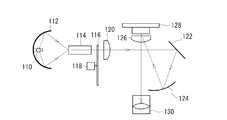
図1は、本発明の実施例に係るプロジェクタシステムの構成を示す図である。プロジェクタシステム10は、背面投射型のプロジェクタ100と、プロジェクタ100による投影面上で操作されるポインティング装置200とを有する。ポインティング装置200は、有線または無線によりデータをプロジェクタ100に送信可能であり、また、ポインティング装置200は、後述するように、投影面に映し出された文字、図形、映像等の画像に対して、文字や図形等を入力するための入力装置として機能する。 FIG. 1 is a diagram showing a configuration of a projector system according to an embodiment of the present invention. The projector system 10 includes a rear
図2は、プロジェクタ100の一般的な構成を示す図である。同図は、DMD(Digital Micro-mirror Device)を用いたDLP方式のプロジェクタを示している。ランプ110から発せられた光は、集光ミラーである楕円ミラー112で反射され、光学部品であるライトトンネルまたは光インテグレータ114に入射される。ライトトンネル114において均一な光線束とされた光は、カラーホイール116に入射される。 FIG. 2 is a diagram illustrating a general configuration of the
カラーホイール116は、円周上にR(赤色)、G(緑色)、B(青色)のカラーフィルターと赤外光の透過フィルターを配列しており、これらがモータ118によって回転される。カラーホイール116に入射された光は、R、G、Bの可視光と、可視光以外の赤外光に分離され、R、G、B光および赤外光が、順次、コンデンサレンズ120、折り返し用の平面ミラー122、第2の折り返し用の球面ミラー124、第2のコンデンサレンズ126を介してDMD128を照明する。DMD128の反射光は、投影レンズ130に入射され、そこで拡大されスクリーン状に映像が投影される。 The
図3は、カラーホイールの構成を示す図である。カラーホール116は、R、G、Bのカラーフィルター140、142、144と、波長の異なる赤外光を透過するための赤外光透過フィルター146、148を有している。ランプ110により発光される光は、可視光の波長と赤外光の波長を含んでおり、この光が、回転するカラーホイール116に対して略垂直に入射され、カラーホイール116からは、赤(R)、緑(G)、青(B)、および2つの赤外光が順次出射される。こうして、ランプ110から発せられた光は、カラーホイール116により可視光と2つの赤外光に分離される。 FIG. 3 is a diagram showing the configuration of the color wheel. The
図4は、DMDの平面図である。DMD128は、シリコン基板上に複数のミラー150を2次元アレイ状に配列している。ミラー150は、M行×N列に配置され、例えば、XGA、SVGA等の解像度に応じた数のミラーが配列されている。各ミラー150は、例えばヒンジによって回動可能に支持され、1つ1つが±12度(オン・オフ)で傾斜される。ミラー150の表面は、鏡として機能し、照射された光を反射する。各ミラー150は、ディジタル信号で制御され、1秒間に数千回というハイスピードで高速にオン・オフに切り替えられる。 FIG. 4 is a plan view of the DMD. The
図5は、プロジェクタの電気的構成を示すブロック図である。プロジェクタ100は、ポインティング装置200とデータ通信を行うデータ通信部300、ランプ110の駆動を行うランプ駆動回路310、カラーホイール116およびモータ118を駆動するカラーホイール駆動回路320、DMD128を駆動するDMD駆動回路330、DMD128によって投影される画像データ等を生成する画像処理回路340、投影面に投影される位置情報やポインティング装置の移動軌跡、プログラムデータ等を記憶するメモリ350、プログラムに従い各部の制御を行うCPU360を含んでいる。 FIG. 5 is a block diagram showing an electrical configuration of the projector. The
画像処理回路340は、DMD128のミラー画素に対応するR、G、Bのフォーマットプレーンを有するディジタル画像データを生成し、CPU360は、これらのフォーマットプレーンデータに基づきDMD駆動回路330の駆動する。画像処理回路340はさらに、メモリ350に格納された、投影面の位置情報を表す投影パターンに対応するフォーマットプレーンを有する画像データを生成する。 The
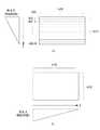
図6は、投影パターンを説明する図である。本実施例では、図6(a)に示すように、投影面の縦方向(Y方向)に漸次明るさが変化し、横方向(X方向)の明るさが一定の第1の投影パターン400と、図6(b)に示すように、投影面の横方向(X方向)に漸次明るさが変化し、縦方向(Y方向)の明るさが一定の第2の投影パターン410を有している。これらの投影パターンは、メモリ350に格納されている。 FIG. 6 is a diagram for explaining the projection pattern. In the present embodiment, as shown in FIG. 6A, the
DMD128が、M行×N列の画素を有しているとき、第1の投影パターン400は、400−1行から400−M行に向けて階調的に明るさが変化するデータ構造である。一方、第2の投影パターン410は、410−1列から410−N列に向けて階調的に明るさが変化するデータ構造である。 When the
投影面における画素の明るさは、DMD128の照射時間に比例する。第1の投影パターン400では、400−1行が最も明るく、そこから徐々に暗くなり、400−M行が最も暗い行となる。DMD128による単位時間当りまたは1フレーム当りの各行の照射時間は、図6(a)に示すように、Y方向に向かうに従い減少する。第2の投影パターン410では、410−1列が最も明るく、そこから徐々に暗くなり、410−N列が最も暗い列となる。DMD128による単位時間当たりの各列の照射時間は、図6(b)に示すように、X方向に向かうにつれ減少する。 The brightness of the pixel on the projection surface is proportional to the irradiation time of the
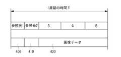
図7は、カラーホイールにより選択された波長と、DMDにより投影される画像データとの関係を示している。カラーホイール116が1回転するときの時間をTとすると、各カラーフィルターの占有する大きさに比例した時間だけ各波長の光が選択される。赤外光フィルター146、148により、波長の異なる参照光1、参照光2が選択され、残りの時間が、R、G、Bの波長の光が選択される。選択された波長の光に同期するようにDMD128が駆動される。すなわち、参照光1が選択されたとき、第1の投影パターン400に基づきDMD128が駆動され、参照光2が選択されたとき、第2の投影パターン410に基づきDMD128が駆動される。R、G、Bが選択されたとき、投影すべき画像データに従いDMD128が駆動される。 FIG. 7 shows the relationship between the wavelength selected by the color wheel and the image data projected by the DMD. If the time when the
図8(a)は、ポインティング装置の構成を示すブロック図である。ポインティング装置200は、ペン状のハウジング210内に、赤外光検出用のセンサー220と、センサー220より検出された信号をディジタル信号に変換するアナログ・ディジタル変換器230と、変換されたディジタル信号から座標位置を算出する算出回路240と、プロジェクタ100にデータを送信する送信回路250と、ハウジング210の先端に筆記部260とを有している。 FIG. 8A is a block diagram illustrating a configuration of the pointing device. The
センサー220は、参照光1の波長を検出する第1のセンサー222と、参照光2の波長を検出する第2のセンサー224を含んでいる。図8(b)は、筆記部260を正面から見た図であるが、図示しない対物レンズを介して第1、第2のセンサー222、224の受光面が併設されている。 The
筆記部260が投射面に当接または近接されたとき、対物レンズを介して一定範囲内の赤外光の検出が行われる。第1、第2のセンサー222、224による検出範囲は、1×1画素領域である。第1のセンサー222は、第1の投影パターンが投影されたとき、筆記部260が位置する画素領域の照射時間を検出し、第2のセンサー224は、第2の投影パターンが投影されたときの画素領域の照射時間を検出する。第1、第2のセンサー222、224によって検出された信号は、アナログ・ディジタル変換器230により2値化され、算出回路240へ供給される。 When the
算出回路240は、第1、第2のセンサーによって検出された信号から、画素領域の照射時間を算出し、これにより、筆記部260の2次元座標位置を算出する。算出回路240は、算出した座標位置を送信回路250へ出力し、送信回路250は、座標位置をプロジェクタ100へ送信する。 The
また、ポインティング装置は、複数の線種、例えば、細線用、中線用、太線用が用意され、かつ、複数の色、例えば、赤、青、黒が用意されている。それぞれのポインティング装置には識別コードが付与されており、送信回路250は、データの送信時に、併せて識別コードを送信する。 The pointing device is prepared for a plurality of line types, for example, for thin lines, for medium lines, and for thick lines, and also has a plurality of colors, for example, red, blue, and black. An identification code is assigned to each pointing device, and the
次に、本実施例のプロジェクタシステムの動作について説明する。ランプ110が点灯され、その光は、回転するカラーホイール116に入射される。カラーホイール116からのR、G、Bの可視光および赤外光による参照光1、2がDMD128を照射する。DMD128は、画像処理回路340により生成された画像データに応答してミラー画素がオン・オフ制御され、このオン・オフ制御は、カラーホイール116の回転に同期して行われる。こうして、投影面上に、画像データが投影される。 Next, the operation of the projector system of this embodiment will be described. The
DMD128はさらに、カラーホイール116の参照光1、2のタイミングに同期して画像処理回路340により生成された第1、第2の投影パターン400、410に応答してミラー画素がオン・オフ制御される。これにより、通常の画像データが投影されている最中に、参照光1、2による投影パターンが投影面に表示される。投影パターンは、カラーホイール116の1回転に付き1回の割合で一定の期間だけ表示されるが、投影パターンは、赤外光による表示であるため、投影面において肉眼により認識されず、投影されている画像に何ら干渉することはない。 In the
一方、ユーザーは、ポインティング装置200を用い、投影面上で文字や図形等の入力を行うことができる。ポインティング装置の筆記部260を投影面上で移動させると、第1、第2のセンサー222、224が、投影面にある投影パターンの明るさを検出する。算出回路240は、第1、第2のセンサー222、224から順次送られてくる検出信号から、筆記部260の座標位置、すなわち移動軌跡を算出する。送信回路250は、算出された座標位置をプロジェクタ100に送信する。 On the other hand, the user can input characters, figures, and the like on the projection surface using the
図9にプロジェクタの動作フローを示す。プロジェクタ100において、データ通信部300がポインティング装置200から時刻t1の座標位置S1(X1、Y1)およびポインティング装置の識別コードを受信すると(ステップS101)、CPU360は、識別コードを解読し、ポインティング装置200の位置、線種、および色を判別する(ステップS102)。 FIG. 9 shows an operation flow of the projector. In
さらにCPU360は、受信した時刻t1の座標位置S1と、一定時間前の時刻t0の座標位置S0(X0、Y0)とを比較し(ステップS103)、差分があるか否かを判定する(ステップS104)。差分があるとき、CPU360は、移動軌跡に対応する画像データを生成し(ステップS105)、画像処理回路340に、投影すべき画像データと、移動軌跡に対応する画像データを合成させる(ステップS106)。 Further, the
次に、CPU360は、合成された画像データに基づきDMD128を駆動させ、投影面に筆記部260の移動軌跡を併せて投影させる(ステップS107)。こうして、ポインティング装置200により描画された文字、図形等の移動軌跡が、投影されている画像に上書きされるかの如く表示される。なお、移動軌跡は、識別されたポインティング装置の線種および色で表示される。一方、ポインティング装置200から一定の期間、座標位置を受信できないとき、あるいは、ポインティング装置200から終了の指示があったとき、CPU360は、画像データの合成および投影を終了する(ステップS108)。 Next, the
このように本実施例によれば、投影面の座標位置を取得するために、簡単なセンサーを用いる以外に、特殊な装置が不要となり、プロジェクタシステムの低コスト化、簡素化を図ることができる。また、第1、第2のセンサー222、224は、画像領域の明るさの強度を測定するのではなく、その照射時間を測定するため、照射距離、強度、センサー面と投射方向の傾きなどによるバラツキを無視することができる。分解能は、主に、測定時間の分解能にのみ依存する。さらに、参照光として赤外光を用いることで、座標位置を表す投影パターンを気にすることなく、可視光による投影用の画像を投影することができる。 As described above, according to the present embodiment, a special device is not required in addition to using a simple sensor to acquire the coordinate position of the projection plane, and the cost and simplification of the projector system can be achieved. . In addition, the first and
次に、本発明の第2の実施例について説明する。図10は、第2の実施例に係るカラーホイールを示す図である。第2の実施例に係るカラーホイールは、参照光1および参照光2を透過する赤外光透過フィルター146、148と、白色光を透過する領域(フィルターなし)149とを備えている。このカラーホイールを用いることで、投影される画像は白黒表示となり、ポインティング装置による移動軌跡は、黒色で表示される。 Next, a second embodiment of the present invention will be described. FIG. 10 is a diagram showing a color wheel according to the second embodiment. The color wheel according to the second embodiment includes infrared light transmission filters 146 and 148 that transmit the
次に、本発明の第3の実施例について説明する。第1の実施例では、ポインティング装置200が、アナログ・ディジタル変換器230、算出回路240を包含する例を示したが、アナログ・ディジタル変換器230および算出回路240をプロジェクタ側に設けるようにしてもよい。この場合、ポインティング装置200によって検出された信号は、送信回路250によってプロジェクタに送信される。プロジェクタは、受信した検出信号をディジタル変換し、その照射時間からポインティング装置の座標位置を算出する。これにより、ポインティング装置側の構成を簡易にし、ポインティング装置の小型化、軽量化、低コスト化を図ることができる。 Next, a third embodiment of the present invention will be described. In the first embodiment, the
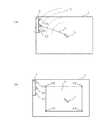
次に、本発明の第4の実施例について説明する。図11(a)は、ポインティング装置の構成を示すブロック図である。第4の実施例では、ポインティング装置に、線種、色の切り替えを行うペン切換回路270が設けられている。ペン切換回路270は、図11(b)に示すように、線種と色の組合せを予めメモリ等に格納しており、選択された線種と色に対応する識別コードを、ポインティング装置の識別コードの代わりに送信するようにする。これにより、ポインティング装置を、線種および色毎に複数用意する必要はなくなる。 Next, a fourth embodiment of the present invention will be described. FIG. 11A is a block diagram illustrating a configuration of the pointing device. In the fourth embodiment, the pointing device is provided with a
さらにポインティング装置は、図11(a)に示すように、ポインティング装置の検出機能を有効または無効にするための入力切替回路280を有するようにしてもよい。入力切替回路280は、例えばユーザーの操作によりオン・オフの選択が可能である。オンが選択されたとき、入力切替回路280は、送信回路250に対して、送信回路250が有効に動作可能であることを示す許可信号を与え、オフが選択されたとき、送信回路250が動作不可であることを示す不許可信号を与える。あるいは、入力切替回路280は、センサー装置220に対して、許可信号または不許可信号を与えるようにしてもよい。 Further, as shown in FIG. 11A, the pointing device may include an
送信無効または検出無効の状態のとき、ポインティング装置200は、通常のマジック等のペンとして実際に投影面(例えば、電子黒板)に文字、図形等を描画できるようにし、送信有効または読取有効の場合にのみ、ポインティング装置の移動軌跡を画像データに合成し、これを投影表示することができる。 When the transmission is invalid or the detection is invalid, the
次に、本発明の第5の実施例について説明する。第5の実施例は、電子黒板の描画面をリアプロジェクタの投影面に適用したものである。図12に示すように、電子黒板500は、文字、図形等を描画する描画面510を有している。さらに、電子黒板500の下部には、プロジェクタ520が接続されている。プロジェクタ520は、画像データを、投影面510に投影するように図2の光学系を構成している。つまり、描画面510は、筆記面および投影面として機能する。プロジェクタにより投影面510に画像を投影している最中に、投影面510上をポインティング装置200を移動させると、その移動軌跡に対応する画像データがプロジェクタにおいて生成され、その画像データが合成されて投影面510に投影される。 Next, a fifth embodiment of the present invention will be described. In the fifth embodiment, the drawing surface of the electronic blackboard is applied to the projection surface of the rear projector. As shown in FIG. 12, the electronic blackboard 500 has a drawing surface 510 for drawing characters, graphics, and the like. Further, a projector 520 is connected to the lower part of the electronic blackboard 500. The projector 520 configures the optical system of FIG. 2 so as to project image data onto the projection surface 510. That is, the drawing surface 510 functions as a writing surface and a projection surface. When the
次に、本発明の第6の実施例について説明する。第1の実施例では、1次元方向に明るさ(濃淡)が変化する第1の投影パターン400と第2の投影パターン410を用いたが、第6の実施例は、2次元方向に明るさ(濃淡)が変化する投影パターンを用いる。すなわち、第1の投影パターンと第2の投影パターンを合成した投影パターンである。第6の実施例では、単一の参照光を用いて投影パターンを投影すればよいため、カラーホイールの赤外光透過フィルターは1つですみ、かつポインティング装置のセンサーも1つでよい。 Next, a sixth embodiment of the present invention will be described. In the first embodiment, the
本発明の好ましい実施の形態について詳述したが、本発明は係る特定の実施形態に限定されるものではなく、特許請求の範囲に記載された本発明の要旨の範囲内において、種々の変形、変更が可能である。 Although the preferred embodiment of the present invention has been described in detail, the present invention is not limited to the specific embodiment, and various modifications, within the scope of the gist of the present invention described in the claims, It can be changed.
上記実施例では、単一のランプからの光をカラーホイールを用いて可視光と赤外光に分割したが、可視光用の光源と別個に、赤外光用の光源を用いるようにしてもよい。この場合、赤外光用の光源からの光を一定のタイミングでDMDを照明するようにすれば、カラーホイールには赤外光透過フィルターを設ける必要はない。そして、第1の実施例と同様に、赤外光がDMD128を照明するタイミングと同期してDMD128に位置情報を投影させる。さらに、単一のDMD128を用いたが、複数のDMDを用いた光学系であってもよい。この場合、一方のDMDは、赤外線による位置情報の表示用に用いるようにすれば、DMDにより常に位置情報が投影面に投影されることになる。さらに、ランプの光源は、放電ランプや、それ以外にも、ダイオードやレーザを用いたものであっても良い。 In the above embodiment, light from a single lamp is divided into visible light and infrared light using a color wheel. However, a light source for infrared light may be used separately from a light source for visible light. Good. In this case, if the DMD is illuminated with light from the light source for infrared light at a fixed timing, it is not necessary to provide an infrared light transmission filter on the color wheel. As in the first embodiment, the position information is projected onto the
さらに上記実施例では、明るさがX方向およびY方向に一様に変化するようにしたが、必ずしもその必要はない。必要な位置、分解能が取り出せる限り、明るさの順番は変更可能である。さらに上記実施例ではセンサーを2つ利用する例を示したが、センサーは1つであってもよい。 Further, in the above embodiment, the brightness is uniformly changed in the X direction and the Y direction, but this is not always necessary. The order of brightness can be changed as long as the necessary position and resolution can be obtained. Furthermore, although the example which uses two sensors was shown in the said Example, the number of sensors may be one.
本発明に係るプロジェクタおよびプロジェクタシステムは、画像や映像などを表示するための入力機能付き表示装置や電子黒板として利用することができる。 The projector and the projector system according to the present invention can be used as a display device with an input function and an electronic blackboard for displaying images and videos.
10:プロジェクタシステム 100:プロジェクタ
110:ランプ 116:カラーホイール
128:DMD 140〜144:カラーフィルター
146、148:赤外光透過フィルター 150:反射ミラー
200:ポインティング装置 210:ハウジング
220:センサー装置 250:送信回路
260:筆記部 400:第1の投影パターン
410:第2の投影パターン 500:電子黒板10: Projector system 100: Projector 110: Lamp 116: Color wheel 128: DMD 140-144:
Claims (15)
Translated fromJapanese可視光の投影動作中に、投影面の位置に応じて明るさが変化する投影パターンを投影する、投影方法。A projection method for projecting position information onto a projection surface projected by a projector,
A projection method for projecting a projection pattern whose brightness changes according to the position of a projection plane during a visible light projection operation.
投影パターンに基づき投影された投影面の所定領域の明るさを検出するステップと、
検出された信号に基づき投影面の前記所定領域の座標位置を算出するステップと、
を有する、請求項1ないし4いずれか1つに記載の位置情報の投影方法。The projection method of position information is further
Detecting the brightness of a predetermined area of the projection surface projected based on the projection pattern;
Calculating a coordinate position of the predetermined area of the projection surface based on the detected signal;
The position information projection method according to claim 1, comprising:
算出された座標位置に基づき画像データを作成するステップと、
作成された画像データと投影用の画像データを合成するステップと、
合成された画像データを投影面に投影するステップと、
を有する、請求項1ないし6いずれか1つに記載の位置情報の投影方法。The projection method of position information is further
Creating image data based on the calculated coordinate position;
Synthesizing the created image data and the image data for projection;
Projecting the synthesized image data onto a projection plane;
The position information projection method according to claim 1, comprising:
光源と、
光源からの光をディジタルマイクロミラーデバイスに照射する照射手段と、
照射された光を変調するディジタルマイクロミラーデバイスと、
ディジタルマイクロミラーデバイスにより変調された光を投影面に投影する投影手段と、
投影面の明るさが2次元的に変化する投影パターンに基づきディジタルマイクロミラーデバイスを駆動する制御手段と、
を有するプロジェクタ。A projector that projects image data on a projection surface,
A light source;
Irradiating means for irradiating the digital micromirror device with light from a light source;
A digital micromirror device that modulates the irradiated light; and
Projection means for projecting light modulated by the digital micromirror device onto a projection surface;
Control means for driving the digital micromirror device based on a projection pattern in which the brightness of the projection surface changes two-dimensionally;
Projector.
プロジェクタとデータ通信が可能なポインティング装置とを有し、
ポインティング装置は、投影パターンに基づき投影された投影面の所定領域の明るさを検出する検出手段と、検出された信号を送信する送信手段とを含み、
プロジェクタは、送信された信号に基づき所定領域に対応する画像データを作成する手段と、作成された画像データと投影用の画像データを合成する手段とを有し、前記制御手段は、合成された画像データに基づきディジタルマイクロミラーデバイスを駆動する、プロジェクタシステム。A projector according to any one of claims 10 to 12,
A pointing device capable of data communication with the projector,
The pointing device includes detection means for detecting the brightness of a predetermined area of the projection surface projected based on the projection pattern, and transmission means for transmitting the detected signal.
The projector has means for creating image data corresponding to a predetermined region based on the transmitted signal, and means for synthesizing the created image data and image data for projection, and the control means A projector system that drives a digital micromirror device based on image data.
Priority Applications (1)
| Application Number | Priority Date | Filing Date | Title |
|---|---|---|---|
| JP2005233325AJP2007048135A (en) | 2005-08-11 | 2005-08-11 | Method for acquiring coordinate position on projection plane using dmd |
Applications Claiming Priority (1)
| Application Number | Priority Date | Filing Date | Title |
|---|---|---|---|
| JP2005233325AJP2007048135A (en) | 2005-08-11 | 2005-08-11 | Method for acquiring coordinate position on projection plane using dmd |
Publications (1)
| Publication Number | Publication Date |
|---|---|
| JP2007048135Atrue JP2007048135A (en) | 2007-02-22 |
Family
ID=37850898
Family Applications (1)
| Application Number | Title | Priority Date | Filing Date |
|---|---|---|---|
| JP2005233325APendingJP2007048135A (en) | 2005-08-11 | 2005-08-11 | Method for acquiring coordinate position on projection plane using dmd |
Country Status (1)
| Country | Link |
|---|---|
| JP (1) | JP2007048135A (en) |
Cited By (15)
| Publication number | Priority date | Publication date | Assignee | Title |
|---|---|---|---|---|
| JP2011039673A (en)* | 2009-08-07 | 2011-02-24 | Sony Corp | Apparatus and method for detecting position |
| JP2011081586A (en)* | 2009-10-07 | 2011-04-21 | Seiko Epson Corp | Projection type display system having position detection function |
| JP2011086029A (en)* | 2009-10-14 | 2011-04-28 | Seiko Epson Corp | Projection type display device with position detection function |
| JP2011090242A (en)* | 2009-10-26 | 2011-05-06 | Seiko Epson Corp | Projection display device with position detecting function |
| JP2011122867A (en)* | 2009-12-09 | 2011-06-23 | Seiko Epson Corp | Optical position detection device and display device with position detection function |
| JP2012003739A (en)* | 2010-06-18 | 2012-01-05 | Nlighten Trading(Shanghai)Co Ltd | Projection type touch control light uniformizing system |
| WO2013111375A1 (en)* | 2012-01-24 | 2013-08-01 | 日本電気株式会社 | Light projection device and method for detecting positional information of projection object |
| JP2013195798A (en)* | 2012-03-21 | 2013-09-30 | Casio Comput Co Ltd | Projection device, projection method and program |
| JP2014010609A (en)* | 2012-06-29 | 2014-01-20 | Casio Comput Co Ltd | Projection device, pointer device and projection system |
| JP2014056115A (en)* | 2012-09-12 | 2014-03-27 | Casio Comput Co Ltd | Display device, projection device, display method and program |
| JP2014062959A (en)* | 2012-09-20 | 2014-04-10 | Casio Comput Co Ltd | Display controller, display device, projection device, pointer device, and system |
| US8714749B2 (en) | 2009-11-06 | 2014-05-06 | Seiko Epson Corporation | Projection display device with position detection function |
| US9141235B2 (en) | 2009-10-26 | 2015-09-22 | Seiko Epson Corporation | Optical position detecting device and display device with position detecting function |
| US9196068B2 (en) | 2012-07-12 | 2015-11-24 | Ricoh Company, Limited | Projector system, and method for drawings |
| JP2017097363A (en)* | 2016-12-22 | 2017-06-01 | カシオ計算機株式会社 | Display device, projection device, display method, and program |
- 2005
- 2005-08-11JPJP2005233325Apatent/JP2007048135A/enactivePending
Cited By (18)
| Publication number | Priority date | Publication date | Assignee | Title |
|---|---|---|---|---|
| JP2011039673A (en)* | 2009-08-07 | 2011-02-24 | Sony Corp | Apparatus and method for detecting position |
| JP2011081586A (en)* | 2009-10-07 | 2011-04-21 | Seiko Epson Corp | Projection type display system having position detection function |
| US8748820B2 (en) | 2009-10-07 | 2014-06-10 | Seiko Epson Corporation | Projection type display system having position detection function |
| JP2011086029A (en)* | 2009-10-14 | 2011-04-28 | Seiko Epson Corp | Projection type display device with position detection function |
| JP2011090242A (en)* | 2009-10-26 | 2011-05-06 | Seiko Epson Corp | Projection display device with position detecting function |
| US9141235B2 (en) | 2009-10-26 | 2015-09-22 | Seiko Epson Corporation | Optical position detecting device and display device with position detecting function |
| US9098137B2 (en) | 2009-10-26 | 2015-08-04 | Seiko Epson Corporation | Position detecting function-added projection display apparatus |
| US8714749B2 (en) | 2009-11-06 | 2014-05-06 | Seiko Epson Corporation | Projection display device with position detection function |
| JP2011122867A (en)* | 2009-12-09 | 2011-06-23 | Seiko Epson Corp | Optical position detection device and display device with position detection function |
| US8847918B2 (en) | 2009-12-09 | 2014-09-30 | Seiko Epson Corporation | Optical position detection device and display device with position detection function |
| JP2012003739A (en)* | 2010-06-18 | 2012-01-05 | Nlighten Trading(Shanghai)Co Ltd | Projection type touch control light uniformizing system |
| WO2013111375A1 (en)* | 2012-01-24 | 2013-08-01 | 日本電気株式会社 | Light projection device and method for detecting positional information of projection object |
| JP2013195798A (en)* | 2012-03-21 | 2013-09-30 | Casio Comput Co Ltd | Projection device, projection method and program |
| JP2014010609A (en)* | 2012-06-29 | 2014-01-20 | Casio Comput Co Ltd | Projection device, pointer device and projection system |
| US9196068B2 (en) | 2012-07-12 | 2015-11-24 | Ricoh Company, Limited | Projector system, and method for drawings |
| JP2014056115A (en)* | 2012-09-12 | 2014-03-27 | Casio Comput Co Ltd | Display device, projection device, display method and program |
| JP2014062959A (en)* | 2012-09-20 | 2014-04-10 | Casio Comput Co Ltd | Display controller, display device, projection device, pointer device, and system |
| JP2017097363A (en)* | 2016-12-22 | 2017-06-01 | カシオ計算機株式会社 | Display device, projection device, display method, and program |
Similar Documents
| Publication | Publication Date | Title |
|---|---|---|
| JP3867205B2 (en) | Pointed position detection device, pointed position detection system, and pointed position detection method | |
| JP5428600B2 (en) | Projector, image projection system, and image projection method | |
| JP2007048135A (en) | Method for acquiring coordinate position on projection plane using dmd | |
| JP5822400B2 (en) | Pointing device with camera and mark output | |
| JP6111706B2 (en) | Position detection apparatus, adjustment method, and adjustment program | |
| EP1132852A1 (en) | Optical coordinate input/detection device with optical-unit positioning error correcting function | |
| JPH1185395A (en) | LCD projector with pointing function | |
| JP2011013396A (en) | Projector, image projection system and image projection method | |
| JP7163943B2 (en) | INFORMATION GENERATION METHOD, INFORMATION GENERATION SYSTEM AND PROGRAM | |
| JP4434381B2 (en) | Coordinate input device | |
| JP2007017516A (en) | Projector provided with function of projecting two-dimensional positional information | |
| JP6167511B2 (en) | Document camera and document camera control method | |
| JP7649715B2 (en) | CONTROL DEVICE, CONTROL METHOD, PROJECTION SYSTEM, AND CONTROL PROGRAM | |
| JP2007048136A (en) | Projector provided with function for projecting two-dimensional position information | |
| JP2010197955A (en) | Display | |
| JP7347205B2 (en) | Projection system control method, projection system and control program | |
| JP5664725B2 (en) | Projector, image projection system, and image projection method | |
| JP2007248939A (en) | Projector with function of projecting two-dimensional positional information | |
| JP2020122696A (en) | Position detection device, position detection unit, image display system, and position detection method | |
| JP2000056925A (en) | Device for changing data on screen in presentation system | |
| JP5061762B2 (en) | Document camera apparatus, image processing method and program | |
| JP2001350585A (en) | Image display device with coordinate input function | |
| JP2007025295A (en) | Projection type display apparatus | |
| JP2008233465A (en) | Projector and projection method of projector | |
| KR20180103630A (en) | Display apparatus and control method thereof |