JP2007041385A - Display device and control method thereof - Google Patents
Display device and control method thereofDownload PDFInfo
- Publication number
- JP2007041385A JP2007041385AJP2005226774AJP2005226774AJP2007041385AJP 2007041385 AJP2007041385 AJP 2007041385AJP 2005226774 AJP2005226774 AJP 2005226774AJP 2005226774 AJP2005226774 AJP 2005226774AJP 2007041385 AJP2007041385 AJP 2007041385A
- Authority
- JP
- Japan
- Prior art keywords
- display
- display panel
- mode
- electrophoretic
- segment
- Prior art date
- Legal status (The legal status is an assumption and is not a legal conclusion. Google has not performed a legal analysis and makes no representation as to the accuracy of the status listed.)
- Withdrawn
Links
- 238000000034methodMethods0.000titleclaimsabstractdescription12
- 239000003086colorantSubstances0.000abstractdescription12
- 239000002245particleSubstances0.000description16
- 239000000758substrateSubstances0.000description9
- 239000003094microcapsuleSubstances0.000description8
- 239000007788liquidSubstances0.000description6
- 101100202858Saccharomyces cerevisiae (strain ATCC 204508 / S288c) SEG2 geneProteins0.000description5
- 239000006185dispersionSubstances0.000description5
- 101150080085SEG1 geneProteins0.000description4
- 101100421134Schizosaccharomyces pombe (strain 972 / ATCC 24843) sle1 geneProteins0.000description4
- 238000001514detection methodMethods0.000description4
- 230000005684electric fieldEffects0.000description4
- 238000010586diagramMethods0.000description3
- 238000007562laser obscuration time methodMethods0.000description3
- 230000010355oscillationEffects0.000description3
- 230000007704transitionEffects0.000description3
- 241001085205Prenanthella exiguaSpecies0.000description2
- 210000001072colonAnatomy0.000description2
- 239000004020conductorSubstances0.000description2
- 239000000725suspensionSubstances0.000description2
- 244000126211Hericium coralloidesSpecies0.000description1
- 230000008021depositionEffects0.000description1
- 238000001962electrophoresisMethods0.000description1
- 239000011521glassSubstances0.000description1
- AMGQUBHHOARCQH-UHFFFAOYSA-Nindium;oxotinChemical compound[In].[Sn]=OAMGQUBHHOARCQH-UHFFFAOYSA-N0.000description1
- 230000014759maintenance of locationEffects0.000description1
- 239000011159matrix materialSubstances0.000description1
- 239000011347resinSubstances0.000description1
- 229920005989resinPolymers0.000description1
- 210000000707wristAnatomy0.000description1
Images


Classifications
- G—PHYSICS
- G09—EDUCATION; CRYPTOGRAPHY; DISPLAY; ADVERTISING; SEALS
- G09G—ARRANGEMENTS OR CIRCUITS FOR CONTROL OF INDICATING DEVICES USING STATIC MEANS TO PRESENT VARIABLE INFORMATION
- G09G3/00—Control arrangements or circuits, of interest only in connection with visual indicators other than cathode-ray tubes
- G09G3/20—Control arrangements or circuits, of interest only in connection with visual indicators other than cathode-ray tubes for presentation of an assembly of a number of characters, e.g. a page, by composing the assembly by combination of individual elements arranged in a matrix no fixed position being assigned to or needed to be assigned to the individual characters or partial characters
- G09G3/34—Control arrangements or circuits, of interest only in connection with visual indicators other than cathode-ray tubes for presentation of an assembly of a number of characters, e.g. a page, by composing the assembly by combination of individual elements arranged in a matrix no fixed position being assigned to or needed to be assigned to the individual characters or partial characters by control of light from an independent source
- G09G3/3433—Control arrangements or circuits, of interest only in connection with visual indicators other than cathode-ray tubes for presentation of an assembly of a number of characters, e.g. a page, by composing the assembly by combination of individual elements arranged in a matrix no fixed position being assigned to or needed to be assigned to the individual characters or partial characters by control of light from an independent source using light modulating elements actuated by an electric field and being other than liquid crystal devices and electrochromic devices
- G09G3/344—Control arrangements or circuits, of interest only in connection with visual indicators other than cathode-ray tubes for presentation of an assembly of a number of characters, e.g. a page, by composing the assembly by combination of individual elements arranged in a matrix no fixed position being assigned to or needed to be assigned to the individual characters or partial characters by control of light from an independent source using light modulating elements actuated by an electric field and being other than liquid crystal devices and electrochromic devices based on particles moving in a fluid or in a gas, e.g. electrophoretic devices
- G—PHYSICS
- G09—EDUCATION; CRYPTOGRAPHY; DISPLAY; ADVERTISING; SEALS
- G09G—ARRANGEMENTS OR CIRCUITS FOR CONTROL OF INDICATING DEVICES USING STATIC MEANS TO PRESENT VARIABLE INFORMATION
- G09G3/00—Control arrangements or circuits, of interest only in connection with visual indicators other than cathode-ray tubes
- G09G3/04—Control arrangements or circuits, of interest only in connection with visual indicators other than cathode-ray tubes for presentation of a single character by selection from a plurality of characters, or by composing the character by combination of individual elements, e.g. segments using a combination of such display devices for composing words, rows or the like, in a frame with fixed character positions
- G09G3/16—Control arrangements or circuits, of interest only in connection with visual indicators other than cathode-ray tubes for presentation of a single character by selection from a plurality of characters, or by composing the character by combination of individual elements, e.g. segments using a combination of such display devices for composing words, rows or the like, in a frame with fixed character positions by control of light from an independent source
- G09G3/19—Control arrangements or circuits, of interest only in connection with visual indicators other than cathode-ray tubes for presentation of a single character by selection from a plurality of characters, or by composing the character by combination of individual elements, e.g. segments using a combination of such display devices for composing words, rows or the like, in a frame with fixed character positions by control of light from an independent source using electrochromic devices
- G—PHYSICS
- G09—EDUCATION; CRYPTOGRAPHY; DISPLAY; ADVERTISING; SEALS
- G09G—ARRANGEMENTS OR CIRCUITS FOR CONTROL OF INDICATING DEVICES USING STATIC MEANS TO PRESENT VARIABLE INFORMATION
- G09G2310/00—Command of the display device
- G09G2310/02—Addressing, scanning or driving the display screen or processing steps related thereto
- G09G2310/0243—Details of the generation of driving signals
- G09G2310/0245—Clearing or presetting the whole screen independently of waveforms, e.g. on power-on
- G—PHYSICS
- G09—EDUCATION; CRYPTOGRAPHY; DISPLAY; ADVERTISING; SEALS
- G09G—ARRANGEMENTS OR CIRCUITS FOR CONTROL OF INDICATING DEVICES USING STATIC MEANS TO PRESENT VARIABLE INFORMATION
- G09G2320/00—Control of display operating conditions
- G09G2320/02—Improving the quality of display appearance
- G09G2320/0233—Improving the luminance or brightness uniformity across the screen
- G—PHYSICS
- G09—EDUCATION; CRYPTOGRAPHY; DISPLAY; ADVERTISING; SEALS
- G09G—ARRANGEMENTS OR CIRCUITS FOR CONTROL OF INDICATING DEVICES USING STATIC MEANS TO PRESENT VARIABLE INFORMATION
- G09G2320/00—Control of display operating conditions
- G09G2320/02—Improving the quality of display appearance
- G09G2320/0242—Compensation of deficiencies in the appearance of colours
- G—PHYSICS
- G09—EDUCATION; CRYPTOGRAPHY; DISPLAY; ADVERTISING; SEALS
- G09G—ARRANGEMENTS OR CIRCUITS FOR CONTROL OF INDICATING DEVICES USING STATIC MEANS TO PRESENT VARIABLE INFORMATION
- G09G2330/00—Aspects of power supply; Aspects of display protection and defect management
- G09G2330/02—Details of power systems and of start or stop of display operation
- G09G2330/021—Power management, e.g. power saving
- G09G2330/022—Power management, e.g. power saving in absence of operation, e.g. no data being entered during a predetermined time
Landscapes
- Engineering & Computer Science (AREA)
- Physics & Mathematics (AREA)
- Computer Hardware Design (AREA)
- General Physics & Mathematics (AREA)
- Theoretical Computer Science (AREA)
- Electrochromic Elements, Electrophoresis, Or Variable Reflection Or Absorption Elements (AREA)
- Control Of Indicators Other Than Cathode Ray Tubes (AREA)
- Electric Clocks (AREA)
Abstract
Translated fromJapaneseDescription
Translated fromJapanese本発明は、電気泳動表示パネルに各種情報を表示する表示装置及びその制御方法に関する。 The present invention relates to a display device that displays various types of information on an electrophoretic display panel and a control method therefor.
近年、液体中に分散した帯電粒子が電界印可により泳動する現象、つまり、電気泳動現象を利用した電気泳動表示パネルを適用した表示装置が提案されている(例えば、特許文献1参照)。この種の表示装置は、電力非供給時でも表示内容を保持する表示保持性を有するため、被駆動時であっても情報を表示し続けることができる。
ところで、上記表示装置では、電池寿命を長くするために、表示パネルの書き換え頻度を下げて消費電力を下げる方法が考えられる。しかしながら、表示装置の仕様(例えば時計仕様)による規制等から、表示パネルの書き換え頻度をある値以下に下げにくく、目的とする電池寿命を確保できない状況がある。その場合に、さらに電池寿命を延ばす方法として、一定条件下で、表示パネルの書き換え頻度を下げるスリープモード(動作低減モード)を設けることが考えられる。 By the way, in the said display apparatus, in order to lengthen battery life, the method of reducing the rewriting frequency of a display panel and reducing power consumption can be considered. However, there are situations where it is difficult to lower the rewrite frequency of the display panel to a certain value or less due to restrictions or the like due to the specifications of the display device (for example, clock specifications), and the target battery life cannot be secured. In that case, as a method for further extending the battery life, it is conceivable to provide a sleep mode (operation reduction mode) for reducing the frequency of rewriting the display panel under a certain condition.
しかし、電気泳動表示パネルは、ある表示色の状態が長時間維持されると、それ以外の色に変化させ難くなる現象がある。例えば、白色と青色の二色の表示を行う電気泳動表示パネルでは、白色の表示領域と青色の表示領域が、その状態に長時間(例えば1時間)保持されると、その後、両方の表示領域を白色に書換駆動しても、書換前が白色の表示領域は鮮やかな白になるのに対し、書換前が青色の表示領域は若干暗い白になってしまう。 However, the electrophoretic display panel has a phenomenon that it is difficult to change to another color when a certain display color state is maintained for a long time. For example, in an electrophoretic display panel that displays two colors, white and blue, if a white display area and a blue display area are held in that state for a long time (for example, 1 hour), then both display areas are displayed. Even if white is rewritten, the white display area becomes bright white before rewriting, whereas the blue display area becomes slightly dark white before rewriting.
このため、スリープモード移行時に白色と青色の表示領域が存在した場合には、通常モードに移行して各表示領域を同色に書換駆動しても、色が不揃いな表示になってしまう問題が生じる。特に、スリープモード移行時に色が異なる表示領域が隣接していた場合には、通常モード移行時に隣接する表示領域の色が不揃いとなってしまうため、その境目が目立ってしまうという問題が生じる。 For this reason, when there are white and blue display areas at the time of transition to the sleep mode, there is a problem that even if the display mode is shifted to the normal mode and each display area is rewritten to the same color, the colors are displayed unevenly. . In particular, when display areas having different colors are adjacent when shifting to the sleep mode, the colors of the adjacent display areas are not uniform when shifting to the normal mode, so that the boundary becomes conspicuous.
本発明は、上述した事情に鑑みてなされたものであり、表示パネルの書換頻度を少なくした動作低減モードから通常モードに移行して画像を表示した場合に、表示色の不揃いを回避することができる表示装置及びその制御方法を提供することにある。 The present invention has been made in view of the above-described circumstances, and it is possible to avoid uneven display colors when an image is displayed by shifting from the operation reduction mode in which the rewriting frequency of the display panel is reduced to the normal mode. An object of the present invention is to provide a display device and a control method thereof.
上述課題を解決するため、本発明は、電気泳動表示パネルを備え、この電気泳動表示パネルに各種情報を表示する表示装置において、前記電気泳動表示パネルに表示される情報を所定の書換間隔で書き換える通常モードと、前記電気泳動表示パネルの書き換えを停止又は書換間隔を長くする動作低減モードとに変更する動作モード変更手段を備え、この動作モード変更手段は、前記動作低減モードに移行する場合に、前記電気泳動表示パネルの予め設定した設定表示領域を略同色に書き換えることを特徴とする。
この発明によれば、動作低減モードに移行する場合に、電気泳動表示パネルの予め設定した設定表示領域を略同色に書き換えるので、通常モードへ移行して電気泳動表示パネルに画像を表示させた場合に表示色の不揃いが生じるのを回避することができる。In order to solve the above-described problems, the present invention includes an electrophoretic display panel, and in a display device that displays various types of information on the electrophoretic display panel, the information displayed on the electrophoretic display panel is rewritten at a predetermined rewrite interval. The operation mode changing means for changing to the normal mode and the operation reduction mode for stopping the rewriting of the electrophoretic display panel or extending the rewrite interval is provided. The preset setting display area of the electrophoretic display panel is rewritten to substantially the same color.
According to the present invention, when shifting to the operation reduction mode, the preset display area of the electrophoretic display panel is rewritten to substantially the same color, so that the mode is shifted to the normal mode and an image is displayed on the electrophoretic display panel. It is possible to avoid the occurrence of uneven display colors.
上記構成において、前記設定表示領域は、前記電気泳動表示パネルの全ての表示領域、又は、通常モード移行時に略同色の画像が表示される表示領域のいずれかであることが好ましい。この構成によれば、通常モード移行時に電気泳動表示パネルの全ての表示領域、又は、略同色の画像が表示される表示領域に色の不揃いが生じる場合を回避することができる。また、上記各構成において、前記電気泳動表示パネルが、セグメント表示パネルであり、前記動作モード変更手段が、動作低減モードに移行する場合に、前記電気泳動表示パネルの表示領域のうち、背景を表示するためのセグメントで仕切られた表示領域単位で、該表示領域内を略同色に書き換えることが好ましい。 In the above configuration, it is preferable that the setting display area is one of all display areas of the electrophoretic display panel or a display area in which an image of substantially the same color is displayed when shifting to the normal mode. According to this configuration, it is possible to avoid a case where color irregularities occur in all the display areas of the electrophoretic display panel or the display area in which an image of substantially the same color is displayed during the transition to the normal mode. In each of the above configurations, when the electrophoretic display panel is a segment display panel and the operation mode changing unit shifts to an operation reduction mode, a background is displayed in the display area of the electrophoretic display panel. It is preferable that the display area is rewritten to substantially the same color in units of display areas partitioned by segments for the purpose.
また、上記各構成において、前記動作モード変更手段が、前記動作低減モードに移行する場合に、前記設定表示領域を通常モード移行時に表示予定の色と略同色に書き換えるようにしてもよい。この場合、通常モード移行時に、設定表示領域に予め予定した色を正確に表示させることができる。また、上記各構成において、前記動作モード変更手段が、前記動作低減モードに移行する場合に、前記設定表示領域に略同色のグラデーションの画像を表示させるようにしてもよい。また、上記各構成において、前記動作モード変更手段は、前記動作低減モードに移行する場合に、前記設定表示領域の色相、明度、彩度の少なくともいずれかが略同一になるように書き換えるようにしてもよい。 In each of the above configurations, when the operation mode changing means shifts to the operation reduction mode, the setting display area may be rewritten to substantially the same color as a color scheduled to be displayed when the normal mode is shifted. In this case, it is possible to accurately display a predetermined color in the setting display area when shifting to the normal mode. In each of the above configurations, when the operation mode changing unit shifts to the operation reduction mode, a gradation image of substantially the same color may be displayed in the setting display area. In each of the above configurations, the operation mode changing unit may rewrite the setting display area so that at least one of hue, brightness, and saturation is substantially the same when the operation reduction mode is entered. Also good.
また、本発明は、電気泳動表示パネルを備え、この電気泳動表示パネルに各種情報を表示する表示装置の制御方法において、前記電気泳動表示パネルに表示される情報を所定の書換間隔で書き換える通常モードから、前記電気泳動表示パネルの書き換えを停止又は書換間隔を長くする動作低減モードに移行する場合に、前記電気泳動表示パネルの予め設定した設定表示領域を略同色に書き換えることを特徴とする。
この発明によれば、動作低減モードに移行する場合に、電気泳動表示パネルの予め設定した設定表示領域を略同色に書き換えるので、通常モードへ移行して電気泳動表示パネルに画像を表示させた場合に表示色の不揃いが生じるのを回避することができる。In addition, the present invention provides a normal mode in which an electrophoretic display panel is provided and information displayed on the electrophoretic display panel is rewritten at a predetermined rewrite interval in a control method for a display device that displays various information on the electrophoretic display panel. Thus, when the operation is shifted to the operation reduction mode in which rewriting of the electrophoretic display panel is stopped or the rewriting interval is extended, the preset setting display area of the electrophoretic display panel is rewritten to substantially the same color.
According to the present invention, when shifting to the operation reduction mode, the preset display area of the electrophoretic display panel is rewritten to substantially the same color, so that the mode is shifted to the normal mode and an image is displayed on the electrophoretic display panel. It is possible to avoid the occurrence of uneven display colors.
本発明は、動作低減モードに移行する場合に、電気泳動表示パネルの予め設定した設定表示領域を略同色に書き換えるので、通常モードへ移行して電気泳動表示パネルに画像を表示させた場合に表示色の不揃いが生じるのを回避することができる。 The present invention rewrites the preset setting display area of the electrophoretic display panel to substantially the same color when shifting to the operation reduction mode, so that the display is performed when shifting to the normal mode and displaying an image on the electrophoretic display panel. It is possible to avoid color irregularities.
以下、図面を参照して本発明の実施形態を詳述する。
(第1実施形態)
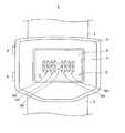
図1は、本発明の第1実施形態に係る腕時計1の外観構成を示す図である。この図に示すように、腕時計1は、時計ケース2と、この時計ケース2に取り付けられ、ユーザの手首に巻き付けられる一対の時計バンド3とを備えている。時計ケース2は正面に時刻を表示するための時刻表示窓4が形成され、時刻を表示する表示パネル5を時刻表示窓4から視認可能に構成されている。また、時刻表示窓4には透明樹脂や透明ガラス等から形成されたカバー体6が嵌め込まれ、このカバー体6により表示パネル5が保護されている。さらに、時計ケース2には、時刻修正やモード変更等の各種指示を行うための操作ボタン8が設けられている。Hereinafter, embodiments of the present invention will be described in detail with reference to the drawings.
(First embodiment)
FIG. 1 is a diagram showing an external configuration of a
上記表示パネル5は、複数のセグメントにより各種情報を表示するセグメント表示パネルが適用され、この表示パネル5の表示領域5Rには、図2に示すように、0〜9の数字を表示するためのセグメント(いわゆる7セグメント)5Aが4列配列され、左2列のセグメント5Aにより時刻の「時」が表示され、右2列のセグメント5Aにより「分」が表示される。また、「時」のセグメント5Aと「分」のセグメント5Aの間には、「時」、「分」の区切りを示す文字(本例ではコロン)を表示するための正面視円形のセグメント5Bが配置されている。
また、同図に示すように、各セグメント5A、5Bには、背景を表示する背景セグメント5Cが各々設けられており、これら背景セグメント5Cにより、各セグメント5A、5Bにより表示される1文字(数字、コロン)毎に、背景(青色又は白色の背景)が表示される。本実施の形態では、この表示パネル5に電気泳動表示パネルが用いられているが、その詳細な構成については後述することにする。また、以下の説明において、セグメント5A〜5Cのそれぞれを特に区別する必要がないときは、セグメント5Xと表記する。The
Further, as shown in the figure, each
上記時計ケース2内には、表示パネル5と一体的に構成された時刻表示ユニット10が配置されている。この時刻表示ユニット10は、図3に断面図を示すように、回路基板11Aと、表示枠11Bと、ディスプレイ基板11Cと、透明基板11Dと、これらを保持する回路押さえ13とを備えている。
ディスプレイ基板11Cは、その上面に、各セグメント5A〜5Cに対応するセグメント電極14と、共通電極用セグメント電極15とが設けられている。
このディスプレイ基板11Cの下面には、表示枠11Bを介して回路基板11Aが配置され、この回路基板11Aには、表示駆動回路40や制御部50等を構成する素子16が実装されている。上記回路基板11Aの上面には、上記素子16(表示駆動回路40等)に配線接続された接点11A1が設けられると共に、上記ディスプレイ基板11Cの下面には、各電極14、15に配線接続された接点11C1が設けられ、これら接点11A1及び11C1は、表示枠11Bを貫通する接続コネクタ17を介して導通されている。A
The
A
さらに、回路基板11Aの側面には、スイッチ用電極18が設けられ、このスイッチ用電極18は、回路押さえ13に設けられた板ばね19を介して導通可能に構成され、この板ばね19が上記操作ボタン8の押下操作によって変形した場合に、この変形した板ばね19を介して導通する。この導通/非導通は、上記素子16(本実施形態では制御部50)によって検出される。また、上記回路基板11Aの下面には、上記素子16に駆動電力を供給する電池(電源)20が着脱自在に設けられる。更に、この回路基板11Aには、上記素子16を覆う回路枠21が固定され、この回路枠21によって素子16が保護されている。なお、上記電池20には、一次電池であるボタン電池が適用されるが、これに限らず、二次電池を適用してもよい。 Further, a
上記透明基板11Dは、ディスプレイ基板11C側の面に、ITO(Indium-Tin Oxide)蒸着等で形成された透明の共通電極25が設けられ、この透明の共通電極25とディスプレイ基板11Cのセグメント電極14との間には、電気泳動層30が設けられ、また、透明の共通電極25と共通電極用セグメント電極15との間には、共通電極用導通材26が介挿されている。この共通電極用導通材26は、例えば、導電性ゴムで形成され、この導電性ゴムが共通電極25と共通電極用セグメント電極15との間の間隙に合わせて変形することにより、これら電極25、15間の導通が確実に確保される。 The
上記電気泳動層30は、図4に示すように、複数のマイクロカプセル31から構成され、これらマイクロカプセル31には、電気泳動粒子32が混合された電気泳動分散液33が封入されている。この電気泳動粒子32には、例えば、プラス極性に帯電した青粒子が適用され、電気泳動分散液33が白色に着色されることにより、いわゆる1粒子系の電気泳動層が構成されている。
従って、表示駆動回路40により共通電極用セグメント電極15(図2)が0V電位(アース電位)に保持されて共通電極25が0V電位とされると共に、所定のセグメント電極14にプラス電圧の駆動電圧が供給されてプラス電位とされた場合、セグメント電極14から共通電極25に向かう電界が発生し、マイクロカプセル31内のプラスに帯電した電気泳動粒子(青粒子)32が共通電極25側に移動し、これに伴って、白色の電気泳動分散液33がセグメント電極14側に移動する。この結果、透明基板11D側から視認されるマイクロカプセル31が青色を呈するため、セグメント5Xが青を表示する。As shown in FIG. 4, the
Accordingly, the common electrode segment electrode 15 (FIG. 2) is held at 0 V potential (ground potential) by the
これとは逆に、表示駆動回路40により共通電極用セグメント電極15にプラス電圧の駆動電圧が供給されて共通電極25がプラス電位とされると共に、所定のセグメント電極14が0V電位に保持された場合には、プラスに帯電した電気泳動粒子(青粒子)32がセグメント電極14側に移動し、これに伴って、白色の電気泳動分散液33が共通電極25側に移動するため、結果として、透明基板11D側から視認されるマイクロカプセル31が白色を呈し、セグメント5Xが白を表示する。また、共通電極25とセグメント電極14との間に電位差を生じない場合には、電気泳動粒子(青粒子)32の移動が生じないため、セグメント5Xの表示色は変化せずに以前の状態が維持される。
なお、本実施の形態では、表示駆動回路40が昇圧回路を内蔵し、電池20から供給される電圧(例えば3V)を昇圧して+12Vの電圧を生成して、この+12Vの電圧、或いは、0Vの電圧を駆動電圧としてセグメント電極14及び共通電極25に印可している。On the other hand, a positive drive voltage is supplied to the common
In the present embodiment, the
図5は、時刻表示ユニット10の電気的構成を示している。
制御部50は、ディスプレイ基板11Cに設けられた配線パターンを介して表示駆動回路40や電池20と電気的に接続され、この制御部50は、計時回路51と、入出力回路(I/O)52と、電圧制御回路53と、操作制御回路54と、低電圧検出回路56と、制御回路(制御手段)57とを備えている。計時回路51は、図示しない発振回路の発振パルスをカウントすることにより時刻を計時するものであり、この計時回路51は、入出力回路52を介して表示駆動回路40と接続されている。
また、電圧制御回路53は、電池20からの供給電力を制御部50内の各部と表示駆動回路40とに供給するものであり、操作制御回路54は、上記スイッチ用電極18の導通/非導通を検出することにより、操作ボタン8の操作を検出し、この検出結果を制御回路57に通知する。FIG. 5 shows an electrical configuration of the
The
The
低電圧検出回路56は、電池20の電圧を検出し、電池電圧が下限閾値を下回ったか否かを判定し、この判定結果を制御回路57に通知するものである。
また、制御回路57は、この時刻表示ユニット10全体を中枢的に制御するものであり、CPU、ROM、RAM等を有し、CPUがROMに記憶された制御プログラムを実行することにより、制御部50の各部の動作を制御すると共に、入出力部(I/O)52を介して表示駆動回路40に各種信号を出力する。
表示駆動回路40は、上記したように、表示パネル5を駆動する回路であり、制御回路57の指示の下、計時回路51により計時されている時刻情報を取得し、指示された書換間隔で表示パネル5の書き換えを行い、時刻を表示パネル5に表示させる。The low
The
As described above, the
ところで、上記制御回路57は、この腕時計1の動作モードを、表示パネル5に表示される時刻情報を時刻の更新間隔(本例では1分間隔)で書き換える通常モード(時刻表示モードに相当)と、表示パネル5の書換間隔を時刻の更新間隔よりも長くするスリープモード(動作低減モード)とに切り替える機能を有している。
この動作モードの切替は、1)ユーザの操作に基づいて切り替える場合、例えば、所定の操作ボタン8の所定操作(短押、長押等)によって動作モードを切り換える、2)予め設定された設定期間になると動作モードを切り替える場合、例えば、午前1:00になるとスリープモードに移行し、午前6:00になると通常モードに移行する、3)電池残量に基づいて切り替える場合、例えば、低電圧検出回路56により電池電圧が下限閾値を下回ると動作低減モードに移行し、電池電圧が上限閾値(下限閾値と同じ値も可)を上回ると通常モードに移行する、の3つの態様があり、いずれか1つ以上の態様が予め設定されている。
なお、上記1)においては、基本がスリープモードの場合も含み、この場合、例えば、操作ボタン8の所定操作があった場合に所定期間の間だけ通常モードに移行し、現在時刻を表示パネル5に表示する。By the way, the
The switching of the operation mode is as follows. 1) When switching based on a user operation, for example, the operation mode is switched by a predetermined operation (short press, long press, etc.) of a
The above 1) includes the case where the basic mode is the sleep mode. In this case, for example, when a predetermined operation of the
次に、通常モード時の動作を説明する。図6は通常モード時の表示制御動作を示すタイミングチャートである。なお、この図においては、制御回路57から表示切替指示信号が出力されたタイミングM1から1分及び2分経過したタイミングをそれぞれタイミングM2、M3と表記する。すなわち、これらのタイミングM2、M3では、制御回路57から表示切替指示信号が表示駆動回路40に対して出力されることになる。また、同図においては、共通電極25に供給される駆動電圧をCOM、2つのセグメント電極14のそれぞれに供給される駆動電圧をSEG1、SEG2と表記し、また、セグメント電極14に供給される各駆動電圧を特に区別する必要のないときは駆動電圧SEGと表記する。さらに、本表示動作の説明においては、2つのセグメント5Xのうちの一方の表示色が青から白に切り替えられ、他方のセグメント5Xの表示色が白から青に切り替えられる場合を説明し、これらのセグメント5Xを互いに区別するために、前者をセグメント5XAと表記し後者をセグメント5XBと表記する。 Next, the operation in the normal mode will be described. FIG. 6 is a timing chart showing the display control operation in the normal mode. In this figure, the timings of 1 minute and 2 minutes from the timing M1 at which the display switching instruction signal is output from the
同図に示すように、表示切替指示信号が表示駆動回路40に入力されてから次の表示切替指示信号が入力されるまでの間の期間には、書換期間Ta及び休止期間Tbが設けられている。書換期間Taは、表示駆動回路40が共通電極25及び各セグメント電極14に対して駆動電圧COM、SEGを供給して各セグメント5Xの表示色を変化させ、時刻表示を切り替える期間である。また、休止期間Tbは、表示駆動回路40が時刻表示切り替え後に、次の表示切替信号が入力されるまで待機する期間であり、この休止期間Tbにおいては、表示駆動回路40はその動作モードを省電力モードとする。また、休止期間Tbにおいては、表示駆動回路40の駆動電圧COM、SEGを出力する出力端がハイインピーダンス状態となる。したがって、休止期間Tbにおいては、共通電極25と各セグメント電極14との間に電位差が生じることがないため、各セグメント5Xの表示色が書換期間Taにおいて変化した色に維持される。 As shown in the figure, a rewrite period Ta and a rest period Tb are provided in a period from when the display switching instruction signal is input to the
この書換期間Taにおいて、本実施の形態では、白から青への表示色の切り替えと、青から白への表示色の切り替えとを同時に行うこととしている。具体的には、表示駆動回路40は、各セグメント5Xのセグメント電極14に対して、そのセグメント5Xが表示すべき表示色(ここでは白或いは青)に応じた電圧の駆動電圧SEGを印加しつつ、電圧が時系列的に表示色のそれぞれに対応した電圧に変化する駆動電圧COMを共通電極25に印加する。
詳述すると、図6に示すように、タイミングM1からタイミングM2までの期間(I)では、書換期間Taにおいて、表示駆動回路40は、表示色を青に変化させるべきセグメント5XAに対して+12Vの駆動電圧SEG1を供給するとともに、表示色を白に変化させるべきセグメント5XBに対して0V(アース電圧)の駆動電圧SEG2を供給する。また、書換期間Taにおいて、表示駆動回路40は共通電極25に対して、駆動電圧COMとして、その電圧がセグメント5Xの表示色を青にするための電圧0V、及び、白にするための電圧+12Vとの間で時系列的に変化する駆動電圧COMを印加する。In the rewriting period Ta, in the present embodiment, switching of the display color from white to blue and switching of the display color from blue to white are performed simultaneously. Specifically, the
More specifically, as shown in FIG. 6, in the period (I) from the timing M1 to the timing M2, in the rewriting period Ta, the
このような駆動電圧COMとして、本実施の形態では、電圧値が+12Vと0Vとの間でくし歯のパルス状に変化する駆動電圧COMが用いられている。このとき、駆動電圧COMの1パルスのパルス幅Wは、図示せぬ発振回路から出力される信号を分周して生成可能な周期(例えば125ms、62.5ms等)に設定されており、この分周信号に基づいて駆動電圧COMを生成可能としている。そして、このパルス幅Wで電圧が+12Vと0Vとの間でくし歯状に変化するパルス列Pの駆動電圧SEGが各セグメント5Xの表示色を変化させるのに十分なパルス数(例えば、+12V、0Vのパルスがそれぞれ10パルス等)だけ印加される。なお、このパルス数(書換期間Ta)を適宜調整することで、各セグメント5Xの表示色が変化した際の反射率(明度)ならびにコントラスト値を調整することができる。 In the present embodiment, a drive voltage COM whose voltage value changes in a comb-like pulse shape between + 12V and 0V is used as such a drive voltage COM. At this time, the pulse width W of one pulse of the drive voltage COM is set to a period (for example, 125 ms, 62.5 ms, etc.) that can be generated by dividing a signal output from an oscillation circuit (not shown). The drive voltage COM can be generated based on the divided signal. The drive voltage SEG of the pulse train P whose voltage changes in a comb-tooth shape between + 12V and 0V with this pulse width W is sufficient to change the display color of each segment 5X (for example, + 12V, 0V). Are applied for 10 pulses each). Note that the reflectance (brightness) and the contrast value when the display color of each segment 5X is changed can be adjusted by appropriately adjusting the number of pulses (rewriting period Ta).
この結果、書換期間Taにおいて、駆動電圧COMの電圧が+12Vのときには、そのパルス幅Wの間、0Vの駆動電圧SEG2が供給されているセグメント5XBのセグメント電極14と共通電極25との間に電界が発生し、マイクロカプセル31の中の青粒子32がセグメント電極14側に移動することで、白色の電気泳動分散液33が共通電極25側に移動し、セグメント5XBの表示色が多少白に変化する。続いて、駆動電圧COMの電圧が0Vになったときには、そのパルス幅Wの間、+12Vの駆動電圧SEG1が供給されているセグメント5XAのセグメント電極14と共通電極25との間に電界が発生し、マイクロカプセル31の中の青粒子32が共通電極25側に引き寄せられることで、セグメント5XAの表示色が多少青に変化する。以降同様にして、駆動電圧COMの電圧の時系列的変化に応じて青粒子32が共通電極25及びセグメント電極14との間で少しずつ順次移動することで、各セグメント5XA、5XBの表示色が段階的に変化し、この書換期間Taの経過時には、セグメント5XAの表示色が青になるともに、セグメント5XBの表示色が白になる。 As a result, in the rewriting period Ta, when the voltage of the drive voltage COM is + 12V, the electric field is generated between the
そして、書換期間Taが経過した後、表示駆動回路40は、次に表示切替信号が入力されるまで待機し、そして、タイミングM2で、再び、表示切替信号が入力された場合には、書換期間Taにおいて、上記と同様にして、各セグメント5XA、5XBの表示色を変化させることになる。例えば、先ほどとは逆に、セグメント5XAの表示色を白に変化させ、また、セグメント5XBの表示色を青に変化させる場合には、表示駆動回路40は、書換期間Taにおいて、セグメント5XAに対して0Vの駆動電圧SEG1を供給するとともに、セグメント5XBに対して+12Vの駆動電圧SEG2を供給し、また、共通電極25に対して、電圧値が+12Vと0Vとの間でくし歯のパルス状に変化する駆動電圧COMを供給することになる。 After the rewriting period Ta has elapsed, the
このように、時刻表示を書き替える書換期間Taにおいて、表示駆動回路40が、セグメント5Xが表示すべき表示色に応じた電圧の駆動電圧SEGを各セグメント5Xのセグメント電極14ごとに印加しつつ、電圧が時系列的に表示色のそれぞれに対応した電圧に変化する駆動電圧COMを共通電極25に印加する構成としたため、この書換期間Ta内で各セグメント5Xが、セグメント電極14に印加された駆動電圧SEGの電圧に応じた表示色へ一斉に変化することとなる。この結果、表示の切り替えの際に、各セグメント5Xの表示色を一旦同じ表示色にする必要が無いため、表示の切り替えを白青同時に行うことができ、自然な切り替え表現とすることができる。以上が通常モード時の動作である。 Thus, in the rewriting period Ta in which the time display is rewritten, the
次にスリープモード時の動作を説明する。図7はスリープモード時の表示制御動作を示すタイミングチャートである。このスリープモード時においては、制御回路57から表示切替指示信号が出力されるタイミングM1、M2、M3…の時間間隔、つまり、表示パネル5の書換間隔が、通常モード時の書換間隔(1分)より長い時間(例えば30分)に設定される。なお、スリープモード時の書換間隔は、上記値に限定されず、例えば、10分や1時間といった値に設定される。 Next, the operation in the sleep mode will be described. FIG. 7 is a timing chart showing the display control operation in the sleep mode. In the sleep mode, the time intervals of the timings M1, M2, M3... At which the display switching instruction signal is output from the
スリープモードに移行する場合、制御回路57は、まず、スリープモードへの移行を指示する信号を表示駆動回路40に出力することにより、表示駆動回路40により表示パネル5の表示領域5R(設定表示領域)を全て白色に書き換える。この場合、図7に示すように、表示駆動回路40は、タイミングM1からタイミングM2までの期間(I)では、書換期間Taにおいて、表示色を白に書き換えるべく、全てのセグメント5X(図示の例ではセグメント5XA、5XBのみを示す)に対して0V(アース電圧)の駆動電圧SEGを供給すると共に、共通電極25に対して、白にするための駆動電圧COMを印可する。この場合の駆動電圧COMのパルス列P1の数は、全てのセグメント5Xを、コントラスト最大の白に変化させるのに十分なパルス数(例えば10パルス)に設定され、これにより、表示パネル5の表示領域5Rが同色に書き換えられる。
ここで、表示領域5Rを同色に書き換えるとは、表示領域5Rの色相、明度、彩度の全てを略同一に書き換える場合に限らず、色相、明度、彩度の少なくとも1つを略同一に書き換える場合を含んでいる。When shifting to the sleep mode, the
Here, the rewriting of the
そして、書換期間Taが経過した後、表示駆動回路40は、次に表示切替信号が入力されるまで待機し、タイミングM2で、再び、表示切替信号が入力された場合には、書換期間Taにおいて、表示パネル5の表示領域5Rを白色に保持すべく、全てのセグメント5Xに対して0V(アース電圧)の駆動電圧SEG2を供給すると共に、共通電極25に対して、白にするための駆動電圧COMを印可する。この場合の駆動電圧COMのパルス列P2の数は、図7に示すように、表示色を同色に保持するのに十分なパルス数に設定され、例えば、2パルスに設定される。 Then, after the rewriting period Ta has elapsed, the
その後、表示駆動回路40は、表示切替信号が入力されたタイミング(M3、…)で、上記タイミングM2の場合と同様にして、表示パネル5の表示領域5R全体を白色に保持する。そして、表示駆動回路40は、制御回路57から通常モードへの移行を指示する信号を入力すると、通常モード時の動作へ移行する。以上がスリープモード時の動作である。このように、本実施の形態によれば、スリープモードの場合には、通常モードに比して、書換間隔が長くなるだけでなく、書換時も通常モードに比して少ないパルス数の駆動電圧COMで書き換えを行うので、この書換駆動に要する電力は少ないものとなり、消費電力を大幅に低減することができ、電池寿命を長くすることができる。 Thereafter, the
以上説明したように、本実施の形態によれば、スリープモード(動作低減モード)へ移行する場合に、表示パネル5の表示領域5R全体を略同色に書き換えるので、ある表示色の状態が長時間維持されるとそれ以外の色に変化させ難くなる現象を持つ電気泳動表示パネルを用いても、その後、通常モードへ移行して表示パネル5に白色や青色の画像を表示させた場合に各色の不揃いが生じるのを回避することができる。
しかも、このスリープモード時においても、表示パネル5の表示領域5R全体を所定周期で白色に書き換えるので、通常モード移行時の画像の色の不揃いをより確実に回避することができる。As described above, according to the present embodiment, when shifting to the sleep mode (operation reduction mode), the
Moreover, even in the sleep mode, the
(第2実施形態)
第2実施形態に係る腕時計1は、スリープモード時に表示パネル5の表示領域を、所定の表示領域単位で同色に書き換える点を除いて、第1実施形態に係る腕時計1と同一である。以下、同一部分については同一の符号を付して説明を省略し、異なる部分を詳細に説明する。
図8は、第2実施形態にかかる腕時計1の表示パネル5を示す図である。この表示パネル5の表示領域50Rは、時刻を表示する時刻表示領域50R1と、暦を表示する暦表示領域50R2(図中、ハッチングを付した領域)とを備えている。(Second Embodiment)
The
FIG. 8 is a diagram showing the
時刻表示領域R1には、「時刻(時分)」を示す0〜9の数字を表示するための4列のセグメント(いわゆる7セグメント)5Aと、「時」と「分」の区切りを示すコロンを表示するセグメント5Bと、各セグメント5A、5Bの背景を表示する背景セグメント5Cとが配置されている。
また、暦表示領域R2には、「暦(月日)」を示す1及び0〜9の数字を表示するための4列のセグメント50Aと、「月」と「日」の区切りを示す文字(本例ではスラッシュ)を表示するセグメント50Bと、各セグメント50A、50Bの背景を表示する背景セグメント50Cとが配置されている。The time display area R1 includes four columns (so-called seven segments) 5A for displaying numbers 0 to 9 indicating "time (hours and minutes)", and a colon indicating a separator between "hours" and "minutes". And a
The calendar display area R2 includes four
この表示パネル5においては、通常モードの場合には、表示駆動回路40により、時計表示領域50R1の背景セグメント5Cが白色とされ、セグメント5A、5Bが現在時刻を示すように選択的に青色と白色とされ、また、暦表示領域50R2の背景セグメント50Cが青色とされ、セグメント50A、50Bが、暦(月日)を示すように選択的に青色と白色とされる。すなわち、現在の時分が白色の背景の中に青色の数字で表示され、現在の月日が、青色の背景の中に白色の数字で表示される。
本実施形態では、計時回路51が時刻と暦を計時する機能を具備しており、表示駆動回路40が、この計時回路51の計時結果を取得し、表示パネル5を分間隔で書換駆動することにより、現在時刻の更新タイミングで表示中の時刻を1分後の時刻に更新すると共に、暦の更新タイミング(例えば、午前0時のタイミング)で、表示中の暦を1日後の暦に更新する。In this
In the present embodiment, the
一方、表示駆動回路40は、制御回路57からスリープモードへの移行を指示する信号を入力すると、予め第1設定表示領域に設定された時計表示領域50R1を全て白色に書き換えると共に、予め第2表示領域に設定された暦表示領域R2を全て青色に書き換える。
そして、上記第1実施形態と同様の書換間隔で、つまり、通常モード時の書換間隔(1分)より長い書換間隔で、その表示状態を保持すべく、その表示状態に書き換える。なお、この表示状態を保持する場合の駆動電圧COMのパルス列P2の数は、第1実施形態と同様に、通常モードに比して少ないパルス数(例えば2パルス)に設定される。そして、表示駆動回路40は、制御回路57から通常モードへの移行を指示する信号を入力すると、通常モード時の動作へ移行する。On the other hand, when the
Then, the display state is rewritten to maintain the display state at the same rewrite interval as in the first embodiment, that is, at a rewrite interval longer than the rewrite interval (1 minute) in the normal mode. Note that the number of pulse trains P2 of the drive voltage COM when this display state is maintained is set to a smaller number of pulses (for example, two pulses) than in the normal mode, as in the first embodiment. The
このように、本実施の形態によれば、スリープモードへ移行する場合に、通常モード時に白色とされる背景セグメント5Cで仕切られた表示領域、つまり、時計表示領域50R1を白色に書き換え、通常モード時に青色とされる背景セグメント50Cで仕切られた表示領域、つまり、暦表示領域50R2を青色に書き換えるので、各表示領域50R1、50R2内における色の不揃いを回避することができる。この結果、時計表示領域50R1及び50R2内の、背景セグメント5C、50Cで仕切られた隣接する表示領域間の境目が色の不揃いにより目立ってしまう場合を確実に回避することができる。
しかも、スリープモード移行時に、各表示領域50R1、50R2を、各々、通常モード移行時に表示予定の色と同色に書き換えるので、通常モード移行時、各表示領域50R1、50R2の背景セグメント5C、50Cに予め予定した色(鮮やかな白色や青色等)を正確に表示させることも可能となる。Thus, according to the present embodiment, when shifting to the sleep mode, the display area partitioned by the
Moreover, since the display areas 50R1 and 50R2 are rewritten to the same colors as the colors scheduled to be displayed when the normal mode is shifted when the sleep mode is shifted, the
上述した実施形態は、あくまで本発明の一態様に過ぎず、本発明の範囲内で任意に変形が可能である。例えば、上述の実施形態では、スリープモード移行時に、表示パネル5の予め設定した設定表示領域を、白色又は青色に書き換える場合について例示したが、中間色でもよく、また、略同色のグラデーションの画像を表示させてもよい。要は、通常モード移行時に色の不揃いを抑制可能な表示画像、すなわち、色変化の少ない表示画像に書き換えればよい。
また、上述の実施形態では、設定表示領域を、表示パネル5の表示領域全体、時刻表示領域及び暦表示領域のいずれかに設定する場合について例示したが、これに限らず、表示パネル5の一部の表示領域でもよく、例えば、通常モード時に連続する模様を表示する一部の表示領域のみを設定表示領域にしてもよい。
また、表示パネル5に複数の情報や画像を表示する場合には、一般に背景セグメントで仕切られた表示領域単位で情報や画像が表示されるため、設定表示領域は、背景セグメントで仕切られた表示領域単位で設定することが好ましい。また、上述の実施形態では、スリープモード時においても、表示パネル5の書き換えを行う場合について述べたが、これに限らず、スリープモード時は表示パネル5の書き換えを停止してもよい。The above-described embodiment is merely one aspect of the present invention, and can be arbitrarily modified within the scope of the present invention. For example, in the above-described embodiment, the case where the preset setting display area of the
In the above-described embodiment, the setting display area is illustrated as being set to any one of the entire display area of the
In addition, when a plurality of information and images are displayed on the
また、上述の実施形態では、表示保持性を有する表示パネル5として、1粒子系の電気泳動表示パネルを適用する場合について例示したが、これに限らず、2粒子系等の電気泳動表示パネルを適用することが可能である。また、表示方式もセグメント方式に限らず、ドットマトリックス方式を適用してもよい。
さらに、上記実施形態では、腕時計に本発明を適用する場合について述べたが、これに限らず、置時計、壁掛時計、柱時計、懐中時計等の各種時計や電子機器等の電気泳動表示パネルを備える表示装置に広く適用することができる。また、時計として構成する場合も、腕時計型に限らず、ネックレス型、指輪型、ペンダント型等の各種形状を適用することができる。In the above-described embodiment, the case where a one-particle electrophoretic display panel is applied as the
Furthermore, although the case where the present invention is applied to a wristwatch has been described in the above embodiment, the present invention is not limited thereto, and includes various types of clocks such as table clocks, wall clocks, wall clocks, pocket watches, and electrophoretic display panels such as electronic devices. It can be widely applied to display devices. Also, when configured as a watch, not only a wristwatch type but also various shapes such as a necklace type, a ring type, and a pendant type can be applied.
1…腕時計、5…表示パネル、5A、5B、5X、50A、50B…セグメント、5C、50C…背景セグメント、5R、50R、50R1、50R2…表示領域(設定表示領域)、10…時刻表示ユニット、11A…回路基板、11B…表示枠、11C…ディスプレイ基板、11D…透明基板、12…透明基板、14…セグメント電極、17…接続コネクタ、20…電池、25…共通電極、26…共通電極用導通材、30…電気泳動層、31…マイクロカプセル、40…表示駆動回路、50…制御部、51…計時回路、52…入出力回路、53…電圧制御回路、54…操作制御回路、57…制御回路(動作モード変更手段)。 DESCRIPTION OF
Claims (7)
Translated fromJapanese前記電気泳動表示パネルに表示される情報を所定の書換間隔で書き換える通常モードと、前記電気泳動表示パネルの書き換えを停止又は書換間隔を長くする動作低減モードとに変更する動作モード変更手段を備え、
この動作モード変更手段は、前記動作低減モードに移行する場合に、前記電気泳動表示パネルの予め設定した設定表示領域を略同色に書き換えることを特徴とする表示装置。In a display device comprising an electrophoretic display panel and displaying various information on the electrophoretic display panel,
Comprising an operation mode changing means for changing to a normal mode in which information displayed on the electrophoretic display panel is rewritten at a predetermined rewriting interval and an operation reducing mode in which rewriting of the electrophoretic display panel is stopped or the rewriting interval is extended,
The operation mode changing means rewrites a preset setting display area of the electrophoretic display panel to substantially the same color when shifting to the operation reduction mode.
前記動作モード変更手段は、前記動作低減モードに移行する場合に、前記電気泳動表示パネルの表示領域のうち、背景を表示するためのセグメントで仕切られた表示領域単位で、該表示領域内を略同色に書き換えることを特徴とする請求項1又は2に記載の表示装置。The electrophoretic display panel is a segment display panel,
When the operation mode changing unit shifts to the operation reduction mode, the display mode of the electrophoretic display panel is displayed in units of display areas divided by segments for displaying a background. The display device according to claim 1, wherein the display device is rewritten to the same color.
前記電気泳動表示パネルに表示される情報を所定の書換間隔で書き換える通常モードから、前記電気泳動表示パネルの書き換えを停止又は書換間隔を長くする動作低減モードに移行する場合に、前記電気泳動表示パネルの予め設定した設定表示領域を略同色に書き換えることを特徴とする表示装置の制御方法。In a control method of a display device comprising an electrophoretic display panel and displaying various information on the electrophoretic display panel,
When shifting from the normal mode in which information displayed on the electrophoretic display panel is rewritten at a predetermined rewrite interval to the operation reduction mode in which rewriting of the electrophoretic display panel is stopped or the rewrite interval is extended, the electrophoretic display panel A method for controlling a display device, wherein the preset setting display area is rewritten to substantially the same color.
Priority Applications (4)
| Application Number | Priority Date | Filing Date | Title |
|---|---|---|---|
| JP2005226774AJP2007041385A (en) | 2005-08-04 | 2005-08-04 | Display device and control method thereof |
| CNA2006101083420ACN1909025A (en) | 2005-08-04 | 2006-08-02 | Display device and control method of the same |
| US11/497,256US20070030243A1 (en) | 2005-08-04 | 2006-08-02 | Display device and control method for the same |
| EP06016329AEP1750242A3 (en) | 2005-08-04 | 2006-08-04 | Electrophoretic display device and control method of the same |
Applications Claiming Priority (1)
| Application Number | Priority Date | Filing Date | Title |
|---|---|---|---|
| JP2005226774AJP2007041385A (en) | 2005-08-04 | 2005-08-04 | Display device and control method thereof |
Publications (2)
| Publication Number | Publication Date |
|---|---|
| JP2007041385Atrue JP2007041385A (en) | 2007-02-15 |
| JP2007041385A5 JP2007041385A5 (en) | 2008-08-28 |
Family
ID=36997560
Family Applications (1)
| Application Number | Title | Priority Date | Filing Date |
|---|---|---|---|
| JP2005226774AWithdrawnJP2007041385A (en) | 2005-08-04 | 2005-08-04 | Display device and control method thereof |
Country Status (4)
| Country | Link |
|---|---|
| US (1) | US20070030243A1 (en) |
| EP (1) | EP1750242A3 (en) |
| JP (1) | JP2007041385A (en) |
| CN (1) | CN1909025A (en) |
Cited By (7)
| Publication number | Priority date | Publication date | Assignee | Title |
|---|---|---|---|---|
| JP2008233318A (en)* | 2007-03-19 | 2008-10-02 | Seiko Epson Corp | Electrophoretic display device, electrophoretic display device driving method, and electronic apparatus |
| JP2008256806A (en)* | 2007-04-02 | 2008-10-23 | Shimadzu Corp | Head-mounted display system |
| JP2009163167A (en)* | 2008-01-10 | 2009-07-23 | Citizen Holdings Co Ltd | Display |
| JP2009186499A (en)* | 2008-02-01 | 2009-08-20 | Seiko Epson Corp | Electrophoretic display device driving method, electrophoretic display device, and electronic apparatus |
| JP2009222901A (en)* | 2008-03-14 | 2009-10-01 | Seiko Epson Corp | Electrophoretic display device driving method, electrophoretic display device, and electronic device |
| JP2011099897A (en)* | 2009-11-04 | 2011-05-19 | Seiko Epson Corp | Driving method of electrophoretic display device, the electrophoretic display device, and electronic apparatus |
| JP2023029000A (en)* | 2021-08-20 | 2023-03-03 | 株式会社リコー | Display device and method for controlling display device |
Families Citing this family (88)
| Publication number | Priority date | Publication date | Assignee | Title |
|---|---|---|---|---|
| JP2009020359A (en)* | 2007-07-12 | 2009-01-29 | Bridgestone Corp | Method of driving panel for information display |
| JP5071014B2 (en)* | 2007-09-13 | 2012-11-14 | セイコーエプソン株式会社 | Electrophoretic display device driving method, electrophoretic display device, and electronic apparatus |
| US9229233B2 (en) | 2014-02-11 | 2016-01-05 | Osterhout Group, Inc. | Micro Doppler presentations in head worn computing |
| US9298007B2 (en) | 2014-01-21 | 2016-03-29 | Osterhout Group, Inc. | Eye imaging in head worn computing |
| US9715112B2 (en) | 2014-01-21 | 2017-07-25 | Osterhout Group, Inc. | Suppression of stray light in head worn computing |
| US9965681B2 (en) | 2008-12-16 | 2018-05-08 | Osterhout Group, Inc. | Eye imaging in head worn computing |
| US9400390B2 (en) | 2014-01-24 | 2016-07-26 | Osterhout Group, Inc. | Peripheral lighting for head worn computing |
| US9952664B2 (en) | 2014-01-21 | 2018-04-24 | Osterhout Group, Inc. | Eye imaging in head worn computing |
| JP2011013660A (en)* | 2009-06-04 | 2011-01-20 | Seiko Epson Corp | Display apparatus |
| US20110234557A1 (en)* | 2010-03-26 | 2011-09-29 | Chang-Jing Yang | Electrophoretic display device and method for driving same |
| JP2013156392A (en)* | 2012-01-30 | 2013-08-15 | Semiconductor Components Industries Llc | Driving circuit for electrophoretic display device |
| US10254856B2 (en) | 2014-01-17 | 2019-04-09 | Osterhout Group, Inc. | External user interface for head worn computing |
| US20150228119A1 (en) | 2014-02-11 | 2015-08-13 | Osterhout Group, Inc. | Spatial location presentation in head worn computing |
| US9841599B2 (en) | 2014-06-05 | 2017-12-12 | Osterhout Group, Inc. | Optical configurations for head-worn see-through displays |
| US9529195B2 (en) | 2014-01-21 | 2016-12-27 | Osterhout Group, Inc. | See-through computer display systems |
| US9594246B2 (en) | 2014-01-21 | 2017-03-14 | Osterhout Group, Inc. | See-through computer display systems |
| US9829707B2 (en) | 2014-08-12 | 2017-11-28 | Osterhout Group, Inc. | Measuring content brightness in head worn computing |
| US9671613B2 (en) | 2014-09-26 | 2017-06-06 | Osterhout Group, Inc. | See-through computer display systems |
| US9810906B2 (en) | 2014-06-17 | 2017-11-07 | Osterhout Group, Inc. | External user interface for head worn computing |
| US11227294B2 (en) | 2014-04-03 | 2022-01-18 | Mentor Acquisition One, Llc | Sight information collection in head worn computing |
| US10191279B2 (en) | 2014-03-17 | 2019-01-29 | Osterhout Group, Inc. | Eye imaging in head worn computing |
| US20160147063A1 (en)* | 2014-11-26 | 2016-05-26 | Osterhout Group, Inc. | See-through computer display systems |
| US9746686B2 (en) | 2014-05-19 | 2017-08-29 | Osterhout Group, Inc. | Content position calibration in head worn computing |
| US10649220B2 (en) | 2014-06-09 | 2020-05-12 | Mentor Acquisition One, Llc | Content presentation in head worn computing |
| US9299194B2 (en) | 2014-02-14 | 2016-03-29 | Osterhout Group, Inc. | Secure sharing in head worn computing |
| US10684687B2 (en) | 2014-12-03 | 2020-06-16 | Mentor Acquisition One, Llc | See-through computer display systems |
| US9939934B2 (en) | 2014-01-17 | 2018-04-10 | Osterhout Group, Inc. | External user interface for head worn computing |
| US11103122B2 (en) | 2014-07-15 | 2021-08-31 | Mentor Acquisition One, Llc | Content presentation in head worn computing |
| US20160019715A1 (en) | 2014-07-15 | 2016-01-21 | Osterhout Group, Inc. | Content presentation in head worn computing |
| US9575321B2 (en) | 2014-06-09 | 2017-02-21 | Osterhout Group, Inc. | Content presentation in head worn computing |
| JP6447802B2 (en)* | 2014-01-20 | 2019-01-09 | セイコーエプソン株式会社 | Electrophoretic display device, electronic timepiece, wristwatch, and operation method of electrophoretic display device |
| US9753288B2 (en) | 2014-01-21 | 2017-09-05 | Osterhout Group, Inc. | See-through computer display systems |
| US9836122B2 (en) | 2014-01-21 | 2017-12-05 | Osterhout Group, Inc. | Eye glint imaging in see-through computer display systems |
| US9494800B2 (en) | 2014-01-21 | 2016-11-15 | Osterhout Group, Inc. | See-through computer display systems |
| US9811152B2 (en) | 2014-01-21 | 2017-11-07 | Osterhout Group, Inc. | Eye imaging in head worn computing |
| US9651788B2 (en) | 2014-01-21 | 2017-05-16 | Osterhout Group, Inc. | See-through computer display systems |
| US9651784B2 (en) | 2014-01-21 | 2017-05-16 | Osterhout Group, Inc. | See-through computer display systems |
| US20150205135A1 (en) | 2014-01-21 | 2015-07-23 | Osterhout Group, Inc. | See-through computer display systems |
| US9615742B2 (en) | 2014-01-21 | 2017-04-11 | Osterhout Group, Inc. | Eye imaging in head worn computing |
| US11892644B2 (en) | 2014-01-21 | 2024-02-06 | Mentor Acquisition One, Llc | See-through computer display systems |
| US11487110B2 (en) | 2014-01-21 | 2022-11-01 | Mentor Acquisition One, Llc | Eye imaging in head worn computing |
| US11737666B2 (en) | 2014-01-21 | 2023-08-29 | Mentor Acquisition One, Llc | Eye imaging in head worn computing |
| US9740280B2 (en) | 2014-01-21 | 2017-08-22 | Osterhout Group, Inc. | Eye imaging in head worn computing |
| US12093453B2 (en) | 2014-01-21 | 2024-09-17 | Mentor Acquisition One, Llc | Eye glint imaging in see-through computer display systems |
| US11669163B2 (en) | 2014-01-21 | 2023-06-06 | Mentor Acquisition One, Llc | Eye glint imaging in see-through computer display systems |
| US9766463B2 (en) | 2014-01-21 | 2017-09-19 | Osterhout Group, Inc. | See-through computer display systems |
| US9846308B2 (en) | 2014-01-24 | 2017-12-19 | Osterhout Group, Inc. | Haptic systems for head-worn computers |
| US9401540B2 (en) | 2014-02-11 | 2016-07-26 | Osterhout Group, Inc. | Spatial location presentation in head worn computing |
| US9852545B2 (en) | 2014-02-11 | 2017-12-26 | Osterhout Group, Inc. | Spatial location presentation in head worn computing |
| US12112089B2 (en) | 2014-02-11 | 2024-10-08 | Mentor Acquisition One, Llc | Spatial location presentation in head worn computing |
| US20160187651A1 (en) | 2014-03-28 | 2016-06-30 | Osterhout Group, Inc. | Safety for a vehicle operator with an hmd |
| US10853589B2 (en) | 2014-04-25 | 2020-12-01 | Mentor Acquisition One, Llc | Language translation with head-worn computing |
| US9672210B2 (en) | 2014-04-25 | 2017-06-06 | Osterhout Group, Inc. | Language translation with head-worn computing |
| US9651787B2 (en) | 2014-04-25 | 2017-05-16 | Osterhout Group, Inc. | Speaker assembly for headworn computer |
| TWI521337B (en)* | 2014-05-06 | 2016-02-11 | 巨擘科技股份有限公司 | Timepiece and power saving method thereof |
| JP6769868B2 (en)* | 2014-05-30 | 2020-10-14 | ソニー株式会社 | Mobile wear and communication system |
| US10663740B2 (en) | 2014-06-09 | 2020-05-26 | Mentor Acquisition One, Llc | Content presentation in head worn computing |
| KR102511376B1 (en) | 2014-08-02 | 2023-03-17 | 애플 인크. | Context-specific user interfaces |
| US10452253B2 (en) | 2014-08-15 | 2019-10-22 | Apple Inc. | Weather user interface |
| US9684172B2 (en) | 2014-12-03 | 2017-06-20 | Osterhout Group, Inc. | Head worn computer display systems |
| USD751552S1 (en) | 2014-12-31 | 2016-03-15 | Osterhout Group, Inc. | Computer glasses |
| USD753114S1 (en) | 2015-01-05 | 2016-04-05 | Osterhout Group, Inc. | Air mouse |
| US10878775B2 (en) | 2015-02-17 | 2020-12-29 | Mentor Acquisition One, Llc | See-through computer display systems |
| US20160239985A1 (en) | 2015-02-17 | 2016-08-18 | Osterhout Group, Inc. | See-through computer display systems |
| WO2016144385A1 (en) | 2015-03-08 | 2016-09-15 | Apple Inc. | Sharing user-configurable graphical constructs |
| JP2016191848A (en)* | 2015-03-31 | 2016-11-10 | セイコーエプソン株式会社 | Electro-optical display device, electronic apparatus, and driving method |
| CN107921317B (en) | 2015-08-20 | 2021-07-06 | 苹果公司 | Movement-based watch faces and complications |
| US10269309B2 (en) | 2015-10-05 | 2019-04-23 | Microsoft Technology Licensing, Llc | Persistent display device with power harvesting |
| US10591728B2 (en) | 2016-03-02 | 2020-03-17 | Mentor Acquisition One, Llc | Optical systems for head-worn computers |
| US10667981B2 (en) | 2016-02-29 | 2020-06-02 | Mentor Acquisition One, Llc | Reading assistance system for visually impaired |
| CN109564456A (en)* | 2016-04-28 | 2019-04-02 | 尤塔设备Ipr有限公司 | Notification method |
| US12175065B2 (en) | 2016-06-10 | 2024-12-24 | Apple Inc. | Context-specific user interfaces for relocating one or more complications in a watch or clock interface |
| KR102208257B1 (en) | 2016-09-23 | 2021-01-27 | 애플 인크. | Watch theater mode |
| DK179412B1 (en) | 2017-05-12 | 2018-06-06 | Apple Inc | Context-Specific User Interfaces |
| DK179555B1 (en) | 2017-05-16 | 2019-02-13 | Apple Inc. | User interface for a flashlight mode on an electronic device |
| US11327650B2 (en) | 2018-05-07 | 2022-05-10 | Apple Inc. | User interfaces having a collection of complications |
| US11131967B2 (en) | 2019-05-06 | 2021-09-28 | Apple Inc. | Clock faces for an electronic device |
| US11960701B2 (en) | 2019-05-06 | 2024-04-16 | Apple Inc. | Using an illustration to show the passing of time |
| JP6921338B2 (en) | 2019-05-06 | 2021-08-18 | アップル インコーポレイテッドApple Inc. | Limited operation of electronic devices |
| US10852905B1 (en) | 2019-09-09 | 2020-12-01 | Apple Inc. | Techniques for managing display usage |
| US11526256B2 (en) | 2020-05-11 | 2022-12-13 | Apple Inc. | User interfaces for managing user interface sharing |
| US11372659B2 (en) | 2020-05-11 | 2022-06-28 | Apple Inc. | User interfaces for managing user interface sharing |
| DK202070624A1 (en) | 2020-05-11 | 2022-01-04 | Apple Inc | User interfaces related to time |
| US11694590B2 (en) | 2020-12-21 | 2023-07-04 | Apple Inc. | Dynamic user interface with time indicator |
| US11720239B2 (en) | 2021-01-07 | 2023-08-08 | Apple Inc. | Techniques for user interfaces related to an event |
| US12182373B2 (en) | 2021-04-27 | 2024-12-31 | Apple Inc. | Techniques for managing display usage |
| US11921992B2 (en) | 2021-05-14 | 2024-03-05 | Apple Inc. | User interfaces related to time |
| US20230236547A1 (en) | 2022-01-24 | 2023-07-27 | Apple Inc. | User interfaces for indicating time |
Family Cites Families (10)
| Publication number | Priority date | Publication date | Assignee | Title |
|---|---|---|---|---|
| US4041481A (en)* | 1974-10-05 | 1977-08-09 | Matsushita Electric Industrial Co., Ltd. | Scanning apparatus for an electrophoretic matrix display panel |
| US4746917A (en) | 1986-07-14 | 1988-05-24 | Copytele, Inc. | Method and apparatus for operating an electrophoretic display between a display and a non-display mode |
| EP0256879B1 (en) | 1986-08-18 | 1993-07-21 | Canon Kabushiki Kaisha | Display device |
| JP4470232B2 (en)* | 1999-03-31 | 2010-06-02 | コニカミノルタホールディングス株式会社 | Information display device |
| JP5025070B2 (en)* | 2000-09-27 | 2012-09-12 | シチズンホールディングス株式会社 | Electronic clock |
| JP4061863B2 (en)* | 2001-06-20 | 2008-03-19 | 富士ゼロックス株式会社 | Image display device and display driving method |
| US20030016590A1 (en)* | 2001-07-19 | 2003-01-23 | Brewer Donald R. | Timepiece module with bi-stable display |
| JP4615860B2 (en) | 2001-11-20 | 2011-01-19 | イー インク コーポレイション | Multi-stable electro-optical display driving method, device controller, and multi-stable electro-optical display |
| US7202847B2 (en)* | 2002-06-28 | 2007-04-10 | E Ink Corporation | Voltage modulated driver circuits for electro-optic displays |
| EP1656658A4 (en)* | 2003-08-19 | 2009-12-30 | E Ink Corp | Methods for controlling electro-optic displays |
- 2005
- 2005-08-04JPJP2005226774Apatent/JP2007041385A/ennot_activeWithdrawn
- 2006
- 2006-08-02USUS11/497,256patent/US20070030243A1/ennot_activeAbandoned
- 2006-08-02CNCNA2006101083420Apatent/CN1909025A/enactivePending
- 2006-08-04EPEP06016329Apatent/EP1750242A3/ennot_activeWithdrawn
Cited By (11)
| Publication number | Priority date | Publication date | Assignee | Title |
|---|---|---|---|---|
| JP2008233318A (en)* | 2007-03-19 | 2008-10-02 | Seiko Epson Corp | Electrophoretic display device, electrophoretic display device driving method, and electronic apparatus |
| JP2008256806A (en)* | 2007-04-02 | 2008-10-23 | Shimadzu Corp | Head-mounted display system |
| JP2009163167A (en)* | 2008-01-10 | 2009-07-23 | Citizen Holdings Co Ltd | Display |
| JP2009186499A (en)* | 2008-02-01 | 2009-08-20 | Seiko Epson Corp | Electrophoretic display device driving method, electrophoretic display device, and electronic apparatus |
| US8749477B2 (en) | 2008-02-01 | 2014-06-10 | Seiko Epson Corporation | Method of driving electrophoretic display device, electrophoretic display device, and electronic apparatus |
| KR101555711B1 (en)* | 2008-02-01 | 2015-09-25 | 세이코 엡슨 가부시키가이샤 | A method of driving an electrophoretic display device, an electrophoretic display device, and an electronic device |
| JP2009222901A (en)* | 2008-03-14 | 2009-10-01 | Seiko Epson Corp | Electrophoretic display device driving method, electrophoretic display device, and electronic device |
| KR101512520B1 (en) | 2008-03-14 | 2015-04-15 | 세이코 엡슨 가부시키가이샤 | Driving method of electrophoretic display device, electrophoretic display device, and electronic apparatus |
| JP2011099897A (en)* | 2009-11-04 | 2011-05-19 | Seiko Epson Corp | Driving method of electrophoretic display device, the electrophoretic display device, and electronic apparatus |
| JP2023029000A (en)* | 2021-08-20 | 2023-03-03 | 株式会社リコー | Display device and method for controlling display device |
| JP7732274B2 (en) | 2021-08-20 | 2025-09-02 | 株式会社リコー | Display device, display device control method and program |
Also Published As
| Publication number | Publication date |
|---|---|
| CN1909025A (en) | 2007-02-07 |
| EP1750242A3 (en) | 2008-01-16 |
| EP1750242A2 (en) | 2007-02-07 |
| US20070030243A1 (en) | 2007-02-08 |
Similar Documents
| Publication | Publication Date | Title |
|---|---|---|
| JP2007041385A (en) | Display device and control method thereof | |
| JP4867247B2 (en) | Display device, driving device, and driving method | |
| US20070080928A1 (en) | Display control apparatus, display device, and control method for a display device | |
| US8044927B2 (en) | Drive method for a display device, drive device, display device, and electronic device | |
| KR100930138B1 (en) | Method of driving display device, driving device, display device and electronic device | |
| JP4985113B2 (en) | Electrophoretic display panel driving method and driving device, electrophoretic display device, and electronic apparatus | |
| JP6866584B2 (en) | Display device, display control method and program | |
| US6429840B1 (en) | Method of driving color liquid crystal display panel and method of controlling display of timepiece | |
| EP1750182A1 (en) | Display device and control method for the same | |
| US9564087B2 (en) | Electrophoretic display device, electronic timepiece, and operating method of an electrophoretic display device | |
| JP2008139163A (en) | Display device and display method | |
| US8254211B2 (en) | Electronic device and control method therefor | |
| JP2008145173A (en) | Display device | |
| JP5176326B2 (en) | Electrophoretic display panel driving method and driving device, electrophoretic display device, and electronic apparatus | |
| JP2012189531A (en) | Electronic clock | |
| JP5402145B2 (en) | Time display device and driving method of time display device | |
| HK1103841A (en) | Electrophoretic display device and control method of the same | |
| HK1103812A (en) | Display device and control method for the same |
Legal Events
| Date | Code | Title | Description |
|---|---|---|---|
| A521 | Written amendment | Free format text:JAPANESE INTERMEDIATE CODE: A821 Effective date:20080630 | |
| RD04 | Notification of resignation of power of attorney | Free format text:JAPANESE INTERMEDIATE CODE: A7424 Effective date:20080630 | |
| A521 | Written amendment | Free format text:JAPANESE INTERMEDIATE CODE: A523 Effective date:20080710 | |
| A621 | Written request for application examination | Free format text:JAPANESE INTERMEDIATE CODE: A621 Effective date:20080710 | |
| RD03 | Notification of appointment of power of attorney | Free format text:JAPANESE INTERMEDIATE CODE: A7423 Effective date:20080710 | |
| A761 | Written withdrawal of application | Free format text:JAPANESE INTERMEDIATE CODE: A761 Effective date:20100412 |