JP2007036482A - Information projection display device and program - Google Patents
Information projection display device and programDownload PDFInfo
- Publication number
- JP2007036482A JP2007036482AJP2005214827AJP2005214827AJP2007036482AJP 2007036482 AJP2007036482 AJP 2007036482AJP 2005214827 AJP2005214827 AJP 2005214827AJP 2005214827 AJP2005214827 AJP 2005214827AJP 2007036482 AJP2007036482 AJP 2007036482A
- Authority
- JP
- Japan
- Prior art keywords
- projection
- image
- homography
- unit
- plane
- Prior art date
- Legal status (The legal status is an assumption and is not a legal conclusion. Google has not performed a legal analysis and makes no representation as to the accuracy of the status listed.)
- Pending
Links
Images


Landscapes
- Transforming Electric Information Into Light Information (AREA)
- Control Of Indicators Other Than Cathode Ray Tubes (AREA)
- Controls And Circuits For Display Device (AREA)
- Projection Apparatus (AREA)
Abstract
Description
Translated fromJapanese本発明は、各種情報を実空間の平面上への投影表示するための装置に関する。 The present invention relates to an apparatus for projecting and displaying various types of information on a plane in real space.
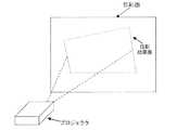
画像情報を投影表示するには、市販のプロジェクタを用いる方法が一般的である。しかし、矩形画像をスクリーン(投影面)に対して斜め方向から投影すると、結果の像は矩形とはならず、図2に示したような台形歪みが生じてしまう。このような歪みを補正するための自動台形歪補正機能がついている市販のプロジェクタも存在する。これらは、投影面正面に対し、下方または上方から投影した場合にのみ歪補正を行なうものがほとんどで、横方向から投影した場合の歪補正には対応していない。例えば、エプソンのEMP821(http://www.i-love-epson.co.jp/products/offirio/emp/emp81_61/index.htm)には縦方向の自動歪補正機能がついている。これは、プロジェクタを置いた場合の本体の傾きをセンサーで検知し、床面に対して垂直に置かれた投影スクリーンに対し、無歪となるように投影する機能である。この場合、カタログスペックでは、歪補正可能なプロジェクタの配置傾き角は、±4°〜±30°となっている。このように、歪補正に対応している場合でもプロジェクタと投影面との位置関係には制約があった。 In order to project and display image information, a method using a commercially available projector is generally used. However, when a rectangular image is projected on the screen (projection plane) from an oblique direction, the resulting image does not become rectangular, and trapezoidal distortion as shown in FIG. 2 occurs. Some commercially available projectors have an automatic trapezoidal distortion correction function for correcting such distortion. Most of these perform distortion correction only when projected from below or above the front of the projection surface, and do not correspond to distortion correction when projected from the lateral direction. For example, Epson's EMP821 (http://www.i-love-epson.co.jp/products/offirio/emp/emp81_61/index.htm) has a vertical automatic distortion correction function. This is a function of detecting the tilt of the main body when the projector is placed with a sensor and projecting the projection screen placed perpendicular to the floor surface without distortion. In this case, according to the catalog specification, the arrangement inclination angle of the projector capable of correcting distortion is ± 4 ° to ± 30 °. As described above, even when the distortion correction is supported, the positional relationship between the projector and the projection surface is limited.
一方、以下に示す非特許文献1と2では、投影面をカメラで撮影し、その撮影画像に画像処理を行なうことで無歪投影を実現する手法も提案されている。これらの方法では、画像処理の分野では一般に知られているホモグラフィの考えを用いており、原理上プロジェクタと投影面との位置関係の制約は無いという利点がある。 On the other hand, Non-Patent
以下、ホモグラフィについて簡単に説明する。 Hereinafter, homography will be briefly described.
ある平面をカメラで撮影した場合、その平面上の特徴点 When a plane is shot with a camera, feature points on that plane

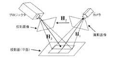
以上は、撮影画像と撮影平面との間のホモグラフィに関する考えだが、これは射影変換の関係がある平面間に適用できることが一般にも知られている。例えば、今、プロジェクタで投影面上に投影した投影表示結果をカメラで撮影するとした時、投影面と撮影画像の間、投影画像と投影面の間のホモグラフィをそれぞれ The above is the idea about the homography between the photographed image and the photographing plane, but it is generally known that this can be applied between the planes having a projective transformation relationship. For example, when the projection display result projected on the projection plane by the projector is now shot by the camera, the homography between the projection plane and the shot image, and the homography between the projection image and the projection plane, respectively.
次に、非特許文献について説明する。 Next, non-patent literature will be described.
まず、Sukthankarらの非特許文献1では、主にプレゼンテーションでの利用を対象に、投影面を一般的なプロジェクタ用スクリーンであるとし、それに対して任意の場所においたプロジェクタからの投影結果をカメラで撮影し、その結果をもとに、無歪投影を実現する方法を提案している。そこでは、上で説明した3つのホモグラフィの関係を用いて投影画像と投影面の間のホモグラフィを求め、そのホモグラフィを変換行列として変換した画像を投影し、無歪投影を実現している。この方法では、そのスクリーンのエッジを測定することによって得られる対応点関係から投影面と撮影画像との間のホモグラフィを求めている。また、スクリーン枠の大きさに合わせて投影領域を決定している。すなわち、カメラとスクリーン(投影面)の位置関係に制約があり、かつ撮影画像からスクリーンのエッジが観測できなければならないという環境上の制約もあった。 First, in Non-Patent
また、Raskerらの非特許文献2では、地面に対して垂直に置かれた投影面に対し、無歪投影表示を実現する手法を提案している。この手法では、カメラとプロジェクタの位置関係は既知で、かつ固定であることを前提としている。そのためカメラとプロジェクタのキャリブレーション値をあらかじめ測定することができ、それを用いてプロジェクタから投影したパターンをカメラで撮影した時の対応関係を観測することにより、投影画像と投影面との間のホモグラフィを求めている。そのため、この方法では、撮影画像上に投影パターン全体が映っていればよかった。また、パターンは自由に投影できるため、パターンの色を工夫すれば、環境によらずに対応点を観測しやすいという利点もあった。さらに、投影領域は、投影可能な領域の枠をプロジェクタから投影し、それをカメラで観測することにより決定していた。この際には、傾斜計で地面に対するプロジェクタの傾きを測定し、床面に対して垂直に置かれている平面な投影面上に、床面に対し上辺と底辺が平行となるように投影されるようにしていた。
しかしながら、上記従来の方法は、以下に示す問題があった。
1.市販のプロジェクタでは、置ける位置に制限があり、表示領域をユーザが自由に指定することが難しかった。
2.Sukthankarらの方法は、スクリーンを用いたプレゼンテーションに使用することを目的としているため、投影領域をスクリーン枠に合うように決定しており、固定のスクリーン枠全体が自動認識可能な枠として、カメラ画像中に撮影されている必要があった。
3.Raskerらの方法では、プロジェクタから投影したパターンの枠をもとに投影領域を決定しており、あらかじめ固定の投影枠を用意しておく必要はないが、パターン形状を変えながらユーザが自分の好きな投影領域を直感的に指定することは困難であった。However, the conventional method has the following problems.
1. In a commercially available projector, there are restrictions on the position where it can be placed, and it is difficult for the user to freely specify the display area.
2. The method of Suktankar et al. Is intended to be used for presentations using a screen, so the projection area is determined so as to fit the screen frame, and the camera screen image is used as a frame that can be automatically recognized by the entire fixed screen frame. It was necessary to be filmed inside.
3. In the method of Rasker et al., The projection area is determined based on the pattern frame projected from the projector, and it is not necessary to prepare a fixed projection frame in advance. It is difficult to intuitively specify a proper projection area.
本発明の目的は、任意の場所から任意の方向にある投影面上に無歪み投影ができ、かつ簡単、直感的に投影領域を指定することが可能な情報投影表示装置およびプログラムを提供することである。 An object of the present invention is to provide an information projection display device and program capable of performing distortion-free projection on a projection surface in an arbitrary direction from an arbitrary location and easily and intuitively specifying a projection area. It is.
上記目的を達成するために、本発明の投影表示装置は投影パターン生成部とプロジェクション部と撮影部とホモグラフィ算出部と投影領域決定部と画像変換部を有する。 In order to achieve the above object, the projection display apparatus of the present invention includes a projection pattern generation unit, a projection unit, a photographing unit, a homography calculation unit, a projection region determination unit, and an image conversion unit.
投影パターン生成部で生成したパターンをプロジェクション部で投影面に投影し、その投影結果の像を撮影部で撮影する。上記投影パターン像と撮影画像との対応関係から、投影画像と投影面との間のホモグラフィをホモグラフィ算出部にて計算する。投影領域決定部で、投影面上にユーザが置くマーカの位置を画像処理で認識し、その位置から、投影画像と縦横比が同じになるような投影領域を決定する。画像変換部では、上記で求めた投影領域上に投影されるように、ホモグラフィを用いて投影画像を変換し、その変換後画像をプロジェクション部から投影する。これにより無歪投影を実現する。 A pattern generated by the projection pattern generation unit is projected onto the projection plane by the projection unit, and an image of the projection result is captured by the imaging unit. A homography between the projection image and the projection plane is calculated by the homography calculation unit from the correspondence between the projection pattern image and the captured image. The projection area determination unit recognizes the position of the marker placed on the projection plane by image processing, and determines a projection area having the same aspect ratio as the projection image from the position. In the image conversion unit, the projection image is converted using the homography so as to be projected onto the projection area obtained above, and the converted image is projected from the projection unit. This realizes distortion-free projection.
また、投影領域を決定する場合に、装置の傾きを傾斜角測定部にて測定することにより、地面に対して投影領域の上辺と下辺が水平となるように投影領域を自動で決定するようにしてもよい。 In addition, when determining the projection area, the inclination of the apparatus is measured by the tilt angle measurement unit so that the projection area is automatically determined so that the upper and lower sides of the projection area are horizontal with respect to the ground. May be.
本発明は、
1.ユーザが、装置を任意の位置に置いて情報の投影表示を行なうことが可能となる、
2.投影面上においたマーカ位置に合わせて情報が投影表示されるので、ユーザが直感的、かつ簡単に投影領域を指定することが可能となる、
3.さらに、地面に対して投影結果の像の上辺と下辺が水平になるように投影することが可能となる、
という効果がある。The present invention
1. The user can place the device at an arbitrary position and perform projection display of information.
2. Since information is projected and displayed according to the marker position on the projection surface, the user can intuitively and easily specify the projection area.
3. Furthermore, it is possible to project the image so that the upper and lower sides of the projection result are horizontal with respect to the ground.
There is an effect.
次に、本発明の実施の形態について図面を参照して説明する。 Next, embodiments of the present invention will be described with reference to the drawings.
[第1の実施形態]
図1および図5に示すように、本実施形態の情報投影表示装置1は、大きさ、形状が既知のパターンを投影パターン画像として生成する投影パターン生成部11と、画像変換部16において生成された投影画像と、投影パターン生成部11で生成された投影パターン画像を投影面21上に投影するプロジェクション部12と、プロジェクション部12に対して固定の位置関係にあり、投影面21上に投影表示された結果の像(投影画像)を撮影する撮影部13と、撮影部13で撮影された画像から、投影画像と投影面21の間のホモグラフィ計算を行なうホモグラフィ算出部14と、投影面21上におかれたマーカ41、42の位置を、撮影部13で撮影された画像上で認識し、それに合わせて情報を投影表示する投影領域を決定する投影領域決定部15と、投影領域決定部15で決定された投影領域上に投影表示されるように、ホモグラフィ算出部14にて算出した結果を用いて、投影画像を変換する画像変換部16と、投影画像、投影パターン、各種データを記憶する画像・データ記憶部17とから構成される。[First Embodiment]
As shown in FIGS. 1 and 5, the information
図5に示したように、本実施形態ではマーカ41とマーカ42の座標を撮影部13で撮影した画像から認識し、その座標に合うように投影を行なう。なお、ここでは、撮像部13(カメラ)とプロジェクション部12(プロジェクタ)のキャリブレーションが済んでいることを前提としている。これは、例えば、Z.Zhangらの方法("A Flexible New Technique for Camera Calibration", IEEE Transactions on Pattern Analysis and Machine Intelligence, Vol. 22, No. 11, pp.1330-1334, November 2000)を用いて行なうことができる。また、キャリブレーションを行なっていれば三角測量の原理により、実世界の対応点の3次元位置の計算を行なうことができることは画像処理の世界では一般に知られており、例えば、文献:佐藤淳著“コンピュータビジョン−視覚の幾何学−”,コロナ社に詳細が載っている。 As shown in FIG. 5, in this embodiment, the coordinates of the
以下、図4をもとに、全体の処理を説明する。 The overall process will be described below with reference to FIG.
まず、ホモグラフィ算出部14にて、投影面形状および各ホモグラフィを算出する(ステップ104−107)。ここでは、まず投影パターン生成部11で生成した(ステップ101)、大きさと形状が既知の格子状投影パターン31をプロジェクション部12から投影面21上に投影表示させ(ステップ102)、その結果の像を撮影部13で撮影する(ステップ103)。その撮影画像32に対し、投影面形状測定ルーチンで、背景差分や色認識を用いる画像処理により3点以上の格子点の座標を認識する(ステップ104)。背景差分を用いる場合は、格子状投影パターン31を投影する前の投影面をあらかじめ背景画像として撮影しておき、背景面にない色を持つ投影パターンを撮影してから撮影した画像との色の変化の比較により、画像中の色変化があった場所を格子状投影パターンが投影された場所と判断する。また、色認識を用いる場合の最も単純な方法は、あらかじめ投影面上にない色を投影パターンの色として投影するように決めておき、投影パターン投影後の画像の中の、その色がある場所を、投影パターンが投影された場所と判断する。格子状投影パターン31の例を図6に示す。ここで、格子点の認識には色が異なる投影パターンをそれぞれ投影し、それぞれの撮影画像間の差分を求めることにより、より環境の影響を受けにくくして求めることも考えられる。前述の色認識では投影面上にない色を投影パターン色としてあらかじめ決めておく必要があるが、たとえば、色の三原色である赤、青、緑、の3色分、3種類の投影パターンを用意して、それら3色のパターンをそれぞれ投影、撮影し、それぞれの画像の差分を計算すれば、投影面の色が、たとえば赤っぽい色だったとしても、緑と青のパターンに対する投影結果の差分画像から、撮影画像中のどこに投影パターンが映っているかがわかるようになる。ここで、「環境の影響」とは、投影面に、たとえばあらかじめ文字が書かれて色が付いていたり、投影面が白であっても部屋の照明が赤っぽく光っていたりするようなことを言っている。次に、その座標と既知のキャリブレーションデータを用いて、各測定格子点の3次元座標を計算する。その結果を用いて、計算値が平面上に載っているという仮定のもとに、最小二乗法等によりその平面の座標を計算する。その計算結果が3次元空間における投影面の式を表しており、それが求める投影面形状となる。 First, the
次に、図3を使ってホモグラフィの算出について説明する。まず、投影面−撮影画像間ホモグラフィ Next, calculation of homography will be described with reference to FIG. First, the projection plane-photographed image homography
情報投影時には、まず投影領域決定部15において投影面上のどの領域上に投影するかをマーカ座標の認識結果をもとに決定し(ステップ109)、それと At the time of information projection, the projection
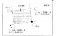
図7に、認識したマーカ座標と指定ベース角を用いて投影領域を決定した結果のイメージを示す。今、マーカ41と42のふたつのマーカ座標が認識されたとした時、図中に示したように、投影領域22は、1)マーカ41上を通過し傾きが指定ベース角であるライン、2)同じく傾きが指定ベース角の90度であるライン、3)マーカ42上を通過し傾きが指定ベース角であるライン、4)同じく傾きが指定ベース角の90度であるラインの4つのラインで囲まれる矩形領域として決定する。マーカ座標は、例えば背景画像をあらかじめ撮影しておいて、それとマーカ41、42を置いた後に撮影した画像との差分画像を計算することにより認識することができる。ここで、指定ベース角はユーザによって決められる。たとえば、投影面枠に対して傾きがないように投影したいならば、投影面枠を基準に決めればよい。 FIG. 7 shows an image of the result of determining the projection area using the recognized marker coordinates and the designated base angle. Assuming now that the two marker coordinates of the
上記で得られる投影領域22は、多くの場合投影画像33と縦横比が異なっている。そのため、図8のように、この矩形領域内の投影画像の縦横比に一致する領域22‘を最終的な投影領域とする。図8では、設定前後の投影領域の重心が一致し、かつ面積が最大となるように決定している。この場合、最初に得られた投影領域22と最終的な投影領域22’の上下辺が一致する。また、重心を一致させる方法以外にも、左辺と上辺を一致させる等の方法でもよい。 The
ここで、マーカ認識は、あらかじめ投影面色に無い色2色をそれぞれ異なるマーカの色として決めておき、あらかじめマーカと置く前の置いた後の画像から、2つのマーカの撮影色を登録しておく。登録色は、RGBまたはHSV表色系で表し、それぞれの値に上下限値を与えることにより、座標認識を行なう。投影画像の投影中も、同様に撮影部13による撮影と前の座標認識結果近傍に対する色認識によるマーカ座標認識を繰り返し行なえば、マーカ座標に追従して投影領域を変化させることも可能である。また、マーカとしては、実物を置くほかにも、例えば異なる色のレーザー光を二本投影面上に投影し、それらが映った場所をマーカとみなしてもよい。 Here, in marker recognition, two colors that are not included in the projection plane color are determined in advance as different marker colors, and the shooting colors of the two markers are registered in advance from the image that has been placed before placing the marker. . The registered color is expressed in RGB or HSV color system, and coordinate recognition is performed by giving upper and lower limit values to each value. Similarly, during the projection of the projected image, if the marker coordinate recognition by the color recognition for the vicinity of the previous coordinate recognition result is repeatedly performed by the photographing
画像変換部16では、この投影領域22上に投影画像33を一旦仮想的に置き、それを座標単位で微小領域に分割し、それらに上記で求めた投影画像−投影面間ホモグラフィの逆行列 In the
異なる投影画像を同じ投影面上の同じ投影領域上に投影させたい場合には、 If you want to project different projection images on the same projection area on the same projection surface,
また、PCで一般的に使われている3次元グラフィックボードのテクスチャマップ機能を利用すれば、投影画像4隅の点の変換をベースとして投影画像前面を一括してリアルタイムに変換し、表示させることも可能である。 In addition, if the texture map function of a 3D graphic board generally used on a PC is used, the front of the projected image is converted in real time and displayed based on the conversion of the four corners of the projected image. Is also possible.
さらに、マーカ座標の繰り返し認識と上記のリアルタイムでの画像変換とを組合わせれば、ユーザが動かすマーカ位置に合わせて投影領域を変化させながら、動画像もリアルタイムで変換し、表示することも可能である。 Furthermore, by combining the recognition of marker coordinates repeatedly and the above-mentioned real-time image conversion, it is also possible to convert and display a moving image in real time while changing the projection area according to the marker position moved by the user. is there.
[第2の実施形態]
図9は本発明の第2の実施形態による情報投影表示装置の構成を示す図、図10は本実施形態における処理フロー、およびデータの入出力関係を表す図である。[Second Embodiment]
FIG. 9 is a diagram showing a configuration of an information projection display device according to the second embodiment of the present invention, and FIG. 10 is a diagram showing a processing flow and data input / output relationship in the present embodiment.
本実施形態は、傾斜角測定部18を備えたことが第1の実施形態とは異なっており、投影領域の計算時に、傾斜角測定部18で測定した角度を指定ベース角として投影領域を計算する。本実施形態では、指定ベース角は、加速度センサーを用いて、地面(の水平面)に対して傾きがないように、地面を基準に定める。傾斜角測定には、例えばアナログ・デバイセズ社( http://www.analog.com/jp/index.html)の2軸加速度センサーADXL203を用いることが可能である。他の処理は第1の実施形態と同じでよい。 The present embodiment is different from the first embodiment in that an inclination
なお、なお、情報投影表示装置の機能は、その機能を実現するためのプログラムを、コンピュータ読み取り可能な記録媒体に記録して、この記録媒体に記録されたプログラムをコンピュータに読み込ませ、実行するものであってもよい。コンピュータ読み取り可能な記録媒体とは、フレキシブルディスク、光磁気ディスク、CD−ROM等の記録媒体、コンピュータシステムに内蔵されるハードディスク装置等の記憶装置を指す。さらに、コンピュータ読み取り可能な記録媒体は、インターネットを介してプログラムを送信する場合のように、短時間、動的にプログラムを保持するもの(伝送媒体もしくは伝送波)、その場合のサーバとなるコンピュータ内の揮発性メモリのように、一定時間プログラムを保持しているものを含む。 The function of the information projection display device is to execute a program for realizing the function by recording the program on a computer-readable recording medium and causing the computer to read the program recorded on the recording medium. It may be. The computer-readable recording medium refers to a recording medium such as a flexible disk, a magneto-optical disk, and a CD-ROM, and a storage device such as a hard disk device built in a computer system. Further, the computer-readable recording medium is a medium that dynamically holds the program for a short time (transmission medium or transmission wave) as in the case of transmitting the program via the Internet, and in the computer serving as a server in that case Such as a volatile memory that holds a program for a certain period of time.
11 投影パターン生成部
12 プロジェクション部
13 投影部
14 ホモグラフィ算出部
15 投影領域決定部
16 画像変換部
17 画像・データ記憶部
18 傾斜角測定部
21 投影面
22,22’ 投影領域
101〜110 ステップ
31 格子状投影パターン
32 撮影画像
33 投影画像
41,42 マーカDESCRIPTION OF
Claims (5)
Translated fromJapanese大きさ、形状が既知のパターンを投影パターン画像として生成する投影パターン生成部と、
画像変換部において生成された投影画像と、前記投影パターン生成部で生成された投影パターン画像を投影面上に投影するプロジェクション部と、
前記プロジェクション部に対して固定の位置関係にあり、前記投影面上に投影表示された結果の像を撮影する撮影部と、
前記撮影部で撮影された画像から、前記投影画像と前記投影面の間のホモグラフィ計算を行なうホモグラフィ算出部と、
前記投影面上におかれたマーカの位置を、前記撮影部で撮影された画像上で認識し、それに合わせて情報を投影表示する投影領域を決定する投影領域決定部と、
前記投影領域決定部で決定された投影領域上に投影表示されるように、前記ホモグラフィ算出部にて算出した結果を用いて、投影画像を変換する前記画像変換部と
を有する情報投影表示装置。An information projection display device that projects and displays information on a flat projection surface,
A projection pattern generation unit that generates a pattern having a known size and shape as a projection pattern image;
A projection image generated in the image conversion unit, a projection unit that projects the projection pattern image generated in the projection pattern generation unit onto a projection plane,
An imaging unit that is in a fixed positional relationship with respect to the projection unit and that captures an image of a result projected and displayed on the projection plane;
A homography calculation unit for performing a homography calculation between the projection image and the projection plane, from an image captured by the imaging unit;
A projection area determination unit that recognizes a position of the marker placed on the projection plane on an image captured by the imaging unit, and determines a projection area for projecting and displaying information according to the position;
An information projection display device comprising: the image conversion unit that converts a projection image using a result calculated by the homography calculation unit so as to be projected and displayed on the projection region determined by the projection region determination unit .
Priority Applications (1)
| Application Number | Priority Date | Filing Date | Title |
|---|---|---|---|
| JP2005214827AJP2007036482A (en) | 2005-07-25 | 2005-07-25 | Information projection display device and program |
Applications Claiming Priority (1)
| Application Number | Priority Date | Filing Date | Title |
|---|---|---|---|
| JP2005214827AJP2007036482A (en) | 2005-07-25 | 2005-07-25 | Information projection display device and program |
Publications (1)
| Publication Number | Publication Date |
|---|---|
| JP2007036482Atrue JP2007036482A (en) | 2007-02-08 |
Family
ID=37795219
Family Applications (1)
| Application Number | Title | Priority Date | Filing Date |
|---|---|---|---|
| JP2005214827APendingJP2007036482A (en) | 2005-07-25 | 2005-07-25 | Information projection display device and program |
Country Status (1)
| Country | Link |
|---|---|
| JP (1) | JP2007036482A (en) |
Cited By (20)
| Publication number | Priority date | Publication date | Assignee | Title |
|---|---|---|---|---|
| JP2009206800A (en)* | 2008-02-27 | 2009-09-10 | Seiko Epson Corp | Image processing apparatus, projector and image processing method |
| JP2010050540A (en)* | 2008-08-19 | 2010-03-04 | Seiko Epson Corp | Projection display apparatus, and display method |
| JP2010050542A (en)* | 2008-08-19 | 2010-03-04 | Seiko Epson Corp | Projection display apparatus, and display method |
| JP2010066406A (en)* | 2008-09-09 | 2010-03-25 | Sony Corp | Image position recognizing device, image position recognizing method, program, and compensation data setting device of image display device |
| JP2010109659A (en)* | 2008-10-30 | 2010-05-13 | Seiko Epson Corp | Measurement method of position or tilt of projection surface against projection optical system, correction method of projection image using the measurement method, and projector for performing the correction method |
| JP2010134215A (en)* | 2008-12-05 | 2010-06-17 | Seiko Epson Corp | Projector, program, and information storage medium |
| JP2010166360A (en)* | 2009-01-16 | 2010-07-29 | Seiko Epson Corp | Projector, control method thereof, and control program thereof |
| JP2010230925A (en)* | 2009-03-26 | 2010-10-14 | Tamura Seisakusho Co Ltd | Projection system, projection method, projection program, and projection vector operation device |
| JP2011147125A (en)* | 2010-01-15 | 2011-07-28 | Seiko Epson Corp | Method of calibrating projector system, program, computer system, and projector system |
| JP2011155412A (en)* | 2010-01-26 | 2011-08-11 | Panasonic Electric Works Co Ltd | Projection system and distortion correction method in the same |
| WO2015022999A1 (en)* | 2013-08-13 | 2015-02-19 | Ricoh Company, Limited | Image processing apparatus, image processing system, image processing method, and computer program |
| WO2015098187A1 (en)* | 2013-12-27 | 2015-07-02 | ソニー株式会社 | Control device, control method, and computer program |
| CN104796678A (en)* | 2015-04-28 | 2015-07-22 | 联想(北京)有限公司 | Information processing method and electronic device |
| JP2015220661A (en)* | 2014-05-20 | 2015-12-07 | 株式会社リコー | Projection system, information processor, information processing method, and program |
| US9762872B2 (en) | 2015-10-08 | 2017-09-12 | Fujitsu Limited | Apparatus, method and non-transitory computer-readable storage medium |
| WO2018173739A1 (en)* | 2017-03-23 | 2018-09-27 | セイコーエプソン株式会社 | Projector and method for controlling projector |
| JP2018170667A (en)* | 2017-03-30 | 2018-11-01 | 日本電気株式会社 | Image processing apparatus, projector device, image reading device, image processing method, and program |
| JP2020005095A (en)* | 2018-06-27 | 2020-01-09 | セイコーエプソン株式会社 | Projector and projector control method |
| WO2020044950A1 (en)* | 2018-08-30 | 2020-03-05 | ソニー株式会社 | Information processing device, information processing method, and program |
| CN115225871A (en)* | 2021-04-19 | 2022-10-21 | 成都极米科技股份有限公司 | Packaging format test method and device, projection equipment and medium |
Citations (8)
| Publication number | Priority date | Publication date | Assignee | Title |
|---|---|---|---|---|
| JPH10155077A (en)* | 1996-11-21 | 1998-06-09 | Ricoh Co Ltd | Digital image forming equipment |
| JPH10333088A (en)* | 1997-05-28 | 1998-12-18 | Canon Inc | Projection image display method and projection image display device |
| JP2003324669A (en)* | 2002-05-01 | 2003-11-14 | Canon Inc | Projection type projector tilt correction system |
| JP2004072553A (en)* | 2002-08-08 | 2004-03-04 | Digital Zuu:Kk | Image distortion correction method, and program for the same |
| JP2004274283A (en)* | 2003-03-07 | 2004-09-30 | Casio Comput Co Ltd | Projection system, projection device, image supply device, and program |
| JP2005500751A (en)* | 2001-08-15 | 2005-01-06 | 三菱電機株式会社 | Method and system for correcting keystone in a projector in any orientation with respect to the display surface |
| JP2005038388A (en)* | 2003-07-02 | 2005-02-10 | Seiko Epson Corp | Image processing system, projector, program, information storage medium, and image processing method |
| JP2005086648A (en)* | 2003-09-10 | 2005-03-31 | Nec Viewtechnology Ltd | Projection type display device |
- 2005
- 2005-07-25JPJP2005214827Apatent/JP2007036482A/enactivePending
Patent Citations (8)
| Publication number | Priority date | Publication date | Assignee | Title |
|---|---|---|---|---|
| JPH10155077A (en)* | 1996-11-21 | 1998-06-09 | Ricoh Co Ltd | Digital image forming equipment |
| JPH10333088A (en)* | 1997-05-28 | 1998-12-18 | Canon Inc | Projection image display method and projection image display device |
| JP2005500751A (en)* | 2001-08-15 | 2005-01-06 | 三菱電機株式会社 | Method and system for correcting keystone in a projector in any orientation with respect to the display surface |
| JP2003324669A (en)* | 2002-05-01 | 2003-11-14 | Canon Inc | Projection type projector tilt correction system |
| JP2004072553A (en)* | 2002-08-08 | 2004-03-04 | Digital Zuu:Kk | Image distortion correction method, and program for the same |
| JP2004274283A (en)* | 2003-03-07 | 2004-09-30 | Casio Comput Co Ltd | Projection system, projection device, image supply device, and program |
| JP2005038388A (en)* | 2003-07-02 | 2005-02-10 | Seiko Epson Corp | Image processing system, projector, program, information storage medium, and image processing method |
| JP2005086648A (en)* | 2003-09-10 | 2005-03-31 | Nec Viewtechnology Ltd | Projection type display device |
Cited By (30)
| Publication number | Priority date | Publication date | Assignee | Title |
|---|---|---|---|---|
| JP2009206800A (en)* | 2008-02-27 | 2009-09-10 | Seiko Epson Corp | Image processing apparatus, projector and image processing method |
| JP2010050540A (en)* | 2008-08-19 | 2010-03-04 | Seiko Epson Corp | Projection display apparatus, and display method |
| JP2010050542A (en)* | 2008-08-19 | 2010-03-04 | Seiko Epson Corp | Projection display apparatus, and display method |
| JP2010066406A (en)* | 2008-09-09 | 2010-03-25 | Sony Corp | Image position recognizing device, image position recognizing method, program, and compensation data setting device of image display device |
| JP2010109659A (en)* | 2008-10-30 | 2010-05-13 | Seiko Epson Corp | Measurement method of position or tilt of projection surface against projection optical system, correction method of projection image using the measurement method, and projector for performing the correction method |
| JP2010134215A (en)* | 2008-12-05 | 2010-06-17 | Seiko Epson Corp | Projector, program, and information storage medium |
| JP2010166360A (en)* | 2009-01-16 | 2010-07-29 | Seiko Epson Corp | Projector, control method thereof, and control program thereof |
| JP2010230925A (en)* | 2009-03-26 | 2010-10-14 | Tamura Seisakusho Co Ltd | Projection system, projection method, projection program, and projection vector operation device |
| JP2011147125A (en)* | 2010-01-15 | 2011-07-28 | Seiko Epson Corp | Method of calibrating projector system, program, computer system, and projector system |
| JP2011155412A (en)* | 2010-01-26 | 2011-08-11 | Panasonic Electric Works Co Ltd | Projection system and distortion correction method in the same |
| WO2015022999A1 (en)* | 2013-08-13 | 2015-02-19 | Ricoh Company, Limited | Image processing apparatus, image processing system, image processing method, and computer program |
| JP2015057876A (en)* | 2013-08-13 | 2015-03-26 | 株式会社リコー | Image processor, image processing system, image processing method, and program |
| US9787960B2 (en) | 2013-08-13 | 2017-10-10 | Ricoh Company, Limited | Image processing apparatus, image processing system, image processing method, and computer program |
| WO2015098187A1 (en)* | 2013-12-27 | 2015-07-02 | ソニー株式会社 | Control device, control method, and computer program |
| US11146771B2 (en) | 2013-12-27 | 2021-10-12 | Sony Corporation | Display control device, display control method, and program |
| JPWO2015098187A1 (en)* | 2013-12-27 | 2017-03-23 | ソニー株式会社 | Control device, control method, and computer program |
| JP2015220661A (en)* | 2014-05-20 | 2015-12-07 | 株式会社リコー | Projection system, information processor, information processing method, and program |
| CN104796678A (en)* | 2015-04-28 | 2015-07-22 | 联想(北京)有限公司 | Information processing method and electronic device |
| US9762872B2 (en) | 2015-10-08 | 2017-09-12 | Fujitsu Limited | Apparatus, method and non-transitory computer-readable storage medium |
| US11131911B2 (en) | 2017-03-23 | 2021-09-28 | Seiko Epson Corporation | Projector and method for controlling projector |
| WO2018173739A1 (en)* | 2017-03-23 | 2018-09-27 | セイコーエプソン株式会社 | Projector and method for controlling projector |
| JP2018160803A (en)* | 2017-03-23 | 2018-10-11 | セイコーエプソン株式会社 | Projector and projector control method |
| CN110463191A (en)* | 2017-03-23 | 2019-11-15 | 精工爱普生株式会社 | The control method of projector and projector |
| CN110463191B (en)* | 2017-03-23 | 2022-01-11 | 精工爱普生株式会社 | Projector and control method of projector |
| JP2018170667A (en)* | 2017-03-30 | 2018-11-01 | 日本電気株式会社 | Image processing apparatus, projector device, image reading device, image processing method, and program |
| JP2020005095A (en)* | 2018-06-27 | 2020-01-09 | セイコーエプソン株式会社 | Projector and projector control method |
| WO2020044950A1 (en)* | 2018-08-30 | 2020-03-05 | ソニー株式会社 | Information processing device, information processing method, and program |
| US11689702B2 (en) | 2018-08-30 | 2023-06-27 | Sony Corporation | Information processing apparatus and information processing method |
| CN115225871A (en)* | 2021-04-19 | 2022-10-21 | 成都极米科技股份有限公司 | Packaging format test method and device, projection equipment and medium |
| CN115225871B (en)* | 2021-04-19 | 2023-05-19 | 成都极米科技股份有限公司 | Package format test method and device, projection equipment and medium |
Similar Documents
| Publication | Publication Date | Title |
|---|---|---|
| JP7632518B2 (en) | Image processing device, image processing method, and program | |
| JP2007036482A (en) | Information projection display device and program | |
| CN110336987B (en) | Projector distortion correction method and device and projector | |
| CN110191326B (en) | Projection system resolution expansion method and device and projection system | |
| CN103765870B (en) | Image processing apparatus, projector and projector system including image processing apparatus, image processing method | |
| US6520647B2 (en) | Automatic keystone correction for projectors with arbitrary orientation | |
| JP5257616B2 (en) | Projector, program, information storage medium, and trapezoidal distortion correction method | |
| JP2020187358A (en) | Projection system, projection apparatus and calibrating method for displayed image thereof | |
| CN105308503A (en) | System and method for calibrating a display system using a short-range camera | |
| JPWO2018235163A1 (en) | Calibration apparatus, calibration chart, chart pattern generation apparatus, and calibration method | |
| US20130215132A1 (en) | System for reproducing virtual objects | |
| CN113465573A (en) | Monocular distance measuring method and device and intelligent device | |
| CN112734860B (en) | Arc-screen prior information-based pixel-by-pixel mapping projection geometric correction method | |
| CN110784691A (en) | Projection device, projection system and image correction method | |
| JP2010287074A (en) | Camera calibration apparatus, camera calibration method, camera calibration program, and recording medium recording the program | |
| JP3690581B2 (en) | POSITION DETECTION DEVICE AND METHOD THEREFOR, PLAIN POSITION DETECTION DEVICE AND METHOD THEREOF | |
| Sajadi et al. | Markerless view-independent registration of multiple distorted projectors on extruded surfaces using an uncalibrated camera | |
| JP6990694B2 (en) | Projector, data creation method for mapping, program and projection mapping system | |
| JP2004228824A (en) | Stack projection device and adjustment method thereof | |
| JP2011155412A (en) | Projection system and distortion correction method in the same | |
| JP2005140547A (en) | 3-dimensional measuring method, 3-dimensional measuring device and computer program | |
| JP5561503B2 (en) | Projector, program, information storage medium, and trapezoidal distortion correction method | |
| EP3606061B1 (en) | Projection device, projection system and an image calibration method | |
| Portalés et al. | An efficient projector calibration method for projecting virtual reality on cylindrical surfaces | |
| JP2004212142A (en) | Method of measuring dimension of image |
Legal Events
| Date | Code | Title | Description |
|---|---|---|---|
| RD04 | Notification of resignation of power of attorney | Free format text:JAPANESE INTERMEDIATE CODE: A7424 Effective date:20061130 | |
| A621 | Written request for application examination | Free format text:JAPANESE INTERMEDIATE CODE: A621 Effective date:20070815 | |
| A977 | Report on retrieval | Free format text:JAPANESE INTERMEDIATE CODE: A971007 Effective date:20100414 | |
| A131 | Notification of reasons for refusal | Free format text:JAPANESE INTERMEDIATE CODE: A131 Effective date:20100426 | |
| A521 | Written amendment | Free format text:JAPANESE INTERMEDIATE CODE: A523 Effective date:20100624 | |
| A131 | Notification of reasons for refusal | Free format text:JAPANESE INTERMEDIATE CODE: A131 Effective date:20100825 | |
| A02 | Decision of refusal | Free format text:JAPANESE INTERMEDIATE CODE: A02 Effective date:20110104 |