JP2007035582A - Flow control apparatus and fuel cell system - Google Patents
Flow control apparatus and fuel cell systemDownload PDFInfo
- Publication number
- JP2007035582A JP2007035582AJP2005221166AJP2005221166AJP2007035582AJP 2007035582 AJP2007035582 AJP 2007035582AJP 2005221166 AJP2005221166 AJP 2005221166AJP 2005221166 AJP2005221166 AJP 2005221166AJP 2007035582 AJP2007035582 AJP 2007035582A
- Authority
- JP
- Japan
- Prior art keywords
- fuel
- pressure
- valve
- chamber
- air
- Prior art date
- Legal status (The legal status is an assumption and is not a legal conclusion. Google has not performed a legal analysis and makes no representation as to the accuracy of the status listed.)
- Pending
Links
- 239000000446fuelSubstances0.000titleclaimsabstractdescription153
- 238000001514detection methodMethods0.000claimsabstractdescription96
- 238000004891communicationMethods0.000claimsdescription30
- 239000010763heavy fuel oilSubstances0.000claimsdescription4
- 238000005192partitionMethods0.000claimsdescription4
- 230000005611electricityEffects0.000claimsdescription3
- 238000007599dischargingMethods0.000abstractdescription2
- 238000010248power generationMethods0.000description29
- 230000007423decreaseEffects0.000description8
- 230000005284excitationEffects0.000description7
- 230000002093peripheral effectEffects0.000description7
- 238000002407reformingMethods0.000description4
- UFHFLCQGNIYNRP-UHFFFAOYSA-NHydrogenChemical compound[H][H]UFHFLCQGNIYNRP-UHFFFAOYSA-N0.000description3
- 230000004907fluxEffects0.000description3
- 239000001257hydrogenSubstances0.000description3
- 229910052739hydrogenInorganic materials0.000description3
- 230000003014reinforcing effectEffects0.000description3
- QVGXLLKOCUKJST-UHFFFAOYSA-Natomic oxygenChemical compound[O]QVGXLLKOCUKJST-UHFFFAOYSA-N0.000description2
- 230000003247decreasing effectEffects0.000description2
- 238000006073displacement reactionMethods0.000description2
- 239000007789gasSubstances0.000description2
- 239000000463materialSubstances0.000description2
- 238000000034methodMethods0.000description2
- 239000001301oxygenSubstances0.000description2
- 229910052760oxygenInorganic materials0.000description2
- 239000007787solidSubstances0.000description2
- 239000010409thin filmSubstances0.000description2
- 238000011144upstream manufacturingMethods0.000description2
- 238000010586diagramMethods0.000description1
- 230000005281excited stateEffects0.000description1
- 238000007429general methodMethods0.000description1
- 239000003350keroseneSubstances0.000description1
- 238000012986modificationMethods0.000description1
- 230000004048modificationEffects0.000description1
- 230000035515penetrationEffects0.000description1
- 229920000642polymerPolymers0.000description1
- 230000000630rising effectEffects0.000description1
- 238000007789sealingMethods0.000description1
Images


Classifications
- Y—GENERAL TAGGING OF NEW TECHNOLOGICAL DEVELOPMENTS; GENERAL TAGGING OF CROSS-SECTIONAL TECHNOLOGIES SPANNING OVER SEVERAL SECTIONS OF THE IPC; TECHNICAL SUBJECTS COVERED BY FORMER USPC CROSS-REFERENCE ART COLLECTIONS [XRACs] AND DIGESTS
- Y02—TECHNOLOGIES OR APPLICATIONS FOR MITIGATION OR ADAPTATION AGAINST CLIMATE CHANGE
- Y02E—REDUCTION OF GREENHOUSE GAS [GHG] EMISSIONS, RELATED TO ENERGY GENERATION, TRANSMISSION OR DISTRIBUTION
- Y02E60/00—Enabling technologies; Technologies with a potential or indirect contribution to GHG emissions mitigation
- Y02E60/30—Hydrogen technology
- Y02E60/50—Fuel cells
Landscapes
- Fuel Cell (AREA)
- Magnetically Actuated Valves (AREA)
Abstract
Description
Translated fromJapanese本発明は、流量制御装置および燃料電池システムに関する。 The present invention relates to a flow control device and a fuel cell system.
燃料電池システムは、燃料に含まれる水素と空気中の酸素とを用いて一定の割合で反応させることにより発電を行うようになっている。そのため、発電量に応じて必要とされる燃料側と空気側の供給量を計算し、それぞれの流量を制御しながら供給を行う必要がある。流量制御バルブを用いて発電を行う一般的な方法としては、下記特許文献1に記載のものが知られている。
しかしながら、このものは燃料側の供給量と空気側の供給量とを個別に制御して発電量を制御するため、電気的な制御を行う部品が多く、制御に要する電力消費が無視できない程であった。こうした制御用電力は最大能力運転時であろうと通常運転時であろうと同一消費電力であるため、例えば、最大発電能力が1kW級の家庭用コージェネレーションシステムでは制御用電力として約0.03kWを必要としており、最大能力運転時(発電量1kW)には発電量の約3%に相当するに過ぎないが、定常運転時(発電量約0.3kW)には発電量の約10%に相当し、発電効率(全発電量に対する使用可能な発電量の割合)の低下が問題となっていた。 However, in this case, since the amount of power generation is controlled by individually controlling the supply amount on the fuel side and the supply amount on the air side, there are many parts that perform electrical control, and the power consumption required for control cannot be ignored. there were. Since such control power is the same power consumption during maximum capacity operation and normal operation, for example, a household cogeneration system with a maximum power generation capacity of 1 kW requires approximately 0.03 kW as control power. It corresponds to only about 3% of the power generation amount during the maximum capacity operation (power generation amount of 1 kW), but corresponds to about 10% of the power generation amount during the steady operation (power generation amount of about 0.3 kW). However, a decrease in power generation efficiency (ratio of usable power generation amount to total power generation amount) has been a problem.
本発明は上記のような事情に基づいて完成されたものであって、制御用電力を低下させることを目的とする。 The present invention has been completed based on the above-described circumstances, and an object thereof is to reduce control power.
上記の目的を達成するための手段として、請求項1の発明は、燃料と空気とを用いてセル積層体で発電を行う燃料電池システム中に組み込まれ、前記燃料の供給路途上に配される流量制御装置であって、ケーシングと、このケーシング内において燃料流入側と前記セル積層体へ通じる燃料流出側との間に開口する供給用ポートと、この供給用ポートを開閉する弁体と、前記ケーシング内に設けられた圧力検知室と、この圧力検知室と前記燃料流出側との間を仕切り、圧力検知室と燃料流出側との圧力差に基づいて前記弁体の開閉動作を行わせる第1差圧作動部材とを備え、かつ前記圧力検知室内の圧力は前記空気の供給圧によって制御されている構成としたところに特徴を有する。 As a means for achieving the above object, the invention of
請求項2の発明は、請求項1に記載のものにおいて、前記圧力検知室は前記燃料流入側と前記燃料流出側とに対して第1および第2の連通路を介して接続され、かつ両連通路のうち前記圧力検知室と前記燃料流出側とを連通させる第2の連通路の途中には圧力検知装置が介在されるとともに、この圧力検知装置の内部には供給圧の制御された前記空気を導入するエア導入室と、前記第1および第2の連通路へ連通する燃料排出室と、両室を区画しかつ両室間に生じた差圧の大きさに基づいた撓み変位を行うとともに、前記第1差圧作動部材よりも小径に形成された第2差圧作動部材と、この第2差圧作動部材に連動し、前記燃料排出室内において前記第2の連通路へ通じる制御用ポートと、前記第2差圧作動部材に設けられて前記制御用ポートに対する開放量を制御可能な差圧作動弁とを設けたところに特徴を有する。 According to a second aspect of the present invention, in the first aspect, the pressure detection chamber is connected to the fuel inflow side and the fuel outflow side via the first and second communication paths, and both A pressure detection device is interposed in the middle of the second communication passage that communicates the pressure detection chamber and the fuel outflow side in the communication passage, and the supply pressure is controlled in the pressure detection device. An air introduction chamber for introducing air, a fuel discharge chamber communicating with the first and second communication passages, and a deflection displacement based on the magnitude of the differential pressure generated between the two chambers. And a second differential pressure actuating member having a smaller diameter than the first differential pressure actuating member, and a control unit that is linked to the second differential pressure actuating member and communicates with the second communication passage in the fuel discharge chamber. And the control port provided on the second differential pressure actuating member. Characterized in the opening amount was provided with controllable differential pressure actuated valve against.
請求項3の発明は、請求項2に記載のものにおいて、前記第1の連通路の途中には切替弁が配され、この切替弁には前記燃料流出側にバイパス接続された排出路が設けられ、前記燃料電池システムのON、OFFにより前記第1の連通路と前記排出路との切替が可能とされ、前記切替弁は、前記燃料電池システムの作動時には、前記第1の連通路を開放するとともに前記排出路を閉塞し、前記燃料電池システムの停止時には、前記第1の連通路を閉塞するとともに前記排出路を開放し、前記圧力検知室内の残留燃料を前記燃料流出側に排出するところに特徴を有する。 According to a third aspect of the present invention, in the first aspect of the present invention, a switching valve is disposed in the middle of the first communication path, and the switching valve is provided with a discharge path bypassed to the fuel outflow side. The fuel cell system can be switched between ON and OFF to switch between the first communication path and the discharge path, and the switching valve opens the first communication path when the fuel cell system is in operation. And closing the discharge passage, and closing the first communication passage and opening the discharge passage when the fuel cell system is stopped, and discharging the residual fuel in the pressure detection chamber to the fuel outflow side. It has the characteristics.
請求項4の発明は、燃料と空気とを用いてセル積層体で発電を行い、前記セル積層体に対し前記燃料を供給する燃料の供給路と前記空気を供給する空気の給気路とが設けられ、前記燃料の供給路には、前記燃料の供給路を開閉可能な遮断弁と、流量制御装置と、改質器とが配され、前記空気の給気路には、前記空気の供給圧を制御する空気圧制御装置が配された燃料電池システムであって、前記流量制御装置は、ケーシングと、このケーシング内において燃料流入側と前記セル積層体へ通じる燃料流出側との間に開口する供給用ポートと、この供給用ポートを開閉する弁体と、前記ケーシング内に設けられた圧力検知室と、この圧力検知室と前記燃料流出側との間を仕切り、圧力検知室と燃料流出側との圧力差に基づいて前記弁体の開閉動作を行わせる第1差圧作動部材とを備え、かつ前記圧力検知室内の圧力は前記空気の供給圧によって制御されているところに特徴を有する。 According to a fourth aspect of the present invention, there is provided a fuel supply path for supplying the fuel to the cell stack and an air supply path for supplying the air. A shutoff valve capable of opening and closing the fuel supply path, a flow rate control device, and a reformer are disposed in the fuel supply path, and the air supply path includes the air supply path. A fuel cell system in which an air pressure control device for controlling pressure is arranged, and the flow rate control device opens between a casing and a fuel inflow side in the casing and a fuel outflow side communicating with the cell stack. A supply port, a valve body for opening and closing the supply port, a pressure detection chamber provided in the casing, and a partition between the pressure detection chamber and the fuel outflow side, and the pressure detection chamber and the fuel outflow side The valve body opens and closes based on the pressure difference between And a first differential pressure actuating member to perform, and the pressure of the pressure sensing chamber having a characterized in that is controlled by the supply pressure of the air.
請求項5の発明は、請求項4に記載のものにおいて、前記空気の給気路および/または前記燃料の供給路には、前記燃料と前記空気の流量を調整可能な校正用の絞り弁が配されているところに特徴を有する。 According to a fifth aspect of the present invention, there is provided a calibration throttle valve capable of adjusting flow rates of the fuel and the air in the air supply path and / or the fuel supply path. It is characterized by where it is placed.
請求項6の発明は、請求項4または請求項5に記載のものにおいて、前記遮断弁にはヨークが設けられ、そのヨークの一部が前記切替弁の可動軸にまで実質的に延出されることにより、この延出部分と前記可動軸とにより前記遮断弁部分で構成される磁気回路に対して並列の磁気回路が構成されるところに特徴を有する。 According to a sixth aspect of the present invention, the shut-off valve is provided with a yoke, and a part of the yoke is substantially extended to the movable shaft of the switching valve. Thus, the extension portion and the movable shaft are characterized in that a magnetic circuit parallel to the magnetic circuit constituted by the shut-off valve portion is configured.
<請求項1または請求項4の発明>
請求項1によれば、空気の供給圧を利用して圧力検知室内の燃料圧力を調整するようにしたから、燃料側の供給量を自動制御することが可能である。さらに、燃料の供給路側に高価な流量制御弁や流量センサ等が不要となるから、大幅なコスト低減ができるだけでなく、これらによって消費される制御用電力をゼロにし、もって燃料使用量を低減し、発電効率を高めることができる。<Invention of
According to the first aspect, since the fuel pressure in the pressure detection chamber is adjusted using the supply pressure of air, the supply amount on the fuel side can be automatically controlled. Furthermore, since an expensive flow control valve, flow sensor, etc. are not required on the fuel supply path side, not only can the cost be significantly reduced, but the control power consumed by these can be reduced to zero, thereby reducing the amount of fuel used. , Power generation efficiency can be increased.
<請求項2の発明>
請求項2によれば、定常状態から、発電量を増加させる場合には、エア導入室へ導入する空気の供給圧を増加させる。すると、圧力検知装置内において燃料排出室よりエア導入室の側の圧力が高まるため、第2差圧作動部材はこのときの圧力差に応じて燃料排出室側へ変位し、これに連動して差圧作動弁が制御用ポートに対する開放量を絞る。したがって、圧力検知室内の圧力が高められ、供給用ポートの開放量が増加する。この結果、セル積層体への燃料供給量が増加し、発電量が増加する。<Invention of
According to the second aspect, when the power generation amount is increased from the steady state, the supply pressure of the air introduced into the air introduction chamber is increased. Then, since the pressure on the air introduction chamber side from the fuel discharge chamber increases in the pressure detection device, the second differential pressure actuating member is displaced to the fuel discharge chamber side according to the pressure difference at this time, and in conjunction with this, The differential pressure actuated valve reduces the amount of opening to the control port. Therefore, the pressure in the pressure detection chamber is increased, and the opening amount of the supply port is increased. As a result, the amount of fuel supplied to the cell stack increases and the amount of power generation increases.
上記により、エア導入室と燃料排出室との間に生じた圧力差が、圧力検知室と燃料排出側との圧力差として表れる。そのときに、請求項2によれば、第1差圧作動部材と第2差圧作動部材との間には受圧面積差が設定されているため、エア導入室の圧力変動が圧力検知室に対し増幅されて作用する。したがって、供給用ポートに対する弁体の動作制御を精度良く行わせ、もってセル積層体への燃料供給量に対する制御の精度を高めることができる。 Due to the above, a pressure difference generated between the air introduction chamber and the fuel discharge chamber appears as a pressure difference between the pressure detection chamber and the fuel discharge side. At that time, according to the second aspect, since the pressure receiving area difference is set between the first differential pressure actuating member and the second differential pressure actuating member, the pressure variation in the air introduction chamber is caused in the pressure detection chamber. It is amplified and acts on it. Therefore, the operation control of the valve body with respect to the supply port can be performed with high accuracy, and the control accuracy with respect to the fuel supply amount to the cell stack can be increased.
<請求項3の発明>
請求項3によれば、第1の連通路の途中に切替弁を配してある。したがって、燃料電池システムの動作開始時には、切替弁が第1の連通路を開放するため、燃料流入側と圧力検知室が連通することになり、圧力検知室内への燃料の供給がなされる。この後、圧力検知室が燃料流出側よりも高圧になると、弁体を押し上げて供給用ポートを開放し、セル積層体への燃料供給がなされる。逆に、停止時には、切替弁が第1の連通路を閉塞するとともに排出路を開放するように、流路の切替がなされる。この流路の切替によって、圧力検知室内の圧力が燃料流出側へ開放されるため、圧力検知室内の圧力は急速に低下し、その結果、弁体が急速に供給用ポートを閉じる。したがって、セル積層体に対する燃料供給を直ちに停止することができる。<Invention of
According to the third aspect, the switching valve is arranged in the middle of the first communication path. Therefore, when the operation of the fuel cell system starts, the switching valve opens the first communication path, so that the fuel inflow side and the pressure detection chamber communicate with each other, and fuel is supplied into the pressure detection chamber. Thereafter, when the pressure detection chamber becomes higher than the fuel outflow side, the valve body is pushed up to open the supply port, and fuel is supplied to the cell stack. Conversely, at the time of stoppage, the flow path is switched so that the switching valve closes the first communication path and opens the discharge path. By switching the flow path, the pressure in the pressure detection chamber is released to the fuel outflow side, so that the pressure in the pressure detection chamber rapidly decreases, and as a result, the valve body rapidly closes the supply port. Therefore, the fuel supply to the cell stack can be stopped immediately.
<請求項5の発明>
一般に、改質器あるいはセル積層体等が部品間のばらつきによって、改質器の改質能力やセル積層体の発電能力等に対し固有のばらつきを生じさせることがある。そのような場合において、請求項5によれば、校正のための絞り弁を初期調整することで、システム間のばらつきを解消することができる。<Invention of
In general, a reformer, a cell stack, or the like may cause variations inherent in the reforming capability of the reformer, the power generation capability of the cell stack, and the like due to variations among components. In such a case, according to the fifth aspect, by initially adjusting the throttle valve for calibration, it is possible to eliminate variations between systems.
<請求項6の発明>
請求項6によれば、遮断弁のコイル部を切替弁と共用したから、切替弁に専用のコイルを設ける必要がなく、部品点数の削減が可能である。<Invention of
According to the sixth aspect, since the coil portion of the shut-off valve is shared with the switching valve, it is not necessary to provide a dedicated coil for the switching valve, and the number of parts can be reduced.
<実施形態1>
本発明の実施形態1を図1ないし図9によって説明する。実施形態1における流量制御装置1は、燃料(例えば、LNG、LPG、灯油等)中に含まれる水素と空気中の酸素を図1に示すセル積層体5で反応させて発電を行う燃料電池システム中における燃料の供給路R(図1の上段側では矢印で示されたルート)の途中に配される。尚、以下の説明において、上下方向とは図1における上下方向を基準として上側を上方とし、左右方向とは図1における左右方向を基準として左側を左方とする。<
A first embodiment of the present invention will be described with reference to FIGS. The
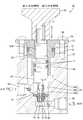
流量制御装置1は、図2に示すように、ケーシング2を有し、そのケーシング2内には入口側(図示左側)から出口側(図示右側)にかけて燃料の供給路Rが形成されている。燃料は、供給路Rの入口側に接続された燃料ポンプ(図示しない)によってケーシング2内に流入されたのち出口側から流出されると、出口側に接続された改質器9によって水素を主成分とするガスに変換され、その後セル積層体5へと送られる。ケーシング2内には、入口側から順に、遮断弁10と流量制御装置1とが設けられている。流量制御装置1は、流量調整部20と切替弁30と圧力検知装置40とから構成され、本実施形態においては、切替弁30と圧力検知装置40とは一体化されてケーシング2に組み付けられている。一方、空気の給気路Sにおいてセル積層体5の直前位置には、各燃料電池システム間のばらつきをなくす校正用の絞り弁56が設けられ、燃料電池システムの初期稼働開始時において空気の流量を調整可能となっている。 As shown in FIG. 2, the
図9は絞り弁9の断面を示しており、絞り弁9は本体ケース57を有し、本体ケース57の内部には、上室58と下室70とが形成されている。上室58は、大きさの異なる3つの円孔(大径部58A、中径部58B、小径部58C)により構成されている。中径部58Bの側面には給気路Sの上流側に連通する入口側開口59が開口している。小径部58Cの下面は下室70と連通し、下室70の側面には給気路Sの下流側に連通する出口側開口60が開口している。上室58には、同軸でニードル軸62が配されている。ニードル軸62は円筒状の支持部材63に螺合した状態で本体ケース57の上方から上室58内に嵌合されている。支持部材63の上面には周方向に沿って張り出し部67が設けられ、この張り出し部67に設けられた貫通孔68を通じて本体ケース57の上面にボルト65がねじ込まれて、支持部材63の回り止めがなされている。支持部材63の下方にはガイド筒部64が突出しており、ニードル軸62の上下方向の移動を案内している。ガイド筒部64とニードル軸62との間はニードル軸62の外周面に嵌着されたシールゴム71によってシールが図られている。尚、支持部材63と大径部58Aとの間にもシールゴム72が介在し、シールが図られている。ニードル軸62の上端には、セレーション部77が設けられ、セレーション部77には、絞り操作部材66が装着されている。また、ニードル軸62において高さ方向に関してセレーション部77とシールゴム71との間の外周面には、ねじ部82が設けられている。支持部材63の内周面においてねじ部82と対応する位置は、ねじ部63Aが刻設されており、ねじ部82と螺合可能となっている。このことによって、操作部材66の回動操作によりニードル軸62の昇降動作を行わせ、後述の絞り部76に対する絞り量の調整を行うことができる。ところで、小径部58Cには外周面にフランジ69が形成された略円筒形状の弁受け61が嵌め込まれている。弁受け61の内部には、中心軸に沿って軸孔74が形成されている。軸孔74の内周面には、径方向に4箇所、中径部58Bに開口する連通孔75が設けられ、軸孔74の途中には絞り部76が段設されている。絞り部76にはニードル軸62が突入可能とされ、ニードル軸62の突入深さによって絞り量の調整が可能となっている。 FIG. 9 shows a cross section of the
尚、本実施形態における燃料電池システムでは、改質器9とセル積層体5とが別々に設けられたPEFC(固体高分子形燃料電池)システムを例示して説明しているが、このシステム以外にも、セル積層体5による発電時における排熱を利用して改質を行う、いわゆる内部改質によって発電を行うSOFC(固体酸化物形燃料電池)システム等にも適用可能である。 In the fuel cell system according to the present embodiment, a PEFC (solid polymer fuel cell) system in which the
遮断弁10は、コイル部13への通電または非通電により燃料入口側からの燃料の流れを開放または閉止する電磁弁であり、コイル部13の中心には軸心に沿って上下動可能なプランジャ12が配されている。コイル部13の外周にはヨーク11が組み付けられ、コイル部13への励磁に伴う磁気回路の一部を構成している。プランジャ12の下端はヨーク11の下面から下方に突出し、プランジャ12の下端には弁部材16が取り付けられている。ヨーク11の下面にはシート体17が配され、その内部にはプランジャ12が突入されている。シート体17の側面にはケーシング2の燃料入口側に通じるイン側開口14が開口し、下面には次述する導入路3へ通じるアウト側開口15が形成されている。ヨーク11の下面にはその中心部に下向きに筒部が形成され、プランジャ12の昇降動作を許容しているとともに、ヨーク11の下面と弁部材16との間には戻しばね18が介在され、弁部材16に対しアウト側開口15を閉止するように作用している。すなわち、コイル部13への通電に伴う励磁によってプランジャ12は戻しばね18の付勢力に抗して上昇しアウト側開口15を開放するが、非通電によって非励磁状態になると、戻しばね18は弁部材16に対しアウト側開口15を閉じるように付勢する。 The shut-off
また、ケーシング2内において遮断弁10の下流側には流量調整部20が配され、これらの間にはアウト側開口15に通じる導入路(燃料流入側)3が形成されている。一方、ケーシング2内における流量調整部20の下流側には改質器9に通じる導出路(燃料流出側)4が形成されている。 In the
流量調整部20は上蓋21Aと下蓋21Bとによって構成された中空のケース体21を有してなる。上蓋21Aには導入路3とケース体21内を連通させる供給用ポート27と、導出路4とケース体21内を連通させる排出用ポート29とが開口している。 The flow
ケース体21内には同ケース体21内を上室22と下室(圧力検知室6)とに区画する第1ダイアフラム(第1差圧作動部材)25が組み込まれている。この第1ダイアフラム25は良好な可撓性を有するゴム材よりなる円形状の薄膜板を有し、その外周縁は弛み部分を介したうえで上蓋21Aと下蓋21Bとによって挟持されている。この弛み部分により、第1ダイアフラム25は、上下方向に変位可能となっている。第1ダイアフラム25の中心部上面には円形の第1補強板23が取り付けられている。また、第1ダイアフラム25の中心には上方に向けてシャフト26が立設されている。その上端には供給用ポート27を開閉する弁体24が固定されている。さらに、上蓋21Aにおいて供給用ポート27の下方にはガイド部材28が固定されている。このガイド部材28の中心には上下方向に延びる円筒状の案内筒が設けられており、シャフト26をスライド可能に挿通している。また、シャフト26とガイド部材28との間にはリターンスプリング39が介在されていて、弁体24に対し供給用ポート27を閉止する方向に付勢している。 A first diaphragm (first differential pressure actuating member) 25 that divides the
また、ケーシング2の外面には切替弁30と圧力検知装置40とが並設されている。これら切替弁30と圧力検知装置40のそれぞれの下部構造は共用化され、流路連絡部材50としてケーシング2内に埋め込まれている。 In addition, a switching
切替弁30は、圧力検知室6と導入路3及び導出路4とのそれぞれの連通路の切替えを行うものであり、外部電源に接続された励磁コイル37を有している。また、励磁コイル37の中心には軸心に沿って上下動可能な可動軸38が配され、励磁コイル37の通電による励磁に伴いアッパスプリング35に抗して上動し、非通電によりアッパスプリング35のばね力によって下動する。一方、可動軸38の下方であって流路連絡部材50内には切替室54が形成されている。この切替室54は導出路4に対し排出路Cを介して連通し、また、切替室54の他の面には中継室55へ通じる切替ポート33が開口している。さらに、切替室54内には支持軸31が切替ポート33を同軸で貫いた状態で収容されるとともに、この支持軸31の下端には切替ポート33を開閉可能なバルブ32が装着されている。さらにまた、支持軸31にはロアスプリング36が巻装されていて、バルブ32が切替ポート33を閉止するように付勢している。但し、励磁コイル37への通電時には可動軸38と支持軸31とは図5に示すように離間状態にあるが、非通電時にはロアスプリング36のばね力より強力なばね力に設定されたアッパスプリング35のばね力によって可動軸38の下動と共に支持軸31も押し下げられ、もって切替ポート33を開放可能としている。また、中継室55は導入路3に対し誘導路Bを介して連通しているが、上記した非通電時においてバルブ32が切替ポート33を開放したときに、これと同時に誘導路Bと中継室55とをつなぐ小孔34を閉止するようになっている。 The switching
上記した中継室55はつなぎ流路Aを介して圧力検知装置40側において圧力検知室6に通じる流路へ通じている。このつなぎ流路Aは、流路連絡部材50内に配される鉛直路Eとケーシング2内に配される制御流路Dとを介して、圧力検知室6に連通している。尚、ケース体21において制御流路Dと連通する箇所には固定オリフィス19が配されている。かくして、制御流路D、鉛直路E、つなぎ流路A及び誘導路Bによって圧力検知室6と導入路3とを接続する第1の連通路が構成されている。 The
圧力検知装置40は上部側の構造部として本体部41を備え、ここには空気の給気路Sと接続されたエア導入管(図1における圧力導入管)Fが装着されている。但し、給気路S途上においてエア導入管Fとの分岐部分より上流側にはセル積層体5及びエア導入管Fへ送られる空気圧を調整可能な昇圧装置(空気圧制御装置)7が配されている。本体部41にはその内部をエア導入室52と燃料排出室51とに区画する第2ダイアフラム(第2差圧作動部材)42が設けられている。 The
この第2ダイアフラム42は良好な可撓性を有するゴム材よりなるドーナツ形の薄膜板を有し、その外周縁は弛み部分を介したうえで、本体部41と流路連絡部材50とによって挟持されている。そして、上記した弛み部分により、第2ダイアフラム42は、上下方向に変位可能となっている。第2ダイアフラム42の中心には差圧作動弁46が第2ダイアフラム42と一体で設けられている。差圧作動弁46の上面はボス状に形成され、その下面は平面状に形成されている。この差圧作動弁46には円形のかつ所定の剛性を有する第2補強板43が上方から嵌着されている。また、差圧作動弁46の上面には調整ばね44の一端が嵌着され、他端は本体部41内の上部にねじ止めされたばね力調整部材47に当接されており、そのねじ込み量を調整することで第2ダイアフラム42を押し下げる方向の付勢力を調整可能としている。 The
流路連絡部材50において、差圧作動弁46の下面中心部と対応する位置には円筒状部48が突出され、その上端には差圧作動弁46に対する弁座が形成されている。また、円筒状部48の内部には軸心に沿って鉛直路Eが形成され、上端は制御用ポート49として開口している。さらに、鉛直路Eは前記したつなぎ流路A及び制御流路Dにそれぞれ連通している。一方、第2ダイアフラム42の下面側には調整ばね44と同芯でバランサースプリング45が配されている。この実施形態では、バランサースプリング45の方が調整ばね44のばね力よりも大きくなるように設定されている。但し、このばね力差は差圧作動弁46、第2ダイアフラム42及び第2補強板43の自重等にほぼ見合う大きさに設定されている。したがって、第2ダイアフラム42の昇降動作は専らエア導入室52と燃料排出室51との間の圧力差のみに依存することになる。また、発電量が一定となった状態(定常状態)では、エア導入室52と燃料排出室51との圧力差が調整ばね44とバランサースプリング45とのばね力の差とバランスし、このときの圧力差にほぼ比例して差圧作動弁46を制御用ポート49から所定高さだけ浮かせて所定の開放量を保持できるようにしてある。さらに、この所定の開放量に応じて、圧力検知室6内の圧力が所定の圧力に設定されるようになっている。 In the flow
上記した燃料排出室51は検知流路Gを介して導出路4へ通じており、かつ検知流路Gの導出路4寄りの位置には、可変オリフィス8が配されている。このため、定常状態では導出路4内を流れる燃料により検知流路G内の燃料が吸引され、燃料排出室51内の燃料は検知流路Gを通じて導出路4へと排出される。なお、制御流路D、鉛直路E及び検知流路Gによって圧力検知室6と導出路4とを接続する第2の連通路が構成されている。 The
本実施形態は以上のような構造であって、続いてその作用を説明する。
まずは、燃料電池システムの再稼働させる前の状態について説明する。遮断弁10については、弁部材16がアウト側開口15を閉止している。切替弁30については、バルブ32が切替ポート33を開放し、小孔34を閉止している。流量調整部20については、圧力検知室6内が減圧された状態にあるため(その理由は改めて後述する。)、弁体24が供給用ポート27を閉止している。圧力検知装置40については、差圧作動弁46が制御用ポート49を閉止している。The present embodiment has the above-described structure, and the operation thereof will be described subsequently.
First, a state before the fuel cell system is restarted will be described. For the
次に、燃料電池システムを稼働させて燃料の供給圧が一定となる定常状態に至るまでの状態について説明する。
燃料電池システムを稼働させると、遮断弁10のコイル部13への通電に伴う励磁によってプランジャ12は戻しばね18の付勢力に抗して上昇しアウト側開口15を開放する。また、切替弁30の可動軸38は励磁コイル37の通電による励磁に伴いアッパスプリング35に抗して上動する。支持軸31は可動軸38による押し下げ状態から解放され、ロアスプリング36によって押し上げられると、バルブ32が切替ポート33を閉止するとともに小孔34を開放する。Next, a state from when the fuel cell system is operated until a steady state where the fuel supply pressure becomes constant will be described.
When the fuel cell system is operated, the
上記の状態で、燃料が図示しない燃料ポンプによって入口側から供給路R内に送り込まれると、燃料は遮断弁10のイン側開口14、アウト側開口15を経由して導入路3内へ到達する。一方、空気は、昇圧装置7によって供給圧が制御された状態で、セル積層体5に向けて供給されるとともにエア導入管Fを介してエア導入室52内へと送られる。 In the above state, when the fuel is fed into the supply path R from the inlet side by a fuel pump (not shown), the fuel reaches the
稼働開始時には、弁体24が供給用ポート27を閉止した状態にあり、燃料は誘導路B、小孔34を通って切替弁30の中継室55内に送られ、その後つなぎ流路A、鉛直路E内に送られる。ここで、第2ダイアフラム弁42が制御用ポート49を閉止した状態にあるため、燃料は鉛直路Eおよび制御流路Dを通って圧力検知室6内に送られる。すると、圧力検知室6は上室22と比べて圧力が高くなるため、第1ダイアフラム25が押し上げられて、弁体24が供給用ポート27を全開にする。そのため燃料は供給用ポート27から上室22内に流入し排出用ポート29を通過して導出路4へと流れることになる。燃料は改質器9を経由してセル積層体5へと送られると共に、導出路4内で排出用ポート29から出口側に向かう燃料の流れにより検知流路G内の燃料が吸引される。したがって、第2ダイアフラム42はエア導入室52側から受ける圧力に加えて、検知流路Gを介して燃料排出室51内が減圧された状態となるから、制御用ポート49は閉止状態に保持される。これにより、つなぎ流路Aから鉛直路E内に送り込まれた燃料は、制御流路Dを通じて圧力検知室6側へ一方的に送り込まれることになるが、弁体24が供給用ポート27を全開にした状態では第1ダイアフラム25の上方への変位が規制された状態にあるため、圧力検知室6内の圧力は上昇する。このとき、つなぎ流路Aよりも先の空間(制御流路D、鉛直路E及び圧力検知室6とからなる空間)は閉じられた系となっているから、同一圧力となる。そして、この空間内の圧力(圧力検知室6内の圧力)が、制御用ポート49を閉止する差圧作動弁46にかかる圧力よりも大きくなると、差圧作動弁46が押し上げられて制御用ポート49を開放し、前記空間内の燃料が抜かれて一気に燃料排出室51へ流れ込むと同時に検知流路Gを通じて導出路4へと排出される。このとき、差圧作動弁46が一時的に大きく押し上げられて制御用ポート49は大きな開放量となるが、上記の圧抜きに伴って差圧作動弁46に対する押上力が減少して制御用ポート49の開放量が絞られ、第2ダイアフラム42が燃料排出室51とエア導入室52との圧力差に応じた開放位置で安定する(定常状態)。このようにして制御用ポート49に対する開放量が安定することに伴い、圧力検知室6内の圧力も減少した後に定常化される。 At the start of operation, the
これに伴い、第1ダイアフラム25は下降し上室22と圧力検知室6とが圧力バランスした高さ位置で停止してこの位置で供給用ポート27の開放量を安定化させる。 Accordingly, the
次に、定常状態から発電量を増加させる場合について説明する。
定常状態から発電量を増加させるには、空気の供給圧を増加させてエア導入室52内の圧力を増加させる。エア導入室52内の圧力が増加すると、圧力検知装置40内において燃料排出室51よりエア導入室52の側の圧力が高まるため、第2ダイアフラム42はこのときの圧力差に応じて燃料排出室51側へ変位し、制御用ポート49に対する開放量が絞られると、圧力検知室6内の圧力が高められて所定の圧力に増圧される。すると、圧力検知室6と上室22との圧力差によって第1ダイアフラム25が上昇するとともに弁体24が押し上げられて、供給用ポート27の開放量が増加する。供給用ポート27の開放量が増加し、上室22内の圧力が高まって圧力検知室6内の圧力と等しくなると、第1ダイアフラム25の上昇が停止し、定常状態へと移行する。こうして、セル積層体5への燃料供給量が増えると、発電量が増加する。Next, a case where the power generation amount is increased from the steady state will be described.
In order to increase the power generation amount from the steady state, the pressure in the
続いて、定常状態から発電量を減少させる場合について説明する。
定常状態から発電量を減少させるには、空気の供給圧を減少させてエア導入室52内の圧力を減少させる。すると、圧力検知装置40内において燃料排出室51よりエア導入室52の側の圧力が低くなるため、第2ダイアフラム42はこのときの圧力差に応じてエア導入室52側へ変位し、制御用ポート49に対する開放量が増加するため、圧力検知室6内の圧力が低下して所定の圧力に減圧される。すると、圧力検知室6と上室22との圧力差によって第1ダイアフラム25が降下するとともに弁体24が押し下げられて、供給用ポート27の開放量が低下する。供給用ポート27の開放量が低下し、上室22内の圧力が低下して圧力検知室6内の圧力と等しくなると、第1ダイアフラム25の降下が停止し、定常状態へと移行する。こうして、セル積層体5への燃料供給量が減ると、発電量が減少する。Then, the case where electric power generation amount is reduced from a steady state is demonstrated.
In order to reduce the power generation amount from the steady state, the pressure in the
最後に、燃料電池システムを停止させる場合について説明する。
燃料電池システムを停止させると、遮断弁10のコイル部13への非通電により非励磁状態となり、戻しばね18は弁部材16に対しアウト側開口15を閉じるように付勢する。また、切替弁30は励磁コイル37の非通電時にはロアスプリング36のばね力より強力なばね力に設定されたアッパスプリング35のばね力によって可動軸38の下動と共に支持軸31も押し下げられ、バルブ32が切替ポート33を開放し、誘導路Bと中継室55とをつなぐ小孔34を閉止する。Finally, a case where the fuel cell system is stopped will be described.
When the fuel cell system is stopped, the
上記の状態で、燃料が図示しない排出ポンプによってケーシング2の出口側から排出されると、圧力検知室6内の残留燃料は制御流路D、鉛直路E及びつなぎ流路Aを経由して切替室54内へ送られ、さらに排出路C、検知流路G及び導出路4を通じて出口側へと排出される。すると、圧力検知室6内の圧力は急速に低下し、上室22と圧力検知室6との圧力差によって第1ダイアフラム25が降下し、弁体24が供給用ポート27を急速に閉止する。これにて、導入路3内の残留燃料を全量排出するまでもなくセル積層体5に対する燃料供給を直ちに停止することができる。尚、燃料排出室51内の圧力についても急速に低下することになるため、エア導入室52と燃料排出室51との圧力差によって第2ダイアフラム42が降下し、差圧作動弁46が制御用ポート49を閉止する。一方、空気側では、昇圧装置7への非通電によってセル積層体5に対する供給が停止される。 In the above state, when the fuel is discharged from the outlet side of the
このように、本実施形態においては、エア導入室52と燃料排出室51との間の圧力差に応じて、制御用ポート49が所定の開放量に制御され、この開放量に基づいて圧力検知室6内の圧力が制御され、その結果、圧力検知室6と上室22との間の圧力差として表れ、かつ第1ダイアフラム25と第2ダイアフラム42との間には受圧面積差が設定されているため、エア導入室52の圧力変動が圧力検知室6に対し増幅されて作用する。したがって、空気の給気路Sにおける微小な圧力変動に対し、供給用ポート27に対する弁体24の動作制御を精度良く行わせ、もってセル積層体5への燃料供給量に対する制御の精度を高めることができる。 Thus, in the present embodiment, the
また、本実施形態では、空気の供給圧をエア導入室52内に直接取り込んで、差圧作動弁46に制御用ポート49を開閉するように作用させ、圧力検知室6内の燃料圧力を調整することで供給用ポート27を開閉するようにしている。したがって、少なくとも圧力検知室6に対する圧力制御を圧力検知装置40に空気を取り込むという機械的な制御によって行うこととし、切替弁30以外は電気的な制御手段を用いないから、流量制御に必要な制御用電力を大幅に低減することが可能となり、もって燃料消費量を低減し、発電効率を高めることが可能である。 In the present embodiment, the air supply pressure is directly taken into the
さらに、改質器9の改質能力やセル積層体5の発電能力等の部品間におけるばらつきについては、校正用の絞り弁56によって燃料あるいは空気の供給量を初期調整しておくことで、例えば発電量の設定を行う制御盤に表示された設定値と実際の発電量とで差異が生じないようにすることが可能である。 Furthermore, with regard to variations among components such as the reforming capacity of the
<実施形態2>
本発明の実施形態2を図10および図11によって説明する。実施形態2における流量制御装置1は、図10に示すように、実施形態1のものにおける切替弁30の励磁コイル37をなくし、遮断弁10のコイル部13を遮断弁10と切替弁30とで共用するようにしたものであり、その他重複する構造については説明を省略する。<
A second embodiment of the present invention will be described with reference to FIGS. As shown in FIG. 10, the
本実施形態においては、実施形態1で開示されたものとは、切替弁30と圧力検知装置40の配置が入れ替えられて、切替弁30が遮断弁10に隣接する位置に配されている。可動軸38の上面には、同軸でコアヨーク78が配されている。コアヨーク78と可動軸38とは、スリーブ80内に収容され、スリーブ80の下端は流路連絡部材50に固定されている。尚、コアヨーク78はスリーブ80の上端位置で固定されている。 In the present embodiment, the arrangement of the switching
遮断弁10のヨーク11のうちコイル部13の上面と対向する面から切替弁30に向けてフレームヨーク79が延出され、コアヨーク78にほぼ当接した状態とされている。遮断弁10のヨーク11のうちコイル部13の下面と対向する面から切替弁30に向けてプレートヨーク81が延出され、スリーブ80の下端部を挿通させている。 A
通電状態では、図11に示すように、コイル部13が励磁されて磁束が発生し遮断弁10側にはヨーク11を通じて磁気回路が構成される。また、切替弁30側にはプレートヨーク81、可動軸38、フレームヨーク79を通じて前記遮断弁10側に構成される磁気回路に対して並列の磁気回路が構成される。したがって、コアヨーク78と可動軸38との間には吸引力が働いて、可動軸38はアッパスプリング35のばね力に抗してコアヨーク78側に引き寄せられる。非通電状態では、コイル部13が非励磁状態となって磁束がなくなり、コアヨーク78と可動軸38との間の吸引力が働かなくなるため、可動軸38はアッパスプリング35のばね力を受けて下動する。 In the energized state, as shown in FIG. 11, the
以上のように、本実施形態では遮断弁10のコイル部13を切替弁30と共用したから、切替弁30に専用のコイルを設ける必要がなく部品点数を削減可能である。 As described above, in this embodiment, since the
<他の実施形態>
本発明は上記記述及び図面によって説明した実施形態に限定されるものではなく、例えば次のような実施形態も本発明の技術的範囲に含まれ、さらに、下記以外にも要旨を逸脱しない範囲内で種々変更して実施することができる。<Other embodiments>
The present invention is not limited to the embodiments described with reference to the above description and drawings. For example, the following embodiments are also included in the technical scope of the present invention, and further, within the scope not departing from the gist of the invention other than the following. Various modifications can be made.
(1)本実施形態においては、燃料が圧力検知室6内に流入する流路と圧力検知室6内から流出する流路とが一体となった流路(制御流路Dおよび鉛直路E)を例示したが、圧力検知室6には流入側と流出側をそれぞれ別に設けてもよい。 (1) In the present embodiment, a flow path (control flow path D and vertical path E) in which a flow path through which fuel flows into the
(2)本実施形態においては、差圧作動弁46が第2ダイアフラム42に一体に形成されたものを示したが、第1ダイアフラム25と同様に、別体構成にしてこれらを組み付けた関係にしてもよい。 (2) In the present embodiment, the differential
(3)本実施形態では、圧力検知室6に燃料を導入したが、この圧力検知室6に空気を直接導入し、制御された空気圧に基づいて供給用ポート27に対する開放量を制御するようにしてもよい。 (3) In this embodiment, the fuel is introduced into the
(4)実施形態2では、フレームヨーク79およびプレートヨーク81がヨーク11と一体で形成されているものを示したが、ヨーク11と別体で設けたものを接続する構成としてもよい。 (4) Although the
A…つなぎ流路(第1の連通路の一部を構成する流路)
B…誘導路(第1の連通路の一部を構成する流路)
C…排出路
D…制御流路(第1および第2の連通路に共用されている流路)
E…鉛直路(第1および第2の連通路に共用されている流路)
G…検知流路(第2の連通路の一部を構成する流路)
R…燃料の供給路
S…空気の給気路
1…流量制御装置
2…ケーシング
3…導入路(燃料流入側)
4…導出路(燃料流出側)
5…セル積層体
6…圧力検知室
9…改質器
10…遮断弁
11…ヨーク
24…弁体
25…第1ダイアフラム(第1差圧作動部材)
27…供給用ポート
30…切替弁
33…切替ポート
38…可動軸
40…圧力検知装置
42…第2ダイアフラム(第2差圧作動部材)
46…差圧作動弁
49…制御用ポート
51…燃料排出室
52…エア導入室
56…絞り弁A: Connecting flow path (flow path constituting a part of the first communication path)
B: Guidance path (flow path constituting a part of the first communication path)
C: Discharge path D: Control flow path (flow path shared by the first and second communication paths)
E ... Vertical path (flow path shared by the first and second communication paths)
G: Detection flow path (flow path constituting a part of the second communication path)
R ... Fuel supply path S ...
4 ... Lead-out route (fuel outflow side)
DESCRIPTION OF
27 ...
46 ... Differential
Claims (6)
Translated fromJapaneseケーシングと、このケーシング内において燃料流入側と前記セル積層体へ通じる燃料流出側との間に開口する供給用ポートと、この供給用ポートを開閉する弁体と、前記ケーシング内に設けられた圧力検知室と、この圧力検知室と前記燃料流出側との間を仕切り、圧力検知室と燃料流出側との圧力差に基づいて前記弁体の開閉動作を行わせる第1差圧作動部材とを備え、
かつ前記圧力検知室内の圧力は前記空気の供給圧によって制御されていることを特徴とする流量制御装置。A flow rate control device that is incorporated in a fuel cell system that generates power in a cell stack using fuel and air, and is disposed on the fuel supply path,
A casing, a supply port that opens between a fuel inflow side in the casing and a fuel outflow side that leads to the cell stack, a valve body that opens and closes the supply port, and a pressure provided in the casing A detection chamber, and a first differential pressure actuating member that partitions the pressure detection chamber and the fuel outflow side and opens and closes the valve body based on a pressure difference between the pressure detection chamber and the fuel outflow side. Prepared,
The pressure control device is characterized in that the pressure in the pressure detection chamber is controlled by the supply pressure of the air.
この圧力検知装置の内部には供給圧の制御された前記空気を導入するエア導入室と、前記第1および第2の連通路へ連通する燃料排出室と、両室を区画しかつ両室間に生じた差圧の大きさに基づいた撓み変位を行うとともに、前記第1差圧作動部材よりも小径に形成された第2差圧作動部材と、この第2差圧作動部材に連動し、前記燃料排出室内において前記第2の連通路へ通じる制御用ポートと、前記第2差圧作動部材に設けられて前記制御用ポートに対する開放量を制御可能な差圧作動弁とを設けたことを特徴とする請求項1記載の流量制御装置。The pressure detection chamber is connected to the fuel inflow side and the fuel outflow side via first and second communication passages, and communicates the pressure detection chamber and the fuel outflow side of both communication passages. A pressure detector is interposed in the middle of the second communication path, and
Inside the pressure detection device, an air introduction chamber for introducing the air whose supply pressure is controlled, a fuel discharge chamber communicating with the first and second communication paths, and a partition between both chambers. The second differential pressure actuating member formed with a smaller diameter than the first differential pressure actuating member, and the second differential pressure actuating member in conjunction with the second differential pressure actuating member. A control port communicating with the second communication path in the fuel discharge chamber, and a differential pressure operating valve provided in the second differential pressure operating member and capable of controlling an opening amount with respect to the control port; The flow rate control device according to claim 1, wherein
前記切替弁は、前記燃料電池システムの作動時には、前記第1の連通路を開放するとともに前記排出路を閉塞し、
前記燃料電池システムの停止時には、前記第1の連通路を閉塞するとともに前記排出路を開放し、前記圧力検知室内の残留燃料を前記燃料流出側に排出することを特徴とする請求項2記載の流量制御装置。A switching valve is arranged in the middle of the first communication path. The switching valve is provided with a discharge passage bypassed on the fuel outflow side, and the first communication path is turned on and off by the fuel cell system. Switching between the passage and the discharge path is possible,
The switching valve opens the first communication path and closes the discharge path during operation of the fuel cell system,
3. The fuel cell system according to claim 2, wherein when the fuel cell system is stopped, the first communication passage is closed and the discharge passage is opened to discharge residual fuel in the pressure detection chamber to the fuel outflow side. Flow control device.
前記セル積層体に対し前記燃料を供給する燃料の供給路と前記空気を供給する空気の給気路とが設けられ、前記燃料の供給路には、前記燃料の供給路を開閉可能な遮断弁と、流量制御装置と、改質器とが配され、前記空気の給気路には、前記空気の供給圧を制御する空気圧制御装置が配された燃料電池システムであって、
前記流量制御装置は、ケーシングと、このケーシング内において燃料流入側と前記セル積層体へ通じる燃料流出側との間に開口する供給用ポートと、この供給用ポートを開閉する弁体と、前記ケーシング内に設けられた圧力検知室と、この圧力検知室と前記燃料流出側との間を仕切り、圧力検知室と燃料流出側との圧力差に基づいて前記弁体の開閉動作を行わせる第1差圧作動部材とを備え、かつ前記圧力検知室内の圧力は前記空気の供給圧によって制御されていることを特徴とする燃料電池システム。Electricity is generated in the cell stack using fuel and air,
A fuel supply path for supplying the fuel to the cell stack and an air supply path for supplying the air are provided, and a shutoff valve capable of opening and closing the fuel supply path is provided in the fuel supply path A flow rate control device and a reformer, and a fuel cell system in which an air pressure control device for controlling a supply pressure of the air is arranged in the air supply path,
The flow control device includes a casing, a supply port that opens between a fuel inflow side and a fuel outflow side that leads to the cell stack in the casing, a valve body that opens and closes the supply port, and the casing A pressure detection chamber provided in the interior, a partition between the pressure detection chamber and the fuel outflow side, and a first opening / closing operation of the valve body based on a pressure difference between the pressure detection chamber and the fuel outflow side. A fuel cell system comprising: a differential pressure operating member; and the pressure in the pressure detection chamber is controlled by the supply pressure of the air.
Priority Applications (1)
| Application Number | Priority Date | Filing Date | Title |
|---|---|---|---|
| JP2005221166AJP2007035582A (en) | 2005-07-29 | 2005-07-29 | Flow control apparatus and fuel cell system |
Applications Claiming Priority (1)
| Application Number | Priority Date | Filing Date | Title |
|---|---|---|---|
| JP2005221166AJP2007035582A (en) | 2005-07-29 | 2005-07-29 | Flow control apparatus and fuel cell system |
Publications (1)
| Publication Number | Publication Date |
|---|---|
| JP2007035582Atrue JP2007035582A (en) | 2007-02-08 |
Family
ID=37794563
Family Applications (1)
| Application Number | Title | Priority Date | Filing Date |
|---|---|---|---|
| JP2005221166APendingJP2007035582A (en) | 2005-07-29 | 2005-07-29 | Flow control apparatus and fuel cell system |
Country Status (1)
| Country | Link |
|---|---|
| JP (1) | JP2007035582A (en) |
Cited By (16)
| Publication number | Priority date | Publication date | Assignee | Title |
|---|---|---|---|---|
| JP2015170267A (en)* | 2014-03-10 | 2015-09-28 | 旭有機材工業株式会社 | Flow regulating valve and fluid control device including the same |
| JP2020034002A (en)* | 2007-02-27 | 2020-03-05 | デカ・プロダクツ・リミテッド・パートナーシップ | Pump cassette |
| JP2021067309A (en)* | 2019-10-23 | 2021-04-30 | タイム技研株式会社 | Solenoid valve unit |
| US11529444B2 (en) | 2007-02-27 | 2022-12-20 | Deka Products Limited Partnership | Blood treatment systems and methods |
| US11633526B2 (en) | 2007-02-27 | 2023-04-25 | Deka Products Limited Partnership | Cassette system integrated apparatus |
| US11725645B2 (en) | 2006-04-14 | 2023-08-15 | Deka Products Limited Partnership | Automated control mechanisms and methods for controlling fluid flow in a hemodialysis apparatus |
| US11752248B2 (en) | 2008-01-23 | 2023-09-12 | Deka Products Limited Partnership | Medical treatment system and methods using a plurality of fluid lines |
| US11754064B2 (en) | 2006-04-14 | 2023-09-12 | Deka Products Limited Partnership | Fluid pumping systems, devices and methods |
| US11793915B2 (en) | 2007-02-27 | 2023-10-24 | Deka Products Limited Partnership | Hemodialysis systems and methods |
| US11890403B2 (en) | 2011-05-24 | 2024-02-06 | Deka Products Limited Partnership | Hemodialysis system |
| US12059516B2 (en) | 2007-02-27 | 2024-08-13 | Deka Products Limited Partnership | Blood circuit assembly for a hemodialysis system |
| US12078162B2 (en) | 2018-03-30 | 2024-09-03 | Deka Products Limited Partnership | Liquid pumping cassettes and associated pressure distribution manifold and related methods |
| US12220507B2 (en) | 2011-05-24 | 2025-02-11 | Deka Products Limited Partnership | Blood treatment systems and methods |
| US12303631B2 (en) | 2011-11-04 | 2025-05-20 | Deka Products Limited Partnership | Medical treatment system and methods using a plurality of fluid lines |
| US12311086B2 (en) | 2008-01-23 | 2025-05-27 | Deka Products Limited Partnership | Pump cassette and methods for use in medical treatment system using a plurality of fluid lines |
| US12421952B2 (en) | 2013-03-15 | 2025-09-23 | Deka Products Limited Partnership | Reciprocating diaphragm pumps for blood treatment systems and methods |
Citations (2)
| Publication number | Priority date | Publication date | Assignee | Title |
|---|---|---|---|---|
| JP2002373682A (en)* | 2001-06-15 | 2002-12-26 | Honda Motor Co Ltd | Fuel cell system |
| JP2003068334A (en)* | 2001-08-27 | 2003-03-07 | Honda Motor Co Ltd | Fuel circulation type fuel cell system |
- 2005
- 2005-07-29JPJP2005221166Apatent/JP2007035582A/enactivePending
Patent Citations (2)
| Publication number | Priority date | Publication date | Assignee | Title |
|---|---|---|---|---|
| JP2002373682A (en)* | 2001-06-15 | 2002-12-26 | Honda Motor Co Ltd | Fuel cell system |
| JP2003068334A (en)* | 2001-08-27 | 2003-03-07 | Honda Motor Co Ltd | Fuel circulation type fuel cell system |
Cited By (23)
| Publication number | Priority date | Publication date | Assignee | Title |
|---|---|---|---|---|
| US11725645B2 (en) | 2006-04-14 | 2023-08-15 | Deka Products Limited Partnership | Automated control mechanisms and methods for controlling fluid flow in a hemodialysis apparatus |
| US12044229B2 (en) | 2006-04-14 | 2024-07-23 | Deka Products Limited Partnership | Fluid pumping systems, devices and methods |
| US11828279B2 (en) | 2006-04-14 | 2023-11-28 | Deka Products Limited Partnership | System for monitoring and controlling fluid flow in a hemodialysis apparatus |
| US11754064B2 (en) | 2006-04-14 | 2023-09-12 | Deka Products Limited Partnership | Fluid pumping systems, devices and methods |
| US11793915B2 (en) | 2007-02-27 | 2023-10-24 | Deka Products Limited Partnership | Hemodialysis systems and methods |
| US12044228B2 (en) | 2007-02-27 | 2024-07-23 | Deka Products Limited Partnership | Cassette system integrated apparatus |
| US11529444B2 (en) | 2007-02-27 | 2022-12-20 | Deka Products Limited Partnership | Blood treatment systems and methods |
| US12064540B2 (en) | 2007-02-27 | 2024-08-20 | Deka Products Limited Partnership | Hemodialysis systems and methods |
| JP7163269B2 (en) | 2007-02-27 | 2022-10-31 | デカ・プロダクツ・リミテッド・パートナーシップ | membrane based valve |
| US11779691B2 (en) | 2007-02-27 | 2023-10-10 | Deka Products Limited Partnership | Pumping cassette |
| US12066017B2 (en) | 2007-02-27 | 2024-08-20 | Deka Products Limited Partnership | Pumping cassette |
| US12059516B2 (en) | 2007-02-27 | 2024-08-13 | Deka Products Limited Partnership | Blood circuit assembly for a hemodialysis system |
| JP2020034002A (en)* | 2007-02-27 | 2020-03-05 | デカ・プロダクツ・リミテッド・パートナーシップ | Pump cassette |
| US11633526B2 (en) | 2007-02-27 | 2023-04-25 | Deka Products Limited Partnership | Cassette system integrated apparatus |
| US11752248B2 (en) | 2008-01-23 | 2023-09-12 | Deka Products Limited Partnership | Medical treatment system and methods using a plurality of fluid lines |
| US12311086B2 (en) | 2008-01-23 | 2025-05-27 | Deka Products Limited Partnership | Pump cassette and methods for use in medical treatment system using a plurality of fluid lines |
| US11890403B2 (en) | 2011-05-24 | 2024-02-06 | Deka Products Limited Partnership | Hemodialysis system |
| US12220507B2 (en) | 2011-05-24 | 2025-02-11 | Deka Products Limited Partnership | Blood treatment systems and methods |
| US12303631B2 (en) | 2011-11-04 | 2025-05-20 | Deka Products Limited Partnership | Medical treatment system and methods using a plurality of fluid lines |
| US12421952B2 (en) | 2013-03-15 | 2025-09-23 | Deka Products Limited Partnership | Reciprocating diaphragm pumps for blood treatment systems and methods |
| JP2015170267A (en)* | 2014-03-10 | 2015-09-28 | 旭有機材工業株式会社 | Flow regulating valve and fluid control device including the same |
| US12078162B2 (en) | 2018-03-30 | 2024-09-03 | Deka Products Limited Partnership | Liquid pumping cassettes and associated pressure distribution manifold and related methods |
| JP2021067309A (en)* | 2019-10-23 | 2021-04-30 | タイム技研株式会社 | Solenoid valve unit |
Similar Documents
| Publication | Publication Date | Title |
|---|---|---|
| JP2007035582A (en) | Flow control apparatus and fuel cell system | |
| JP5438745B2 (en) | Fluid supply system | |
| CN101542805B (en) | Fuel cell system and fuel cell vehicle | |
| JP5406993B2 (en) | Gas pressure regulator | |
| KR101479882B1 (en) | Hydrogen gas supply device of fuel cell system | |
| CA2667351C (en) | Fuel cell system | |
| JP5093749B2 (en) | Fuel cell system | |
| EP2581799A1 (en) | Pressure-reducing valve with injector and fuel cell system including pressure-reducing valve | |
| US11289719B2 (en) | Fuel cell arrangement having differential pressure control for an H2/O2 fuel cell | |
| JP2018152283A (en) | Fuel cell system | |
| JP2013167291A (en) | Fuel utilization system | |
| JP2018077796A (en) | High pressure fluid control valve and fuel cell system | |
| JP2008196599A (en) | solenoid valve | |
| JP2010053983A (en) | On-off valve | |
| JP2018132072A (en) | Fluid control valve and fluid valve control device | |
| JP2009231160A (en) | Fuel cell system | |
| JP4367160B2 (en) | Pressure regulating valve | |
| JP2009068648A (en) | Fuel cell reactive gas supply device | |
| JP6117551B2 (en) | Pressure regulator and fuel cell system | |
| JP4398349B2 (en) | Electromagnetic shut-off valve for fuel cell | |
| JP2018077198A (en) | Control device and abnormality diagnostic method of high-pressure fluid control valve | |
| JP2008021574A (en) | Fuel cell system | |
| JP2005115955A (en) | Pressure adjusting module for gas control | |
| JP2005129427A (en) | Gas pressure reducing valve for fuel cell and fuel cell power generation system | |
| JP2007092874A (en) | Solenoid valve |
Legal Events
| Date | Code | Title | Description |
|---|---|---|---|
| A621 | Written request for application examination | Free format text:JAPANESE INTERMEDIATE CODE: A621 Effective date:20080603 | |
| RD02 | Notification of acceptance of power of attorney | Free format text:JAPANESE INTERMEDIATE CODE: A7422 Effective date:20080603 | |
| A131 | Notification of reasons for refusal | Free format text:JAPANESE INTERMEDIATE CODE: A131 Effective date:20110614 | |
| A02 | Decision of refusal | Free format text:JAPANESE INTERMEDIATE CODE: A02 Effective date:20111220 |