JP2007035499A - Lighting device - Google Patents
Lighting deviceDownload PDFInfo
- Publication number
- JP2007035499A JP2007035499AJP2005218734AJP2005218734AJP2007035499AJP 2007035499 AJP2007035499 AJP 2007035499AJP 2005218734 AJP2005218734 AJP 2005218734AJP 2005218734 AJP2005218734 AJP 2005218734AJP 2007035499 AJP2007035499 AJP 2007035499A
- Authority
- JP
- Japan
- Prior art keywords
- light source
- reflector
- led group
- light
- lighting device
- Prior art date
- Legal status (The legal status is an assumption and is not a legal conclusion. Google has not performed a legal analysis and makes no representation as to the accuracy of the status listed.)
- Granted
Links
Images


Classifications
- F—MECHANICAL ENGINEERING; LIGHTING; HEATING; WEAPONS; BLASTING
- F21—LIGHTING
- F21S—NON-PORTABLE LIGHTING DEVICES; SYSTEMS THEREOF; VEHICLE LIGHTING DEVICES SPECIALLY ADAPTED FOR VEHICLE EXTERIORS
- F21S41/00—Illuminating devices specially adapted for vehicle exteriors, e.g. headlamps
- F21S41/10—Illuminating devices specially adapted for vehicle exteriors, e.g. headlamps characterised by the light source
- F21S41/14—Illuminating devices specially adapted for vehicle exteriors, e.g. headlamps characterised by the light source characterised by the type of light source
- F21S41/141—Light emitting diodes [LED]
- F21S41/143—Light emitting diodes [LED] the main emission direction of the LED being parallel to the optical axis of the illuminating device
- F21S41/145—Light emitting diodes [LED] the main emission direction of the LED being parallel to the optical axis of the illuminating device the main emission direction of the LED being opposite to the main emission direction of the illuminating device
- F—MECHANICAL ENGINEERING; LIGHTING; HEATING; WEAPONS; BLASTING
- F21—LIGHTING
- F21S—NON-PORTABLE LIGHTING DEVICES; SYSTEMS THEREOF; VEHICLE LIGHTING DEVICES SPECIALLY ADAPTED FOR VEHICLE EXTERIORS
- F21S41/00—Illuminating devices specially adapted for vehicle exteriors, e.g. headlamps
- F21S41/10—Illuminating devices specially adapted for vehicle exteriors, e.g. headlamps characterised by the light source
- F21S41/14—Illuminating devices specially adapted for vehicle exteriors, e.g. headlamps characterised by the light source characterised by the type of light source
- F21S41/141—Light emitting diodes [LED]
- F21S41/143—Light emitting diodes [LED] the main emission direction of the LED being parallel to the optical axis of the illuminating device
- F—MECHANICAL ENGINEERING; LIGHTING; HEATING; WEAPONS; BLASTING
- F21—LIGHTING
- F21S—NON-PORTABLE LIGHTING DEVICES; SYSTEMS THEREOF; VEHICLE LIGHTING DEVICES SPECIALLY ADAPTED FOR VEHICLE EXTERIORS
- F21S41/00—Illuminating devices specially adapted for vehicle exteriors, e.g. headlamps
- F21S41/10—Illuminating devices specially adapted for vehicle exteriors, e.g. headlamps characterised by the light source
- F21S41/14—Illuminating devices specially adapted for vehicle exteriors, e.g. headlamps characterised by the light source characterised by the type of light source
- F21S41/141—Light emitting diodes [LED]
- F21S41/147—Light emitting diodes [LED] the main emission direction of the LED being angled to the optical axis of the illuminating device
- F21S41/148—Light emitting diodes [LED] the main emission direction of the LED being angled to the optical axis of the illuminating device the main emission direction of the LED being perpendicular to the optical axis
- F—MECHANICAL ENGINEERING; LIGHTING; HEATING; WEAPONS; BLASTING
- F21—LIGHTING
- F21S—NON-PORTABLE LIGHTING DEVICES; SYSTEMS THEREOF; VEHICLE LIGHTING DEVICES SPECIALLY ADAPTED FOR VEHICLE EXTERIORS
- F21S41/00—Illuminating devices specially adapted for vehicle exteriors, e.g. headlamps
- F21S41/20—Illuminating devices specially adapted for vehicle exteriors, e.g. headlamps characterised by refractors, transparent cover plates, light guides or filters
- F21S41/285—Refractors, transparent cover plates, light guides or filters not provided in groups F21S41/24 - F21S41/2805
- F—MECHANICAL ENGINEERING; LIGHTING; HEATING; WEAPONS; BLASTING
- F21—LIGHTING
- F21S—NON-PORTABLE LIGHTING DEVICES; SYSTEMS THEREOF; VEHICLE LIGHTING DEVICES SPECIALLY ADAPTED FOR VEHICLE EXTERIORS
- F21S41/00—Illuminating devices specially adapted for vehicle exteriors, e.g. headlamps
- F21S41/30—Illuminating devices specially adapted for vehicle exteriors, e.g. headlamps characterised by reflectors
- F21S41/32—Optical layout thereof
- F—MECHANICAL ENGINEERING; LIGHTING; HEATING; WEAPONS; BLASTING
- F21—LIGHTING
- F21W—INDEXING SCHEME ASSOCIATED WITH SUBCLASSES F21K, F21L, F21S and F21V, RELATING TO USES OR APPLICATIONS OF LIGHTING DEVICES OR SYSTEMS
- F21W2102/00—Exterior vehicle lighting devices for illuminating purposes
- F21W2102/10—Arrangement or contour of the emitted light
- F21W2102/13—Arrangement or contour of the emitted light for high-beam region or low-beam region
- F21W2102/135—Arrangement or contour of the emitted light for high-beam region or low-beam region the light having cut-off lines, i.e. clear borderlines between emitted regions and dark regions
- F21W2102/155—Arrangement or contour of the emitted light for high-beam region or low-beam region the light having cut-off lines, i.e. clear borderlines between emitted regions and dark regions having inclined and horizontal cutoff lines
Landscapes
- Engineering & Computer Science (AREA)
- General Engineering & Computer Science (AREA)
- Physics & Mathematics (AREA)
- Microelectronics & Electronic Packaging (AREA)
- Optics & Photonics (AREA)
- Non-Portable Lighting Devices Or Systems Thereof (AREA)
Abstract
Translated fromJapaneseDescription
Translated fromJapanese本発明は、照明装置の改良に関するものである。 The present invention relates to an improvement of a lighting device.
従来の照明装置として、上下に配置した2つの灯体からなる前照灯装置が知られている(例えば、特許文献1参照。)。
特許文献1の図5には、ハイビームとロービームとに切換可能な灯体30と、ロービームに対応する灯体31とで構成した前照灯装置27が記載されている。
灯体30は、光源となるロアーバルブ35と、ロアーリフレクタ36とからなり、灯体31は、光源となるアッパーバルブ38と、第一リフレクタ39、第二リフレクタ40(図3参照)、第三リフレクタ41とからなる。FIG. 5 of Patent Document 1 describes a headlamp device 27 that includes a lamp body 30 that can be switched between a high beam and a low beam, and a
The lamp body 30 includes a
上記した灯体30の光源はロアーバルブ35だけであり、灯体31の光源はアッパーバルブ38だけである。例えば、灯体30、灯体31の光源として複数のバルブを使用することができれば、より明るい灯体を得ることが可能になる。 The light source of the lamp body 30 described above is only the
また、例えば、灯体30を点灯したときには、左右方向への配光の広がりが大きくなるが、上下の配光の広がりは小さい。灯体30,31の一方が点灯しているときでも視認性の向上が望まれる。 For example, when the lamp body 30 is turned on, the spread of light distribution in the left-right direction increases, but the spread of light distribution above and below is small. Even when one of the
本発明の目的は、照明装置を改良することで、より明るい照明装置を得るとともに、照明装置の視認性向上を図ることにある。 An object of the present invention is to obtain a brighter lighting device by improving the lighting device, and to improve the visibility of the lighting device.
請求項1に係る発明は、前方に向いた第1の光源と、この第1の光源よりも後方に位置するとともに前方を向いたリフレクタとを備えた照明装置において、第1の光源の後方にリフレクタに向けて光を照射する第2の光源を設けたことを特徴とする。
第1の光源からの前方への直接光と、リフレクタで反射させた第2の光源の光の反射光とにより、前方を明るく照らす。The invention according to claim 1 is a lighting device including a first light source facing forward, and a reflector positioned rearward of the first light source and facing forward, behind the first light source. A second light source for irradiating light toward the reflector is provided.
The front is brightly illuminated by the direct light forward from the first light source and the reflected light of the light from the second light source reflected by the reflector.
請求項2に係る発明は、第2の光源を、第1の光源と正面から見て重なり合う位置に配置したことを特徴とする。
第2の光源が第1の光源と前後に重なり合うため、照明装置の上下及び左右の寸法を小さくすることが可能になり、照明装置が小型、コンパクトになる。The invention according to claim 2 is characterized in that the second light source is arranged at a position overlapping the first light source when viewed from the front.
Since the second light source overlaps with the first light source in the front-rear direction, the vertical and horizontal dimensions of the lighting device can be reduced, and the lighting device becomes small and compact.
請求項3に係る発明は、第2の光源を、その軸線をリフレクタに向けて配置したことを特徴とする。
第2の光源の軸線をリフレクタに向けることで、第2の光源を効率良くリフレクタに当てることが可能になる。The invention according to claim 3 is characterized in that the second light source is arranged with its axis line directed toward the reflector.
By directing the axis of the second light source to the reflector, the second light source can be efficiently applied to the reflector.
請求項4に係る発明は、第1の光源及び第2の光源を、LEDで構成したことを特徴とする。
第1の光源及び第2の光源をLEDで構成することにより、消費電力を抑えながら所定の明るさを確保できる。The invention according to claim 4 is characterized in that the first light source and the second light source are constituted by LEDs.
By configuring the first light source and the second light source with LEDs, it is possible to ensure a predetermined brightness while suppressing power consumption.
請求項5に係る発明は、第1の光源の前方に光を拡散するレンズを配置したことを特徴とする。
第1の光源の前方に光を拡散するレンズを配置することで、第1の光源の光の照射範囲を広げることが可能になる。The invention according to claim 5 is characterized in that a lens for diffusing light is arranged in front of the first light source.
By disposing a lens that diffuses light in front of the first light source, it is possible to widen the light irradiation range of the first light source.
請求項6に係る発明は、一つの灯体ハウジング内にロービーム用光源と、ハイビーム用光源を配置した照明装置において、ロービーム用光源とハイビーム用光源とを隔壁により区画するとともに、その隔壁をハーフミラーで構成したことを特徴とする。 According to a sixth aspect of the present invention, in a lighting device in which a low beam light source and a high beam light source are arranged in one lamp housing, the low beam light source and the high beam light source are partitioned by a partition, and the partition is a half mirror. It is characterized by comprising.
ロービーム用光源及びハイビーム用光源の一方を点灯したときに、隔壁を通してロービーム用光源及びハイビーム用光源の他方に光を供給することが可能になり、ロービーム用光源及びハイビーム用光源の両方が光って見える。 When one of the low beam light source and the high beam light source is turned on, light can be supplied to the other of the low beam light source and the high beam light source through the partition wall, and both the low beam light source and the high beam light source appear to shine. .
請求項7に係る発明は、ロービーム用光源の光を反射するリフレクタを正面視でほぼ円形にするとともに、ハイビーム用光源の光を反射するリフレクタを正面視でロービーム用リフレクタに沿うように細長く形成し、ハイビーム用光源をハイビーム用リフレクタの前方に配置するとともにハイビーム用リフレクタに向くようにしたことを特徴とする。 According to the seventh aspect of the present invention, the reflector for reflecting the light from the low beam light source is substantially circular in front view, and the reflector for reflecting the light from the high beam light source is formed to be elongated along the low beam reflector in front view. The high beam light source is arranged in front of the high beam reflector and is directed to the high beam reflector.
ほぼ円形のロービーム用リフレクタに沿うようにハイビーム用リフレクタを細長く形成することで、ロービーム用リフレクタとハイビーム用リフレクタとの一体感が高まる。
また、ハイビーム用光源をハイビーム用リフレクタの前方に配置するとともにハイビーム用リフレクタに向くようにしたことで、ハイビーム用光源から前方への直接光を無くしてハイビーム用リフレクタのみによる反射光の制御を行うことが可能になる。By forming the high beam reflector elongated along the substantially circular low beam reflector, a sense of unity between the low beam reflector and the high beam reflector is enhanced.
In addition, by arranging the high beam light source in front of the high beam reflector and facing the high beam reflector, direct light from the high beam light source is eliminated and the reflected light is controlled only by the high beam reflector. Is possible.
請求項1に係る発明では、第1の光源の後方にリフレクタに向けて光を照射する第2の光源を設けたので、第1の光源からの直接光と、リフレクタによる第2の光源の反射光とによって前方を明るく照らすことができ、明るい照明装置を得ることができる。 In the invention according to claim 1, since the second light source that irradiates light toward the reflector is provided behind the first light source, the direct light from the first light source and the reflection of the second light source by the reflector. The front can be brightly illuminated with light, and a bright illumination device can be obtained.
請求項2に係る発明では、第2の光源を、第1の光源と正面から見て重なり合う位置に配置したので、照明装置の上下及び左右の寸法を小さくすることができ、照明装置の小型化、コンパクト化を図ることができる。 In the invention according to claim 2, since the second light source is disposed at a position overlapping the first light source when viewed from the front, the vertical and horizontal dimensions of the lighting device can be reduced, and the lighting device can be downsized. , And can be made compact.
請求項3に係る発明では、第2の光源の軸線をリフレクタに向けて配置したので、第2の光源の光を効率良くリフレクタに当てることができ、前照灯をより明るくすることができる。 In the invention which concerns on Claim 3, since the axis line of the 2nd light source was arrange | positioned toward the reflector, the light of a 2nd light source can be efficiently applied to a reflector, and a headlamp can be made brighter.
請求項4に係る発明では、第1の光源及び第2の光源をLEDで構成したので、消費電力を抑えながら所定の明るさを確保することができ、バッテリの容量を小さくすることができる。 In the invention according to claim 4, since the first light source and the second light source are configured by LEDs, predetermined brightness can be ensured while suppressing power consumption, and the capacity of the battery can be reduced.
請求項5に係る発明では、第1の光源の前方に光を拡散するレンズを配置したので、第1の光源の光の照射範囲を広げることができる。 In the invention according to claim 5, since the lens for diffusing light is arranged in front of the first light source, the light irradiation range of the first light source can be expanded.
請求項6に係る発明では、ロービーム用光源とハイビーム用光源とを隔壁により区画するとともに、その隔壁をハーフミラーで構成したので、ロービーム用光源及びハイビーム用光源の一方を点灯したときに、隔壁を通してロービーム用光源及びハイビーム用光源の他方に光を供給することができ、ロービーム用光源及びハイビーム用光源の両方が光って見え、照明装置の視認性を向上させることができる。 In the invention according to claim 6, since the low beam light source and the high beam light source are partitioned by the partition wall, and the partition wall is configured by a half mirror, when one of the low beam light source and the high beam light source is turned on, the partition wall passes through the partition wall. Light can be supplied to the other of the low-beam light source and the high-beam light source, and both the low-beam light source and the high-beam light source appear to shine, thereby improving the visibility of the lighting device.
請求項7に係る発明では、ロービーム用リフレクタを正面視でほぼ円形にするとともに、ハイビーム用リフレクタを正面視でロービーム用リフレクタに沿うように細長く形成し、ハイビーム用光源をハイビーム用リフレクタの前方に配置するとともにハイビーム用リフレクタに向くようにしたので、ロービーム用リフレクタとハイビーム用リフレクタとの一体感を高めることができ、また、ハイビーム用リフレクタのみによる反射光の制御を行うことができ、反射光の制御が容易になる。 In the invention according to claim 7, the low beam reflector is substantially circular when viewed from the front, the high beam reflector is elongated along the low beam reflector when viewed from the front, and the high beam light source is disposed in front of the high beam reflector. In addition, because it is suitable for the high beam reflector, the sense of unity between the low beam reflector and the high beam reflector can be enhanced, and the reflected light can be controlled only by the high beam reflector. Becomes easier.
本発明を実施するための最良の形態を添付図に基づいて以下に説明する。なお、図面は符号の向きに見るものとする。
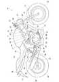
図1は本発明に係る照明装置を備えた自動二輪車の側面図であり、自動二輪車10は、車体フレーム11を備え、この車体フレーム11を、前端に設けたヘッドパイプ12と、このヘッドパイプ12から後方斜め下方に延ばした複数のパイプからなる左右一対のメインフレーム13,14(手前側の符号14のみ示す。)と、これらのメインフレーム13,14の後部にそれぞれ取付けた左右一対のピボットプレート16,17(手前側の符号17のみ示す。)と、これらのピボットプレート16,17の後部上部に取付けた左右一対のシートレール21,22(手前側の符号22のみ示す。)と、これらのシートレール21,22を補強するサブフレーム23,24(手前側の符号24のみ示す。)とで構成した車両である。The best mode for carrying out the present invention will be described below with reference to the accompanying drawings. The drawings are viewed in the direction of the reference numerals.
FIG. 1 is a side view of a motorcycle provided with a lighting device according to the present invention. A
また、自動二輪車10は、ヘッドパイプ12に操舵自在にフロントフォーク31を取付け、このフロントフォーク31の下端に前輪32を取付け、フロントフォーク31の上部にバーハンドル33を取付け、メインフレーム13,14及びピボットプレート16,17にエンジン35を取付け、ピボットプレート16,17にピボット軸36を介してスイングアーム37を上下スイング自在に取付け、このスイングアーム37の後端に後輪38を取付け、ピボットプレート16,17間に設けたクロスパイプ(不図示)及びスイングアーム37のそれぞれにリヤクッションユニット41を渡して取付けたものである。 In the
フロントフォーク31は、左右を連結するトップブリッジ45及びボトムブリッジ46を備え、これらのトップブリッジ45及びボトムブリッジ46に照明装置としてのヘッドランプ47を取付けたものである。 The
エンジン35は、クランクケース51と、このクランクケース51から立ち上げたシリンダ部52とを備え、シリンダ部52を構成するシリンダヘッド53の後部に吸気管54を介してスロットルボディ56を接続し、シリンダヘッド53の前部に排気管57を接続し、後方に延ばした排気管57の後端にマフラ58を接続したものである。 The
また、エンジン35は、内部の潤滑油を冷却するオイルクーラー61を下方に付設したものであり、このオイルクーラー61の後方にはクランクケース51の下部に取付けたオイルパン62が位置する。なお、64はウォータポンプである。 Further, the
図中の71はフロントフェンダ、72はメータ、73はメインフレーム13,14の上部に取付けた燃料タンク、74はシートレール21,22に取付けたシート、76はリヤボディカバー、77はリヤフェンダ、78はエンジン35の前方に配置するためにメインフレーム13,14側のステー81とエンジン35のクランクケース51とに取付けたラジエータ、82,82(手前側の符号82のみ示す。)は運転者用ステップ83,83(手前側の符号83のみ示す。)及び同乗者用ステップ84,84(手前側の符号84のみ示す。)を支持するステップ支持ブラケットである。 In the figure, 71 is a front fender, 72 is a meter, 73 is a fuel tank attached to the upper part of the
図2は本発明に係るヘッドラップ及びその周囲を示す斜視図であり、フロントフォーク31のトップブリッジ45及びボトムブリッジ46に、光源としてLEDを使用したヘッドランプ47を取付け、ヘッドランプ47の下部にブラケット87を介して左右のウインカ88,89を取付けたことを示す。 FIG. 2 is a perspective view showing the head wrap and its surroundings according to the present invention. A
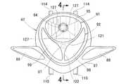
図3は本発明に係るヘッドランプの正面図であり、ヘッドランプ47は、上部に設けたロービーム用ランプ91と、このロービーム用ランプ91の下方に設けたハイビーム用ランプ92とを備える。 FIG. 3 is a front view of a headlamp according to the present invention, and the
ロービーム用ランプ91は、複数のLEDからなるアッパーLED群94と、このアッパーLED群94で発した光を反射させるアッパーリフレクタ95とを備える。
ハイビーム用ランプ92は、複数のLEDからなるロアLED群97と、このロアLED群97で発した光を反射させる左右のロアリフレクタ98,99とを備える。The
The
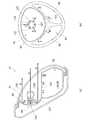
図4は図3の4−4線断面図(図中の矢印(FRONT)は車両前方を表す。)であり、ヘッドランプ47は、ハウジング105と、このハウジング105の前部に取付けたレンズ106と、このレンズ106の内面に取付けたリフレクタ体107とからなり、レンズ106にリフレクタ体107を接着剤108で接着し、ハウジング105にレンズ106を接着剤108で接着する。 4 is a cross-sectional view taken along line 4-4 of FIG. 3 (the arrow (FRONT in the figure represents the front of the vehicle)), and the
ハウジング105は、後部ハウジング111と、この後部ハウジング111に着脱自在に設けた前部ハウジング112とからなり、前部ハウジング112にレンズ106を取付けるときには、後部ハウジング111と前部ハウジング112とを分離し、前部ハウジング112内に後方からレンズ106を挿入して取付ける。なお、114,114(一方の符号114のみ示す。)及び115,115(一方の符号115のみ示す。)は上部ステー及び下部ステーであり、トップブリッジ45及びボトムブリッジ46(図1参照)に取付ける部分である。 The
リフレクタ体107は、アッパーリフレクタ95及びロアリフレクタ98,99(一方の符号98のみ示す。)と、これらのアッパーリフレクタ95とロアリフレクタ98,99との境となる境界壁121と、この境界壁121の中央部とロアリフレクタ98,99の下部前端とを縦に連結する連結壁122とからなる。なお、107aはリフレクタ体107の縁に環状に設けた周縁部であり、レンズ106に接着する部分である。 The
アッパーリフレクタ95は、ほぼ中央に穴部124を設け、この穴部124にロービーム用ランプ91の光源部125を設けた部分である。
光源部125は、穴部124に取付けた3本の爪部127(図3も参照)と、これらの爪部127の中間部に取付けた支持体128と、この支持体128で支持したアッパーLED群94と、3本の爪部127の先端部で把持した球体レンズ129とからなる。The
The
アッパーLED群94は、支持体124に備える縦壁124aの前面に後述するLED単体の軸線が前方を向くように取付けた第1LED群131と、支持体124の後部に備える後方突出部124bの上面及び下面にLED単体の軸線がアッパーリフレクタ95に向くように取付けた第2LED群132とからなる。
第1LED群131及び第2LED群132は、それぞれ複数のLED単体133から構成したものである。The
The
ここでは、別々にロアリフレクタ98,99を設けたが、ロアリフレクタを左右一体の1つのリフレクタとして、連結壁122で2つのリフレクタに見えるようにしてもよい。
境界壁121は、当たった光の一部を透過し、一部を反射させるハーフミラーであり、前端部下部にハイビーム用ランプ92の光源部135を設けた部分である。
光源部135は、境界壁121に取付けた支持体136と、この支持体136の背面に取付けたロアLED群97とからなる。ロアLED群97は、複数のLED単体137から構成したものである。Here, the
The
The
以上に述べたヘッドランプ47の作用を次に説明する。
図5(a),(b)は本発明に係るヘッドランプの作用を示す第1作用図である。
(a)において、ロービーム用ランプ91の第1LED群131及び第2LED群132を点灯すると、第1LED群131から発した光は、矢印Aで示すように、球体レンズ129を通過して前方に進む。球体レンズ129を通過した一部の光は拡散して広い範囲を照らすことができる。Next, the operation of the
FIGS. 5A and 5B are first operation diagrams showing the operation of the headlamp according to the present invention.
In (a), when the
また、第2LED群132から発した光は、矢印B,Cで示すように、アッパーリフレクタ95に向かい、アッパーリフレクタ95で反射して、矢印D,Eで示すように前方に進む。 Further, the light emitted from the
更に、第1LED群131及び第2LED群132から発した光は、矢印F,Gで示すように、ハーフミラーである境界壁121を通過してハイビーム用ランプ92側に入り込む。 Further, the light emitted from the
(b)において、ロービーム用ランプ91の第1LED群132から発した光は、矢印H,J,Kで示すように、3本の爪部127の間を通ってアッパーリフレクタ95に当たり、アッパーリフレクタ95で反射する。 In (b), the light emitted from the
また、ロービーム用ランプ91側の光が、矢印L〜N,Pで示すように、境界壁121を通過してハイビーム用ランプ92側に至り、ロアリフレクタ98,99で反射してハイビーム用ランプ92をほのかに発光させる。 Further, as indicated by arrows L to N and P, the light on the
以上の(a),(b)に示したように、ロービーム用ランプ91の光源を、前方を直接照らす第1LED群131と、アッパーリフレクタ95で反射させて前方を照らす第2LED群132とで構成したことで、明るい照明装置を得ることができる。 As shown in (a) and (b) above, the light source of the
図6(a),(b)は本発明に係るヘッドランプの作用を示す第2作用図である。
(a)において、ハイビーム用ランプ92のロアLED群97を点灯すると、ロアLED群97から発した光は、矢印Qで示すように、ロアリフレクタ98,99に向かい、矢印Rで示すように、ロアリフレクタ98,99で反射して前方へ進む。
また、ロアLED群97から発した光は、矢印S,Tで示すように、境界壁121を通過してロービーム用ランプ91側に入り込む。FIGS. 6A and 6B are second operation diagrams showing the operation of the headlamp according to the present invention.
In (a), when the
Further, the light emitted from the
(b)において、ハイビーム用ランプ92側の光が、矢印V〜Yで示すように、境界壁121を通過してロービーム用ランプ91側に至り、アッパーリフレクタ95で反射してロービーム用ランプ91をほのかに発光させる。 In (b), as indicated by arrows V to Y, the light on the
以上の図5(b)及び図6(b)で示したように、ロービーム用ランプ91及びハイビーム用ランプ92の一方を点灯したときに、ロービーム用ランプ91及びハイビーム用ランプ92の他方を発光させることができるため、常にヘッドランプ47の全体を発光させることができ、遠くからのヘッドランプ47の視認性を向上させることができる。 As shown in FIGS. 5B and 6B, when one of the
以上の図4で示したように、本発明は第1に、前方に向いた第1の光源としての第1LED群131と、この第1LED群131よりも後方に位置するとともに前方を向いたアッパーリフレクタ95とを備えた照明装置としてのヘッドランプ47において、第1LED群131の後方にアッパーリフレクタ95に向けて光を照射する第2の光源としての第2LED群132を設けたことを特徴とする。 As shown in FIG. 4, the present invention firstly includes a
これにより、第1LED群131からの直接光と、アッパーリフレクタによる第2LED群132の反射光とによって前方を明るく照らすことができ、明るいヘッドランプ47を得ることができる。 Thereby, the front can be brightly illuminated by the direct light from the
本発明は第2に、図3及び図4に示したように、第2LED群132を、第1LED群131と正面から見て重なり合う位置に配置したことを特徴とする。
これにより、ヘッドランプ47、詳しくは、光源部125の上下及び左右の寸法を小さくすることができ、ヘッドランプ47の小型化、コンパクト化を図ることができる。また、光源部125が小さくなるため、アッパーリフレクタ95の反射面積を大きくすることができる。Secondly, the present invention is characterized in that, as shown in FIGS. 3 and 4, the
Thereby, the vertical and horizontal dimensions of the
本発明は第3に、図4に示したように、第2LED群132を構成するLED単体131の軸線131aをアッパーリフレクタ95に向けて配置したことを特徴とする。
これにより、第2LED群132の光を効率良くアッパーリフレクタ95に当てることができ、ヘッドランプ47をより明るくすることができる。Thirdly, as shown in FIG. 4, the present invention is characterized in that the axis 131 a of the
Thereby, the light of the
本発明は第4に、第1LED群131及び第2LED群132を、LED、即ちLED単体131で構成したことを特徴とする。
これにより、消費電力を抑えながら所定の明るさを確保することができ、バッテリの容量を小さくすることができる。Fourthly, the present invention is characterized in that the
Thereby, predetermined brightness can be ensured while suppressing power consumption, and the capacity of the battery can be reduced.
本発明は第5に、第1LED群131の前方に光を拡散する球体レンズ129を配置したことを特徴とする。
第1LED群131の前方に光を拡散する球体レンズ129を配置したので、第1LED群131の光の照射範囲を広げることができる。Fifth, the present invention is characterized in that a
Since the
本発明は第6に、図4〜図6に示したように、一つの灯体ハウジングとしてのハウジング105内にロービーム用光源としてのアッパーLED群94と、ハイビーム用光源としてのロアLED群97を配置したヘッドランプ47において、アッパーLED群94とロアLED群97とを隔壁としての境界壁121により区画するとともに、その境界壁21をハーフミラーで構成したことを特徴とする。 As shown in FIGS. 4 to 6, the present invention sixthly includes an
これにより、アッパーLED群94及びロアLED群97の一方を点灯したときに、境界壁121を通してアッパーLED群94及びロアLED群97の他方に光を供給することができ、アッパーLED群94及びロアLED群97の両方が光って見え、ヘッドランプ47の遠方からの視認性を向上させることができる。 Accordingly, when one of the
本発明は第7に、図3及び図4に示したように、アッパーLED群94の光を反射するアッパーリフレクタ95を正面視でほぼ円形にするとともに、ロアLED群97の光を反射するロアリフレクタ98,99を正面視でアッパーリフレクタ95に沿うように細長く形成し、ロアLED群97をロアリフレクタ98,99の前方に配置するとともにロアリフレクタ98,99に向くようにしたことを特徴とする。 The present invention seventhly, as shown in FIGS. 3 and 4, the
これにより、アッパーリフレクタ95とロアリフレクタ98,99との一体感を高めることができ、また、ハイビーム用ランプ92では、ロアリフレクタ98,99のみによる反射光の制御を行うことができ、反射光の制御が容易になる。 As a result, the sense of unity between the
尚、本発明では、ロービーム用光源の光を反射するリフレクタを正面視でほぼ円形にしたが、これに限らず、横長の楕円、横長の長円、あるいはこれらに類似する形状にしてもよい。 In the present invention, the reflector for reflecting the light of the low beam light source is made into a substantially circular shape when viewed from the front. However, the reflector is not limited to this, and may be a horizontally long ellipse, a horizontally long ellipse, or a similar shape.
本発明の照明装置は、二輪車に好適である。 The illumination device of the present invention is suitable for a motorcycle.
10…自動二輪車、47…照明装置(ヘッドランプ)、94…ロービーム用光源(アッパーLED群)、95,98,99…リフレクタ、97…ハイビーム用光源(ロアLED群)、105…灯体ハウジング(ハウジング)、121…隔壁(境界壁)、129…レンズ(球体レンズ)、131…第1の光源(第1LED群)、132…第2の光源(第2LED群)、133,137…LED(LED単体)、133a…第2の光源の軸線。 DESCRIPTION OF
Claims (7)
Translated fromJapanese前記第1の光源の後方に前記リフレクタに向けて光を照射する第2の光源を設けたことを特徴とする照明装置。In an illuminating device comprising a first light source facing forward, and a reflector located rearward of the first light source and facing forward,
2. A lighting device, comprising: a second light source that irradiates light toward the reflector behind the first light source.
前記ロービーム用光源と前記ハイビーム用光源とを隔壁により区画するとともに、その隔壁をハーフミラーで構成したことを特徴とする照明装置。In a lighting device in which a low beam light source and a high beam light source are arranged in one lamp housing,
An illumination device characterized in that the low-beam light source and the high-beam light source are partitioned by a partition, and the partition is configured by a half mirror.
Priority Applications (1)
| Application Number | Priority Date | Filing Date | Title |
|---|---|---|---|
| JP2005218734AJP4508971B2 (en) | 2005-07-28 | 2005-07-28 | Lighting device |
Applications Claiming Priority (1)
| Application Number | Priority Date | Filing Date | Title |
|---|---|---|---|
| JP2005218734AJP4508971B2 (en) | 2005-07-28 | 2005-07-28 | Lighting device |
Publications (2)
| Publication Number | Publication Date |
|---|---|
| JP2007035499Atrue JP2007035499A (en) | 2007-02-08 |
| JP4508971B2 JP4508971B2 (en) | 2010-07-21 |
Family
ID=37794495
Family Applications (1)
| Application Number | Title | Priority Date | Filing Date |
|---|---|---|---|
| JP2005218734AExpired - Fee RelatedJP4508971B2 (en) | 2005-07-28 | 2005-07-28 | Lighting device |
Country Status (1)
| Country | Link |
|---|---|
| JP (1) | JP4508971B2 (en) |
Cited By (10)
| Publication number | Priority date | Publication date | Assignee | Title |
|---|---|---|---|---|
| EP2050665A1 (en)* | 2007-10-10 | 2009-04-22 | Yamaha Hatsudoki Kabushiki Kaisha | Straddle-type vehicle |
| JP2010195380A (en)* | 2009-01-29 | 2010-09-09 | Honda Motor Co Ltd | Lighting system for vehicle |
| WO2012120947A1 (en)* | 2011-03-04 | 2012-09-13 | 本田技研工業株式会社 | Lighting device for vehicle, and mounting structure for the device |
| JP2013177104A (en)* | 2012-02-29 | 2013-09-09 | Honda Motor Co Ltd | Headlight of motorcycle |
| WO2013145895A1 (en)* | 2012-03-29 | 2013-10-03 | 本田技研工業株式会社 | Headlight device of motorcycle |
| CN103486520A (en)* | 2013-09-30 | 2014-01-01 | 长城汽车股份有限公司 | LED light source headlamp |
| CN103507881A (en)* | 2012-11-09 | 2014-01-15 | 广州市雷腾照明科技有限公司 | LED motorcycle headlamp with long-distance light and short-distance light capable of being adjusted |
| EP2918448A1 (en) | 2014-03-11 | 2015-09-16 | Honda Motor Co., Ltd. | Light device for vehicle |
| US20160236743A1 (en)* | 2013-10-10 | 2016-08-18 | Honda Motor Company Limited | Led headlight structure for motorcycle |
| CN106627873A (en)* | 2015-10-30 | 2017-05-10 | 雅马哈发动机株式会社 | Striding vehicle |
Citations (2)
| Publication number | Priority date | Publication date | Assignee | Title |
|---|---|---|---|---|
| JPH09265807A (en)* | 1996-03-29 | 1997-10-07 | Toshiba Lighting & Technol Corp | LED light source, LED signal light and traffic light |
| JPH10144108A (en)* | 1996-11-05 | 1998-05-29 | Shizuoka Keisozai Kk | Headlight device for vehicle |
- 2005
- 2005-07-28JPJP2005218734Apatent/JP4508971B2/ennot_activeExpired - Fee Related
Patent Citations (2)
| Publication number | Priority date | Publication date | Assignee | Title |
|---|---|---|---|---|
| JPH09265807A (en)* | 1996-03-29 | 1997-10-07 | Toshiba Lighting & Technol Corp | LED light source, LED signal light and traffic light |
| JPH10144108A (en)* | 1996-11-05 | 1998-05-29 | Shizuoka Keisozai Kk | Headlight device for vehicle |
Cited By (19)
| Publication number | Priority date | Publication date | Assignee | Title |
|---|---|---|---|---|
| EP2050665A1 (en)* | 2007-10-10 | 2009-04-22 | Yamaha Hatsudoki Kabushiki Kaisha | Straddle-type vehicle |
| JP2010195380A (en)* | 2009-01-29 | 2010-09-09 | Honda Motor Co Ltd | Lighting system for vehicle |
| JP5531153B2 (en)* | 2011-03-04 | 2014-06-25 | 本田技研工業株式会社 | LIGHTING DEVICE FOR VEHICLE AND MOUNTING STRUCTURE FOR THE DEVICE |
| WO2012120947A1 (en)* | 2011-03-04 | 2012-09-13 | 本田技研工業株式会社 | Lighting device for vehicle, and mounting structure for the device |
| US9080737B2 (en) | 2011-03-04 | 2015-07-14 | Honda Motor Co., Ltd. | Lighting device for vehicle, and mounting structure for the device |
| AU2012225991B2 (en)* | 2011-03-04 | 2015-06-04 | Honda Motor Co., Ltd. | Lighting device for vehicle, and mounting structure for the device |
| JP2013177104A (en)* | 2012-02-29 | 2013-09-09 | Honda Motor Co Ltd | Headlight of motorcycle |
| CN104203736A (en)* | 2012-03-29 | 2014-12-10 | 本田技研工业株式会社 | Headlight device of motorcycle |
| WO2013145895A1 (en)* | 2012-03-29 | 2013-10-03 | 本田技研工業株式会社 | Headlight device of motorcycle |
| US9593817B2 (en) | 2012-03-29 | 2017-03-14 | Honda Motor Co., Ltd. | Headlight device of motorcycle |
| CN103507881A (en)* | 2012-11-09 | 2014-01-15 | 广州市雷腾照明科技有限公司 | LED motorcycle headlamp with long-distance light and short-distance light capable of being adjusted |
| CN103507881B (en)* | 2012-11-09 | 2016-01-20 | 广州市雷腾照明科技有限公司 | A kind of LED motorcycle front car light of adjustable distance-light |
| CN103486520A (en)* | 2013-09-30 | 2014-01-01 | 长城汽车股份有限公司 | LED light source headlamp |
| US20160236743A1 (en)* | 2013-10-10 | 2016-08-18 | Honda Motor Company Limited | Led headlight structure for motorcycle |
| US9944340B2 (en)* | 2013-10-10 | 2018-04-17 | Honda Motor Co., Ltd. | LED headlight structure for motorcycle |
| EP2918448A1 (en) | 2014-03-11 | 2015-09-16 | Honda Motor Co., Ltd. | Light device for vehicle |
| US10030834B2 (en) | 2014-03-11 | 2018-07-24 | Honda Motor Co., Ltd. | Light device for vehicle |
| CN106627873A (en)* | 2015-10-30 | 2017-05-10 | 雅马哈发动机株式会社 | Striding vehicle |
| CN106627873B (en)* | 2015-10-30 | 2019-05-07 | 雅马哈发动机株式会社 | Straddle-type vehicle |
Also Published As
| Publication number | Publication date |
|---|---|
| JP4508971B2 (en) | 2010-07-21 |
Similar Documents
| Publication | Publication Date | Title |
|---|---|---|
| US8118460B2 (en) | Motorcycle headlamp | |
| CN100570206C (en) | Vehicle headlight structure | |
| CN101788123B (en) | Position light and lighting apparatus for motorcycle | |
| JP6116935B2 (en) | Motorcycle headlamp device | |
| JP4175543B2 (en) | Vehicle tail lamp | |
| JP4508971B2 (en) | Lighting device | |
| JP4086227B2 (en) | Rearview mirror device | |
| JP2018511919A (en) | Light fixture structure with auxiliary lighting | |
| JP5211020B2 (en) | Front lighting structure of saddle-ride type vehicle | |
| CN107429893A (en) | Headlamp | |
| CN108372896B (en) | Vehicle lighting device | |
| CN107429898B (en) | headlamp | |
| JP4707112B2 (en) | Motorcycle rear lighting system | |
| CN100572898C (en) | Two-wheeled rear combination lamp structure | |
| JP4545325B2 (en) | Motorcycle headlight device | |
| JP6885982B2 (en) | Headlight structure of saddle-riding vehicle | |
| JP7124118B2 (en) | Straddle-type vehicle lighting device | |
| JP2006290232A (en) | Vehicle lamp structure | |
| CN100572895C (en) | Structure of lamps for vehicles | |
| JP4510736B2 (en) | Headlight device for saddle-ride type vehicles | |
| JP2008277239A (en) | Headlight structure | |
| JP4804333B2 (en) | Light | |
| CN109070958B (en) | Headlamp device for saddle-riding vehicle | |
| CN100462622C (en) | vehicle lights | |
| JP5564011B2 (en) | Rear structure of the vehicle |
Legal Events
| Date | Code | Title | Description |
|---|---|---|---|
| A621 | Written request for application examination | Free format text:JAPANESE INTERMEDIATE CODE: A621 Effective date:20071127 | |
| A977 | Report on retrieval | Free format text:JAPANESE INTERMEDIATE CODE: A971007 Effective date:20090826 | |
| A131 | Notification of reasons for refusal | Free format text:JAPANESE INTERMEDIATE CODE: A131 Effective date:20090902 | |
| A521 | Request for written amendment filed | Free format text:JAPANESE INTERMEDIATE CODE: A523 Effective date:20091023 | |
| TRDD | Decision of grant or rejection written | ||
| A01 | Written decision to grant a patent or to grant a registration (utility model) | Free format text:JAPANESE INTERMEDIATE CODE: A01 Effective date:20100427 | |
| A01 | Written decision to grant a patent or to grant a registration (utility model) | Free format text:JAPANESE INTERMEDIATE CODE: A01 | |
| A61 | First payment of annual fees (during grant procedure) | Free format text:JAPANESE INTERMEDIATE CODE: A61 Effective date:20100427 | |
| FPAY | Renewal fee payment (event date is renewal date of database) | Free format text:PAYMENT UNTIL: 20130514 Year of fee payment:3 | |
| R150 | Certificate of patent or registration of utility model | Ref document number:4508971 Country of ref document:JP Free format text:JAPANESE INTERMEDIATE CODE: R150 Free format text:JAPANESE INTERMEDIATE CODE: R150 | |
| FPAY | Renewal fee payment (event date is renewal date of database) | Free format text:PAYMENT UNTIL: 20130514 Year of fee payment:3 | |
| FPAY | Renewal fee payment (event date is renewal date of database) | Free format text:PAYMENT UNTIL: 20140514 Year of fee payment:4 | |
| LAPS | Cancellation because of no payment of annual fees |