JP2007035151A - Semiconductor memory device and refresh control method of memory system - Google Patents
Semiconductor memory device and refresh control method of memory systemDownload PDFInfo
- Publication number
- JP2007035151A JP2007035151AJP2005216429AJP2005216429AJP2007035151AJP 2007035151 AJP2007035151 AJP 2007035151AJP 2005216429 AJP2005216429 AJP 2005216429AJP 2005216429 AJP2005216429 AJP 2005216429AJP 2007035151 AJP2007035151 AJP 2007035151A
- Authority
- JP
- Japan
- Prior art keywords
- refresh
- bank
- auto
- banks
- command
- Prior art date
- Legal status (The legal status is an assumption and is not a legal conclusion. Google has not performed a legal analysis and makes no representation as to the accuracy of the status listed.)
- Pending
Links
- 239000004065semiconductorSubstances0.000titleclaimsabstractdescription33
- 238000000034methodMethods0.000titleclaimsdescription27
- 230000004044responseEffects0.000claimsabstractdescription5
- 230000002093peripheral effectEffects0.000abstract1
- 230000006870functionEffects0.000description7
- 230000000052comparative effectEffects0.000description5
- 240000007320Pinus strobusSpecies0.000description4
- 238000010586diagramMethods0.000description4
- 230000008859changeEffects0.000description2
- 230000000694effectsEffects0.000description2
- 230000004048modificationEffects0.000description2
- 238000012986modificationMethods0.000description2
- 230000001360synchronised effectEffects0.000description2
- 238000003491arrayMethods0.000description1
- 230000003111delayed effectEffects0.000description1
- 230000014759maintenance of locationEffects0.000description1
- 239000011159matrix materialSubstances0.000description1
- 230000008569processEffects0.000description1
- 238000011084recoveryMethods0.000description1
- 230000009467reductionEffects0.000description1
Images


Classifications
- G—PHYSICS
- G11—INFORMATION STORAGE
- G11C—STATIC STORES
- G11C11/00—Digital stores characterised by the use of particular electric or magnetic storage elements; Storage elements therefor
- G11C11/21—Digital stores characterised by the use of particular electric or magnetic storage elements; Storage elements therefor using electric elements
- G11C11/34—Digital stores characterised by the use of particular electric or magnetic storage elements; Storage elements therefor using electric elements using semiconductor devices
- G11C11/40—Digital stores characterised by the use of particular electric or magnetic storage elements; Storage elements therefor using electric elements using semiconductor devices using transistors
- G11C11/401—Digital stores characterised by the use of particular electric or magnetic storage elements; Storage elements therefor using electric elements using semiconductor devices using transistors forming cells needing refreshing or charge regeneration, i.e. dynamic cells
- G11C11/406—Management or control of the refreshing or charge-regeneration cycles
- G11C11/40622—Partial refresh of memory arrays
Landscapes
- Engineering & Computer Science (AREA)
- Microelectronics & Electronic Packaging (AREA)
- Computer Hardware Design (AREA)
- Dram (AREA)
- For Increasing The Reliability Of Semiconductor Memories (AREA)
Abstract
Description
Translated fromJapanese本発明は、メモリアレイを複数のバンクに分割し、各バンクのリード動作やライト動作を独立に制御可能な半導体メモリ装置に関し、特に通常動作時に所定のリフレッシュインターバルで各バンクのオートリフレッシュ動作を実行可能に構成されたDRAM(Dynamic Random Access Memory)等の半導体メモリ装置、及び、その半導体メモリ装置を含むメモリシステムに関するものである。 The present invention relates to a semiconductor memory device that can divide a memory array into a plurality of banks and independently control the read operation and write operation of each bank. In particular, the auto refresh operation of each bank is executed at a predetermined refresh interval during normal operation. The present invention relates to a semiconductor memory device such as a DRAM (Dynamic Random Access Memory) and a memory system including the semiconductor memory device.
一般にDRAMにおいてはメモリアレイを複数のバンクに分割し、DRAMのリード動作やライト動作を各々のバンクに対して独立に制御できるように構成されている。例えば、DRAMを4バンクで構成する場合、2ビットのバンクアドレスを付加して各種のコマンドを発行することにより、4バンクのうちの所望の1バンクのみを活性化してリード動作やライト動作を行うことができる。 In general, a DRAM is configured such that a memory array is divided into a plurality of banks, and a read operation and a write operation of the DRAM can be controlled independently for each bank. For example, when the DRAM is composed of 4 banks, by adding various 2-bit bank addresses and issuing various commands, only a desired one of the 4 banks is activated and a read operation or a write operation is performed. be able to.
一方、DRAMのメモリセルに電荷として記憶されるデータを保持するために所定のリフレッシュ周期でリフレッシュ動作を実行する必要がある。一般に、通常動作時において所定のインターバルでリフレッシュカウンタによりカウントアップされる行アドレスを対象にリフレッシュを行うオートリフレッシュ機能が採用される。基本的に全てのバンクについてリフレッシュ動作に伴う制御は共通に行うことができ、全バンクに対して同時にリフレッシュ動作が実行される。例えば、リフレッシュ周期が64msでワード線数が8192本であるとすると、7.8μsのリフレッシュインターバルが経過する度に、全バンクに対するオートリフレッシュが繰り返し実行されることになる。 On the other hand, it is necessary to perform a refresh operation at a predetermined refresh period in order to hold data stored as electric charges in a DRAM memory cell. In general, an auto-refresh function is employed that performs refresh for a row address that is counted up by a refresh counter at a predetermined interval during normal operation. Basically, the control associated with the refresh operation can be performed in common for all banks, and the refresh operation is executed simultaneously for all banks. For example, assuming that the refresh cycle is 64 ms and the number of word lines is 8192, auto refresh for all banks is repeatedly executed every time the refresh interval of 7.8 μs elapses.
また、リフレッシュ動作を全てのバンクに対して同時に実行することは、リフレッシュ動作中のピーク電流の増大やバスの使用効率の低下などを招く可能性があることから、複数のバンクのうち一部のバンクのみを対象としてリフレッシュ動作を実行制御するDRAMが提案されている(例えば、特許文献1及び2参照)。 In addition, performing the refresh operation on all banks at the same time may cause an increase in peak current during the refresh operation and a decrease in bus use efficiency. There has been proposed a DRAM that controls execution of a refresh operation only for a bank (see, for example,
DRAMに対する上記のオートリフレッシュは、リフレッシュ対象のバンクがリード動作やライト動作の実行中であるか否かを問わずリフレッシュインターバルのタイミングで実行する必要がある。しかし、リフレッシュ対象のバンクがアイドル状態であるときは直ちにリフレッシュ動作を開始できるのに対し、リフレッシュ対象のバンクがリード動作やライト動作によりビジー状態にあるときは、リフレッシュ動作に際して複雑な制御が求められる。ここで、ビジー状態とはバンクがアクティブ状態にあることを意味し、アイドル状態とはバンクが非アクティブ状態にあることを意味する。すなわち、リフレッシュ対象のバンクの動作を中断して速やかにプリチャージ動作を実行し、そのバンクをアイドル状態に移行させた後にリフレッシュ動作を実行し、リフレッシュ動作の完了後にバンクをアクティブ状態にして中断された動作を再開する手順で制御を行う。このような一連の手順は相当のクロック数を要し、リフレッシュインターバルが短いことを考えると処理時間が累積されて制御の負荷が増大する。しかも、全バンクのリフレッシュ動作を同時に実行する場合にビジー状態のバンクが一つでもあれば必要となる制御であり、全体的にかなり頻繁に上記の手順が実行されることになり、DRAMの動作効率の低減を招くことが問題となる。 The above-described auto-refresh for the DRAM needs to be performed at the refresh interval timing regardless of whether the refresh target bank is executing a read operation or a write operation. However, when the refresh target bank is in an idle state, the refresh operation can be started immediately, whereas when the refresh target bank is in a busy state by a read operation or a write operation, complicated control is required for the refresh operation. . Here, the busy state means that the bank is in an active state, and the idle state means that the bank is in an inactive state. In other words, the operation of the bank to be refreshed is interrupted and the precharge operation is immediately executed, the refresh operation is executed after the bank is shifted to the idle state, and the bank is activated and interrupted after the refresh operation is completed. Control is performed with the procedure to resume the operation. Such a series of procedures requires a considerable number of clocks, and considering that the refresh interval is short, the processing time is accumulated and the control load increases. In addition, when the refresh operation of all the banks is executed at the same time, the control is necessary if there is even one busy bank, and the above procedure is executed quite frequently as a whole. Incurring a reduction in efficiency is a problem.
この点については、特許文献1、2に記載されているように複数のバンクのうち一部のバンクのみを対象としてリフレッシュ動作を実行する場合も、ビジー状態のバンクに対して上記の手順が求められる点で同様の問題がある。 With respect to this point, as described in
そこで、本発明はこれらの問題を解決するためになされたものであり、複数のバンクに分割されたメモリアレイに対するリフレッシュ動作を実行する場合、ビジー状態にあるバンクに対する複雑な制御を不要とし、短時間でリフレッシュ動作を確実に完了させ、動作効率の良好な半導体メモリ装置を提供することを目的とする。 Therefore, the present invention has been made to solve these problems. When a refresh operation is performed on a memory array divided into a plurality of banks, complicated control for a busy bank is not required, and a short operation is performed. An object of the present invention is to provide a semiconductor memory device that can reliably complete a refresh operation in time and has good operation efficiency.
上記課題を解決するために、本発明の半導体メモリ装置は、それぞれ独立に制御可能な複数のバンクに分割されたメモリアレイを備え、当該メモリアレイに対するリフレッシュ動作を実行する半導体メモリ装置であって、前記複数のバンクの各々に設けられ、リフレッシュ対象の行アドレスを発生するリフレッシュアドレス発生回路と、前記複数のバンクの中から任意の組合せで選択されたバンクを示すバンク選択情報が付加されたリフレッシュ要求に応じて、前記バンク選択情報に基づき選択されたバンクに対する前記リフレッシュ動作を実行する一方、前記バンク選択情報に基づき選択されないバンクに対する前記リフレッシュ動作を実行しないように制御する制御回路を備えている。 In order to solve the above problems, a semiconductor memory device of the present invention is a semiconductor memory device including a memory array divided into a plurality of banks that can be controlled independently, and performing a refresh operation on the memory array, A refresh request provided in each of the plurality of banks, to which a refresh address generating circuit for generating a row address to be refreshed, and bank selection information indicating a bank selected in any combination from the plurality of banks is added. And a control circuit for performing control so as not to execute the refresh operation for a bank not selected based on the bank selection information while executing the refresh operation for the bank selected based on the bank selection information.
このように、本発明の半導体メモリ装置によれば、メモリアレイのリフレッシュ動作を実行するとき、動作状態に応じてリフレッシュ対象とすべきバンクのみを自在に選択してリフレッシュ要求を行うことができる。リフレッシュ対象として選択されたバンクについては、行アドレス発生回路が発生する行アドレスのリフレッシュ動作が実行され、リフレッシュ対象として非選択のバンクについては、かかるリフレッシュ動作が実行されない。よって、リフレッシュ要求時に動作中のバンクをリフレッシュするときに必要となる制御(すなわち、バンクの動作をいったん中断してリフレッシュ後に再開するなどの一連の手順)が不要となり、毎回のリフレッシュ動作を迅速に完了させることで、半導体メモリ装置の動作効率を向上させることができる。 As described above, according to the semiconductor memory device of the present invention, when performing the refresh operation of the memory array, it is possible to make a refresh request by freely selecting only the bank to be refreshed according to the operation state. For the bank selected as the refresh target, the refresh operation of the row address generated by the row address generation circuit is executed, and for the bank not selected as the refresh target, the refresh operation is not executed. Therefore, the control necessary for refreshing the bank in operation at the time of the refresh request (that is, a series of procedures such as interrupting the operation of the bank and restarting it after the refresh) is unnecessary, and each refresh operation can be performed quickly. By completing the operation, the operation efficiency of the semiconductor memory device can be improved.
本発明の半導体メモリ装置において、前記バンク選択情報は、N個のバンクの各々に対する選択の有無を含む2N通りの組合せに対応するNビットの情報としてもよい。In the semiconductor memory device of the present invention, the bank selection information may be N-bit information corresponding to 2N combinations including whether or not each of the N banks is selected.
この場合、前記Nビットのバンク選択情報は、前記リフレッシュ要求の際に外部入力されるアドレスに含まれる所定のNビットに割り当てることができる。 In this case, the N-bit bank selection information can be assigned to predetermined N bits included in an address input externally at the time of the refresh request.
本発明の半導体メモリ装置において、前記リフレッシュ動作は、通常動作時に所定のリフレッシュインターバルで順次実行されるオートリフレッシュ動作であり、前記バンク選択情報に基づき選択されたバンクに対応する前記リフレッシュアドレス発生回路は、前記リフレッシュインターバルごとに前記リフレッシュ対象の行アドレスを更新するように構成してもよい。 In the semiconductor memory device of the present invention, the refresh operation is an auto-refresh operation that is sequentially executed at a predetermined refresh interval during a normal operation, and the refresh address generation circuit corresponding to the bank selected based on the bank selection information is The row address to be refreshed may be updated at each refresh interval.
本発明の半導体メモリ装置において、前記オートリフレッシュ動作を要求する2種のコマンドとして、前記バンク選択情報により選択されたバンクのオートリフレッシュ動作を要求するバンク選択オートリフレッシュコマンドと、全てのバンクのオートリフレッシュ動作を要求する通常オートリフレッシュコマンドを規定し、前記制御回路は、前記バンク選択オートリフレッシュコマンドと前記通常オートリフレッシュコマンドを判別し、要求された前記オートリフレッシュ動作を実行制御するようにしてもよい。 In the semiconductor memory device of the present invention, the bank selection auto-refresh command for requesting the auto-refresh operation for the bank selected by the bank selection information and the auto-refresh for all banks as the two types of commands for requesting the auto-refresh operation. A normal auto-refresh command requesting an operation may be defined, and the control circuit may discriminate between the bank selection auto-refresh command and the normal auto-refresh command and execute and control the requested auto-refresh operation.
この場合、前記バンク選択オートリフレッシュコマンドと前記通常オートリフレッシュに対し、共通のオートリフレッシュコマンドを規定し、前記制御回路が、前記バンク選択オートリフレッシュと前記通常オートリフレッシュを切り替え可能に設定する設定情報をモードレジスタに保持し、前記共通のオートリフレッシュコマンドが発行されたとき、前記モードレジスタに保持される前記設定情報に基づいて前記バンク選択オートリフレッシュコマンドと前記通常オートリフレッシュコマンドのいずれであるかを判別するようにしてもよい。 In this case, a common auto-refresh command is defined for the bank selection auto-refresh command and the normal auto-refresh, and the control circuit sets setting information for setting the bank-select auto-refresh and the normal auto-refresh so as to be switchable. When it is held in the mode register and the common auto-refresh command is issued, it is determined whether it is the bank selection auto-refresh command or the normal auto-refresh command based on the setting information held in the mode register You may make it do.
上記課題を解決するために、本発明のメモリシステムのリフレッシュ制御方法は、それぞれ独立に制御可能な複数のバンクに分割されたメモリアレイを備え、前記複数のバンクの中から選択されたバンクに対するリフレッシュ動作を実行制御する半導体メモリ装置を含むメモリシステムのリフレッシュ制御方法であって、前記リフレッシュ動作を行う所定のタイミングで、前記複数のバンクの各々がビジー状態であるか否かを判断し、ビジー状態ではないバンクのみを示すバンク選択情報を決定し、当該決定されたバンク選択情報を付加してリフレッシュ要求を行い、前記リフレッシュ要求を受けた前記半導体メモリ装置において、前記バンク選択情報に基づき選択されたバンクに対する前記リフレッシュ動作を実行する一方、前記バンク選択情報に基づき選択されないバンクに対する前記リフレッシュ動作を実行しないように制御する。 In order to solve the above problems, a refresh control method for a memory system according to the present invention comprises a memory array divided into a plurality of banks that can be controlled independently, and refreshes a bank selected from the plurality of banks. A refresh control method for a memory system including a semiconductor memory device that controls the execution of an operation, wherein at a predetermined timing for performing the refresh operation, it is determined whether each of the plurality of banks is in a busy state. Bank selection information indicating only non-banks is determined, a refresh request is made by adding the determined bank selection information, and the semiconductor memory device that has received the refresh request is selected based on the bank selection information While performing the refresh operation on the bank, the bank selection The controlled not to execute the refresh operation for the unselected bank based on the information.
本発明のメモリシステムの制御方法において、前記バンク選択情報は、前記半導体メモリ装置のN個のバンクの各々に対する選択の有無を含む2N通りの組合せに対応するNビットの情報としてもよい。In the memory system control method of the present invention, the bank selection information may be N-bit information corresponding to 2N combinations including whether or not each of the N banks of the semiconductor memory device is selected.
本発明のメモリシステムの制御方法において、前記リフレッシュ動作は、通常動作時に所定のリフレッシュインターバルで順次実行されるオートリフレッシュ動作であり、前記バンク選択情報により選択されたバンクのオートリフレッシュ動作を要求するバンク選択オートリフレッシュコマンドを規定してもよい。 In the memory system control method of the present invention, the refresh operation is an auto-refresh operation that is sequentially executed at a predetermined refresh interval during a normal operation, and a bank that requests an auto-refresh operation of a bank selected by the bank selection information. A selection auto-refresh command may be defined.
本発明のメモリシステムの制御方法において、前記リフレッシュインターバルごとに、ビジー状態ではないバンクを選択して前記バンク選択情報を決定し、当該決定されたバンク選択情報が付加された前記バンク選択オートリフレッシュコマンドを発行するようにしてもよい。 In the memory system control method of the present invention, for each refresh interval, a bank that is not busy is selected to determine the bank selection information, and the bank selection auto-refresh command to which the determined bank selection information is added May be issued.
この場合、所定回数の前記リフレッシュインターバルを含む期間ごとに、前記選択オートリフレッシュコマンドに応じてバンクごとに実行されたオートリフレッシュ動作の実行回数が前記所定回数に不足する場合、少なくとも各バンクの不足回数分が充足される回数のオートリフレッシュ動作を実行制御するようにしてもよい。 In this case, if the number of executions of the auto-refresh operation executed for each bank in response to the selected auto-refresh command is insufficient for the predetermined number for each period including the predetermined number of refresh intervals, at least the number of shortages for each bank. The auto refresh operation may be executed and controlled as many times as the minutes are satisfied.
本発明によれば、複数のバンクに分割されたメモリアレイを備える半導体メモリ装置に対するリフレッシュ動作は、複数のバンクの中から任意の組合せで選択されたバンクのみを対象として実行できるようにしたので、特定のバンクがリード動作やライト動作のためにビジー状態であるときは、リフレッシュ対象から除外することができる。よって、リフレッシュ時にバンクの動作をいったん停止して再開するまでの一連の手順が不要となり、毎回のリフレッシュ動作を速やかに完了させることができ、半導体メモリ装置の動作効率の向上を実現することが可能となる。 According to the present invention, a refresh operation for a semiconductor memory device including a memory array divided into a plurality of banks can be executed only for banks selected in any combination from the plurality of banks. When a specific bank is busy for a read operation or a write operation, it can be excluded from refresh targets. Therefore, a series of steps from temporarily stopping and restarting the bank operation at the time of refresh becomes unnecessary, and each refresh operation can be completed promptly, thereby improving the operation efficiency of the semiconductor memory device. It becomes.
以下、本発明の実施形態について図面を参照しながら説明する。本実施形態では、低消費電力化を目的とした長周期リフレッシュ動作を実行可能な構成を備えたDRAM(Dynamic Random Access Memory)等の半導体メモリ装置を含むメモリシステムに対して本発明を適用する。ここでは、同期型のDRAMとして、4バンク構成のDDR−SDRAM(Double Data Rate Synchronous DRAM)を用いる場合の構成を説明する。 Hereinafter, embodiments of the present invention will be described with reference to the drawings. In the present embodiment, the present invention is applied to a memory system including a semiconductor memory device such as a DRAM (Dynamic Random Access Memory) having a configuration capable of executing a long-period refresh operation for the purpose of reducing power consumption. Here, a configuration in the case of using a DDR-SDRAM (Double Data Rate Synchronous DRAM) having a 4-bank configuration as a synchronous DRAM will be described.
図1は、本実施形態のDRAMの全体構成を示すブロック図である。図1に示すDRAMは、行方向の複数のワード線と列方向の複数のビット線がマトリクス状に配置され、複数のワード線と複数のビット線の交差部に形成された複数のメモリセルから構成されるメモリアレイ10を備えている。メモリアレイ10は、それぞれ独立に制御可能な記憶領域である4つのバンク(図中、バンク0、1、2、3として示す)に分割されている。これらの各バンクはいずれも同一サイズであり同一の構成を備えている。図1に示すDRAMは、メモリアレイ10に加えて、行系回路11、行アドレスラッチ12、列系回路13、制御回路20、アドレスレジスタ21、列アドレスラッチ22、I/O回路23、リフレッシュカウンタ24、アドレスセレクタ25を備えている。 FIG. 1 is a block diagram showing the overall configuration of the DRAM of this embodiment. The DRAM shown in FIG. 1 includes a plurality of memory cells formed at intersections of a plurality of word lines and a plurality of bit lines in which a plurality of word lines in a row direction and a plurality of bit lines in a column direction are arranged in a matrix. A
上記の構成のうち、各バンク0〜3に対応するそれぞれのメモリアレイ10に付随して、ワード線に接続されるワードドライバや行デコーダを含む4つの行系回路11と、ビット線に接続されるセンスアンプや列デコーダを含む4つの列系回路12が設けられる。また、各バンク0〜3に対応するメモリアレイ10ごとに、行系回路11において選択される行アドレスをラッチする4つの行アドレスラッチ12が設けられる。また、各バンク0〜3ごとに4つのリフレッシュカウンタ24と4つのアドレスセレクタ25が設けられる。リフレッシュカウンタ24は、本発明のリフレッシュアドレス発生回路として機能し、リフレッシュ対象となるワード線の行アドレスを順次カウントする。アドレスセレクタ25は、リフレッシュカウンタ24の出力と後述のアドレスレジスタ21の出力を選択的に切り替え、行アドレスラッチ12に送出する。 Of the above configuration, four row-
一方、DRAMの共通の構成として、メモリアレイ10に対するリード動作やライト動作及びリフレッシュ動作を制御する制御回路20と、外部から入力される13ビットのアドレスA<0:12>及び2ビットのバンクアドレスBA0、BA1を保持するアドレスレジスタ21と、アドレスレジスタ21に保持されるアドレスデータのうち列アドレスをラッチする列アドレスラッチ22と、各メモリアレイ10に対するアクセス時に外部との間で32ビットのデータD<0:31>の入力又は出力を制御するI/O回路23を備えている。 On the other hand, as a common configuration of the DRAM, a
制御回路20には、外部のコントローラからDRAMに入力されるコマンドを判別するコマンドデコーダ201と、DRAMの動作モードを設定するための設定情報を保持するモードレジスタ202a及び拡張モードレジスタ202bと、各々のバンク0〜3の動作状態を個別に制御するバンク制御部203が含まれる。制御回路20は、DRAMの動作を制御するための制御信号SCを出力し、図示しない接続経路を経て各々の構成要素に制御信号SCを供給する。また、アドレスレジスタ21に保持されるアドレスデータは、必要に応じて制御回路20に送られる。 The
制御回路20には、同一周波数で互いに位相が逆の関係にあるクロックCK及びクロック/CKが入力される。DDR−SDRAMの仕様では、このようなクロックCK、/CKのエッジを同期させることで高速な動作を可能としている。また、クロックCK、/CKの有効、無効を切り替える制御信号CKEが制御回路20に入力される。 The
さらに、制御回路20に対して外部から入力される制御信号としては、チップセレクト信号(/CS)、行アドレスストローブ信号(/RAS)、列アドレスストローブ信号(/CAS)、ライトイネーブル信号(/WE)がある。なお、記号/は、ローレベルの時に信号がアクティブとなることを意味する。DRAMに対して発行されるコマンドは、上述の各制御信号の組合せパターンで規定されているので、コマンドデコーダ201が組合せパターンに基づきコマンドの種別を判別する。 Further, control signals input from the outside to the
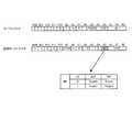
図2は、本実施形態のDRAMで用いられる主要なコマンドの種類を示す図である。図2の例では、本実施形態のDRAMに対し通常動作時に発行される代表的なコマンドとして、本実施形態に特有のDRFコマンドを含む8種のコマンドを示している。図2においては、各々のコマンドの機能に加え、制御信号の組合せパターンと、バンクアドレスBA0、BA0及びアドレスA0〜A12の状態が示されている。 FIG. 2 is a diagram showing the types of main commands used in the DRAM of this embodiment. In the example of FIG. 2, eight types of commands including DRF commands unique to the present embodiment are shown as typical commands issued during normal operation to the DRAM of the present embodiment. In FIG. 2, in addition to the function of each command, a combination pattern of control signals and states of bank addresses BA0 and BA0 and addresses A0 to A12 are shown.
なお、実際には図2に示すコマンドの種類に限られず、DRAMにおける各種機能を実行するための多様なコマンドが設定されている。また、通常動作時以外のデータ保持状態等で実行されるセルフリフレッシュやパワーダウンに関連するコマンドも設定されている。図2では、本実施形態の動作を理解するために有用なコマンドのみを示すものとする。 Actually, the commands are not limited to the types shown in FIG. 2, but various commands for executing various functions in the DRAM are set. Also, commands related to self-refresh and power-down executed in a data holding state other than during normal operation are set. In FIG. 2, only commands useful for understanding the operation of the present embodiment are shown.
図2において、ACTコマンドは、選択バンクにおいて指定された行アドレスをアクティブ状態にする。READコマンドは、選択バンクにおいてアクティブ状態の行アドレス及び指定された列アドレスからバーストリードを開始する。WRITコマンドは、選択バンクにおいてアクティブ状態の行アドレス及び指定された列アドレスからバーストライトを開始する。PREコマンドは、選択バンクに対するプリチャージ動作を実行する。なお、ACTコマンド、READコマンド、WRITコマンドでは、2ビットのバンクアドレスBA0、BA1により4つのバンク0〜3のいずれかが選択される。 In FIG. 2, the ACT command activates the row address specified in the selected bank. The READ command starts burst read from a row address in an active state and a designated column address in the selected bank. The WRIT command starts burst write from the row address and the designated column address in the active state in the selected bank. The PRE command executes a precharge operation for the selected bank. In the ACT command, READ command, and WRIT command, one of the four
本実施形態におけるオートリフレッシュ機能に関連してREFコマンドとDRFコマンドの2種が用意されている。REFコマンドは、本発明の通常オートリフレッシュコマンドに相当し、4つのバンク0〜3の全てに対するオートリフレッシュ動作の実行を要求する。DRFコマンドは、本発明のバンク選択リフレッシュコマンドに相当し、4つのバンク0〜3の中から任意の組合せで選択されたバンクのオートリフレッシュ動作(以下、ダイレクトオートリフレッシュと呼ぶ)の実行を要求する。このダイレクトオードリフレッシュは本実施形態に固有の機能であり、具体的な動作については後述する。これらのREFコマンド及びDRFコマンドは、それぞれ制御信号の組み合せパターンが共通のコマンドとして規定され、後述するように拡張モードレジスタの内容に応じて切り替え可能に設定されている。 Two types of REF command and DRF command are prepared in association with the auto-refresh function in this embodiment. The REF command corresponds to the normal auto-refresh command of the present invention, and requests execution of auto-refresh operation for all four
MRSコマンドは、図1のモードレジスタ202aに対し所望の設定情報をセットする。また、EMRSコマンドは、図1の拡張モードレジスタ202bに対し所望の設定情報をセットする。MRSコマンド又はEMRSコマンドを発行する場合、バンクアドレスBA0、BA1によって両者が区別されるとともに、アドレスA0〜A12を用いて設定情報が送出される。 The MRS command sets desired setting information in the
図3には、MRSコマンド及びEMRSコマンドによってセットされるモードレジスタ202a及び拡張モードレジスタ202bの構成例を示している。図3に示すように、MRSコマンドによってセットされるモードレジスタ202aには、例えば、/CASレーテンシ(LTMODE)、バースト長(BL)、バーストシーケンス(WT)などの設定情報などが格納される。また、EMRSコマンドによってセットされる拡張モードレジスタ202bには、例えば、自動温度補償セルフリフレッシュ(ATCSR)やパーシャルアレイセルフリフレッシュ(PASR)に加えて、本実施形態のオートリフレッシュ機能に関するDRFイネーブルDEが格納される。なお、DRFイネーブルDE以外の設定情報についての説明は省略する。 FIG. 3 shows a configuration example of the
図3に示すようにDRFイネーブルは、拡張モードレジスタ202bにおいてEMRSコマンドに含まれるアドレスA3のビット位置に割り当てられる。データイネーブルDRFが0か1かに応じて、オートリフレッシュ又はダイレクトオートリフレッシュの一方を設定することができる。すなわち、DRFイネーブルDEに0がセットされると(ディスエーブル)、REFコマンドが設定される。一方、DRFイネーブルDEに1がセットされると(イネーブル)、DRFコマンドが設定される。このように、EMRSコマンドを発行することにより、オートリフレッシュとダイレクトオートリフレッシュを選択的に設定することができる。 As shown in FIG. 3, the DRF enable is assigned to the bit position of the address A3 included in the EMRS command in the extended mode register 202b. One of auto refresh and direct auto refresh can be set according to whether the data enable DRF is 0 or 1. That is, when the DRF enable DE is set to 0 (disabled), the REF command is set. On the other hand, when 1 is set in the DRF enable DE (enable), the DRF command is set. Thus, by issuing the EMRS command, auto refresh and direct auto refresh can be selectively set.
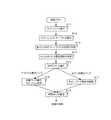
次に、本実施形態のダイレクトオートリフレッシュの動作について図4〜図6を参照しながら説明する。図4は、本実施形態のDRAMにおいてダイレクトオートリフレッシュを実行する場合の制御フローの具体例である。図5は、ダイレクトオートリフレッシュの実行時の動作波形の具体例である。図6は、DRFコマンドのバンク選択情報に基づくバンク選択の組合せを示す図である。 Next, the direct auto-refresh operation of this embodiment will be described with reference to FIGS. FIG. 4 is a specific example of a control flow when direct auto refresh is executed in the DRAM of this embodiment. FIG. 5 is a specific example of an operation waveform when the direct auto refresh is executed. FIG. 6 is a diagram showing a combination of bank selections based on bank selection information of the DRF command.
なお、図5においては、動作タイミングを規定するクロックCK、/CKを基準とし、外部コントローラにより発行されるコマンドと、バンクアドレス(BA:2ビットを重ねて表示)と、アドレス(ADD:アドレスの各ビットを重ねて表示)と、データ入出力タイミングを規定するデータストローブDQS0〜3と、リード動作時のデータ出力DQ(out)と、ライト動作のデータ入力DQ(in)についての動作波形を所定範囲の時間軸上で示している。 In FIG. 5, with reference to clocks CK and / CK that define the operation timing, a command issued by an external controller, a bank address (BA: displayed with 2 bits overlapped), an address (ADD: address The operation waveforms of the data strobes DQS0 to DQS0-3 for defining the data input / output timing, the data output DQ (out) during the read operation, and the data input DQ (in) for the write operation are predetermined. It is shown on the time axis of the range.
図4に示す制御フローの開始に先立って、予めEMRSコマンドによりDRFイネーブルに1がセットされ、ダイレクトオートリフレッシュが選択設定された状態にあるものとする。そして、通常動作時の所定のタイミングでバンク0〜3のいずれかを選択して、ライト動作又はリード動作を実行する(ステップS11)。図5の動作波形の例では、サイクルT0でバンク0に対してWRITコマンドが発行され、サイクルT2でバンク1に対してWRITコマンドが発行されている。これによりライト動作が実行され、4ビットずつ全部で8ビットのデータ入力in0〜in7がI/O回路23に取り込まれ、該当するアドレスに書き込まれる。 Prior to the start of the control flow shown in FIG. 4, it is assumed that the DRF enable is set to 1 in advance by the EMRS command and the direct auto refresh is selected and set. Then, one of the
次に図4において、予め設定されたリフレッシュインターバルに達したことを検知する(ステップS12)。一般にDRAMでは、メモリセルのリフレッシュを所定のリフレッシュ周期で行う必要があるが、リフレッシュカウンタ24により順次カウントされる行アドレスに対応するワード線ごとのリフレッシュは、それぞれのリフレッシュ周期内では分散したタイミングで順番に実行される。例えば、リフレッシュ周期が64msでワード線の本数が8192本であるとすると、64ms/8192=7.8μsのリフレッシュインターバルでリフレッシュ動作が実行されることになる。ステップS12では、前回のリフレッシュ動作のタイミングを起点に、リフレッシュインターバルが経過したタイミングを検知するものである。 Next, in FIG. 4, it is detected that a preset refresh interval has been reached (step S12). In general, in a DRAM, memory cells need to be refreshed at a predetermined refresh cycle, but refresh for each word line corresponding to row addresses sequentially counted by the
次いで、外部コントローラではリフレッシュ要求に先立って、各バンク0〜3がそれぞれビジー状態にあるか、又はアイドル状態にあるかを判別する(ステップS13)。すなわち、リード動作やライト動作の対象となったバンクは、一定の時間が経過するまでビジー状態を保つのでリフレッシュの対象として選択せず、それ以外のアイドル状態にあるバンクのみをリフレッシュの対象として選択するものである。外部コントローラは、直近のコマンド発行状況とそのタイミングに基づき、各バンク0〜3がビジー状態であるかアイドル状態であるかを判別することができる。 Next, prior to the refresh request, the external controller determines whether each of the
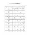
そして、ステップS13の判別結果に基づき、DRFコマンドに付加される4ビットのバンク選択情報を決定する(ステップS14)。図6に示すように、バンク選択情報はアドレスの下位4ビット(A3〜A0)に割り当てられ、A3〜A0を用いた16通り全てのビットパターンについて、リフレッシュ対象として選択されるバンク(Rを表記)の組合せが異なっている。例えば、4つのバンク0〜3の中から、1バンクを選択するパターン(4通り)、2バンクを選択するパターン(6通り)、3バンクを選択するパターン(4通り)、4バンク全てを選択するパターン(1通り)が含まれる。このように、4つのバンク0〜3がどのような組合せでビジー状態/アイドル状態になったとしても、アイドル状態のバンクのみをDRFコマンドのリフレッシュ対象として確実に選択可能となる。 Based on the determination result of step S13, 4-bit bank selection information to be added to the DRF command is determined (step S14). As shown in FIG. 6, the bank selection information is allocated to the lower 4 bits (A3 to A0) of the address, and the bank (R is indicated as a refresh target) for all 16 bit patterns using A3 to A0. ) Combination is different. For example, from 4
続いて、ステップS14のバンク選択情報を付加してDRFコマンドを発行する(ステップS15)。DRFコマンドの発行は、図2に示すように制御信号を組合せるとともに、アドレスの下位4ビットに所望のバンク選択情報をセットした状態で行われる。図5の例では、直近でバンク0及びバンク1のライト動作を実行しているので、バンク0、1がビジー状態、バンク2、3がアイドル状態となるので、バンク2、3をリフレッシュ対象とするために図6のC(H)がバンク選択情報としてセットされる。そして、サイクルT4において、アドレスの下位4ビットにC(H)をセットした状態で、DRFコマンドが発行されている。 Subsequently, the bank selection information of step S14 is added and a DRF command is issued (step S15). The DRF command is issued in a state where control signals are combined as shown in FIG. 2 and desired bank selection information is set in the lower 4 bits of the address. In the example of FIG. 5, since the
DRFコマンドがコマンドデコーダ201により判別されると、バンク制御部203の制御により、アイドル状態のバンクについて各々のリフレッシュカウンタ24のカウント値に応じたワード線のリフレッシュ動作が行われる(ステップS16)。一方、バンク制御部203の制御により、ビジー状態のバンクについてのリフレッシュ動作は行われず、それまでのライト動作とリード動作を中断することなく継続することができる(ステップS17)。 When the DRF command is determined by the
図5の例では、バンク2、3のリフレッシュ動作の実行中に、サイクルT6、T10でバンク0に対してREADコマンドが発行され、サイクルT8、12でバンク1に対してREADコマンドが発行されている。これによりリード動作が実行され、全部で16ビットのデータ出力o0〜o15がI/O回路23を介して外部に出力される。 In the example of FIG. 5, during the refresh operation of
次に、DRFコマンドの発行からリフレッシュ動作が完了するまでに必要な時間tRFCが経過したことを判断する(ステップS18)。リフレッシュ動作が完了したバンクに対しては、後続の処理を施すことができる。図5の例では、時間tRFCが15サイクル相当だけ確保され、その後のサイクルT19においてバンク3に対するACTコマンドが発行されている。以上のステップS11〜S18の処理は、リフレッシュインターバルが更新されるタイミングで毎回実行されることになる。 Next, it is determined that a time tRFC required from the issuance of the DRF command to the completion of the refresh operation has elapsed (step S18). Subsequent processing can be performed on the bank for which the refresh operation has been completed. In the example of FIG. 5, the time tRFC is secured for 15 cycles, and the ACT command for the
ここで、本実施形態のダイレクトオートリフレッシュの効果を旧来のオートリフレッシュと比較して説明するため、図7に旧来のオートリフレッシュを実行する場合の動作波形を比較例として示している。図7の比較例では、図5と同様、クロックCK、/CKとコマンド、バンクアドレス、データストローブDQS0〜3、データ出力DQ(out)、データ入力DQ(in)についての動作波形を示している。この場合は、予めEMRSコマンドによりDRFイネーブルが0にセットされ、旧来のオートリフレッシュが選択設定された状態にあるものとする。 Here, in order to explain the effect of the direct auto-refresh of the present embodiment in comparison with the conventional auto-refresh, FIG. 7 shows an operation waveform when executing the conventional auto-refresh as a comparative example. In the comparative example of FIG. 7, as in FIG. 5, operation waveforms for the clocks CK and / CK and the command, bank address, data strobes
図7において、サイクルT0でバンク0に対してWRITコマンドが発行されている。これにより、ライト動作が実行されてデータ入力in0〜in3が該当するアドレスに順次書き込まれる。このライト動作の途中のタイミングで、リフレッシュインターバルが到来する状況を考える。オートリフレッシュは4バンク同時に実行されるので、バンク0〜3の全てがアイドル状態であれば、直ちにリフレッシュ動作を実行することができる。しかし、図7の例では、バーストライトを実行中のバンク0はビジー状態にあるので、いったん書き込み対象データのライト動作の完了後、速やかにビジー状態からアイドル状態に移行させる必要がある。なお、図7において、ライト動作の代わりにリード動作を行う場合も同様である。 In FIG. 7, a WRIT command is issued to
そのため、最後のデータ入力in3の出力タイミングからライトリカバリー時間tWRが経過したサイクルT5でバンク0に対するPREコマンドが発行され、バンク0のプリチャージ動作が実行される。このとき、PREコマンドの発行タイミングからバンク0が実際にアイドル状態になるには時間tRPを要する。よって、図7では、時間tRPが経過したサイクルT9においてREFコマンドが発行され、4つのバンク0〜3のリフレッシュ動作が実行される。 Therefore, a PRE command for
REFコマンドの発行タイミングから、図5と同様の時間tRFCが経過すると4つのバンク0〜3のリフレッシュ動作が完了する。続いてバンク0のライト動作を再開すべく、時間tRFCが経過したサイクルT24においてバンク0に対するACTコマンドが発行される。このACTコマンドの発行タイミングから後続の動作を開始するには時間tRCDを要する。よって、図5では、時間tRCDが経過したサイクルT28においてバンク0に対するWRITコマンドが発行され、これによりバーストトライトを継続することになる。 When the same time tRFC as in FIG. 5 elapses from the issuing timing of the REF command, the refresh operations of the four
このように、ビジー状態のバンクが存在する状況でオートリフレッシュを実行するには、tWR+tRP+tRFC+tRCDだけの時間が必要となる。図7の比較例では、tWR=2サイクル、tRP=4サイクル、tRFC=15サイクル、tRCD=4サイクルであるから、トータルで25サイクルを要し、その分だけ他の処理に当てることができる時間を費やすことになる。これに対し、ダイレクトオートリフレッシュを実行する図5の例では、ビジー状態のバンクの動作を中断することなく、アイドル状態のバンクを対象として時間tRFCだけオートリフレッシュ動作を実行するが、完了するまでに要する15サイクルの時間内にはビジー状態のバンクに関する有効な処理を行うことができる。この場合は、ビジー状態のバンクについて不足するリフレッシュ回数を適宜のタイミングで実行すればよいので(詳しくは後述する)、動作効率を向上させることができる。 As described above, in order to execute auto-refresh in a situation where there is a busy bank, a time corresponding to tWR + tRP + tRFC + tRCD is required. In the comparative example of FIG. 7, since tWR = 2 cycles, tRP = 4 cycles, tRFC = 15 cycles, and tRCD = 4 cycles, a total of 25 cycles are required, and the time that can be used for other processing by that amount. Will be spent. On the other hand, in the example of FIG. 5 in which the direct auto-refresh is executed, the auto-refresh operation is executed for the idle bank for the time tRFC without interrupting the operation of the busy bank. Effective processing relating to a busy bank can be performed within the required time of 15 cycles. In this case, it is only necessary to execute an insufficient number of refreshes for a busy bank at an appropriate timing (details will be described later), so that the operation efficiency can be improved.
ここで、ダイレクトオートリフレッシュを採用する制御方法では、DRFコマンドの発行時点でビジー状態のバンクについてはリフレッシュ動作が実行されないが、少なくともリフレッシュ周期の要求は満たす必要がある。例えば、リフレッシュインターバル7.8μsごとのリフレッシュ動作が何度か実行されないとしても、リフレッシュ回数が不足しているバンクについて所定のタイミング及び不足回数分のリフレッシュ動作を実行すれば、リフレッシュ周期64msを超える事態にはならない。よって、以下の説明では、リフレッシュ回数が不足するバンクについて、所定のタイミングで必要な回数だけのリフレッシュ回数を充足する制御方法について説明する。 Here, in the control method employing the direct auto refresh, the refresh operation is not executed for the bank that is busy at the time of issuing the DRF command, but at least the refresh cycle requirement must be satisfied. For example, even if the refresh operation for every refresh interval 7.8 μs is not executed several times, if a refresh operation for a predetermined timing and the insufficient number of times is executed for a bank for which the number of refresh times is insufficient, the refresh cycle exceeds 64 ms. It will not be. Therefore, in the following description, a control method for satisfying the number of refreshes required at a predetermined timing for a bank in which the number of refreshes is insufficient will be described.
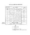
図8には、各々のバンクに対して不足リフレッシュ回数を充足する制御方法の具体例を示している。図8の例では、連続する8回のリフレッシュインターバルに続く9回目のリフレッシュインターバルを絶対最大インターバルと定義する。この絶対最大インターバルにおいては、予めビジー状態のバンクをプリチャージ動作によりアイドル状態に移行させた後に、それまでの8回のリフレッシュインターバルの間に各バンクのリフレッシュ回数が8回に満たない場合のリフレッシュ回数と、9回目のリフレッシュインターバルの1回とを併せた回数を不足リフレッシュ回数とみなし、各バンクでの不足リフレッシュ回数の最大値となる回数のリフレッシュ動作を実行するように制御を行う。 FIG. 8 shows a specific example of a control method for satisfying the insufficient refresh count for each bank. In the example of FIG. 8, the ninth refresh interval following the eight consecutive refresh intervals is defined as the absolute maximum interval. In this absolute maximum interval, after a busy bank is shifted to an idle state by a precharge operation in advance, refresh is performed when the number of refreshes of each bank is less than 8 during the previous 8 refresh intervals. The number of times combined with the number of times of the 9th refresh interval is regarded as the number of insufficient refreshes, and control is performed so that the refresh operation is performed for the number of times that is the maximum value of the number of insufficient refreshes in each bank.
例えば、図8に示すように、1回目のリフレッシュインターバルでは、バンク0がビジー状態、バンク1、2、3がアイドル状態であるから、バンク選択情報をE(H)に設定してDRFコマンドが発行される。以下、同様にバンク0〜3の状態に対応するバンク選択情報とともにDRFコマンドが発行される。そして、絶対最大インターバルに達すると、バンク0については8回のうちアイドル状態が5回、ビジー状態が3回含まれるので、これに9回目の分を加えた不足リフレッシュ回数は4回となる。一方、バンク1、2、3については8回のうちアイドル状態が6回、ビジー状態が2回含まれるので、いずれも不足リフレッシュ回数は2回となり、これに9回目の分を加えた不足リフレッシュ回数は3回となる。よって、不足リフレッシュ回数の最大値はバンク0の4回となり、絶対最大インターバルの9回目において、各バンクに対して4回連続してリフレッシュ動作を実行すればよい。 For example, as shown in FIG. 8, in the first refresh interval, since
不足リフレッシュ回数を充足するには、REFコマンドとDRFコマンドのいずれを用いてもよい。すなわち、REFコマンドを用いる場合は。EMRSコマンドにより拡張モードレジスタのDRFイネーブルDEに0をセットした上で、REFコマンドによりオートリフレッシュ動作を4回連続して実行すればよい。また、DRFコマンドを用いる場合、バンク選択情報を順に1(H)、F(H)、F(H)、F(H)と設定した状態でDRFコマンドによりオートリフレッシュ動作を4回連続して実行すればよい。なお、バンク選択情報として1(H)を設定する順は問わず、例えば、F(H)、F(H)、F(H)、1(H)の順にしてもよい。このような制御を行うことにより、絶対最大インターバルではリフレッシュ回数の要求を満たしつつ、9回目のリフレッシュ回数に至るまでビジー状態のバンクのリフレッシュを実行しなくて済むので、DRAMの動作効率を高めることができる。 To satisfy the insufficient refresh count, either the REF command or the DRF command may be used. That is, when using the REF command. The auto-refresh operation may be continuously executed four times by the REF command after setting the DRF enable DE of the extended mode register to 0 by the EMRS command. When using the DRF command, the auto refresh operation is continuously executed four times by the DRF command with the bank selection information set to 1 (H), F (H), F (H), and F (H) in order. do it. The order in which 1 (H) is set as the bank selection information is not limited. For example, F (H), F (H), F (H), and 1 (H) may be set in this order. By performing such control, it is not necessary to refresh the busy bank until the ninth refresh count is satisfied while satisfying the refresh count request in the absolute maximum interval, thereby improving the operation efficiency of the DRAM. Can do.
ここで、図8に示すようなDRFコマンドを用いる制御方法の効果を説明するための比較例として、図9に、旧来のREFコマンドのみを用いる制御方法を示している。図9の例では、連続する8回のリフレッシュインターバルにおける各バンクのビジー状態とアイドル状態が図8と同様に変化する場合を示している。図9では、オートリフレッシュの実行時に、図7の例のようにビジー状態のバンクをアイドル状態に移行させる制御を行わないことを前提とする。この場合、ビジー状態のバンクが1つでもあるとREFコマンドが発行されないため、8回のリフレッシュインターバルのうち、全バンクがアイドル状態となる5回目のリフレッシュインターバルでのみREFコマンドに基づくリフレッシュ動作が実行される。それ以外のリフレッシュインターバルは、不足リフレッシュ回数となるので、9回目の絶対最大インターバルにおいて併せて8回のリフレッシュ動作を連続して実行する必要がある。よって、同様の条件で絶対最大インターバルにおけるリフレッシュ回数が4回で済む本実施形態のダイレクトオートリフレッシュは、良好な動作効率を確保することができる。 Here, as a comparative example for explaining the effect of the control method using the DRF command as shown in FIG. 8, FIG. 9 shows a control method using only the conventional REF command. The example of FIG. 9 shows a case where the busy state and the idle state of each bank change in the same manner as in FIG. 8 in eight consecutive refresh intervals. FIG. 9 is based on the premise that control for shifting a busy bank to an idle state as in the example of FIG. 7 is not performed during execution of auto-refresh. In this case, since the REF command is not issued if there is even one busy bank, the refresh operation based on the REF command is executed only during the fifth refresh interval in which all banks are in the idle state among the eight refresh intervals. Is done. Since the refresh interval other than that is the number of insufficient refreshes, it is necessary to continuously execute 8 refresh operations in addition to the 9th absolute maximum interval. Therefore, the direct auto-refresh of the present embodiment that requires only four refreshes in the absolute maximum interval under the same conditions can ensure good operating efficiency.
上記の図8に示す制御方法では、周期的に絶対最大インターバルにおいて不足リフレッシュ回数を充足する場合を説明したが、かかる制御方法について変形例がある。具体的には、外部のコントローラが毎回のリフレッシュインターバルにおいて、DRFコマンドを用いて各バンクのビジー状態/アイドル状態に応じて実行されるリフレッシュ動作のうちの未実行回数をバンクごとにカウントし、特定のバンクで未実行回数が規定数に達したときに、図8の絶対最大インターバルの場合と同様の制御を行う。例えば、特定のバンクで未実行回数が8回に達したとき、その次のリフレッシュインターバルで9回連続してリフレッシュ動作を実行する。このような変形例を採用する場合、最大8回のリフレッシュインターバル相当の時間(62.5μs)だけリフレッシュ動作が遅延する可能性があるが、これはリフレッシュ周期の64msと比べて十分短く(約0.1%)誤差の範囲であり、データ保持特性には影響を与えることはない。 In the control method shown in FIG. 8 described above, the case has been described in which the number of insufficient refreshes is periodically satisfied in the absolute maximum interval. However, there is a modification of the control method. Specifically, the external controller counts the number of unexecuted refresh operations performed for each bank in response to the busy / idle state of each bank using the DRF command at each refresh interval. When the number of unexecuted times reaches the specified number in the bank, the same control as in the case of the absolute maximum interval in FIG. 8 is performed. For example, when the number of unexecuted times reaches 8 in a specific bank, the refresh operation is continuously executed 9 times in the next refresh interval. When such a modification is adopted, the refresh operation may be delayed by a time corresponding to a maximum of 8 refresh intervals (62.5 μs), which is sufficiently shorter than the refresh cycle of 64 ms (about 0). .1%) error range and does not affect data retention characteristics.
以上、本実施形態に基づき本発明について具体的に説明したが、本発明は上述の実施形態に限定されるものではなく、その要旨を逸脱しない範囲で種々の変更を施すことができる。例えば、本実施形態では4バンク構成のDRAMに対して本発明を適用する場合を説明したが、Nバンク構成のバンクに対しても本発明を適用することができる。この場合、Nバンクの選択の有無を含む2N通りの組合せでバンク選択情報を設定する必要がある。また例えば、本実施形態ではDRFコマンドとREFコマンドを選択的に利用可能とする場合を説明したが、DRFコマンドのみを利用可能としてもよい。この場合、図6のバンク選択情報にF(H)を設定することにより、旧来のREFコマンドを置き換えることができる。また、本実施形態ではDRFコマンドとREFコマンドを選択する場合、拡張モードレジスタのDRFイネーブルDEを設定する場合を説明したが、図2において異なる制御信号の組み合わせでDRFコマンドとREFコマンドを別々に規定してもよい。As mentioned above, although this invention was concretely demonstrated based on this embodiment, this invention is not limited to the above-mentioned embodiment, A various change can be given in the range which does not deviate from the summary. For example, in the present embodiment, the case where the present invention is applied to a DRAM having a 4-bank configuration has been described, but the present invention can also be applied to a bank having an N-bank configuration. In this case, it is necessary to set the bank selection information in2N combinations including whether or not N banks are selected. For example, in the present embodiment, the case where the DRF command and the REF command can be selectively used has been described, but only the DRF command may be used. In this case, the old REF command can be replaced by setting F (H) in the bank selection information of FIG. Further, in this embodiment, the case where the DRF command and the REF command are selected, and the case where the DRF enable DE of the extended mode register is set has been described. However, in FIG. May be.
また、本実施形態では、半導体メモリとしてのDRAMに対して本発明を適用する場合を説明したが、DRAM以外の他の半導体メモリに対しても本発明を適用することができる。さらに、半導体メモリを含むメモリシステムを構築する場合であっても本発明を適用することができる。 In this embodiment, the case where the present invention is applied to a DRAM as a semiconductor memory has been described. However, the present invention can also be applied to a semiconductor memory other than a DRAM. Furthermore, the present invention can be applied even when a memory system including a semiconductor memory is constructed.
10…メモリアレイ(バンク0〜3)
11…行系回路
12…行アドレスラッチ
13…列系回路
20…制御回路
21…アドレスレジスタ
22…列アドレスラッチ
23…I/O回路
24…リフレッシュカウンタ
25…アドレスセレクタ
201…コマンドデコーダ
202a…モードレジスタ
202b…拡張モードレジスタ
203…バンク制御部
10 ... Memory array (
DESCRIPTION OF
Claims (11)
Translated fromJapanese前記複数のバンクの各々に設けられ、リフレッシュ対象の行アドレスを発生するリフレッシュアドレス発生回路と、
前記複数のバンクの中から任意の組合せで選択されたバンクを示すバンク選択情報が付加されたリフレッシュ要求に応じて、前記バンク選択情報に基づき選択されたバンクに対する前記リフレッシュ動作を実行する一方、前記バンク選択情報に基づき選択されないバンクに対する前記リフレッシュ動作を実行しないように制御する制御回路と、
を備えることを特徴とする半導体メモリ装置。A semiconductor memory device comprising a memory array divided into a plurality of independently controllable banks and executing a refresh operation on the memory array,
A refresh address generating circuit that is provided in each of the plurality of banks and generates a row address to be refreshed;
In response to a refresh request to which bank selection information indicating a bank selected in an arbitrary combination from among the plurality of banks is added, the refresh operation is performed on the bank selected based on the bank selection information. A control circuit that controls not to perform the refresh operation for a bank that is not selected based on the bank selection information;
A semiconductor memory device comprising:
前記バンク選択情報に基づき選択されたバンクに対応する前記リフレッシュアドレス発生回路は、前記リフレッシュインターバルごとに前記リフレッシュ対象の行アドレスを更新することを特徴とする請求項1から3のいずれかに記載の半導体メモリ装置。The refresh operation is an auto-refresh operation that is sequentially executed at a predetermined refresh interval during normal operation,
4. The refresh address generation circuit corresponding to a bank selected based on the bank selection information updates the row address to be refreshed at each refresh interval. Semiconductor memory device.
前記制御回路は、前記バンク選択オートリフレッシュコマンドと前記通常オートリフレッシュコマンドを判別し、要求された前記オートリフレッシュ動作を実行制御することを特徴とする請求項4に記載の半導体メモリ装置。As two types of commands for requesting the auto-refresh operation, a bank selection auto-refresh command for requesting an auto-refresh operation for a bank selected by the bank selection information and a normal auto-refresh command for requesting an auto-refresh operation for all banks. Is defined,
5. The semiconductor memory device according to claim 4, wherein the control circuit determines the bank selection auto-refresh command and the normal auto-refresh command, and executes and controls the requested auto-refresh operation.
前記制御回路は、前記バンク選択オートリフレッシュと前記通常オートリフレッシュを切り替え可能に設定する設定情報をモードレジスタに保持し、前記共通のオートリフレッシュコマンドが発行されたとき、前記モードレジスタに保持される前記設定情報に基づいて前記バンク選択オートリフレッシュコマンドと前記通常オートリフレッシュコマンドのいずれであるかを判別することを特徴とする請求項5に記載の半導体メモリ装置。A common auto refresh command is defined for the bank selection auto refresh command and the normal auto refresh,
The control circuit holds setting information for setting the bank selection auto-refresh and the normal auto-refresh to be switchable in a mode register, and is held in the mode register when the common auto-refresh command is issued. 6. The semiconductor memory device according to claim 5, wherein it is determined whether the bank selection auto-refresh command or the normal auto-refresh command is based on setting information.
前記リフレッシュ動作を行う所定のタイミングで、前記複数のバンクの各々がビジー状態であるか否かを判断し、ビジー状態ではないバンクのみを示すバンク選択情報を決定し、当該決定されたバンク選択情報を付加してリフレッシュ要求を行い、
前記リフレッシュ要求を受けた前記半導体メモリ装置において、前記バンク選択情報に基づき選択されたバンクに対する前記リフレッシュ動作を実行する一方、前記バンク選択情報に基づき選択されないバンクに対する前記リフレッシュ動作を実行しないように制御する、
ことを特徴とするメモリシステムのリフレッシュ制御方法。A refresh control method for a memory system comprising a semiconductor memory device comprising a memory array divided into a plurality of independently controllable banks and executing and controlling a refresh operation for a bank selected from the plurality of banks. ,
At a predetermined timing for performing the refresh operation, it is determined whether each of the plurality of banks is busy, bank selection information indicating only banks that are not busy is determined, and the determined bank selection information To make a refresh request,
In the semiconductor memory device that has received the refresh request, the refresh operation is performed on the bank selected based on the bank selection information, while the refresh operation is not performed on a bank that is not selected based on the bank selection information. To
A refresh control method for a memory system.
When the number of executions of the auto-refresh operation executed for each bank in response to the selected auto-refresh command is insufficient for the predetermined number for each period including the predetermined number of refresh intervals, at least the number of shortages for each bank is satisfied. 11. The refresh control method for a memory system according to claim 10, wherein the execution control of the auto-refresh operation is performed a number of times.
Priority Applications (4)
| Application Number | Priority Date | Filing Date | Title |
|---|---|---|---|
| JP2005216429AJP2007035151A (en) | 2005-07-26 | 2005-07-26 | Semiconductor memory device and refresh control method of memory system |
| US11/996,694US20100128547A1 (en) | 2005-07-26 | 2006-07-19 | Semiconductor memory device and refresh control method of memory system |
| PCT/JP2006/314304WO2007013340A1 (en) | 2005-07-26 | 2006-07-19 | Semiconductor memory device and memory system refresh control method |
| US12/946,507US20110058438A1 (en) | 2005-07-26 | 2010-11-15 | Semiconductor memory device and refresh control method of memory system |
Applications Claiming Priority (1)
| Application Number | Priority Date | Filing Date | Title |
|---|---|---|---|
| JP2005216429AJP2007035151A (en) | 2005-07-26 | 2005-07-26 | Semiconductor memory device and refresh control method of memory system |
Publications (1)
| Publication Number | Publication Date |
|---|---|
| JP2007035151Atrue JP2007035151A (en) | 2007-02-08 |
Family
ID=37683241
Family Applications (1)
| Application Number | Title | Priority Date | Filing Date |
|---|---|---|---|
| JP2005216429APendingJP2007035151A (en) | 2005-07-26 | 2005-07-26 | Semiconductor memory device and refresh control method of memory system |
Country Status (3)
| Country | Link |
|---|---|
| US (2) | US20100128547A1 (en) |
| JP (1) | JP2007035151A (en) |
| WO (1) | WO2007013340A1 (en) |
Cited By (1)
| Publication number | Priority date | Publication date | Assignee | Title |
|---|---|---|---|---|
| WO2011084499A3 (en)* | 2009-12-16 | 2011-10-13 | Micron Technology, Inc. | Techniques for reducing impact of array disturbs in a semiconductor memory device |
Families Citing this family (25)
| Publication number | Priority date | Publication date | Assignee | Title |
|---|---|---|---|---|
| US8327057B1 (en)* | 2007-04-16 | 2012-12-04 | Juniper Networks, Inc. | Ordering write bursts to memory |
| US8489807B2 (en) | 2010-12-03 | 2013-07-16 | International Business Machines Corporation | Techniques for performing refresh operations in high-density memories |
| US9036439B2 (en)* | 2011-07-15 | 2015-05-19 | Samsung Electronics Co., Ltd. | Semiconductor memory device having improved refresh characteristics |
| US8539146B2 (en) | 2011-11-28 | 2013-09-17 | International Business Machines Corporation | Apparatus for scheduling memory refresh operations including power states |
| US10490251B2 (en) | 2017-01-30 | 2019-11-26 | Micron Technology, Inc. | Apparatuses and methods for distributing row hammer refresh events across a memory device |
| US10878879B2 (en)* | 2017-06-21 | 2020-12-29 | Mediatek Inc. | Refresh control method for memory system to perform refresh action on all memory banks of the memory system within refresh window |
| CN112106138B (en) | 2018-05-24 | 2024-02-27 | 美光科技公司 | Apparatus and method for pure time adaptive sampling for row hammer refresh sampling |
| KR102544184B1 (en)* | 2018-08-09 | 2023-06-16 | 에스케이하이닉스 주식회사 | Semiconductor memory apparatus and refresh method thereof |
| US10685696B2 (en) | 2018-10-31 | 2020-06-16 | Micron Technology, Inc. | Apparatuses and methods for access based refresh timing |
| CN113168861B (en) | 2018-12-03 | 2024-05-14 | 美光科技公司 | Semiconductor device performing row hammer refresh operation |
| CN117198356A (en) | 2018-12-21 | 2023-12-08 | 美光科技公司 | Apparatus and method for timing interleaving for targeted refresh operations |
| US10957377B2 (en) | 2018-12-26 | 2021-03-23 | Micron Technology, Inc. | Apparatuses and methods for distributed targeted refresh operations |
| US11615831B2 (en) | 2019-02-26 | 2023-03-28 | Micron Technology, Inc. | Apparatuses and methods for memory mat refresh sequencing |
| US11227649B2 (en) | 2019-04-04 | 2022-01-18 | Micron Technology, Inc. | Apparatuses and methods for staggered timing of targeted refresh operations |
| US11069393B2 (en) | 2019-06-04 | 2021-07-20 | Micron Technology, Inc. | Apparatuses and methods for controlling steal rates |
| US10978132B2 (en) | 2019-06-05 | 2021-04-13 | Micron Technology, Inc. | Apparatuses and methods for staggered timing of skipped refresh operations |
| US11302374B2 (en) | 2019-08-23 | 2022-04-12 | Micron Technology, Inc. | Apparatuses and methods for dynamic refresh allocation |
| US11302377B2 (en) | 2019-10-16 | 2022-04-12 | Micron Technology, Inc. | Apparatuses and methods for dynamic targeted refresh steals |
| US11309010B2 (en) | 2020-08-14 | 2022-04-19 | Micron Technology, Inc. | Apparatuses, systems, and methods for memory directed access pause |
| US11348631B2 (en) | 2020-08-19 | 2022-05-31 | Micron Technology, Inc. | Apparatuses, systems, and methods for identifying victim rows in a memory device which cannot be simultaneously refreshed |
| US11380382B2 (en) | 2020-08-19 | 2022-07-05 | Micron Technology, Inc. | Refresh logic circuit layout having aggressor detector circuit sampling circuit and row hammer refresh control circuit |
| US11557331B2 (en) | 2020-09-23 | 2023-01-17 | Micron Technology, Inc. | Apparatuses and methods for controlling refresh operations |
| US11264079B1 (en) | 2020-12-18 | 2022-03-01 | Micron Technology, Inc. | Apparatuses and methods for row hammer based cache lockdown |
| US12112787B2 (en) | 2022-04-28 | 2024-10-08 | Micron Technology, Inc. | Apparatuses and methods for access based targeted refresh operations |
| US12125514B2 (en) | 2022-04-28 | 2024-10-22 | Micron Technology, Inc. | Apparatuses and methods for access based refresh operations |
Citations (13)
| Publication number | Priority date | Publication date | Assignee | Title |
|---|---|---|---|---|
| JPS6212990A (en)* | 1985-07-09 | 1987-01-21 | Fujitsu Ltd | Dynamic type semiconductor storage device |
| JPH01227299A (en)* | 1988-03-08 | 1989-09-11 | Fujitsu Ltd | Memory refresh control method |
| JPH04149892A (en)* | 1990-10-11 | 1992-05-22 | Fujitsu Ltd | Memory control method |
| JPH05151772A (en)* | 1991-11-29 | 1993-06-18 | Nec Corp | Refresh control circuit |
| JPH09139074A (en)* | 1995-11-10 | 1997-05-27 | Hitachi Ltd | Dynamic RAM |
| JPH10134569A (en)* | 1996-10-24 | 1998-05-22 | Toshiba Corp | Synchronous dynamic random access memory |
| JP2000251467A (en)* | 1999-03-02 | 2000-09-14 | Nec Ibaraki Ltd | Memory refresh controller and control method therefor |
| JP2001093277A (en)* | 1999-09-22 | 2001-04-06 | Fujitsu Ltd | Semiconductor integrated circuit and control method thereof |
| JP2002133860A (en)* | 2000-10-20 | 2002-05-10 | Seiko Epson Corp | Semiconductor device, refresh method therefor, memory system and electronic device |
| JP2003030983A (en)* | 2001-07-13 | 2003-01-31 | Mitsubishi Electric Corp | Dynamic semiconductor memory device |
| JP2004152420A (en)* | 2002-10-31 | 2004-05-27 | Toshiba Corp | Semiconductor device |
| JP2004265503A (en)* | 2003-02-28 | 2004-09-24 | Seiko Epson Corp | Semiconductor integrated circuit |
| JP2005174437A (en)* | 2003-12-10 | 2005-06-30 | Sony Corp | Refreshing system of storage device |
Family Cites Families (14)
| Publication number | Priority date | Publication date | Assignee | Title |
|---|---|---|---|---|
| JPH09306165A (en)* | 1996-05-16 | 1997-11-28 | Hitachi Commun Syst Inc | DRAM refresh control circuit |
| JPH09312094A (en)* | 1996-05-23 | 1997-12-02 | Nec Eng Ltd | Refresh control system |
| CN1137491C (en)* | 1998-03-30 | 2004-02-04 | 西门子公司 | Decoding Automatic Refresh Mode in DRAM |
| JP2000021162A (en)* | 1998-07-03 | 2000-01-21 | Mitsubishi Electric Corp | Volatile memory and embedded dynamic random access memory |
| KR100355226B1 (en)* | 1999-01-12 | 2002-10-11 | 삼성전자 주식회사 | DRAM performable selectively self-refresh operation for memory bank |
| US20020194444A1 (en)* | 2001-06-14 | 2002-12-19 | Telgen Corporation | System and method for managing out-of-order memory access requests via an age-shifted index |
| US6552955B1 (en)* | 2001-10-30 | 2003-04-22 | Mitsubishi Denki Kabushiki Kaisha | Semiconductor memory device with reduced power consumption |
| JP2003338175A (en)* | 2002-05-20 | 2003-11-28 | Mitsubishi Electric Corp | Semiconductor circuit device |
| US6912168B2 (en)* | 2003-03-18 | 2005-06-28 | United Memories, Inc. | Non-contiguous masked refresh for an integrated circuit memory |
| US6954387B2 (en)* | 2003-07-15 | 2005-10-11 | International Business Machines Corporation | Dynamic random access memory with smart refresh scheduler |
| US20050108460A1 (en)* | 2003-11-14 | 2005-05-19 | Intel Corporation | Partial bank DRAM refresh |
| US20050268022A1 (en)* | 2004-05-26 | 2005-12-01 | Pelley Perry H | Cache line memory and method therefor |
| KR100608370B1 (en)* | 2004-11-15 | 2006-08-08 | 주식회사 하이닉스반도체 | How to perform a refresh of a memory device |
| US7757061B2 (en)* | 2005-05-03 | 2010-07-13 | Micron Technology, Inc. | System and method for decoding commands based on command signals and operating state |
- 2005
- 2005-07-26JPJP2005216429Apatent/JP2007035151A/enactivePending
- 2006
- 2006-07-19USUS11/996,694patent/US20100128547A1/ennot_activeAbandoned
- 2006-07-19WOPCT/JP2006/314304patent/WO2007013340A1/enactiveApplication Filing
- 2010
- 2010-11-15USUS12/946,507patent/US20110058438A1/ennot_activeAbandoned
Patent Citations (13)
| Publication number | Priority date | Publication date | Assignee | Title |
|---|---|---|---|---|
| JPS6212990A (en)* | 1985-07-09 | 1987-01-21 | Fujitsu Ltd | Dynamic type semiconductor storage device |
| JPH01227299A (en)* | 1988-03-08 | 1989-09-11 | Fujitsu Ltd | Memory refresh control method |
| JPH04149892A (en)* | 1990-10-11 | 1992-05-22 | Fujitsu Ltd | Memory control method |
| JPH05151772A (en)* | 1991-11-29 | 1993-06-18 | Nec Corp | Refresh control circuit |
| JPH09139074A (en)* | 1995-11-10 | 1997-05-27 | Hitachi Ltd | Dynamic RAM |
| JPH10134569A (en)* | 1996-10-24 | 1998-05-22 | Toshiba Corp | Synchronous dynamic random access memory |
| JP2000251467A (en)* | 1999-03-02 | 2000-09-14 | Nec Ibaraki Ltd | Memory refresh controller and control method therefor |
| JP2001093277A (en)* | 1999-09-22 | 2001-04-06 | Fujitsu Ltd | Semiconductor integrated circuit and control method thereof |
| JP2002133860A (en)* | 2000-10-20 | 2002-05-10 | Seiko Epson Corp | Semiconductor device, refresh method therefor, memory system and electronic device |
| JP2003030983A (en)* | 2001-07-13 | 2003-01-31 | Mitsubishi Electric Corp | Dynamic semiconductor memory device |
| JP2004152420A (en)* | 2002-10-31 | 2004-05-27 | Toshiba Corp | Semiconductor device |
| JP2004265503A (en)* | 2003-02-28 | 2004-09-24 | Seiko Epson Corp | Semiconductor integrated circuit |
| JP2005174437A (en)* | 2003-12-10 | 2005-06-30 | Sony Corp | Refreshing system of storage device |
Cited By (4)
| Publication number | Priority date | Publication date | Assignee | Title |
|---|---|---|---|---|
| WO2011084499A3 (en)* | 2009-12-16 | 2011-10-13 | Micron Technology, Inc. | Techniques for reducing impact of array disturbs in a semiconductor memory device |
| CN102656638A (en)* | 2009-12-16 | 2012-09-05 | 美光科技公司 | Techniques for reducing impact of array disturbs in a semiconductor memory device |
| US8310893B2 (en) | 2009-12-16 | 2012-11-13 | Micron Technology, Inc. | Techniques for reducing impact of array disturbs in a semiconductor memory device |
| CN102656638B (en)* | 2009-12-16 | 2015-08-19 | 美光科技公司 | For reducing the technology of the impact of array interference in semiconductor memory system |
Also Published As
| Publication number | Publication date |
|---|---|
| US20110058438A1 (en) | 2011-03-10 |
| WO2007013340A1 (en) | 2007-02-01 |
| US20100128547A1 (en) | 2010-05-27 |
Similar Documents
| Publication | Publication Date | Title |
|---|---|---|
| JP2007035151A (en) | Semiconductor memory device and refresh control method of memory system | |
| US11935576B2 (en) | Semiconductor device performing row hammer refresh operation | |
| JP4609813B2 (en) | Semiconductor device | |
| KR100877651B1 (en) | Semiconductor memory | |
| JP4843655B2 (en) | Semiconductor memory device | |
| US5999472A (en) | Multi-bank synchronous semiconductor memory device with easy control | |
| EP2284838B1 (en) | Semiconductor memory, memory controller, system, and operating method of semiconductor memory | |
| KR19990078379A (en) | Decoded autorefresh mode in a dram | |
| EP1751768B1 (en) | Method and system for controlling refresh in volatile memories | |
| JP2008090904A (en) | Semiconductor memory device and memory system | |
| US7894290B2 (en) | Method and apparatus for performing internal hidden refreshes while latching read/write commands, address and data information for later operation | |
| US20110007592A1 (en) | Semiconductor storage device and refresh control method thereof | |
| JP2007087375A (en) | Memory control system and memory control circuit | |
| JP4362573B2 (en) | memory | |
| US6108265A (en) | Semiconductor memory | |
| JP4419071B2 (en) | Semiconductor memory refresh control method and semiconductor memory device | |
| TWI891296B (en) | Semiconductor memory device and method for controlling the same | |
| JP4561089B2 (en) | Storage device | |
| US7061818B2 (en) | Memory and refresh method for memory | |
| JP4753637B2 (en) | memory | |
| JPH11306753A (en) | Semiconductor storage | |
| JP2005174437A5 (en) | ||
| JPH0478093A (en) | Memory controller | |
| HK1101447A (en) | Method and system for controlling refresh in volatile memories | |
| KR20010064322A (en) | Method for generating automated column address in SDRAM |
Legal Events
| Date | Code | Title | Description |
|---|---|---|---|
| A621 | Written request for application examination | Free format text:JAPANESE INTERMEDIATE CODE: A621 Effective date:20070308 | |
| RD05 | Notification of revocation of power of attorney | Free format text:JAPANESE INTERMEDIATE CODE: A7425 Effective date:20071119 | |
| A131 | Notification of reasons for refusal | Free format text:JAPANESE INTERMEDIATE CODE: A131 Effective date:20091110 | |
| A521 | Written amendment | Free format text:JAPANESE INTERMEDIATE CODE: A523 Effective date:20100108 | |
| A131 | Notification of reasons for refusal | Free format text:JAPANESE INTERMEDIATE CODE: A131 Effective date:20101026 | |
| A521 | Written amendment | Free format text:JAPANESE INTERMEDIATE CODE: A523 Effective date:20101224 | |
| A02 | Decision of refusal | Free format text:JAPANESE INTERMEDIATE CODE: A02 Effective date:20110823 |