JP2007030882A - Truck - Google Patents
TruckDownload PDFInfo
- Publication number
- JP2007030882A JP2007030882AJP2006307660AJP2006307660AJP2007030882AJP 2007030882 AJP2007030882 AJP 2007030882AJP 2006307660 AJP2006307660 AJP 2006307660AJP 2006307660 AJP2006307660 AJP 2006307660AJP 2007030882 AJP2007030882 AJP 2007030882A
- Authority
- JP
- Japan
- Prior art keywords
- wheel
- wheels
- fixed
- turning
- central
- Prior art date
- Legal status (The legal status is an assumption and is not a legal conclusion. Google has not performed a legal analysis and makes no representation as to the accuracy of the status listed.)
- Pending
Links
- 239000007787solidSubstances0.000claimsabstractdescription13
- 240000004282Grewia occidentalisSpecies0.000abstract2
- 229910000831SteelInorganic materials0.000description7
- 239000010959steelSubstances0.000description7
- 230000000694effectsEffects0.000description6
- 239000000463materialSubstances0.000description4
- 238000003466weldingMethods0.000description4
- 230000004048modificationEffects0.000description3
- 238000012986modificationMethods0.000description3
- 230000000116mitigating effectEffects0.000description2
- 230000035939shockEffects0.000description1
- 239000000725suspensionSubstances0.000description1
Images


Classifications
- B—PERFORMING OPERATIONS; TRANSPORTING
- B60—VEHICLES IN GENERAL
- B60B—VEHICLE WHEELS; CASTORS; AXLES FOR WHEELS OR CASTORS; INCREASING WHEEL ADHESION
- B60B33/00—Castors in general; Anti-clogging castors
- B60B33/04—Castors in general; Anti-clogging castors adjustable, e.g. in height; linearly shifting castors
- B60B33/045—Castors in general; Anti-clogging castors adjustable, e.g. in height; linearly shifting castors mounted resiliently, by means of dampers
- B—PERFORMING OPERATIONS; TRANSPORTING
- B60—VEHICLES IN GENERAL
- B60B—VEHICLE WHEELS; CASTORS; AXLES FOR WHEELS OR CASTORS; INCREASING WHEEL ADHESION
- B60B33/00—Castors in general; Anti-clogging castors
- B60B33/0036—Castors in general; Anti-clogging castors characterised by type of wheels
- B60B33/0039—Single wheels
- B—PERFORMING OPERATIONS; TRANSPORTING
- B60—VEHICLES IN GENERAL
- B60B—VEHICLE WHEELS; CASTORS; AXLES FOR WHEELS OR CASTORS; INCREASING WHEEL ADHESION
- B60B33/00—Castors in general; Anti-clogging castors
- B60B33/0036—Castors in general; Anti-clogging castors characterised by type of wheels
- B60B33/0042—Double or twin wheels
- B—PERFORMING OPERATIONS; TRANSPORTING
- B60—VEHICLES IN GENERAL
- B60B—VEHICLE WHEELS; CASTORS; AXLES FOR WHEELS OR CASTORS; INCREASING WHEEL ADHESION
- B60B33/00—Castors in general; Anti-clogging castors
- B60B33/0047—Castors in general; Anti-clogging castors characterised by details of the rolling axle
- B60B33/0049—Castors in general; Anti-clogging castors characterised by details of the rolling axle the rolling axle being horizontal
- B—PERFORMING OPERATIONS; TRANSPORTING
- B60—VEHICLES IN GENERAL
- B60B—VEHICLE WHEELS; CASTORS; AXLES FOR WHEELS OR CASTORS; INCREASING WHEEL ADHESION
- B60B33/00—Castors in general; Anti-clogging castors
- B60B33/0047—Castors in general; Anti-clogging castors characterised by details of the rolling axle
- B60B33/0057—Castors in general; Anti-clogging castors characterised by details of the rolling axle the rolling axle being offset from swivel axis
- B—PERFORMING OPERATIONS; TRANSPORTING
- B60—VEHICLES IN GENERAL
- B60B—VEHICLE WHEELS; CASTORS; AXLES FOR WHEELS OR CASTORS; INCREASING WHEEL ADHESION
- B60B33/00—Castors in general; Anti-clogging castors
- B60B33/006—Castors in general; Anti-clogging castors characterised by details of the swivel mechanism
- B60B33/0063—Castors in general; Anti-clogging castors characterised by details of the swivel mechanism no swivelling action, i.e. no real caster
- B—PERFORMING OPERATIONS; TRANSPORTING
- B60—VEHICLES IN GENERAL
- B60B—VEHICLE WHEELS; CASTORS; AXLES FOR WHEELS OR CASTORS; INCREASING WHEEL ADHESION
- B60B33/00—Castors in general; Anti-clogging castors
- B60B33/006—Castors in general; Anti-clogging castors characterised by details of the swivel mechanism
- B60B33/0065—Castors in general; Anti-clogging castors characterised by details of the swivel mechanism characterised by details of the swivel axis
- B60B33/0068—Castors in general; Anti-clogging castors characterised by details of the swivel mechanism characterised by details of the swivel axis the swivel axis being vertical
- B—PERFORMING OPERATIONS; TRANSPORTING
- B60—VEHICLES IN GENERAL
- B60B—VEHICLE WHEELS; CASTORS; AXLES FOR WHEELS OR CASTORS; INCREASING WHEEL ADHESION
- B60B33/00—Castors in general; Anti-clogging castors
- B60B33/006—Castors in general; Anti-clogging castors characterised by details of the swivel mechanism
- B60B33/0065—Castors in general; Anti-clogging castors characterised by details of the swivel mechanism characterised by details of the swivel axis
- B60B33/0073—Castors in general; Anti-clogging castors characterised by details of the swivel mechanism characterised by details of the swivel axis the swivel axis being symmetrical to wheel or wheels
- B—PERFORMING OPERATIONS; TRANSPORTING
- B62—LAND VEHICLES FOR TRAVELLING OTHERWISE THAN ON RAILS
- B62B—HAND-PROPELLED VEHICLES, e.g. HAND CARTS OR PERAMBULATORS; SLEDGES
- B62B3/00—Hand carts having more than one axis carrying transport wheels; Steering devices therefor; Equipment therefor
- B62B3/001—Steering devices
- B—PERFORMING OPERATIONS; TRANSPORTING
- B62—LAND VEHICLES FOR TRAVELLING OTHERWISE THAN ON RAILS
- B62D—MOTOR VEHICLES; TRAILERS
- B62D53/00—Tractor-trailer combinations; Road trains
- B62D53/005—Combinations with at least three axles and comprising two or more articulated parts
- B—PERFORMING OPERATIONS; TRANSPORTING
- B62—LAND VEHICLES FOR TRAVELLING OTHERWISE THAN ON RAILS
- B62D—MOTOR VEHICLES; TRAILERS
- B62D61/00—Motor vehicles or trailers, characterised by the arrangement or number of wheels, not otherwise provided for, e.g. four wheels in diamond pattern
- B62D61/10—Motor vehicles or trailers, characterised by the arrangement or number of wheels, not otherwise provided for, e.g. four wheels in diamond pattern with more than four wheels
- B—PERFORMING OPERATIONS; TRANSPORTING
- B62—LAND VEHICLES FOR TRAVELLING OTHERWISE THAN ON RAILS
- B62B—HAND-PROPELLED VEHICLES, e.g. HAND CARTS OR PERAMBULATORS; SLEDGES
- B62B2207/00—Joining hand-propelled vehicles or sledges together
- B—PERFORMING OPERATIONS; TRANSPORTING
- B62—LAND VEHICLES FOR TRAVELLING OTHERWISE THAN ON RAILS
- B62B—HAND-PROPELLED VEHICLES, e.g. HAND CARTS OR PERAMBULATORS; SLEDGES
- B62B2301/00—Wheel arrangements; Steering; Stability; Wheel suspension
- B62B2301/08—Wheel arrangements; Steering; Stability; Wheel suspension comprising additional wheels to increase stability
Landscapes
- Engineering & Computer Science (AREA)
- Mechanical Engineering (AREA)
- Chemical & Material Sciences (AREA)
- Combustion & Propulsion (AREA)
- Transportation (AREA)
- Handcart (AREA)
Abstract
Description
Translated fromJapanese本発明は、荷物等を運搬するために使用される台車に関し、更に詳しくは、旋回時における内輪差の発生を抑制するための機能を有する台車に関する。 The present invention relates to a carriage used for transporting luggage and the like, and more particularly, to a carriage having a function for suppressing the occurrence of an inner ring difference during turning.
従来より、転向可能に取り付けられた左右一対の前輪によって荷台の前部を支持し、固定的(転向不能)に取り付けられた左右一対の後輪によって荷台の後部を支持する構成の台車が知られている。このように前輪のみが転向可能に構成された台車を複数台連結して、例えば部品の搬送等のために工場内の通路を走行させる場合、旋回時に内輪差が発生し、円滑にコーナを通過することができないという問題があった。 2. Description of the Related Art Conventionally, there is known a cart having a structure in which a front part of a cargo bed is supported by a pair of left and right front wheels that are mounted so as to be capable of turning, and a rear part of the cargo bed is supported by a pair of left and right rear wheels that are fixedly attached (cannot turn). ing. In this way, when connecting a plurality of carts that are configured so that only the front wheels can be turned and traveling on a passage in a factory for conveying parts, for example, an inner wheel difference occurs when turning, and the corner passes smoothly. There was a problem that could not be done.
これに対し、旋回時における内輪差の発生を抑制するために、前輪のみならず後輪も転向可能な構成とし、前輪と後輪とを互いに逆方向に転向させるための連動機構を備えた台車が提案されている。この連動機構としては、特許文献1(特開平10−76976号公報)に開示された台車の装置機構のようにパンタグラフを用いて構成されたものや、特許文献2(特開平9−315335号公報)に開示された台車のようにリンクロッド等の棒状部材を用いて構成されたもの等がある。 On the other hand, in order to suppress the occurrence of the difference between the inner wheels during turning, the cart is configured to be able to turn not only the front wheels but also the rear wheels, and is equipped with an interlocking mechanism for turning the front wheels and the rear wheels in opposite directions. Has been proposed. As this interlocking mechanism, a mechanism constructed by using a pantograph like the cart mechanism disclosed in Patent Document 1 (Japanese Patent Laid-Open No. 10-76976), or Patent Document 2 (Japanese Patent Laid-Open No. 9-315335). And the like that are configured by using a rod-shaped member such as a link rod.
しかし、旋回時における台車の内輪差の発生を抑制するための上記従来の連動機構は、部品点数が多く機構が複雑であるため、台車のコストを上昇させる要因となる。 However, the conventional interlocking mechanism for suppressing the occurrence of the inner ring difference of the carriage during turning is a factor that increases the cost of the carriage because the number of parts is large and the mechanism is complicated.
これに対し、特許文献3(特開2003−252263号公報)や特許文献4(特開平9−221034号公報)に記載の台車では、鉛直軸まわりの転向を不能とされた固定車輪が、台車底面の中央部に1個のみ取り付けられた構成、又は台車底面の中央に配置された左右の延びるフレームの両端部に1個ずつ取り付けられた構成となっている。このような構成によれば、機構の複雑化を回避しつつ旋回時における内輪差を低減することが可能となる。
ところで、台車は、凹凸のある路面上や軟弱な路面上で使用される場合もある。このような路面条件の良くない場所で上記従来の台車を使用した場合には、台車の良好な走行が困難となり、旋回走行において内輪差の抑制機能を発揮できないこともある。これに対し、路面の凹凸等による台車の揺れや上下動等の影響を軽減するために、衝撃吸収機構を含むサスペションを設ける等の対策が考えられる。しかし、特許文献3または4で開示されたような台車、すなわち台車底面の4隅近傍を支持する転向車輪に加えて台車底面の中央部等に固定車輪を設けた台車において、路面の凹凸等による影響緩和のための上記対策を実施すると、通常の台車よりも構成が複雑化し大きなコスト増を招く。 By the way, the cart may be used on an uneven road surface or a soft road surface. When the conventional cart is used in such a place where the road surface condition is not good, it is difficult for the cart to travel well, and the function of suppressing the inner wheel difference may not be exhibited during turning. On the other hand, in order to reduce the influence of the bogie's shaking or vertical movement due to the unevenness of the road surface, measures such as providing a suspension including an impact absorbing mechanism can be considered. However, in a cart as disclosed in Patent Document 3 or 4, that is, a cart provided with fixed wheels at the center of the bottom of the cart in addition to the turning wheels that support the vicinity of the four corners of the bottom of the cart, If the above countermeasures for mitigating the influence are implemented, the configuration becomes more complicated than that of an ordinary cart, resulting in a large cost increase.
そこで本発明では、構成の複雑化やコスト増を抑えつつ旋回時の内輪差を抑制し且つ路面条件の良くない場所でも良好に使用できるようにした台車を提供することを目的とする。 Therefore, an object of the present invention is to provide a carriage that can be used well even in a place where road conditions are not good, while suppressing the inner ring difference at the time of turning while suppressing the complexity and cost increase of the configuration.
第1の発明は、台車であって、
荷台と、
前記荷台の4隅近傍をそれぞれ支持する転向可能な第1から第4の車輪と、
前記荷台の中央部を支持する転向不能な第5の車輪とを備え、
前記第5の車輪は、空気入りタイヤからなり、走行方向を直進方向に固定されていることを特徴とする。The first invention is a cart,
Loading platform,
First to fourth convertible wheels for supporting the vicinity of the four corners of the loading platform,
A non-turnable fifth wheel that supports the center of the cargo bed,
The fifth wheel is composed of a pneumatic tire, and the traveling direction is fixed in the straight traveling direction.
第2の発明は、第1の発明において、
前記第1から第4の車輪は、ソリッドタイヤからなることを特徴とする。According to a second invention, in the first invention,
The first to fourth wheels are made of solid tires.
第3の発明は、第1の発明において、
前記第5の車輪の幅は、前記第1から第4の車輪の幅よりも大きいことを特徴とする。According to a third invention, in the first invention,
The width of the fifth wheel is larger than the width of the first to fourth wheels.
第4の発明は、第1の発明において、
前記第5の車輪の直径は、前記第1から第4の車輪の直径よりも大きいことを特徴とする。According to a fourth invention, in the first invention,
A diameter of the fifth wheel is larger than a diameter of the first to fourth wheels.
第5の発明は、第1の発明において、
前記第1から第4の車輪のいずれにおいても、転向のための回転軸の位置と走行のための車輪軸の位置とは前後方向に所定間隔だけずれていることを特徴とする。According to a fifth invention, in the first invention,
In any of the first to fourth wheels, the position of the rotating shaft for turning and the position of the wheel shaft for traveling are shifted by a predetermined interval in the front-rear direction.
第6の発明は、第1の発明において、
前記荷台の中央部を支持する転向不能な車輪を前記第5の車輪以外に少なくとも1つ備えることを特徴とする。According to a sixth invention, in the first invention,
In addition to the fifth wheel, at least one non-turnable wheel that supports the center of the cargo bed is provided.
第7の発明は、台車であって、
荷台と、
前記荷台の4隅近傍をそれぞれ支持する転向可能な第1から第4の車輪と、
前記荷台の中央部を支持し、走向方向を直進方向に固定された転向不能な第5の車輪と、
前記荷台と前記第5の車輪との間に介設され、前記第5の車輪を下方に付勢しつつ上下方向に変位可能とする弾性機構とを備えることを特徴とする。The seventh invention is a carriage,
Loading platform,
First to fourth convertible wheels for supporting the vicinity of the four corners of the loading platform,
A fifth wheel that supports the central part of the cargo bed and is non-turnable, the running direction being fixed in the straight direction;
And an elastic mechanism that is interposed between the cargo bed and the fifth wheel and that allows the fifth wheel to be displaced in the vertical direction while urging the fifth wheel downward.
第8の発明は、第7の発明において、
前記弾性機構は、
前記荷台の下面側に固定された第1の板部材と、
前記第1の板部材と一端で回動自在に連結され、前記第5の車輪が回転自在に結合した第2の板部材と、
前記第1の板部材と前記第2の板部材との間に介装され、前記第2の板部材を下方に付勢するバネ部材とを含むことを特徴とする。In an eighth aspect based on the seventh aspect,
The elastic mechanism is
A first plate member fixed to the lower surface side of the cargo bed;
A second plate member connected to the first plate member so as to be rotatable at one end, and the fifth wheel being rotatably coupled;
And a spring member interposed between the first plate member and the second plate member and biasing the second plate member downward.
第9の発明は、第7の発明において、
前記第1から第5の車輪は、ソリッドタイヤからなることを特徴とする。According to a ninth invention, in the seventh invention,
The first to fifth wheels are made of solid tires.
第10の発明は、第7の発明において、
前記第1から第4の車輪のいずれにおいても、転向のための回転軸の位置と走行のための車輪軸の位置とは前後方向に所定間隔だけずれていることを特徴とする。In a tenth aspect based on the seventh aspect,
In any of the first to fourth wheels, the position of the rotating shaft for turning and the position of the wheel shaft for traveling are shifted by a predetermined interval in the front-rear direction.
第11の発明は、第7の発明において、
前記荷台の中央部を支持し走向方向を直進方向に固定された転向不能な車輪を、前記第5の車輪以外に少なくとも1つ備え、
前記荷台と前記第5の車輪以外に少なくとも1つ備えられる転向不能な車輪との間に介設され、当該転向不能な車輪を下方に付勢しつつ上下方向に変位可能とする弾性機構を更に備えることを特徴とする。In an eleventh aspect based on the seventh aspect,
At least one non-turnable wheel that supports the center of the cargo bed and that is fixed in the straight direction in the direction of travel is provided in addition to the fifth wheel,
An elastic mechanism that is interposed between the cargo bed and at least one non-turnable wheel provided other than the fifth wheel and that allows the non-turnable wheel to be displaced in the vertical direction while urging the non-turnable wheel downward. It is characterized by providing.
上記第1の発明によれば、直進方向に走行方向が固定された第5の車輪が荷台中央部を支持することにより、当該台車の牽引方向に応じて、第1から第4の車輪のうち右前輪と右後輪とが互いに逆方向に転向すると共に、左前輪と左後輪とが互いに逆方向に転向するので、台車の旋回における内輪差の発生が抑制される。また、荷台中央部を支持する第5の車輪は空気入りタイヤを用いた構成となっているので、台車を走行させる路面が凹凸を有していたり軟弱であったりして路面条件が良くない場合であっても、その空気入りタイヤで衝撃や振動などを吸収して路面からの影響を緩和し、直進走行および旋回走行を適切に行うことが可能となる。このようにして、空気入りタイヤを使用した固定車輪としての第5の車輪を追加するという簡単な構成でコスト増を抑えつつ、旋回時の内輪差が抑制された台車を路面条件の良くない場所でも使用可能とすることができる。 According to the first aspect of the present invention, the fifth wheel whose traveling direction is fixed in the straight traveling direction supports the center of the loading platform, so that the first to fourth wheels are selected according to the pulling direction of the cart. The right front wheel and the right rear wheel turn in opposite directions, and the left front wheel and the left rear wheel turn in opposite directions, so that the occurrence of an inner ring difference in turning of the carriage is suppressed. In addition, since the fifth wheel that supports the center of the cargo bed has a configuration using pneumatic tires, the road surface on which the carriage is driven has unevenness or is soft, and the road surface condition is not good. Even so, the pneumatic tire absorbs shocks and vibrations to reduce the influence from the road surface, and it is possible to appropriately perform straight traveling and turning. In this way, a place where the road surface condition is not good for a cart in which the inner wheel difference at the time of turning is suppressed while suppressing cost increase with a simple configuration of adding a fifth wheel as a fixed wheel using a pneumatic tire. But it can be usable.
上記第2の発明によれば、第1から第4の車輪はソリッドタイヤからなるので、第5の車輪以外でパンクが生じることはなく、第5の車輪でパンクが生じても台車の使用を継続することができる。 According to the second aspect, since the first to fourth wheels are made of solid tires, punctures do not occur except for the fifth wheels, and the use of a carriage is possible even if punctures occur on the fifth wheels. Can continue.
上記第3の発明によれば、第5の車輪の幅は第1から第4の車輪の幅よりも大きいので、路面条件の良くない場所であっても路面からの影響を効果的に緩和して良好に台車を走行させることができる。 According to the third aspect, since the width of the fifth wheel is larger than the width of the first to fourth wheels, the influence from the road surface is effectively reduced even in a place where the road surface condition is not good. The cart can be driven well.
上記第4の発明によれば、第5の車輪の直径は第1から第4の車輪の直径よりも大きいので、路面条件の良くない場所であっても路面からの影響を効果的に緩和して良好に台車を走行させることができる。 According to the fourth aspect, since the diameter of the fifth wheel is larger than the diameters of the first to fourth wheels, the influence from the road surface is effectively reduced even in a place where the road surface condition is not good. The cart can be driven well.
上記第5の発明によれば、第1から第4の車輪のいずれにおいても、転向のための回転軸の位置と走行のための車輪軸の位置とは前後方向に所定間隔だけずれているので、台車が牽引されると、その牽引方向に応じて第1から第4の車輪が容易に転向し、旋回時の内輪差が効果的に抑制される。 According to the fifth aspect, in any of the first to fourth wheels, the position of the rotating shaft for turning and the position of the wheel shaft for traveling are shifted by a predetermined interval in the front-rear direction. When the carriage is towed, the first to fourth wheels are easily turned according to the towing direction, and the inner ring difference during turning is effectively suppressed.
上記第6の発明によれば、台車の旋回時における内輪差を抑制するために、荷台中央部を支持する転向不能な車輪として、第5の車輪を含む複数個の固定車輪が設けられるので、それら固定車輪への加重が分散されて固定車輪の摩耗が抑制される。 According to the sixth aspect of the invention, in order to suppress the difference between the inner wheels during turning of the carriage, a plurality of fixed wheels including the fifth wheel are provided as non-turnable wheels that support the center of the loading platform. The load applied to the fixed wheels is dispersed, and wear of the fixed wheels is suppressed.
上記第7の発明によれば、直進方向に走行方向を固定された転向不能な車輪(固定車輪)である第5の車輪が荷台中央部を支持することにより、当該台車の牽引方向に応じて、第1から第4の車輪のうち右前輪と右後輪とが互いに逆方向に転向すると共に、左前輪と左後輪とが互いに逆方向に転向するので、台車の旋回における内輪差の発生が抑制される。また、荷台中央部を支持する固定車輪としての第5の車輪は弾性機構によって下方に付勢されつつ上下方向に変位可能とされているので、台車を走行させる路面が凹凸を有していたり軟弱であったりして路面条件が良くない場合であっても、その弾性機構で衝撃や振動などを吸収して路面からの影響を緩和し、台車の直進走行および旋回走行を適切に行うことが可能となる。特に、固定車輪としての第5の車輪が上記弾性機構によって路面(走行面)に押圧されることになるので、路面条件が良くない場合であっても、旋回走行において内輪差の発生を抑制するという機能を十分に発揮することができる。このようにして、荷台中央部を支持する固定車輪としての第5の車輪を設けると共に当該固定車輪と荷台の間に弾性機構を介設するという簡単な構成の追加で、コスト増を抑えつつ、旋回時の内輪差が抑制される台車を路面条件の良くない場所でも使用可能とすることができる。 According to the seventh aspect of the invention, the fifth wheel, which is a non-turnable wheel (fixed wheel) whose traveling direction is fixed in the straight direction, supports the center of the cargo bed, so that it depends on the pulling direction of the cart. In the first to fourth wheels, the right front wheel and the right rear wheel are turned in opposite directions, and the left front wheel and the left rear wheel are turned in opposite directions. Is suppressed. In addition, the fifth wheel as a fixed wheel that supports the center of the cargo bed can be displaced in the vertical direction while being biased downward by an elastic mechanism, so that the road surface on which the carriage travels has irregularities or is soft. Even if the road surface conditions are not good, the elastic mechanism can absorb impacts and vibrations to mitigate the influence from the road surface, and the cart can be driven straight and turn appropriately It becomes. In particular, since the fifth wheel as a fixed wheel is pressed against the road surface (traveling surface) by the elastic mechanism, even if the road surface condition is not good, the occurrence of the inner ring difference is suppressed in turning traveling. Can fully demonstrate the function. In this way, by providing a fifth wheel as a fixed wheel that supports the center of the cargo bed and adding a simple configuration of interposing an elastic mechanism between the fixed wheel and the cargo bed, while suppressing an increase in cost, It is possible to make it possible to use a cart in which the difference between the inner wheels during turning is suppressed even in places where road conditions are not good.
上記第8の発明によれば、荷台中央部を支持する転向不能な第5の車輪と荷台との間に介設された弾性機構が、回動自在に端部を連結された第1および第2の板部材とバネ部材を用いた簡単な構成で実現されるので、路面条件の良くない場所でも旋回時の内輪差が抑制される台車を低コストで提供することができる。 According to the eighth aspect of the invention, the elastic mechanism interposed between the fifth wheel that cannot be turned and supporting the center part of the loading platform and the loading platform has the first and first pivotally connected end portions. Since it implement | achieves by the simple structure using the 2 plate member and the spring member, the trolley | bogie by which the inner ring | wheel difference at the time of turning can be suppressed can be provided at low cost also in the place where road surface conditions are not good.
上記第9の発明によれば、転向可能な第1から第4の車輪のみならず、台車の旋回時における内輪差を抑制するために設けられた転向不能な第5の車輪もソリッドタイヤからなるが、路面条件の良くない場所でも、第5の車輪が弾性機構により下方に付勢されて常に路面に接する状態とされる。したがって、空気入りタイヤを使用する場合とは異なり、パンクの発生を心配することなく、旋回時における内輪差が抑制される台車を使用することができる。 According to the ninth aspect of the invention, not only the first to fourth wheels that can be turned but also the fifth wheel that cannot be turned to suppress the difference between the inner wheels when turning the carriage is made of a solid tire. However, even in a place where the road surface condition is not good, the fifth wheel is urged downward by the elastic mechanism and is always in contact with the road surface. Therefore, unlike the case of using a pneumatic tire, it is possible to use a cart in which the difference between the inner wheels during turning is suppressed without worrying about the occurrence of puncture.
本願の他の発明の効果については、本願の上記発明の効果および下記実施形態についての説明から明らかであるので、説明を省略する。 Since the effects of other inventions of the present application are apparent from the effects of the above-described invention of the present application and the following description of the embodiments, the description thereof is omitted.
以下、添付図面を参照して本発明の実施形態について説明する。
<1.第1の実施形態>
<1.1 構成>
図1は本発明の第1の実施形態に係る台車の下面図(底面図)であり、図2は本実施形態に係る台車の側面図であり、図3は本実施形態に係る台車の正面図である。なお、以下において、台車の進行方向を前方、その進行方向と逆の方向を後方とし、進行方向に向かい上方から見て左手方向を左方、右手方向を右方とする(他の実施形態においても同様)。Hereinafter, embodiments of the present invention will be described with reference to the accompanying drawings.
<1. First Embodiment>
<1.1 Configuration>
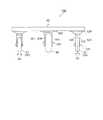
FIG. 1 is a bottom view (bottom view) of a cart according to the first embodiment of the present invention, FIG. 2 is a side view of the cart according to the present embodiment, and FIG. 3 is a front view of the cart according to the present embodiment. FIG. In the following, the traveling direction of the carriage is the front, the direction opposite to the traveling direction is the rear, the left hand direction when viewed from above facing the traveling direction is the left side, and the right hand direction is the right side (in other embodiments) The same).
本実施形態に係る台車100は、鋼鉄等の剛性材料で矩形の枠状に形成されて荷台を構成するフレーム10と、荷台の前部を支持する右前輪21および左前輪22と、荷台の後部を支持する右後輪23および左後輪24と、荷台を中央で支持する中央車輪80と、フレーム10の先端部中央に取り付けられた牽引部材としての前方連結部材41と、フレーム10の後端部中央に取り付けられた後方連結部材42とを備えている。右前輪21、左前輪22、右後輪23および左後輪24は、いずれも、鉛直軸まわりの回転を可能とされた転向車輪であるが、中央車輪80は、鉛直軸まわりの回転を不能とされた固定車輪である。これらの車輪の詳細構成については後述する。 The
フレーム10は、荷台の外枠を形成する枠状部材11と、枠状部材11の前部に取り付けられ左右方向に延びる第1および第2長尺状部材12,13と、枠状部材11の後部に取り付けられ左右方向に延びる第3および第4長尺状部材14,15と、枠状部材11の中央部に取り付けられ前後方向に延びる第5および第6長尺状部材16,17とから構成され、その上に必要に応じて剛性の板状部材(図示せず)が載置または取り付けられる。なお、フレーム10を構成する各部材11〜17は、例えばL形鋼を用いて形成される。 The
右前輪21と左前輪22は、後述の部材120,121を介して第1および第2長尺状部材12,13の右端部と左端部にそれぞれ取り付けられており、右後輪23と左後輪24は、後述の部材120,121を介して第3および第4長尺状部材14,15の右端部と左端部にそれぞれ取り付けられている。また、中央車輪80は、後述の部材220,221を介して、第5および第6長尺状部材16,17の中央部に取り付けられている。 The
本実施形態では、台車底面を構成する荷台の4隅近傍を支持する各車輪21〜24の構造およびそれをフレーム10に取り付けるための構造は同一であるが、中央車輪80の構造およびそれをフレーム10に取り付けるための構造はそれら4個の車輪21〜24とは相違する。以下では、これらの構造につき図1〜図3を参照して説明する(主として図3参照)。 In the present embodiment, the structures of the
台車底面(荷台)の4隅近傍を支持する各車輪、すなわち右前輪21、左前輪22、右後輪23および左後輪24(以下、これらの4個の車輪を総称して「4隅支持車輪」という)は、いずれも、中空構造を有さないゴム等の材料からなるソリッドタイヤを用いて構成されている。このような4隅支持車輪21〜24のそれぞれは次のようにしてフレーム10に取り付けられている。すなわち、車輪取付ベース120がフレーム10の4隅近傍の所定位置にねじ等で固定されており、この車輪取付ベース120には、鉛直方向に延びる回転軸Asを中心に回転できるように車輪支持部材121が軸支されている。車輪支持部材121は、その左右両側において所定間隔で下方に延びる2枚の板状部材123,124と、これらの板状部材123,124を垂直に貫通する車輪軸125とを備えており、車輪20(各車輪21〜24を代表させて符号“20”で示すものとする)は車輪軸125によって回転自在に軸支されている。このような構成により4隅支持車輪21〜24は、鉛直軸まわりに回転可能な転向車輪として機能する。なお、走行のための車輪軸125の位置は、図2に示すように車輪20(21〜24)の転向のための回転軸Asの位置よりも若干(所定間隔だけ)後方にずれている。 Wheels that support the vicinity of the four corners of the bottom surface (loading platform) of the carriage, that is, the
中央車輪80は、中空構造を有するゴム等の材料からなる空気入りタイヤを用いて構成されている。この中央車輪80についても、車輪取付ベース220がフレーム10の所定位置(中央部)にねじ等で固定されている。上記の4隅支持車輪21〜24の取り付けとは異なり、この車輪取付ベース220には車輪支持部材221がねじ又は溶接等によって固定されている。これにより中央車輪80は、鉛直軸まわりに回転不能(転向不能)の固定車輪となっている。この車輪支持部材221は、その左右両側において所定間隔で下方に延びる2枚の板状部材223,224と、これらの板状部材223,224を垂直に貫通する車輪軸225とを備えており、中央車輪80は車輪軸225によって回転自在に軸支されている。ここで、車輪軸225に垂直な面は台車100の前後方向に平行となっている。これにより、台車100が前後方向に進行するときに中央車輪80は滑らかに回転するが、前後方向以外の方向に進行するときには当該中央車輪80と路面との接触によって当該進行を妨げる方向に摩擦力が生じる。すなわち中央車輪80は、走行方向が台車の前後方向(直進方向)に固定された固定車輪としてフレーム10に取り付けられている。なお、図1〜図3に示すように、中央車輪80の直径は、4隅支持車輪21〜24の直径よりも若干大きくなっており、また、中央車輪80(のタイヤ)の幅も4隅支持車輪21〜24(のタイヤ)の幅よりも若干広くなっている The
牽引部材としての前方連結部材41の先端部には連結穴41hが設けられており、後方連結部材42は、上方に延びる連結ピン42pを備えている。この連結ピン42pを同構造の他の台車の前方連結部材41の連結穴41hに挿入することにより、当該台車100の後方に他の台車を連結することができる。また、同構造の他の台車の連結ピン42pを当該台車100の前方連結部材41における連結穴41hに挿入することにより、他の台車の後方に当該台車100を連結することができる。 A front end of the front connecting
<1.2 動作>
次に、本実施形態に係る台車100の動作について説明する。この台車100では、その直進方向に走行方向が固定された固定車輪としての中央車輪80がフレーム10の中央部に取り付けられており、転向車輪としての4隅支持車輪21〜24の車輪軸125の位置は、車輪20(21〜24)の転向の回転軸Asよりも若干後方にずれている(図2参照)。したがって、フレーム10に固定された前方連結部材41が台車100の前後方向(直進方向)以外の方向に牽引されると、当該台車100は中央車輪80を中心に牽引方向に応じて旋回するように振る舞い、それによって、4隅支持車輪21〜24のうち左右前輪21,22と左右後輪23,24とは逆方向に転向する。例えば、図1に示すように前方連結部材41が牽引されると、4隅支持車輪21〜24は点線で示すように転向する。したがって、台車100を右または左旋回させる場合(右または左方向に牽引される場合)において内輪差の発生を抑制することができる。<1.2 Operation>
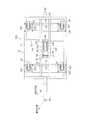
Next, operation | movement of the trolley |
図4は、本実施形態に係る台車100を複数台連結して原動機付きの牽引車500で牽引した場合の、各台車100a〜100dの走行状態を模式的に示す平面図である。この図に示すように台車100bが左方向に旋回すると、後続の台車100cにおける右前輪21および左前輪22が、その左旋回に対応する牽引方向に応じて転向する。このとき、その台車100cが固定車輪である中央車輪80を中心に左旋回するように振る舞うので、右後輪23は右前輪21の転向方向とは逆の方向に転向し、左後輪24は左前輪22の転向方向とは逆の方向に転向する。その結果、内輪差の発生が抑制され、この台車100cは、先行する台車100bの走行経路をほぼ忠実に辿ることになる。このような原理により、連結された複数台の台車100a〜100dは、すべて、先頭車両である牽引車500の走行経路をほぼ忠実に辿ることになる。 FIG. 4 is a plan view schematically showing a traveling state of each of the
<1.3 効果>
上記のように本実施形態によれば、固定車輪として台車底面(荷台)の中央部を支持する中央車輪80が設けられていることにより、図1に示すように、牽引方向に応じて右前輪21と右後輪23とが互いに逆方向に転向すると共に、左前輪22と左後輪24とが互いに逆方向に転向するので、台車100の旋回における内輪差の発生が抑制される。これにより、このような台車を複数台連結して牽引する場合には、図4に示すように、後続の台車は先行する台車の走行経路をほぼ忠実に辿ることになるので、コーナ部を有する狭い通路において、連結した複数台の台車を円滑に走行させることができる。<1.3 Effect>
As described above, according to the present embodiment, since the
また、本実施形態では、固定車輪として設けられている中央車輪80は、空気入りタイヤを用いた構成となっているので、台車100を走行させる路面(工場内の通路等)が凹凸を有していたり軟弱であったりして路面条件が良くない場合であっても、その空気入りタイヤで衝撃や振動などを吸収して路面からの影響を緩和し、直進走行および旋回走行を適切に行うことが可能となる。特に旋回走行において、空気入りタイヤを使用した中央車輪80は路面条件が良くない場合であっても路面に接した状態となるので、台車の内輪差を抑制する機能を路面条件に拘わらず保持することができる。なお、このように中央車輪80に空気入りタイヤを使用すれば、ソリッドタイヤを使用する場合に比べて、台車100が直進方向以外の方向に牽引される場合に路面との間に生じる摩擦力が大きくなる。したがって、路面条件が良好な場合であっても、中央車輪80での空気入りタイヤの使用は、上記の内輪差の抑制機能の発揮において有効である。 In the present embodiment, since the
以上のように本実施形態によれば、空気入りタイヤを使用した固定車輪としての中央車輪80を追加するという簡単な構成でコスト増を抑えつつ、旋回時の内輪差が抑制された台車を路面条件の良くない場所でも使用可能とすることができる。 As described above, according to the present embodiment, it is possible to reduce the cost with a simple configuration in which the
なお、上記実施形態では、空気入りタイヤを使用した中央車輪80の直径は、4隅支持車輪21〜24の直径よりも若干大きくなっており、また、中央車輪80の幅も4隅支持車輪の幅よりも若干広くなっている。これらは、上記のようにして旋回時の内輪差を抑制し路面からの影響を緩和する上で有効に働く。 In the above embodiment, the diameter of the
また、上記実施形態では、空気入りタイヤが使用されているのは中央車輪80だけであり、4隅支持車輪21〜24ではソリッドタイヤが使用されている。したがって、中央車輪80以外の車輪でパンクが生じることはなく、中央車輪80でパンクが生じても台車100の使用をそのまま継続することができる。 Moreover, in the said embodiment, it is only the
<1.4 変形例>
上記第1の実施形態では、空気入りタイヤが使用されるのは中央車輪80のみであるが、4隅支持車輪21〜24においてもソリッドタイヤに代えて空気入りタイヤを使用してもよい。このようにすれば、条件の悪い路面からの影響を一層緩和することができる。しかし、コストや保守性(パンク時の対応等)を考慮すれば、中央車輪80のみに空気入りタイヤを使用するのが好ましい。<1.4 Modification>
In the first embodiment, the pneumatic tire is used only for the
また、本発明に係る台車のフレームの構成は、図1に示す構成に限定されず、台車底面の4隅を支持する転向車輪が取り付けられ、台車底面(荷台)の中央部に固定車輪が取り付けられるような構成であれば、他の構成であってもよい。なお、上記第1の実施形態では、台車底面の中央部に空気入りタイヤを使用した固定車輪として1個の中央車輪80のみが取り付けられているが、このような固定車輪を台車底面の中央部に複数個(例えば台車底面中央部の前後方向に2個)取り付けるようにしてもよい。 Moreover, the structure of the frame of the trolley | bogie which concerns on this invention is not limited to the structure shown in FIG. 1, The turning wheel which supports four corners of a trolley bottom is attached, and a fixed wheel is attached to the center part of a trolley bottom (loading platform). Other configurations may be used as long as they are configured. In the first embodiment, only one
また、上記第1の実施形態では、転向車輪としての4隅支持車輪21〜24の車輪軸125の位置は、これらの車輪21〜24の転向の回転軸Asよりも若干後方にずれていて(図2参照)、これにより台車100の牽引方向に応じて4隅支持車輪21〜24が容易に転向するようになっているが、4隅支持車輪21〜24の車輪軸125の前後方向の位置(平面図上の位置)と4隅支持車輪21〜24の転向の回転軸Asの前後方向の位置(平面図上の位置)とが一致するような構成であってもよい。 Moreover, in the said 1st Embodiment, the position of the
<2.第2の実施形態>
<2.1 構成>
次に、本発明の第2の実施形態に係る台車について説明する。図5は本実施形態に係る台車の下面図(底面図)であり、図6は本実施形態に係る台車の側面図であり、図7は本実施形態に係る台車の背面図であり、図8は本実施形態における中央車輪およびその取り付け部分を示す斜視図である。なお、図7に示す背面図では、中央車輪90の取り付け部の構成をわかりやすくするために後方連結部材42を点線で示している(後述の図9においても同様)。また、図6(a)および図7(a)は、路面に置かれて中央車輪90が路面から抗力Fを受けている状態の台車102を示しており、図6(b)および図7(b)は、中央車輪90が路面から離間している状態の台車102を示している。<2. Second Embodiment>
<2.1 Configuration>
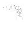
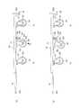
Next, a cart according to the second embodiment of the present invention will be described. 5 is a bottom view (bottom view) of the cart according to the present embodiment, FIG. 6 is a side view of the cart according to the present embodiment, and FIG. 7 is a rear view of the cart according to the present embodiment. FIG. 8 is a perspective view showing the central wheel and its mounting portion in the present embodiment. In the rear view shown in FIG. 7, the
本実施形態に係る台車102は、中央車輪90およびその取り付け部分の構成が上記第1の実施形態と相違するが、他の部分は上記第1の実施形態と同様であるので、同一部分には同一の参照符号を付して説明を省略する。 The
本実施形態では、中央車輪90は、4隅支持車輪21〜24と同様、中空構造を有さないゴム等の材料からなるソリッドタイヤを用いて構成されており、この点で、中央輪80に空気タイヤを用いた第1の実施形態と異なる。この中央車輪90を荷台の下面側に取り付けるための取り付け部は、図7および図8に示すように、蝶番243と、鋼鉄製の第1および第2の板部材241,242と、コイル状のバネ部材245と、案内棒としての第1および第2ボルト247,248とから構成されている。蝶番243は、第1の鋼鉄片243aと、第2の鋼鉄片243bと、これらの鋼鉄片243a,243bを回動自在にそれらの端部で連結する連結部243cとからなる。第1および第2の板部材241,242の一方の端部は、蝶番243の第1および第2の鋼鉄片243a,243bにそれぞれ溶接等で固定されており、これにより、第1の板部材241と第2の板部材242とは回動自在に結合されている。 In the present embodiment, the
図5に示すように、本実施形態におけるフレーム10は、枠状部材11にその中央位置よりも若干後方に取り付けられ左右方向に延びる第7長尺状部材18と、前後方向に延びる第5長尺状部材16と第6長尺状部材17との間に橋架されるように取り付けられた第8長尺部材19とを備えている。中央車輪90の取り付け部を構成する第1の板部材241は、荷台の下面側(底面)の中央部に取り付けられている。具体的には、第1の板部材241は、その両端部が溶接またはネジ等により第7長尺部材18および第8長尺部材19にそれぞれ固定されている。その第1の板部材241に対して蝶番243により回動自在に結合された第2の板部材242は、その蝶番243と結合している端部と反対側の端部に2つの貫通孔を有し、図8に示すように、案内棒としての第1および第2ボルト247,248が摺動自在にそれらの貫通孔をそれぞれ貫通している。これら第1および第2ボルト247,248の(ボルト頭と反対の)端部は、それらに螺合するナットによって第1の板部材241に固定されており、これらのボルト247,248のボルト頭によって第2の板部材242の回動角度が制限される。また、第2の板部材242は、下方に突出する円筒部246を有し、その円筒部246内にコイル状のバネ部材245の一端側が挿入され、当該バネ部材245の他端(上端)は第1の板部材241に当接または固定されている。第2の板部材242は、このバネ部材245によって下方に付勢され、中央車輪90が路面から離れた状態では、第1および第2ボルト247,248の頭で制限される位置に留まっている。 As shown in FIG. 5, the
上記第2の板部材242の下面には、中央車輪90の車輪支持部材231がねじ又は溶接等によって固定されている(図8)。これにより中央車輪90は、鉛直軸まわりに回転不能(転向不能)の固定車輪となっている。この車輪支持部材231は、その左右両側において所定間隔で下方に延びる2枚の板状部材233,234と、これらの板状部材233,234を垂直に貫通する車輪軸235とを備えており、中央車輪90は車輪軸235によって回転自在に軸支されている(図7、図8)。ここで、車輪軸235に垂直な面は台車102の前後方向に平行となっている。これにより、台車102が前後方向に進行するときに中央車輪90は滑らかに回転するが、前後方向以外の方向に進行するときには当該中央車輪90と路面との接触によって当該進行を妨げる方向に摩擦力が生じる。すなわち中央車輪90は、走行方向が台車の前後方向(直進方向)に固定された固定車輪として、上記取り付け部材を介してフレーム10に取り付けられている。 A
<2.2 効果>
上記のような本実施形態では、台車底面(荷台)の中央部を支持する中央車輪90が、走行方向を直進方向に固定された固定車輪として設けられている。これにより、図5に示すように、牽引方向に応じて右前輪21と右後輪23とが互いに逆方向に転向すると共に、左前輪22と左後輪24とが互いに逆方向に転向するので、台車102の旋回における内輪差の発生が抑制される。したがって、このような台車を複数台連結して牽引する場合には、図4に示すように、後続の台車は先行する台車の走行経路をほぼ忠実に辿ることになるので、コーナ部を有する狭い通路において、連結した複数台の台車を円滑に走行させることができる。<2.2 Effect>
In the present embodiment as described above, the
また、本実施形態では、固定車輪として設けられた中央車輪90の車輪支持部材231は第2の板部材242に固定されており、この第2の板部材242は蝶番243によって回動自在でバネ部材245によって下方向に付勢されている(図8)。このようにして中央車輪90は、蝶番243と第1および第2の板部材241,242とバネ部材245等からなる取り付け部としてのバネ機構(より一般的には弾性機構)により、上下方向(略鉛直方向)に変位可能であって走行時には下方に付勢されて路面に押圧される。したがって本実施形態によれば、台車102を走行させる路面(工場内の通路等)が凹凸を有していたり軟弱であったりして路面条件が良くない場合であっても、上記バネ機構によって衝撃や振動などを吸収して路面からの影響を緩和し、直進走行および旋回走行を適切に行うことが可能となる。特に、上記バネ機構は走行状態において中央車輪90を下方(路面方向)に押圧するので、中央車輪90は常に路面に接した状態となる。これにより、路面状況が良くない場合であっても、既述のような4隅支持車輪21〜24の転向により(図5)、台車102の旋回時における内輪差を抑制することができる。 In the present embodiment, the
さらに、本実施形態によれば、中央車輪90につき第1の実施形態における空気入りタイヤではなく、ソリッドタイヤを使用していても、第1の実施形態と同様の効果を奏することができ、しかも、路面状況に拘わらず常に中央車輪90を路面に接した状態とするという点では第1の実施形態よりも優れた効果を奏する。上記第1の実施形態では中央車輪80に空気入りタイヤを使用することで当該中央車輪80が路面から離間しないようにしているのに対し、本実施形態ではコイル形状のバネ部材245等を用いた取り付け部としてのバネ機構により中央車輪90が路面に押圧されるからである。このように本実施形態では、空気入りタイヤを使用する必要がないので、パンクが生じることがなく、台車としての耐久性が向上する。一方、上記のようなバネ機構(図8)は、全ての車輪に設ける必要なく、中央車輪90にのみ設ければよい。しかも、このバネ機構は、上記のように蝶番243と第1および第2の板部材241,242とバネ部材245等を用いた簡易な構成となっている。したがって、大きなコスト増を招くことなく、旋回時の内輪差が抑制される台車を路面条件の良くない場所でも良好に使用することが可能となる。 Furthermore, according to the present embodiment, even if a solid tire is used for the
<2.3 変形例>
上記第2の実施形態における中央車輪90の取り付け部は、図8に示した構成に限定されるものではなく、中央車輪90をバネ等(より一般的には弾性体)の弾性力によって走行時に下方に付勢して路面に押圧しつつ路面状況(路面の凹凸等)に応じて上下方向に変位可能とするような弾性機構として構成されていればよい。例えば、中央車輪90の車輪支持部材231が固定された第2の板部材242を上記第2の実施形態のように蝶番243を利用して回動可能とする構成に代えて、当該第2の板部材242を第1の板部材241(または荷台)に対し平行に上下変位可能とする構成にしてもよい。また、図8に示した取り付け部はコイル状のバネ部材245を使用した構成となっているが、これに代えて板バネを使用した構成としてもよい。また、当該取り付け部としてのバネ機構をガススプリングを使用した構成としてもよい。<2.3 Modification>
The attachment portion of the
上記第2の実施形態では、中央車輪90は1個だけ設けられているが、中央車輪をその取り付け部としてのバネ機構と共に台車の中央部において左右方向または前後方向に複数個設けてもよい。例えば図9に示すように、台車の中央部において左右方向に隣接して2個の中央車輪91,92とそれらの取り付け部を設ける構成としてもよい。このように中央車輪を複数個設ければ、荷重を分散させてタイヤの摩耗等を抑制することができる。また、路面の凹凸等の路面状況への対応性をより向上させるために中央車輪に空気入りタイヤを使用してもよく、その場合に中央車輪を複数個設ければ、1つ中央車輪でパンクが生じても台車の使用を継続することができる。なお、中央車輪を2個設ける場合、それらを左右方向に離して配置してもよいが、荷台を支持する車輪のうち同時には路面に接しない車輪の個数ができるだけ少なくなるように、図9に示す如く中央車輪を隣接して配置するのが好ましい。路面に接しない車輪(浮いた車輪)の個数が増えると、走行の安定性が低下するだけでなく、路面から浮いた車輪の空回りによって騒音が発生する等の不具合が生じるからである。 In the second embodiment, only one
10 …フレーム
21 …右前輪
22 …左前輪
23 …右後輪
24 …左後輪
41 …前方連結部材(牽引部材)
42 …後方連結部材
80 …中央車輪
90 …中央車輪
100 …台車(第1の実施形態)
102 …台車(第2の実施形態)
120,220 …車輪取付ベース
121,221 …車輪支持部材
125,225 …車輪軸
231 …車輪支持部材
235 …車輪軸
241 …第1の板部材
242 …第2の板部材
243 …蝶番
245 …バネ部材(コイルバネ)
247,248 …ボルト(案内棒)
As …車輪支持部材の回転軸(転向のための回転軸)DESCRIPTION OF
42 ... Back connecting
102. Bogie (second embodiment)
120, 220 ... wheel mounting
247, 248 ... Bolt (guide rod)
As: Rotating shaft of wheel support member (rotating shaft for turning)
Claims (11)
Translated fromJapanese前記荷台の4隅近傍をそれぞれ支持する転向可能な第1から第4の車輪と、
前記荷台の中央部を支持する転向不能な第5の車輪とを備え、
前記第5の車輪は、空気入りタイヤからなり、走行方向を直進方向に固定されていることを特徴とする、台車。Loading platform,
First to fourth convertible wheels for supporting the vicinity of the four corners of the loading platform,
A non-turnable fifth wheel that supports the center of the cargo bed,
The fifth wheel comprises a pneumatic tire, and the traveling direction is fixed in a straight traveling direction.
前記荷台の4隅近傍をそれぞれ支持する転向可能な第1から第4の車輪と、
前記荷台の中央部を支持し、走向方向を直進方向に固定された転向不能な第5の車輪と、
前記荷台と前記第5の車輪との間に介設され、前記第5の車輪を下方に付勢しつつ上下方向に変位可能とする弾性機構と
を備えることを特徴とする、台車。Loading platform,
First to fourth convertible wheels for supporting the vicinity of the four corners of the loading platform,
A fifth wheel that supports the central part of the cargo bed and is non-turnable, the running direction being fixed in the straight direction;
A cart comprising an elastic mechanism interposed between the cargo bed and the fifth wheel and capable of being displaced in the vertical direction while urging the fifth wheel downward.
前記荷台の下面側に固定された第1の板部材と、
前記第1の板部材と一端で回動自在に連結され、前記第5の車輪が回転自在に結合した第2の板部材と、
前記第1の板部材と前記第2の板部材との間に介装され、前記第2の板部材を下方に付勢するバネ部材と
を含むことを特徴とする、請求項7に記載の台車。The elastic mechanism is
A first plate member fixed to the lower surface side of the cargo bed;
A second plate member connected to the first plate member so as to be rotatable at one end, and the fifth wheel being rotatably coupled;
8. The spring according to claim 7, further comprising a spring member interposed between the first plate member and the second plate member and biasing the second plate member downward. 9. Trolley.
前記荷台と前記第5の車輪以外に少なくとも1つ備えられる転向不能な車輪との間に介設され、当該転向不能な車輪を下方に付勢しつつ上下方向に変位可能とする弾性機構を更に備えることを特徴とする、請求項7に記載の台車。At least one non-turnable wheel that supports the center of the cargo bed and that is fixed in the straight direction in the direction of travel is provided in addition to the fifth wheel,
An elastic mechanism that is interposed between the cargo bed and at least one non-turnable wheel provided other than the fifth wheel and that allows the non-turnable wheel to be displaced in the vertical direction while urging the non-turnable wheel downward. The trolley according to claim 7, comprising the trolley.
Priority Applications (3)
| Application Number | Priority Date | Filing Date | Title |
|---|---|---|---|
| JP2006307660AJP2007030882A (en) | 2006-08-24 | 2006-11-14 | Truck |
| JP2008530910AJP4339394B2 (en) | 2006-08-24 | 2007-08-21 | Trolley |
| PCT/JP2007/066160WO2008023685A1 (en) | 2006-08-24 | 2007-08-21 | Carriage |
Applications Claiming Priority (2)
| Application Number | Priority Date | Filing Date | Title |
|---|---|---|---|
| JP2006227423 | 2006-08-24 | ||
| JP2006307660AJP2007030882A (en) | 2006-08-24 | 2006-11-14 | Truck |
Publications (1)
| Publication Number | Publication Date |
|---|---|
| JP2007030882Atrue JP2007030882A (en) | 2007-02-08 |
Family
ID=37790612
Family Applications (2)
| Application Number | Title | Priority Date | Filing Date |
|---|---|---|---|
| JP2006307660APendingJP2007030882A (en) | 2006-08-24 | 2006-11-14 | Truck |
| JP2008530910AExpired - Fee RelatedJP4339394B2 (en) | 2006-08-24 | 2007-08-21 | Trolley |
Family Applications After (1)
| Application Number | Title | Priority Date | Filing Date |
|---|---|---|---|
| JP2008530910AExpired - Fee RelatedJP4339394B2 (en) | 2006-08-24 | 2007-08-21 | Trolley |
Country Status (2)
| Country | Link |
|---|---|
| JP (2) | JP2007030882A (en) |
| WO (1) | WO2008023685A1 (en) |
Cited By (5)
| Publication number | Priority date | Publication date | Assignee | Title |
|---|---|---|---|---|
| JP2008296609A (en)* | 2007-05-29 | 2008-12-11 | Tomakku:Kk | Traction truck |
| JP2012001040A (en)* | 2010-06-15 | 2012-01-05 | Tomakku Kk | Towing truck |
| KR101119510B1 (en) | 2011-10-21 | 2012-02-28 | 주식회사 맥스디앤티 | Carrier for Display Panel Aging |
| US20160347363A1 (en)* | 2014-01-28 | 2016-12-01 | Noblelift Equipment Joint Stock Co., Ltd. | Industrial vehicle capable of driving in four directions and traveling mechanism for such industrial vehicle |
| US11338834B2 (en)* | 2018-07-23 | 2022-05-24 | Pietro Laudani | Lowered bidirectional trolley |
Families Citing this family (7)
| Publication number | Priority date | Publication date | Assignee | Title |
|---|---|---|---|---|
| JP5208667B2 (en)* | 2008-10-16 | 2013-06-12 | トマック株式会社 | Trolley |
| JP2012051399A (en)* | 2010-08-31 | 2012-03-15 | Yazaki Corp | Working truck |
| JP5799157B2 (en)* | 2014-12-11 | 2015-10-21 | 矢崎総業株式会社 | Work cart |
| JP6354573B2 (en)* | 2014-12-24 | 2018-07-11 | トヨタ車体株式会社 | Transport cart |
| JP6581935B2 (en)* | 2016-03-28 | 2019-09-25 | 株式会社ピカコーポレイション | Transport cart |
| JP6839027B2 (en)* | 2017-04-24 | 2021-03-03 | 清水建設株式会社 | Transport trolley |
| USD1007091S1 (en)* | 2021-02-10 | 2023-12-05 | Intermetro Industries Corporation | Closed case cart |
Family Cites Families (9)
| Publication number | Priority date | Publication date | Assignee | Title |
|---|---|---|---|---|
| JPH0331660Y2 (en)* | 1985-06-07 | 1991-07-04 | ||
| JP3499261B2 (en)* | 1993-09-01 | 2004-02-23 | 株式会社ブリヂストン | Molding method of cable bead cord |
| JPH07101366A (en)* | 1993-10-01 | 1995-04-18 | Hisatoho Oogawara | Vehicles that can be stepped and adapters for stepping the vehicle |
| JP4019183B2 (en)* | 1997-05-07 | 2007-12-12 | ヤマト・インダストリー株式会社 | Carriage for transport and lifting caster |
| JP4336782B2 (en)* | 1999-06-30 | 2009-09-30 | ヤマト・インダストリー株式会社 | Carriage for transportation |
| JP3807260B2 (en)* | 2001-07-12 | 2006-08-09 | 株式会社ダイフク | Carriage for transportation |
| JP3807284B2 (en)* | 2001-10-25 | 2006-08-09 | 株式会社ダイフク | Carriage for transportation |
| JP2005231553A (en)* | 2004-02-20 | 2005-09-02 | Takahashi Tomoyasu | Carrying vehicle |
| JP2005349906A (en)* | 2004-06-09 | 2005-12-22 | Honko Mfg Co Ltd | Transport cart |
- 2006
- 2006-11-14JPJP2006307660Apatent/JP2007030882A/enactivePending
- 2007
- 2007-08-21JPJP2008530910Apatent/JP4339394B2/ennot_activeExpired - Fee Related
- 2007-08-21WOPCT/JP2007/066160patent/WO2008023685A1/enactiveApplication Filing
Cited By (6)
| Publication number | Priority date | Publication date | Assignee | Title |
|---|---|---|---|---|
| JP2008296609A (en)* | 2007-05-29 | 2008-12-11 | Tomakku:Kk | Traction truck |
| JP2012001040A (en)* | 2010-06-15 | 2012-01-05 | Tomakku Kk | Towing truck |
| KR101119510B1 (en) | 2011-10-21 | 2012-02-28 | 주식회사 맥스디앤티 | Carrier for Display Panel Aging |
| US20160347363A1 (en)* | 2014-01-28 | 2016-12-01 | Noblelift Equipment Joint Stock Co., Ltd. | Industrial vehicle capable of driving in four directions and traveling mechanism for such industrial vehicle |
| US9963167B2 (en)* | 2014-01-28 | 2018-05-08 | Noblelift Intelligent Equipment Co., Ltd. | Industrial vehicle capable of driving in four directions and traveling mechanism for such industrial vehicle |
| US11338834B2 (en)* | 2018-07-23 | 2022-05-24 | Pietro Laudani | Lowered bidirectional trolley |
Also Published As
| Publication number | Publication date |
|---|---|
| WO2008023685A1 (en) | 2008-02-28 |
| JPWO2008023685A1 (en) | 2010-01-14 |
| JP4339394B2 (en) | 2009-10-07 |
Similar Documents
| Publication | Publication Date | Title |
|---|---|---|
| JP4339394B2 (en) | Trolley | |
| JP6077135B2 (en) | Traveling carriage and vehicle | |
| JP4486696B1 (en) | Guide rail type vehicle cart | |
| WO2010095290A1 (en) | Bogie for guide rail system vehicle | |
| JP6102706B2 (en) | Trolley | |
| JP6467124B2 (en) | Wheel support structure for traveling cart | |
| WO2010109691A1 (en) | Bogie for rail system vehicle | |
| JP2010195310A (en) | Truck for track-type vehicle | |
| JP2015101319A (en) | Vehicle suspension device, traveling dolly, and vehicle | |
| CN110654409B (en) | Bogie and tramcar with same | |
| JP5698437B2 (en) | Toro for transporting equipment | |
| JP2009040377A (en) | Carriage | |
| JP3188939B2 (en) | Guide track type vehicle bogie | |
| JP5692507B2 (en) | Trolley | |
| JP4779683B2 (en) | Automated guided vehicle | |
| JP5220478B2 (en) | Bicycle with posture maintenance device | |
| JP4683183B2 (en) | Crawler work vehicle | |
| JP2008296609A (en) | Traction truck | |
| JP2003191861A (en) | Carriage | |
| JP2006088891A (en) | Caster | |
| CN214648637U (en) | Chassis frame of walking parts of crawler-type load-carrying robot | |
| JP2003237571A (en) | Single-axle bogies for railway vehicles | |
| JP2013241082A (en) | Rolling stock | |
| JP2009018658A (en) | Guide apparatus of guideway bus | |
| JP2011207445A (en) | Hand cart |