JP2007026063A - Security system and monitoring method - Google Patents
Security system and monitoring methodDownload PDFInfo
- Publication number
- JP2007026063A JP2007026063AJP2005207005AJP2005207005AJP2007026063AJP 2007026063 AJP2007026063 AJP 2007026063AJP 2005207005 AJP2005207005 AJP 2005207005AJP 2005207005 AJP2005207005 AJP 2005207005AJP 2007026063 AJP2007026063 AJP 2007026063A
- Authority
- JP
- Japan
- Prior art keywords
- pressure sensor
- pressure
- power line
- data signal
- abnormality
- Prior art date
- Legal status (The legal status is an assumption and is not a legal conclusion. Google has not performed a legal analysis and makes no representation as to the accuracy of the status listed.)
- Pending
Links
- 238000000034methodMethods0.000titleclaimsabstractdescription16
- 238000012544monitoring processMethods0.000titleclaimsdescription13
- 230000005856abnormalityEffects0.000claimsabstractdescription27
- 238000001514detection methodMethods0.000claimsabstractdescription6
- 238000004891communicationMethods0.000claimsdescription35
- 238000005516engineering processMethods0.000claimsdescription10
- 238000010586diagramMethods0.000description5
- 230000006870functionEffects0.000description3
- 238000009434installationMethods0.000description3
- 230000002159abnormal effectEffects0.000description2
- 230000002265preventionEffects0.000description2
- 230000008901benefitEffects0.000description1
- 238000006243chemical reactionMethods0.000description1
- 238000010276constructionMethods0.000description1
- 239000000284extractSubstances0.000description1
- 238000012986modificationMethods0.000description1
- 230000004048modificationEffects0.000description1
- 239000013307optical fiberSubstances0.000description1
- 230000008569processEffects0.000description1
- 230000004044responseEffects0.000description1
Images
Classifications
- H—ELECTRICITY
- H04—ELECTRIC COMMUNICATION TECHNIQUE
- H04B—TRANSMISSION
- H04B3/00—Line transmission systems
- H04B3/54—Systems for transmission via power distribution lines
- G—PHYSICS
- G08—SIGNALLING
- G08B—SIGNALLING OR CALLING SYSTEMS; ORDER TELEGRAPHS; ALARM SYSTEMS
- G08B13/00—Burglar, theft or intruder alarms
- G08B13/02—Mechanical actuation
- G08B13/10—Mechanical actuation by pressure on floors, floor coverings, stair treads, counters, or tills
- G—PHYSICS
- G08—SIGNALLING
- G08B—SIGNALLING OR CALLING SYSTEMS; ORDER TELEGRAPHS; ALARM SYSTEMS
- G08B25/00—Alarm systems in which the location of the alarm condition is signalled to a central station, e.g. fire or police telegraphic systems
- G08B25/01—Alarm systems in which the location of the alarm condition is signalled to a central station, e.g. fire or police telegraphic systems characterised by the transmission medium
- G08B25/06—Alarm systems in which the location of the alarm condition is signalled to a central station, e.g. fire or police telegraphic systems characterised by the transmission medium using power transmission lines
- H—ELECTRICITY
- H04—ELECTRIC COMMUNICATION TECHNIQUE
- H04B—TRANSMISSION
- H04B2203/00—Indexing scheme relating to line transmission systems
- H04B2203/54—Aspects of powerline communications not already covered by H04B3/54 and its subgroups
- H04B2203/5404—Methods of transmitting or receiving signals via power distribution lines
- H04B2203/5416—Methods of transmitting or receiving signals via power distribution lines by adding signals to the wave form of the power source
- H—ELECTRICITY
- H04—ELECTRIC COMMUNICATION TECHNIQUE
- H04B—TRANSMISSION
- H04B2203/00—Indexing scheme relating to line transmission systems
- H04B2203/54—Aspects of powerline communications not already covered by H04B3/54 and its subgroups
- H04B2203/5404—Methods of transmitting or receiving signals via power distribution lines
- H04B2203/542—Methods of transmitting or receiving signals via power distribution lines using zero crossing information
- H—ELECTRICITY
- H04—ELECTRIC COMMUNICATION TECHNIQUE
- H04B—TRANSMISSION
- H04B2203/00—Indexing scheme relating to line transmission systems
- H04B2203/54—Aspects of powerline communications not already covered by H04B3/54 and its subgroups
- H04B2203/5429—Applications for powerline communications
- H04B2203/5458—Monitor sensor; Alarm systems
Landscapes
- Engineering & Computer Science (AREA)
- Physics & Mathematics (AREA)
- General Physics & Mathematics (AREA)
- Power Engineering (AREA)
- Computer Networks & Wireless Communication (AREA)
- Signal Processing (AREA)
- Business, Economics & Management (AREA)
- Emergency Management (AREA)
- Alarm Systems (AREA)
- Telephonic Communication Services (AREA)
- Burglar Alarm Systems (AREA)
Abstract
Description
Translated fromJapaneseこの発明は、セキュリティシステムおよび監視方法に関し、特に、電力線を利用してデータ通信を行なう電力線通信技術を用いたセキュリティシステムおよび監視方法に関する。 The present invention relates to a security system and a monitoring method, and more particularly to a security system and a monitoring method using a power line communication technique for performing data communication using a power line.
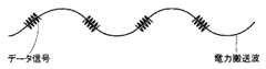
既設されている電力線を利用してデータ通信を行なうことができる電力線通信(PLC:Power Line Communication)技術は、商用電源の電力線上の電力搬送波(50〜60Hz)に高周波(たとえば、10〜450kHz)のデータ信号を重畳してデータ通信を行なうものである。データ信号に割当てられる周波数帯域が拡張されてデータ通信の高速化が進めば、インターネットに接続することも可能になる。この電力線通信技術を用いる場合、電源コンセントが設置された部屋であればどこからでもデータ通信を行なうことができ、新規配線を敷設する工事が不要で汎用性が高いというメリットがある。 A power line communication (PLC) technology capable of performing data communication using an existing power line has a high frequency (for example, 10 to 450 kHz) to a power carrier wave (50 to 60 Hz) on a power line of a commercial power source. The data signal is superimposed to perform data communication. If the frequency band allocated to the data signal is expanded to increase the speed of data communication, it is possible to connect to the Internet. When this power line communication technology is used, there is an advantage that data communication can be performed from anywhere in a room where a power outlet is installed, and construction for laying new wiring is unnecessary and the versatility is high.
近年、一般家庭においても防犯用のセキュリティシステムへの関心が高まりつつある。たとえば、下記の特許文献1には、建造物の状況を遠隔地において容易に監視することができる監視制御装置が開示されている。これによると、建造物の所定の位置に少なくとも1つ設置され、建造物内の状況を検出するセンサと、前記センサの出力信号をデジタルデータに変換するデータ変換手段と、前記デジタルデータを読取り、この読取りデータを蓄積するパソコンと、前記パソコンに蓄積されたデジタルデータをインターネットを介して送信するデータ送信手段と、前記データ送信手段によって送信されたデジタルデータを受信して、該デジタルデータをセキュリティ情報として蓄積する蓄積サーバとが設けられる。 In recent years, interest in security systems for crime prevention is also increasing in ordinary households. For example,
しかしながら、建造物内に設置されたパソコンをインターネット接続する必要があり、汎用性が低い。そこで、電力線通信技術を用いた汎用性の高いセキュリティシステムがいくつか提案されている。 However, it is necessary to connect a personal computer installed in the building to the Internet, and the versatility is low. Thus, several highly versatile security systems using power line communication technology have been proposed.
たとえば、下記の特許文献2には、不意の来訪者があった場合の無人対応を実現し、留守中における無人状態でのセキュリティを確立するセルフセキュリティシステムが開示されている。これによると、セキュリティを必要とする箇所に取付けられたセンサを介して得られる当該センサ固有のIDを、電力線ネットワークを介して受信するセキュリティ監視手段と、あらかじめ登録済みの前記センサ固有のIDと当該センサ設置箇所との対応に基づき状況の把握を行ない、当該把握された状況を携帯電話端末にメール送信するセルフセキュリティサービス提供手段とが設けられる。 For example,
また、下記の特許文献3には、異常事態が発生した時点でシステムを作動させることができ、また、専用線の設置工事が不要で設置の自由度が高いセキュリティシステムが開示されている。これによると、映像情報や音声情報などの監視情報を電力線を通信媒体として送信装置から受信装置へ配信することによって異常状態の有無を監視するセキュリティシステムにおいて、温度センサ部や音声センサ部などで構成される異常検知部によって、周囲に異常が発生しているか否かを検知する。
また、下記の特許文献4には、簡易な構成で防犯機能・証拠取得機能を備え、一般個人住宅や小規模事業所等の使用に適した高機能な防犯装置が開示されている。これによると、家庭用ビデオカメラにより撮影された不法侵入者を検知して警報装置に警報を発生させるとともに、遠隔のセンタ側端末に公衆回線を介して不法浸入を通知する。
従来より電力線通信技術を用いた汎用性の高いセキュリティシステムが提案されており、浸入者に気づかれにくく、汎用性の高い防犯用のセキュリティシステムの実現が求められている。 Conventionally, a highly versatile security system using power line communication technology has been proposed, and it is required to realize a security system for crime prevention that is not easily noticed by an intruder and has high versatility.
それゆえに、この発明の主たる目的は、浸入者に気づかれにくく、汎用性の高いセキュリティシステムおよび監視方法を提供することである。 Therefore, a main object of the present invention is to provide a highly versatile security system and monitoring method which are not easily noticed by an intruder.
この発明に係るセキュリティシステムは、電力線を利用してデータ通信を行なう電力線通信技術を用いたセキュリティシステムであって、複数行複数列に配置される複数の圧力センサで構成され、その表面に加えられる圧力を検知する圧力センサ部と、圧力センサ部から出力される圧力値の初期値を記憶する記憶部と、記憶部に記憶された初期値と圧力センサ部から出力される圧力値とを比較して、圧力センサから出力される圧力値が初期値よりも所定のしきい値以上大きくなった場合に異常検知したことを示すデータ信号を出力する制御部と、電力線上の電力搬送波にデータ信号を重畳して、所定の相手先に異常検知したことを通知するモデム部を備えたものである。 The security system according to the present invention is a security system using a power line communication technology for performing data communication using a power line, and is configured by a plurality of pressure sensors arranged in a plurality of rows and a plurality of columns, and is added to the surface thereof. The pressure sensor unit for detecting pressure, the storage unit for storing the initial value of the pressure value output from the pressure sensor unit, and the initial value stored in the storage unit and the pressure value output from the pressure sensor unit are compared. A control unit that outputs a data signal indicating that an abnormality has been detected when the pressure value output from the pressure sensor becomes greater than a predetermined threshold value from the initial value, and a data signal to the power carrier on the power line. A modem unit that superimposes and notifies a predetermined partner that an abnormality has been detected is provided.
この発明に係る他のセキュリティシステムは、電力線を利用してデータ通信を行なう電力線通信技術を用いたセキュリティシステムであって、その表面に加えられる圧力を検知する圧力センサ部と、圧力センサ部から出力される圧力値が所定値以上大きくなった場合に異常検知したことを示すデータ信号を出力する制御部と、電力線上の電力搬送波にデータ信号を重畳して、所定の相手先に異常検知したことを通知するモデム部とを備えたものである。 Another security system according to the present invention is a security system using a power line communication technique for performing data communication using a power line, a pressure sensor unit for detecting pressure applied to the surface, and an output from the pressure sensor unit A controller that outputs a data signal indicating that an abnormality has been detected when the pressure value to be applied is greater than or equal to a predetermined value, and that a data signal is superimposed on a power carrier wave on the power line and an abnormality has been detected at a predetermined destination And a modem unit for notifying the user.
好ましくは、さらに、圧力センサ部から出力される圧力値の初期値を記憶する記憶部が設けられる。制御部は、記憶部に記憶された初期値と圧力センサ部から出力される圧力値とを比較して、圧力センサから出力される圧力値が初期値よりも所定のしきい値以上大きくなった場合に異常検知したことを示すデータ信号を出力する。 Preferably, a storage unit that stores an initial value of the pressure value output from the pressure sensor unit is further provided. The control unit compares the initial value stored in the storage unit with the pressure value output from the pressure sensor unit, and the pressure value output from the pressure sensor is greater than the initial value by a predetermined threshold or more. In this case, a data signal indicating that an abnormality has been detected is output.
また好ましくは、圧力センサ部は、複数行複数列に配置される複数の圧力センサで構成される。 Preferably, the pressure sensor unit includes a plurality of pressure sensors arranged in a plurality of rows and a plurality of columns.
この発明に係る監視方法は、電力線を利用してデータ通信を行なう電力線通信技術を用いた監視方法であって、その表面に加えられる圧力を検知する圧力センサ部から出力される圧力値の初期値を記憶するステップと、記憶された初期値と圧力センサ部から出力される圧力値とを比較して、圧力センサから出力される圧力値が初期値よりも所定のしきい値以上大きくなった場合に異常検知したことを示すデータ信号を生成するステップと、電力線上の電力搬送波にデータ信号を重畳して、所定の相手先に異常検知したことを通知するステップとを含む。 A monitoring method according to the present invention is a monitoring method using a power line communication technique for performing data communication using a power line, and is an initial value of a pressure value output from a pressure sensor unit that detects a pressure applied to the surface thereof. When the stored initial value and the pressure value output from the pressure sensor unit are compared, and the pressure value output from the pressure sensor is greater than the initial value by a predetermined threshold value or more Generating a data signal indicating that an abnormality has been detected, and superimposing the data signal on a power carrier wave on the power line to notify a predetermined partner that the abnormality has been detected.
この発明によれば、圧力センサ部から出力される圧力値が変動した場合に、所定の相手先に異常検知したことが通知される。不審人物の浸入を検知するための圧力センサ部は絨毯などの一般家電に搭載されるため、浸入者に気づかれにくい。また、電力線通信技術を用いることによって、汎用性の高いセキュリティシステムおよび監視方法が実現できる。 According to this invention, when the pressure value output from the pressure sensor unit fluctuates, the predetermined partner is notified that an abnormality has been detected. Since the pressure sensor unit for detecting the intrusion of a suspicious person is mounted on a general household appliance such as a carpet, the intruder is hardly noticed. Moreover, a highly versatile security system and monitoring method can be realized by using power line communication technology.
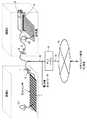
図1は、この発明の一実施の形態によるセキュリティシステムの概略構成を示すブロック図である。図1において、このセキュリティシステムは、圧力センサ付き絨毯1と、圧力センサ付き絨毯1に接続された電源プラグ2と、ベッド3と、ベッド3の下部に設置された赤外線センサ4と、赤外線センサ4に接続された電源プラグ5と、電力線ネットワークに接続された電力線6と、電力線6に接続されたコンセント7,8と、電力線6に接続されたPLCモデム9とを備える。PLCモデム9は、通信ケーブル10を介して通信網11に接続される。 FIG. 1 is a block diagram showing a schematic configuration of a security system according to an embodiment of the present invention. In FIG. 1, this security system includes a
圧力センサ付き絨毯1、電源プラグ2およびコンセント7は、部屋Aに設置される。ベッド3、赤外線センサ4、電源プラグ5およびコンセント8は、部屋Bに設置される。電力線6は、各部屋に電力供給を行なうための配電線である。電力線通信においては、電力線6が通信路として使用される。PLCモデム6は、たとえば集合住宅の電気室や屋外の電柱などに設置される。また、図示しないが、部屋の内部にPLCモデム6を設置してもよい。 The
このセキュリティシステムは、部屋Aに不審人物21が侵入した場合や、部屋Bに不審人物22が浸入した場合に、電力線6、PLCモデム9、通信ケーブル10および通信網11を介してセキュリティ会社や利用者に通知する構成になっている。 This security system is used when a
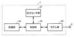
図2は、図1に示した圧力センサ付き絨毯1の内部の構成を示すブロック図である。図2において、この圧力センサ付き絨毯1は、圧力センサ部31と、記憶部32と、制御部33と、モデム部34とを含む。圧力センサ付き絨毯1は、圧力センサ部31の表面に加えられる圧力の初期値を記憶するための初期学習モードと、圧力センサ部31の表面に加えられる圧力の変動を検知するための検知動作モードとを有する。 FIG. 2 is a block diagram showing an internal configuration of the
圧力センサ部31は、圧力センサ付き絨毯1の内部に複数行複数列に配置された複数の圧力センサで構成される。この圧力センサ部31は、その表面に加えられる圧力を検知して制御部33に出力する。 The
記憶部32は、初期学習モードにおいて、圧力センサ部31から出力された圧力値を制御部33を介して受け、初期値として記憶する。これにより、圧力センサ付き絨毯1の上に置かれた家具などによる圧力値が初期値として記憶される。 The
制御部33は、検知動作モードにおいて、記憶部32に記憶された初期値を読出して圧力センサ部31から出力される圧力値と比較する。そして、圧力センサ部31から出力される圧力値が初期値よりも所定のしきい値以上大きくなった場合に、異常検知したことを示すデータ信号をモデム部34に出力する。このデータ信号は、利用者やセキュリティ会社などの通知先の情報(メールアドレスなど)、圧力センサ部31に固有のID情報などを含む。利用者やセキュリティ会社などの通知先の情報、圧力センサ部31に固有のID情報は、記憶部32に予め格納され、制御部33によって読出される。 In the detection operation mode, the
なお、異常検知したと判断するための圧力のしきい値は任意に設定することができる。これにより、たとえばしきい値よりも体重が軽い室内用ペットが部屋Aに浸入した場合は異常検知したとは判断されず、しきい値よりも体重が重い不審人物21が部屋Aに浸入した場合に異常検知したと判断されるようにすることができる。 Note that the pressure threshold value for determining that an abnormality has been detected can be arbitrarily set. Thus, for example, when a room pet whose weight is lighter than the threshold value enters the room A, it is not determined that an abnormality has been detected, and a
モデム部34は、制御部31から受けたデータ信号を電力搬送波(周波数50〜60Hz)に重畳して電源プラグ2に出力する。このモデム部34は、異常検知したことを利用者の携帯電話機やセキュリティ会社のパソコンに電子メールを送信して通知する機能を有する。ただし、通知方法は電子メールに限定されず、たとえば警報を鳴らすようにしてもよい。 The
また、利用者は携帯電話機などから圧力センサ部31を遠隔操作することができる。利用者は圧力センサ部31のオン/オフ制御を指令するデータ信号を送信する。モデム部34は、電源プラグ2を介して受けた電力搬送波からデータ信号を分離して制御部33に与える。制御部33は、モデム部34から受けたデータ信号に応答して圧力センサ31をオン/オフ制御する。 The user can remotely operate the
図3は、電力搬送波に重畳されたデータ信号を示す図である。図3に示すように、周波数50〜60Hzの電力搬送波に高周波(たとえば、10〜450kHz)のデータ信号が重畳される。 FIG. 3 is a diagram illustrating a data signal superimposed on a power carrier wave. As shown in FIG. 3, a high frequency (for example, 10 to 450 kHz) data signal is superimposed on a power carrier having a frequency of 50 to 60 Hz.
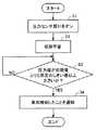
図4は、図2に示した圧力センサ付き絨毯1の動作を示すフローチャートである。図4を参照して、ステップS1において、制御部33は、利用者からの指令に応じて圧力センサ部31をオンにする。次にステップS2において、制御部33は、圧力センサ部31の表面に加えられる圧力の初期値を記憶部31に格納する初期学習動作を実行する(初期学習モード)。 FIG. 4 is a flowchart showing the operation of the
初期学習モードが終了すると検知動作モードに移行し、ステップS3において、制御部33は、記憶部32に記憶された初期値を読出して圧力センサ部31から出力される圧力値と比較する。そして、圧力センサ部31から出力される圧力値が初期値よりも所定のしきい値以上大きくなった場合は、異常検知したと判断して、ステップS4に進む。 When the initial learning mode ends, the operation mode shifts to the detection operation mode. In step S3, the
ステップS4において、制御部33は、異常検知したことを示すデータ信号をモデム部34に出力する。モデム部34は、電力線6を介してセキュリティ会社および利用者に異常検知したことを通知する。 In step S <b> 4, the
図1に戻って、PLCモデム9は、電力線6を介して受けた電力搬送波からデータ信号を抽出し、通信ケーブル(光ファイバなど)10を介して通信網11に与える。これにより、不審人物が浸入したことがセキュリティ会社のパソコンや利用者の携帯電話機に通知される。セキュリティ会社との契約時に、圧力センサ部31に固有のID情報および自宅の住所を登録しておくことによって、不審人物が浸入した際に警備員の出動を要請することができる。また、利用者の携帯電話機に通知することによって、不審人物が浸入したことを利用者が外出先で知ることができる。なお、引越しをした場合などでもセキュリティ会社に登録した住所を変更をするだけで、容易に契約変更することができる。 Returning to FIG. 1, the PLC modem 9 extracts a data signal from a power carrier wave received via the
部屋Bにおいて、赤外線センサ4はベッド3の下部など、侵入者に気づかれにくい場所に設置される。この赤外線センサ4は、たとえば電灯と一体化されたものであってもよい。赤外線センサ4は、所定の範囲に線状または面状(図では線状)の赤外線ビームを放射する。赤外線センサ4の構成は、図2に示した圧力センサ付き絨毯1の構成と同様である。赤外線ビームを浸入者が横切った場合、赤外線センサ4が不審人物の浸入を感知する。この場合も、圧力センサ付き絨毯1が異常検知した場合と同様に、不審人物が浸入したことがセキュリティ会社および利用者に通知される。 In the room B, the infrared sensor 4 is installed in a place such as the lower part of the
以上のように、この一実施の形態では、不審人物の浸入を検知するためのセンサが絨毯や電灯などの一般家電に搭載されるため、浸入者に気づかれにくい。また、電力線通信技術を用いることによって、汎用性の高いセキュリティシステムおよび監視方法が実現できる。 As described above, in this embodiment, since a sensor for detecting the intrusion of a suspicious person is mounted on a general household appliance such as a carpet or an electric light, the intruder is hardly noticed. Moreover, a highly versatile security system and monitoring method can be realized by using power line communication technology.
今回開示された実施の形態はすべての点で例示であって制限的なものではないと考えられるべきである。本発明の範囲は上記した説明ではなくて特許請求の範囲によって示され、特許請求の範囲と均等の意味および範囲内でのすべての変更が含まれることが意図される。 The embodiment disclosed this time should be considered as illustrative in all points and not restrictive. The scope of the present invention is defined by the terms of the claims, rather than the description above, and is intended to include any modifications within the scope and meaning equivalent to the terms of the claims.
1 圧力センサ付き絨毯、2 電源プラグ、3 ベッド、4 赤外線センサ、5 電源プラグ、6 電力線、7,8 コンセント、9 PLCモデム、10 通信ケーブル、11 通信網、21,22 不審人物、31 圧力センサ部、32 記憶部、33 制御部、34 モデム部。 1 carpet with pressure sensor, 2 power plug, 3 bed, 4 infrared sensor, 5 power plug, 6 power line, 7, 8 outlet, 9 PLC modem, 10 communication cable, 11 communication network, 21, 22 suspicious person, 31 pressure sensor Part, 32 storage part, 33 control part, 34 modem part.
Claims (5)
Translated fromJapanese複数行複数列に配置される複数の圧力センサで構成され、その表面に加えられる圧力を検知する圧力センサ部、
前記圧力センサ部から出力される圧力値の初期値を記憶する記憶部、
前記記憶部に記憶された前記初期値と前記圧力センサ部から出力される圧力値とを比較して、前記圧力センサから出力される圧力値が前記初期値よりも所定のしきい値以上大きくなった場合に異常検知したことを示すデータ信号を出力する制御部、および
前記電力線上の電力搬送波に前記データ信号を重畳して、所定の相手先に異常検知したことを通知するモデム部を備える、セキュリティシステム。A security system using power line communication technology for performing data communication using a power line,
A pressure sensor unit configured by a plurality of pressure sensors arranged in a plurality of rows and a plurality of columns and detecting pressure applied to the surface thereof,
A storage unit for storing an initial value of a pressure value output from the pressure sensor unit;
The initial value stored in the storage unit is compared with the pressure value output from the pressure sensor unit, and the pressure value output from the pressure sensor is greater than the initial value by a predetermined threshold value or more. A control unit that outputs a data signal indicating that an abnormality has been detected, and a modem unit that superimposes the data signal on a power carrier on the power line and notifies a predetermined partner that an abnormality has been detected, Security system.
その表面に加えられる圧力を検知する圧力センサ部、
前記圧力センサ部から出力される圧力値が所定値以上大きくなった場合に異常検知したことを示すデータ信号を出力する制御部、および
前記電力線上の電力搬送波に前記データ信号を重畳して、所定の相手先に異常検知したことを通知するモデム部を備える、セキュリティシステム。A security system using power line communication technology for performing data communication using a power line,
A pressure sensor for detecting the pressure applied to the surface,
A control unit that outputs a data signal indicating that an abnormality has been detected when the pressure value output from the pressure sensor unit is greater than or equal to a predetermined value; and the data signal is superimposed on a power carrier wave on the power line, A security system comprising a modem unit for notifying the other party that an abnormality has been detected.
前記制御部は、前記記憶部に記憶された前記初期値と前記圧力センサ部から出力される圧力値とを比較して、前記圧力センサから出力される圧力値が前記初期値よりも所定のしきい値以上大きくなった場合に異常検知したことを示すデータ信号を出力する、請求項2に記載のセキュリティシステム。Furthermore, a storage unit that stores an initial value of the pressure value output from the pressure sensor unit,
The control unit compares the initial value stored in the storage unit with the pressure value output from the pressure sensor unit, and the pressure value output from the pressure sensor is greater than the initial value. The security system according to claim 2, wherein a data signal indicating that an abnormality has been detected is output when the threshold value exceeds a threshold value.
その表面に加えられる圧力を検知する圧力センサ部から出力される圧力値の初期値を記憶するステップ、
記憶された前記初期値と前記圧力センサ部から出力される圧力値とを比較して、前記圧力センサから出力される圧力値が前記初期値よりも所定のしきい値以上大きくなった場合に異常検知したことを示すデータ信号を生成するステップ、および
前記電力線上の電力搬送波に前記データ信号を重畳して、所定の相手先に異常検知したことを通知するステップを含む、監視方法。A monitoring method using power line communication technology for performing data communication using a power line,
Storing an initial value of a pressure value output from a pressure sensor unit that detects a pressure applied to the surface;
The stored initial value is compared with the pressure value output from the pressure sensor unit, and an abnormality occurs when the pressure value output from the pressure sensor is greater than the initial value by a predetermined threshold value or more. A monitoring method, comprising: generating a data signal indicating detection; and superimposing the data signal on a power carrier wave on the power line to notify a predetermined counterpart that an abnormality has been detected.
Priority Applications (4)
| Application Number | Priority Date | Filing Date | Title |
|---|---|---|---|
| JP2005207005AJP2007026063A (en) | 2005-07-15 | 2005-07-15 | Security system and monitoring method |
| US11/486,677US7504938B2 (en) | 2005-07-15 | 2006-07-14 | Security system and monitoring method using power line communication technology |
| CNA2006101056813ACN1897476A (en) | 2005-07-15 | 2006-07-17 | Security system and monitoring method using power line communication technology |
| EP06014866AEP1744289B1 (en) | 2005-07-15 | 2006-07-17 | Security system and monitoring method using power line communication technology |
Applications Claiming Priority (1)
| Application Number | Priority Date | Filing Date | Title |
|---|---|---|---|
| JP2005207005AJP2007026063A (en) | 2005-07-15 | 2005-07-15 | Security system and monitoring method |
Publications (1)
| Publication Number | Publication Date |
|---|---|
| JP2007026063Atrue JP2007026063A (en) | 2007-02-01 |
Family
ID=37401531
Family Applications (1)
| Application Number | Title | Priority Date | Filing Date |
|---|---|---|---|
| JP2005207005APendingJP2007026063A (en) | 2005-07-15 | 2005-07-15 | Security system and monitoring method |
Country Status (4)
| Country | Link |
|---|---|
| US (1) | US7504938B2 (en) |
| EP (1) | EP1744289B1 (en) |
| JP (1) | JP2007026063A (en) |
| CN (1) | CN1897476A (en) |
Cited By (3)
| Publication number | Priority date | Publication date | Assignee | Title |
|---|---|---|---|---|
| JP2009032020A (en)* | 2007-07-26 | 2009-02-12 | Panasonic Electric Works Co Ltd | Crime prevention lighting system |
| JP2013186716A (en)* | 2012-03-08 | 2013-09-19 | Sony Corp | Discriminating apparatus, discriminating method and discriminating system |
| JP2016039450A (en)* | 2014-08-06 | 2016-03-22 | 三井不動産株式会社 | Monitoring system and monitoring method |
Families Citing this family (127)
| Publication number | Priority date | Publication date | Assignee | Title |
|---|---|---|---|---|
| CN102064883B (en)* | 2010-08-27 | 2013-03-27 | 天津大学 | Operational decision making system of lumped control multi-type heterogeneous electricity communication network |
| CN102403785B (en)* | 2010-09-07 | 2014-07-16 | 鸿富锦精密工业(深圳)有限公司 | Power supply management device and power supply management method |
| CN101984471A (en)* | 2010-11-22 | 2011-03-09 | 武汉理工大学 | Intelligent anti-theft ground pad based on diffuse carbon fiber materials and application thereof |
| TW201437927A (en)* | 2013-03-27 | 2014-10-01 | Hon Hai Prec Ind Co Ltd | Personal position system and position method |
| US9525524B2 (en) | 2013-05-31 | 2016-12-20 | At&T Intellectual Property I, L.P. | Remote distributed antenna system |
| US9999038B2 (en) | 2013-05-31 | 2018-06-12 | At&T Intellectual Property I, L.P. | Remote distributed antenna system |
| US8897697B1 (en) | 2013-11-06 | 2014-11-25 | At&T Intellectual Property I, Lp | Millimeter-wave surface-wave communications |
| US9768833B2 (en) | 2014-09-15 | 2017-09-19 | At&T Intellectual Property I, L.P. | Method and apparatus for sensing a condition in a transmission medium of electromagnetic waves |
| US10063280B2 (en) | 2014-09-17 | 2018-08-28 | At&T Intellectual Property I, L.P. | Monitoring and mitigating conditions in a communication network |
| US9615269B2 (en) | 2014-10-02 | 2017-04-04 | At&T Intellectual Property I, L.P. | Method and apparatus that provides fault tolerance in a communication network |
| US9685992B2 (en) | 2014-10-03 | 2017-06-20 | At&T Intellectual Property I, L.P. | Circuit panel network and methods thereof |
| US9503189B2 (en) | 2014-10-10 | 2016-11-22 | At&T Intellectual Property I, L.P. | Method and apparatus for arranging communication sessions in a communication system |
| US9973299B2 (en) | 2014-10-14 | 2018-05-15 | At&T Intellectual Property I, L.P. | Method and apparatus for adjusting a mode of communication in a communication network |
| US9769020B2 (en) | 2014-10-21 | 2017-09-19 | At&T Intellectual Property I, L.P. | Method and apparatus for responding to events affecting communications in a communication network |
| US9653770B2 (en) | 2014-10-21 | 2017-05-16 | At&T Intellectual Property I, L.P. | Guided wave coupler, coupling module and methods for use therewith |
| US9627768B2 (en) | 2014-10-21 | 2017-04-18 | At&T Intellectual Property I, L.P. | Guided-wave transmission device with non-fundamental mode propagation and methods for use therewith |
| US9312919B1 (en) | 2014-10-21 | 2016-04-12 | At&T Intellectual Property I, Lp | Transmission device with impairment compensation and methods for use therewith |
| US9780834B2 (en) | 2014-10-21 | 2017-10-03 | At&T Intellectual Property I, L.P. | Method and apparatus for transmitting electromagnetic waves |
| US9577306B2 (en) | 2014-10-21 | 2017-02-21 | At&T Intellectual Property I, L.P. | Guided-wave transmission device and methods for use therewith |
| US9997819B2 (en) | 2015-06-09 | 2018-06-12 | At&T Intellectual Property I, L.P. | Transmission medium and method for facilitating propagation of electromagnetic waves via a core |
| US9461706B1 (en) | 2015-07-31 | 2016-10-04 | At&T Intellectual Property I, Lp | Method and apparatus for exchanging communication signals |
| US9954287B2 (en) | 2014-11-20 | 2018-04-24 | At&T Intellectual Property I, L.P. | Apparatus for converting wireless signals and electromagnetic waves and methods thereof |
| US10340573B2 (en) | 2016-10-26 | 2019-07-02 | At&T Intellectual Property I, L.P. | Launcher with cylindrical coupling device and methods for use therewith |
| US9742462B2 (en) | 2014-12-04 | 2017-08-22 | At&T Intellectual Property I, L.P. | Transmission medium and communication interfaces and methods for use therewith |
| US10243784B2 (en) | 2014-11-20 | 2019-03-26 | At&T Intellectual Property I, L.P. | System for generating topology information and methods thereof |
| US9544006B2 (en) | 2014-11-20 | 2017-01-10 | At&T Intellectual Property I, L.P. | Transmission device with mode division multiplexing and methods for use therewith |
| US9800327B2 (en) | 2014-11-20 | 2017-10-24 | At&T Intellectual Property I, L.P. | Apparatus for controlling operations of a communication device and methods thereof |
| US10009067B2 (en) | 2014-12-04 | 2018-06-26 | At&T Intellectual Property I, L.P. | Method and apparatus for configuring a communication interface |
| CN104390652A (en)* | 2014-12-02 | 2015-03-04 | 国网上海市电力公司 | Intelligent navigation system for addresses of substations |
| US9876570B2 (en) | 2015-02-20 | 2018-01-23 | At&T Intellectual Property I, Lp | Guided-wave transmission device with non-fundamental mode propagation and methods for use therewith |
| US9749013B2 (en) | 2015-03-17 | 2017-08-29 | At&T Intellectual Property I, L.P. | Method and apparatus for reducing attenuation of electromagnetic waves guided by a transmission medium |
| US10224981B2 (en) | 2015-04-24 | 2019-03-05 | At&T Intellectual Property I, Lp | Passive electrical coupling device and methods for use therewith |
| US9705561B2 (en) | 2015-04-24 | 2017-07-11 | At&T Intellectual Property I, L.P. | Directional coupling device and methods for use therewith |
| US9793954B2 (en) | 2015-04-28 | 2017-10-17 | At&T Intellectual Property I, L.P. | Magnetic coupling device and methods for use therewith |
| US9871282B2 (en) | 2015-05-14 | 2018-01-16 | At&T Intellectual Property I, L.P. | At least one transmission medium having a dielectric surface that is covered at least in part by a second dielectric |
| US9748626B2 (en) | 2015-05-14 | 2017-08-29 | At&T Intellectual Property I, L.P. | Plurality of cables having different cross-sectional shapes which are bundled together to form a transmission medium |
| US9490869B1 (en) | 2015-05-14 | 2016-11-08 | At&T Intellectual Property I, L.P. | Transmission medium having multiple cores and methods for use therewith |
| US10650940B2 (en) | 2015-05-15 | 2020-05-12 | At&T Intellectual Property I, L.P. | Transmission medium having a conductive material and methods for use therewith |
| US9917341B2 (en) | 2015-05-27 | 2018-03-13 | At&T Intellectual Property I, L.P. | Apparatus and method for launching electromagnetic waves and for modifying radial dimensions of the propagating electromagnetic waves |
| US9866309B2 (en) | 2015-06-03 | 2018-01-09 | At&T Intellectual Property I, Lp | Host node device and methods for use therewith |
| US9912381B2 (en) | 2015-06-03 | 2018-03-06 | At&T Intellectual Property I, Lp | Network termination and methods for use therewith |
| US10812174B2 (en) | 2015-06-03 | 2020-10-20 | At&T Intellectual Property I, L.P. | Client node device and methods for use therewith |
| US9913139B2 (en) | 2015-06-09 | 2018-03-06 | At&T Intellectual Property I, L.P. | Signal fingerprinting for authentication of communicating devices |
| US9820146B2 (en) | 2015-06-12 | 2017-11-14 | At&T Intellectual Property I, L.P. | Method and apparatus for authentication and identity management of communicating devices |
| US9865911B2 (en) | 2015-06-25 | 2018-01-09 | At&T Intellectual Property I, L.P. | Waveguide system for slot radiating first electromagnetic waves that are combined into a non-fundamental wave mode second electromagnetic wave on a transmission medium |
| US9509415B1 (en) | 2015-06-25 | 2016-11-29 | At&T Intellectual Property I, L.P. | Methods and apparatus for inducing a fundamental wave mode on a transmission medium |
| US9640850B2 (en) | 2015-06-25 | 2017-05-02 | At&T Intellectual Property I, L.P. | Methods and apparatus for inducing a non-fundamental wave mode on a transmission medium |
| US10148016B2 (en) | 2015-07-14 | 2018-12-04 | At&T Intellectual Property I, L.P. | Apparatus and methods for communicating utilizing an antenna array |
| US9853342B2 (en) | 2015-07-14 | 2017-12-26 | At&T Intellectual Property I, L.P. | Dielectric transmission medium connector and methods for use therewith |
| US9628116B2 (en) | 2015-07-14 | 2017-04-18 | At&T Intellectual Property I, L.P. | Apparatus and methods for transmitting wireless signals |
| US9847566B2 (en) | 2015-07-14 | 2017-12-19 | At&T Intellectual Property I, L.P. | Method and apparatus for adjusting a field of a signal to mitigate interference |
| US10205655B2 (en) | 2015-07-14 | 2019-02-12 | At&T Intellectual Property I, L.P. | Apparatus and methods for communicating utilizing an antenna array and multiple communication paths |
| US9882257B2 (en) | 2015-07-14 | 2018-01-30 | At&T Intellectual Property I, L.P. | Method and apparatus for launching a wave mode that mitigates interference |
| US10044409B2 (en) | 2015-07-14 | 2018-08-07 | At&T Intellectual Property I, L.P. | Transmission medium and methods for use therewith |
| US10090606B2 (en) | 2015-07-15 | 2018-10-02 | At&T Intellectual Property I, L.P. | Antenna system with dielectric array and methods for use therewith |
| US9948333B2 (en) | 2015-07-23 | 2018-04-17 | At&T Intellectual Property I, L.P. | Method and apparatus for wireless communications to mitigate interference |
| US9912027B2 (en) | 2015-07-23 | 2018-03-06 | At&T Intellectual Property I, L.P. | Method and apparatus for exchanging communication signals |
| US9871283B2 (en) | 2015-07-23 | 2018-01-16 | At&T Intellectual Property I, Lp | Transmission medium having a dielectric core comprised of plural members connected by a ball and socket configuration |
| US9749053B2 (en) | 2015-07-23 | 2017-08-29 | At&T Intellectual Property I, L.P. | Node device, repeater and methods for use therewith |
| US9967173B2 (en) | 2015-07-31 | 2018-05-08 | At&T Intellectual Property I, L.P. | Method and apparatus for authentication and identity management of communicating devices |
| US9735833B2 (en) | 2015-07-31 | 2017-08-15 | At&T Intellectual Property I, L.P. | Method and apparatus for communications management in a neighborhood network |
| US9904535B2 (en) | 2015-09-14 | 2018-02-27 | At&T Intellectual Property I, L.P. | Method and apparatus for distributing software |
| US9769128B2 (en) | 2015-09-28 | 2017-09-19 | At&T Intellectual Property I, L.P. | Method and apparatus for encryption of communications over a network |
| US9729197B2 (en) | 2015-10-01 | 2017-08-08 | At&T Intellectual Property I, L.P. | Method and apparatus for communicating network management traffic over a network |
| US9876264B2 (en) | 2015-10-02 | 2018-01-23 | At&T Intellectual Property I, Lp | Communication system, guided wave switch and methods for use therewith |
| CN105261131B (en)* | 2015-10-12 | 2018-07-31 | 小米科技有限责任公司 | A kind of method and apparatus sending alert notification messages |
| US10355367B2 (en) | 2015-10-16 | 2019-07-16 | At&T Intellectual Property I, L.P. | Antenna structure for exchanging wireless signals |
| CN106228771A (en)* | 2016-08-15 | 2016-12-14 | 周红林 | A kind of object recovering system based on intelligent carpet |
| US9860075B1 (en) | 2016-08-26 | 2018-01-02 | At&T Intellectual Property I, L.P. | Method and communication node for broadband distribution |
| US10268166B2 (en) | 2016-09-15 | 2019-04-23 | Otis Elevator Company | Intelligent surface systems for building solutions |
| US10374316B2 (en) | 2016-10-21 | 2019-08-06 | At&T Intellectual Property I, L.P. | System and dielectric antenna with non-uniform dielectric |
| US10811767B2 (en) | 2016-10-21 | 2020-10-20 | At&T Intellectual Property I, L.P. | System and dielectric antenna with convex dielectric radome |
| US10312567B2 (en) | 2016-10-26 | 2019-06-04 | At&T Intellectual Property I, L.P. | Launcher with planar strip antenna and methods for use therewith |
| US10224634B2 (en) | 2016-11-03 | 2019-03-05 | At&T Intellectual Property I, L.P. | Methods and apparatus for adjusting an operational characteristic of an antenna |
| US10498044B2 (en) | 2016-11-03 | 2019-12-03 | At&T Intellectual Property I, L.P. | Apparatus for configuring a surface of an antenna |
| US10291334B2 (en) | 2016-11-03 | 2019-05-14 | At&T Intellectual Property I, L.P. | System for detecting a fault in a communication system |
| US10225025B2 (en) | 2016-11-03 | 2019-03-05 | At&T Intellectual Property I, L.P. | Method and apparatus for detecting a fault in a communication system |
| US10090594B2 (en) | 2016-11-23 | 2018-10-02 | At&T Intellectual Property I, L.P. | Antenna system having structural configurations for assembly |
| US10178445B2 (en) | 2016-11-23 | 2019-01-08 | At&T Intellectual Property I, L.P. | Methods, devices, and systems for load balancing between a plurality of waveguides |
| US10340603B2 (en) | 2016-11-23 | 2019-07-02 | At&T Intellectual Property I, L.P. | Antenna system having shielded structural configurations for assembly |
| US10535928B2 (en) | 2016-11-23 | 2020-01-14 | At&T Intellectual Property I, L.P. | Antenna system and methods for use therewith |
| US10340601B2 (en) | 2016-11-23 | 2019-07-02 | At&T Intellectual Property I, L.P. | Multi-antenna system and methods for use therewith |
| US10361489B2 (en) | 2016-12-01 | 2019-07-23 | At&T Intellectual Property I, L.P. | Dielectric dish antenna system and methods for use therewith |
| US10305190B2 (en) | 2016-12-01 | 2019-05-28 | At&T Intellectual Property I, L.P. | Reflecting dielectric antenna system and methods for use therewith |
| US10135145B2 (en) | 2016-12-06 | 2018-11-20 | At&T Intellectual Property I, L.P. | Apparatus and methods for generating an electromagnetic wave along a transmission medium |
| US10326494B2 (en) | 2016-12-06 | 2019-06-18 | At&T Intellectual Property I, L.P. | Apparatus for measurement de-embedding and methods for use therewith |
| US10819035B2 (en) | 2016-12-06 | 2020-10-27 | At&T Intellectual Property I, L.P. | Launcher with helical antenna and methods for use therewith |
| US10637149B2 (en) | 2016-12-06 | 2020-04-28 | At&T Intellectual Property I, L.P. | Injection molded dielectric antenna and methods for use therewith |
| US10727599B2 (en) | 2016-12-06 | 2020-07-28 | At&T Intellectual Property I, L.P. | Launcher with slot antenna and methods for use therewith |
| US10755542B2 (en) | 2016-12-06 | 2020-08-25 | At&T Intellectual Property I, L.P. | Method and apparatus for surveillance via guided wave communication |
| US10439675B2 (en) | 2016-12-06 | 2019-10-08 | At&T Intellectual Property I, L.P. | Method and apparatus for repeating guided wave communication signals |
| US9927517B1 (en) | 2016-12-06 | 2018-03-27 | At&T Intellectual Property I, L.P. | Apparatus and methods for sensing rainfall |
| US10382976B2 (en) | 2016-12-06 | 2019-08-13 | At&T Intellectual Property I, L.P. | Method and apparatus for managing wireless communications based on communication paths and network device positions |
| US10020844B2 (en) | 2016-12-06 | 2018-07-10 | T&T Intellectual Property I, L.P. | Method and apparatus for broadcast communication via guided waves |
| US10694379B2 (en) | 2016-12-06 | 2020-06-23 | At&T Intellectual Property I, L.P. | Waveguide system with device-based authentication and methods for use therewith |
| US10027397B2 (en) | 2016-12-07 | 2018-07-17 | At&T Intellectual Property I, L.P. | Distributed antenna system and methods for use therewith |
| US10139820B2 (en) | 2016-12-07 | 2018-11-27 | At&T Intellectual Property I, L.P. | Method and apparatus for deploying equipment of a communication system |
| US10168695B2 (en) | 2016-12-07 | 2019-01-01 | At&T Intellectual Property I, L.P. | Method and apparatus for controlling an unmanned aircraft |
| US10359749B2 (en) | 2016-12-07 | 2019-07-23 | At&T Intellectual Property I, L.P. | Method and apparatus for utilities management via guided wave communication |
| US10243270B2 (en) | 2016-12-07 | 2019-03-26 | At&T Intellectual Property I, L.P. | Beam adaptive multi-feed dielectric antenna system and methods for use therewith |
| US9893795B1 (en) | 2016-12-07 | 2018-02-13 | At&T Intellectual Property I, Lp | Method and repeater for broadband distribution |
| US10446936B2 (en) | 2016-12-07 | 2019-10-15 | At&T Intellectual Property I, L.P. | Multi-feed dielectric antenna system and methods for use therewith |
| US10547348B2 (en) | 2016-12-07 | 2020-01-28 | At&T Intellectual Property I, L.P. | Method and apparatus for switching transmission mediums in a communication system |
| US10389029B2 (en) | 2016-12-07 | 2019-08-20 | At&T Intellectual Property I, L.P. | Multi-feed dielectric antenna system with core selection and methods for use therewith |
| US10326689B2 (en) | 2016-12-08 | 2019-06-18 | At&T Intellectual Property I, L.P. | Method and system for providing alternative communication paths |
| US10530505B2 (en) | 2016-12-08 | 2020-01-07 | At&T Intellectual Property I, L.P. | Apparatus and methods for launching electromagnetic waves along a transmission medium |
| US10601494B2 (en) | 2016-12-08 | 2020-03-24 | At&T Intellectual Property I, L.P. | Dual-band communication device and method for use therewith |
| US10069535B2 (en) | 2016-12-08 | 2018-09-04 | At&T Intellectual Property I, L.P. | Apparatus and methods for launching electromagnetic waves having a certain electric field structure |
| US10938108B2 (en) | 2016-12-08 | 2021-03-02 | At&T Intellectual Property I, L.P. | Frequency selective multi-feed dielectric antenna system and methods for use therewith |
| US10777873B2 (en) | 2016-12-08 | 2020-09-15 | At&T Intellectual Property I, L.P. | Method and apparatus for mounting network devices |
| US10411356B2 (en) | 2016-12-08 | 2019-09-10 | At&T Intellectual Property I, L.P. | Apparatus and methods for selectively targeting communication devices with an antenna array |
| US10389037B2 (en) | 2016-12-08 | 2019-08-20 | At&T Intellectual Property I, L.P. | Apparatus and methods for selecting sections of an antenna array and use therewith |
| US10916969B2 (en) | 2016-12-08 | 2021-02-09 | At&T Intellectual Property I, L.P. | Method and apparatus for providing power using an inductive coupling |
| US9911020B1 (en) | 2016-12-08 | 2018-03-06 | At&T Intellectual Property I, L.P. | Method and apparatus for tracking via a radio frequency identification device |
| US10103422B2 (en) | 2016-12-08 | 2018-10-16 | At&T Intellectual Property I, L.P. | Method and apparatus for mounting network devices |
| US9998870B1 (en) | 2016-12-08 | 2018-06-12 | At&T Intellectual Property I, L.P. | Method and apparatus for proximity sensing |
| US9838896B1 (en) | 2016-12-09 | 2017-12-05 | At&T Intellectual Property I, L.P. | Method and apparatus for assessing network coverage |
| US10264586B2 (en) | 2016-12-09 | 2019-04-16 | At&T Mobility Ii Llc | Cloud-based packet controller and methods for use therewith |
| US10340983B2 (en) | 2016-12-09 | 2019-07-02 | At&T Intellectual Property I, L.P. | Method and apparatus for surveying remote sites via guided wave communications |
| US9973940B1 (en) | 2017-02-27 | 2018-05-15 | At&T Intellectual Property I, L.P. | Apparatus and methods for dynamic impedance matching of a guided wave launcher |
| US10298293B2 (en) | 2017-03-13 | 2019-05-21 | At&T Intellectual Property I, L.P. | Apparatus of communication utilizing wireless network devices |
| US20190208018A1 (en) | 2018-01-02 | 2019-07-04 | Scanalytics, Inc. | System and method for smart building control using multidimensional presence sensor arrays |
| CN108831078A (en)* | 2018-08-31 | 2018-11-16 | 天津中德应用技术大学 | A kind of security protection system with duplicate protection measure |
| CN110838215A (en)* | 2019-12-09 | 2020-02-25 | 重庆第二师范学院 | Perimeter security intrusion monitoring optical fiber sensor for improving travel safety and monitoring method |
| CN114826328B (en)* | 2022-03-15 | 2024-03-29 | 宝信软件(武汉)有限公司 | Piping lane communication system and method based on power carrier |
| US20230346195A1 (en)* | 2022-04-28 | 2023-11-02 | Sabestian Magan | Doormat Device |
| CN114900408A (en)* | 2022-05-09 | 2022-08-12 | 北京芯联心科技发展有限公司 | ID information modulation method in-vivo and in-vitro wireless communication system |
Citations (6)
| Publication number | Priority date | Publication date | Assignee | Title |
|---|---|---|---|---|
| JPH11306447A (en)* | 1998-04-23 | 1999-11-05 | Mitsubishi Electric Corp | Intrusion monitoring device |
| JP2003044961A (en)* | 2001-08-01 | 2003-02-14 | Omron Corp | Monitor mode setting device, monitor mode setting promotion program, recording medium where the monitor mode setting promotion program is recorded, and monitor system |
| JP2003151051A (en)* | 2001-11-08 | 2003-05-23 | Yamatake Corp | Emergency call system |
| JP2003168176A (en)* | 2001-11-30 | 2003-06-13 | Matsushita Electric Works Ltd | Warning system |
| JP2004295408A (en)* | 2003-03-26 | 2004-10-21 | Matsushita Electric Works Ltd | Control and monitor integrated system for residence |
| JP2005011219A (en)* | 2003-06-20 | 2005-01-13 | Matsushita Electric Works Ltd | Emergency call system |
Family Cites Families (14)
| Publication number | Priority date | Publication date | Assignee | Title |
|---|---|---|---|---|
| US3838411A (en)* | 1973-01-02 | 1974-09-24 | Rapistan Inc | Detection system |
| US4347505A (en)* | 1979-01-29 | 1982-08-31 | Antroy Enterprises, Inc. | Device for controlling a circuit |
| EP0529926A1 (en) | 1991-08-27 | 1993-03-03 | Ian E. Kibblewhite | Remote sensor for monitoring departure from bed |
| US6111509A (en) | 1998-02-26 | 2000-08-29 | Bed-Check Corporation | Microprocessor based bed patient monitor |
| US6515586B1 (en)* | 1998-12-18 | 2003-02-04 | Intel Corporation | Tactile tracking systems and methods |
| WO2001037438A1 (en)* | 1999-11-15 | 2001-05-25 | Interlogix, Inc. | Highly reliable power line communications system |
| US6249223B1 (en)* | 2000-01-31 | 2001-06-19 | Dean Everett Christensen | Modular alarm system |
| US6998962B2 (en) | 2000-04-14 | 2006-02-14 | Current Technologies, Llc | Power line communication apparatus and method of using the same |
| JP2002183845A (en) | 2000-12-15 | 2002-06-28 | Toko Electric Corp | Security equipment |
| US20020158775A1 (en)* | 2001-04-27 | 2002-10-31 | Wallace David A. | Telemetry system and method for home-based diagnostic and monitoring devices |
| JP2002373389A (en) | 2001-06-15 | 2002-12-26 | Matsushita Electric Ind Co Ltd | Security system |
| JP2003023678A (en) | 2001-07-06 | 2003-01-24 | Nippon Telegraph & Telephone West Corp | Supervisory control system, and supervisory method |
| JP2003331371A (en) | 2002-05-15 | 2003-11-21 | Net Community Kikaku:Kk | Self-security system, security monitoring method, self- security service providing program and recording medium |
| US7129423B2 (en)* | 2003-06-04 | 2006-10-31 | Herdstar, Llc | Automatic livestock weighing system |
- 2005
- 2005-07-15JPJP2005207005Apatent/JP2007026063A/enactivePending
- 2006
- 2006-07-14USUS11/486,677patent/US7504938B2/ennot_activeExpired - Fee Related
- 2006-07-17CNCNA2006101056813Apatent/CN1897476A/enactivePending
- 2006-07-17EPEP06014866Apatent/EP1744289B1/ennot_activeNot-in-force
Patent Citations (6)
| Publication number | Priority date | Publication date | Assignee | Title |
|---|---|---|---|---|
| JPH11306447A (en)* | 1998-04-23 | 1999-11-05 | Mitsubishi Electric Corp | Intrusion monitoring device |
| JP2003044961A (en)* | 2001-08-01 | 2003-02-14 | Omron Corp | Monitor mode setting device, monitor mode setting promotion program, recording medium where the monitor mode setting promotion program is recorded, and monitor system |
| JP2003151051A (en)* | 2001-11-08 | 2003-05-23 | Yamatake Corp | Emergency call system |
| JP2003168176A (en)* | 2001-11-30 | 2003-06-13 | Matsushita Electric Works Ltd | Warning system |
| JP2004295408A (en)* | 2003-03-26 | 2004-10-21 | Matsushita Electric Works Ltd | Control and monitor integrated system for residence |
| JP2005011219A (en)* | 2003-06-20 | 2005-01-13 | Matsushita Electric Works Ltd | Emergency call system |
Cited By (3)
| Publication number | Priority date | Publication date | Assignee | Title |
|---|---|---|---|---|
| JP2009032020A (en)* | 2007-07-26 | 2009-02-12 | Panasonic Electric Works Co Ltd | Crime prevention lighting system |
| JP2013186716A (en)* | 2012-03-08 | 2013-09-19 | Sony Corp | Discriminating apparatus, discriminating method and discriminating system |
| JP2016039450A (en)* | 2014-08-06 | 2016-03-22 | 三井不動産株式会社 | Monitoring system and monitoring method |
Also Published As
| Publication number | Publication date |
|---|---|
| US7504938B2 (en) | 2009-03-17 |
| CN1897476A (en) | 2007-01-17 |
| EP1744289B1 (en) | 2012-02-29 |
| EP1744289A1 (en) | 2007-01-17 |
| US20070090969A1 (en) | 2007-04-26 |
Similar Documents
| Publication | Publication Date | Title |
|---|---|---|
| JP2007026063A (en) | Security system and monitoring method | |
| US11502773B2 (en) | System and method for triggering an alarm during a sensor jamming attack | |
| US8378808B1 (en) | Dual intercom-interfaced smoke/fire detection system and associated method | |
| KR100301674B1 (en) | Uninhabited Keep Watch System through the Internet | |
| JP6139901B2 (en) | Alarm system | |
| JP2010033518A (en) | Alarm | |
| WO2015042006A1 (en) | Smoke detectors with wireless local area network capabilities | |
| JP2008077185A (en) | Security system with power saving function | |
| JP2017173998A (en) | Security system | |
| GB2424107A (en) | Security system for an electrical device using the mains electricity supply to send and receive messages | |
| JP4704790B2 (en) | Security system, security device and security method | |
| KR102014509B1 (en) | Apparatus for fire and gas leakage warning with movable installation | |
| JP2010020422A (en) | Alarm device and alarm system | |
| JP2006085384A (en) | Security system | |
| JP2005208878A (en) | Security system | |
| JP5225593B2 (en) | Announcement system | |
| KR100633023B1 (en) | Fire alarm system and method using sensor network and cable broadcasting network | |
| KR20010064587A (en) | Security radio relay system and control method therefor | |
| KR20060078228A (en) | Unmanned vibration security system and method | |
| JP2008219213A (en) | Sound data output system, sound data output device and sound sampling device | |
| KR100351090B1 (en) | System for managing home automation having analog/digital conversion function | |
| KR20150107456A (en) | Video phone, Control system using that video phone and Control method thereof | |
| KR101597154B1 (en) | An apparatus for security system using dual wireless modules | |
| KR200186166Y1 (en) | Security radio relay system | |
| JP2007004736A (en) | Unapproved joint use sensing system |
Legal Events
| Date | Code | Title | Description |
|---|---|---|---|
| A621 | Written request for application examination | Free format text:JAPANESE INTERMEDIATE CODE: A621 Effective date:20080331 | |
| A131 | Notification of reasons for refusal | Free format text:JAPANESE INTERMEDIATE CODE: A131 Effective date:20100921 | |
| A521 | Request for written amendment filed | Free format text:JAPANESE INTERMEDIATE CODE: A523 Effective date:20101108 | |
| A131 | Notification of reasons for refusal | Free format text:JAPANESE INTERMEDIATE CODE: A131 Effective date:20110329 | |
| A521 | Request for written amendment filed | Free format text:JAPANESE INTERMEDIATE CODE: A523 Effective date:20110512 | |
| A02 | Decision of refusal | Free format text:JAPANESE INTERMEDIATE CODE: A02 Effective date:20110830 |