JP2007024522A - Micro analysis chip - Google Patents
Micro analysis chipDownload PDFInfo
- Publication number
- JP2007024522A JP2007024522AJP2005202940AJP2005202940AJP2007024522AJP 2007024522 AJP2007024522 AJP 2007024522AJP 2005202940 AJP2005202940 AJP 2005202940AJP 2005202940 AJP2005202940 AJP 2005202940AJP 2007024522 AJP2007024522 AJP 2007024522A
- Authority
- JP
- Japan
- Prior art keywords
- flow path
- micro
- analysis chip
- mixing
- injection
- Prior art date
- Legal status (The legal status is an assumption and is not a legal conclusion. Google has not performed a legal analysis and makes no representation as to the accuracy of the status listed.)
- Withdrawn
Links
Images


Landscapes
- Automatic Analysis And Handling Materials Therefor (AREA)
Abstract
Translated fromJapaneseDescription
Translated fromJapanese本発明は、一般に、生体物質や、自然環境における物質等の微量化学分析に用いられるマイクロ分析チップに関するものであり、より特定的には、2種以上の液体の混合や反応を効率的に行わせることができるように改良されたマイクロ分析チップに関するものである。 The present invention generally relates to a micro-analysis chip used for trace chemical analysis of biological materials and substances in the natural environment, and more specifically, efficiently mixes and reacts two or more liquids. The present invention relates to a micro-analysis chip improved so that it can be applied.
マイクロ分析チップにおいて、2つ以上の注入孔が存在し、これらの注入孔から2つ以上のサンプル液、試薬を注入して、反応させ、反応液および反応物を得る場合、これらのサンプル液、試薬を混合攪拌する必要がある。 When there are two or more injection holes in the microanalysis chip and two or more sample liquids and reagents are injected from these injection holes and reacted to obtain a reaction liquid and a reaction product, these sample liquids, It is necessary to mix and stir the reagents.
従来のマイクロ分析チップにおける、溶液等の混合は、図17に示すように、2つの注入孔210,211と曲がりくねった流路201と、液の排出孔212から構成された装置を用いて行っていた。この構造では、2つの注入孔210,211から入った2種の液体の混合は、流路201を流れる際の拡散によるしかないので、拡散効果を高めるため流路距離を長くした構造が用いられてきたが、十分な溶液の混合攪拌を行うには非常に長い流路構造が必要となり、チップ上に広い面積が必要となる。マイクロ分析チップにおいては限られた面積のチップ内において効率的な混合攪拌機構が必要となるため、このような流路201を折り曲げた構造には限界がある。 As shown in FIG. 17, the mixing of the solution or the like in the conventional micro analysis chip is performed using an apparatus including two
また、マイクロ分析チップにおける混合攪拌のための構造には他に以下のような手法が提案されている。例えば、特許文献1には、混合部が、複数の孔が形成された隔壁により上下二段に分割されており、サンプル液が上段に、試薬液が下段に流入して、これらの反応液が上段から流出する構成が提案されている。 In addition, the following methods have been proposed for the structure for mixing and stirring in the micro analysis chip. For example, in
また、例えば、特許文献2には、圧電素子PZTにパルス電圧を印可して振動を発生させ、該振動をダイアフラムを介してサンプル液及び試薬液に伝導することにより、サンプル液と試薬液との混合を促進する手法が提案されている。 Further, for example, in
また、例えば、特許文献3には、光照射により生ずる光圧を駆動力として回転する光圧ミキサが、マイクロ分析チップの基板上に積層され、混合部においてサンプル液と試薬液との混合を促進する手法が提案されている。
上述のように、マイクロ分析チップにおいて、溶液の混合攪拌を行う場合、一般に流路の距離を長くし、溶液の拡散効果を促進される手法が用いられており、流路の距離を長くするための構造として、図17のような流路201を折り曲げた構造が用いられている。しかし、管内摩擦の高いマイクロ分析チップにおいて流体の送液制御の上で流路幅には限界がある。このため、これら流路距離を長くする方法は小型化が必要となるマイクロ分析チップにおいてチップ面積の増加につながるため課題が残る。 As described above, in the case of mixing and stirring a solution in a micro analysis chip, generally, a method for increasing the distance of the flow path and promoting the diffusion effect of the solution is used. As the structure, a structure in which the
流路内に攪拌混合機構を設ける手法において、溶液を上下に移動する機構(例えば特許文献1)は流路作成以外に複雑な微細加工が必要となり、加工の工程等が増えるためコスト的に高くなる。また、圧電素子(例えば特許文献2)、光圧ミキサによる攪拌機構(例えば特許文献3)はいずれも複雑な微細加工を必要とする上、外部からの動力源が必要である。 In the method of providing a stirring and mixing mechanism in the flow path, the mechanism for moving the solution up and down (for example, Patent Document 1) requires complicated fine processing in addition to the flow path creation, and increases the number of processing steps and the like. Become. In addition, a piezoelectric element (for example, Patent Document 2) and a stirring mechanism using a light pressure mixer (for example, Patent Document 3) both require complicated microfabrication and an external power source.
この発明は上記課題を解決するためになされたもので、小型化が可能となるように改良されたマイクロ分析チップを提供することを目的とする。 The present invention has been made to solve the above-described problems, and an object of the present invention is to provide a micro analysis chip improved so as to be miniaturized.
この発明の他の目的は、2種以上の液体の混合や効率的な反応を、簡単な構成により実現することができるように改良されたマイクロ分析チップを提供することにある。 Another object of the present invention is to provide a micro-analysis chip improved so that mixing of two or more liquids and efficient reaction can be realized with a simple configuration.
発明者らは上記の課題を解決するために、流路内に流れを変化させる構造物を形成することにより上記の課題を解決した。 In order to solve the above problems, the inventors have solved the above problems by forming a structure that changes the flow in the flow path.
そのために、請求項1記載の発明は、少なくとも2つの注入孔から注入された液体を混合攪拌し、それらの溶液を反応させて分析した後、少なくとも1つの排出孔から排出するマイクロ分析チップであって、それらの一方端が各別に上記2つの注入孔に接続され、それらの他方端が合流する少なくとも2つの注入側流路と、上記2つの注入側流路の合流部分から延び、上記排出孔に接続される排出側流路と、上記2つの注入側流路が合流する流路上に設けられた混合部とを備える。上記混合部に、液体の混合攪拌効果を高めるための少なくとも1つの柱状の突起物が設けられている。 For this purpose, the invention described in
本発明によれば、流路内に柱状の突起物を形成し、柱状の突起物の背後に渦のある領域を発生させる。これによって、従来の複雑な微細加工を必要とする攪拌部に比べ簡便な方法で、液体の混合攪拌を行うことができる。 According to the present invention, columnar protrusions are formed in the flow path, and a region with vortices is generated behind the columnar protrusions. Thereby, the liquid can be mixed and stirred by a simpler method as compared with the conventional stirring unit that requires complicated fine processing.
請求項2に記載のマイクロ分析チップは、請求項1のマイクロ分析チップにおいて、上記柱状の突起物が設けられた流路部分の幅は、他の流路部分の幅よりも広くされている。 The micro analysis chip according to
この実施態様によれば、上記柱状の突起物の形成部において流路幅を広げているので、障害物による流路内の圧力増加を抑えた状態で、柱状の突起物の背後に渦のある領域を発生させることができる。これにより、液体の混合攪拌をより効率的に行うことができる。 According to this embodiment, since the flow path width is widened at the columnar protrusion forming portion, there is a vortex behind the columnar protrusion in a state where an increase in pressure in the flow path due to an obstacle is suppressed. An area can be generated. Thereby, mixing and stirring of liquid can be performed more efficiently.
請求項3に記載のマイクロ分析チップにおいては、上記柱状の突起物の高さは、流路の深さ以下の高さにされている。 In the micro-analysis chip according to claim 3, the height of the columnar protrusion is set to a height equal to or less than the depth of the flow path.
請求項4に記載のマイクロ分析チップは、渦発生効果のある攪拌部を反応部に用いたことを特徴とする構成であり、本構成により送液物質表面への反応、固定化の分布を小さくすることを特徴とする。 The micro-analysis chip according to
請求項5に記載のマイクロ分析チップは、請求項3のマイクロ分析チップにおいて、柱状の突起物と天井部との隙間にスペーサーを設け、隙間を無くすことにより攪拌混合機構の効果を高めることを特徴とする。その作成手法として、請求項6に記載のように、天井部分を熱または圧力によって変形させるのが好ましい。 The micro-analysis chip according to
請求項7に記載のマイクロ分析チップは、請求項1のマイクロ分析チップにおいて、柱状の突起物の表面に凹凸をつけ攪拌混合機構の効果を高めることを特徴とする構成であり、その形成方法としては、請求項8に記載のように、上記突起物の表面であって、液体の流れ方向に向う側の面に樹脂、例えば感光性または熱硬化性の樹脂を付着させ、これを、硬化させるのが好ましい。 The micro-analysis chip according to claim 7 is the micro-analysis chip according to
請求項9に記載のマイクロ分析チップは、少なくとも2つの注入孔から注入された液体を混合攪拌し、それらの溶液を反応させて分析した後、少なくとも1つの排出孔から排出するマイクロ分析チップであって、それらの一方端が各別に上記2つの注入孔に接続され、それらの他方端が合流する少なくとも2つの注入側流路と、上記2つの注入側流路の合流部分から延び、上記排出孔に接続される排出側流路と、上記2つの注入側流路が合流する流路上に設けられた混合部とを備える。上記混合部に、液体の混合攪拌効果を高めるための繊維状物質が固定されている。 The micro-analysis chip according to claim 9 is a micro-analysis chip that mixes and stirs liquids injected from at least two injection holes, reacts and analyzes the solutions, and then discharges them from at least one discharge hole. The one end thereof is connected to each of the two injection holes separately, and the other end thereof extends from at least two injection-side flow paths, and the joining portion of the two injection-side flow paths, and the discharge hole. And a mixing part provided on the flow path where the two injection flow paths merge. A fibrous substance for enhancing the mixing and stirring effect of the liquid is fixed to the mixing portion.
請求項10に記載のように、上記繊維状物質の固定化は、上記混合部に柱状突起物を形成し、繊維状物質を該柱状物質に絡ませることによって得られるのが好ましい。 Preferably, the fibrous substance is fixed by forming a columnar protrusion in the mixing portion and entangled the fibrous substance with the columnar substance.
請求項11に記載のマイクロ分析チップにおいては、上記繊維状物質の代わりに、微小ビーズ、微小球形物質、微粒子、微細チップを用いる。 In the microanalysis chip according to the eleventh aspect, instead of the fibrous substance, microbeads, microspherical substances, microparticles, and microchips are used.
請求項12に記載のマイクロ分析チップは、少なくとも2つの注入孔から注入された液体を混合攪拌し、それらの溶液を反応させて分析した後、少なくとも1つの排出孔から排出するマイクロ分析チップであって、それらの一方端が各別に上記2つの注入孔に接続され、それらの他方端が合流する少なくとも2つの注入側流路と、上記2つの注入側流路の合流部分から延び、上記排出孔に接続される排出側流路と、上記2つの注入側流路が合流する流路上に設けられた混合部とを備える。上記混合部にポーラス状物質を固定化している。 The micro-analysis chip according to
請求項13に記載のように、上記ポーラス状の物質の固定化は、上記混合部に柱状突起物を形成し、流路内に流したポーラス状物質を上記突起物で塞き止めることによって得るのが好ましい。 As described in claim 13, the fixing of the porous substance is obtained by forming columnar protrusions in the mixing portion and blocking the porous substance flowing in the flow path with the protrusions. Is preferred.
また、請求項14に記載のように、上記ポーラス状物質の固定化は、上記混合部に柱状突起物を形成し、該柱状突起物で粘性のある発泡性の樹脂を塞き止めた後、発泡させることによって得てもよい。 In addition, as described in claim 14, after fixing the porous substance, after forming a columnar protrusion in the mixing portion and blocking the viscous foamable resin with the columnar protrusion, It may be obtained by foaming.
本発明によれば、流路内に柱状の突起物を形成し、柱状の突起物の背後に渦のある領域を発生させる。これによって、従来の複雑な微細加工を必要とする攪拌部に比べ簡便な方法で、混合攪拌を行うことができる。また、柱状の突起物を複数個流路に配列することにより、流路内における渦発生領域が増加し、より効率の高い混合攪拌が行える。この場合、柱状の突起物形成部において流路幅を広げるように構成することにより、障害物による流路内の圧力増加を抑えることができる。 According to the present invention, columnar protrusions are formed in the flow path, and a region with vortices is generated behind the columnar protrusions. Thereby, mixing and stirring can be performed by a simpler method compared to a conventional stirring unit that requires complicated fine processing. Further, by arranging a plurality of columnar protrusions in the flow path, the vortex generation region in the flow path is increased, and more efficient mixing and stirring can be performed. In this case, it is possible to suppress an increase in pressure in the flow path due to the obstacle by configuring the columnar protrusion forming portion so as to widen the flow path width.
2液が混合するマイクロチップにおいて一方の溶液に微小ビーズ等の物質を含ませ、この微小ビーズにもう一方の溶液に含まれる反応物質を反応または固定化する場合、従来の、攪拌混合機構を設けていない一般的な流路では、反応部において流路に平行な一方方向のみの流れとなる。このような一方方向の流れのみのマイクロチップでは、微小ビーズの表面の、液体の進行方向に向う側の表面と背面において、反応物質の反応または固定化の偏りが生じる。本発明にかかる混合攪拌機構を反応部に用いることにより、反応部において渦流れ効果によるビーズ自体の回転が起こり、ビーズ表面における反応の偏りを減少させることができる。 In a microchip where two liquids are mixed, when a substance such as microbeads is contained in one solution and the reactant contained in the other solution is reacted or immobilized, a conventional stirring and mixing mechanism is provided. In a general flow path that is not, the flow is only in one direction parallel to the flow path in the reaction section. In such a microchip with only a flow in one direction, a reaction or immobilization bias of the reactant occurs on the surface and the back surface of the microbead surface facing the liquid traveling direction. By using the mixing and stirring mechanism according to the present invention in the reaction section, the beads themselves rotate due to the vortex flow effect in the reaction section, and the reaction bias on the bead surface can be reduced.
また、柱状の突起物と基板との間に隙間がある場合、圧力が小さくなる隙間部への流体の流れが生じ、流路の高さ方向で攪拌混合効果に偏りができるため、隙間を無くすか又は、小さくすることにより深さ方向に生じる攪拌混合効果の偏りを無くす。流路の溝の深さが深く、柱状の突起物の幅が小さくなる場合、アスペクト比の大きな柱状の構造物を得る必要があるが、樹脂等の型成型においてこのようなアスペクト比の大きな微細部分を加工する場合、微細部分への樹脂の流れが十分には起こりにくくなるため、溝の深さと同じ高さの柱を得ることは困難となる。上記柱状の突起物と天井部との隙間にスペーサーを設けることによって、流路の深さよりも低い柱状の突起物を得た場合においても、柱状の突起物と天井との隙間を小さくすることが可能となる。 In addition, when there is a gap between the columnar protrusion and the substrate, the fluid flows into the gap where the pressure is reduced, and the stirring and mixing effect can be biased in the height direction of the flow path. Alternatively, the bias of the stirring and mixing effect that occurs in the depth direction can be eliminated by reducing the size. When the groove depth of the flow path is deep and the width of the columnar protrusion is small, it is necessary to obtain a columnar structure having a large aspect ratio. When the portion is processed, it becomes difficult to obtain a column having the same height as the depth of the groove because the resin does not sufficiently flow to the fine portion. By providing a spacer in the gap between the columnar protrusion and the ceiling, the gap between the columnar protrusion and the ceiling can be reduced even when a columnar protrusion that is lower than the depth of the flow path is obtained. It becomes possible.
流路内の柱状の突起物の表面に突起部を設けると、突起部の影響により突起部後方で回転方向の流れが発生し、柱状の突起物で得られた渦効果と同様の攪拌機能をさらに向上させることができる。流路の幅方向への突起物の加工は、機械加工や金型による成型では難しく、一般的な手法では不可能であるが、突起物の表面に樹脂を付着させ硬化させる手法によって可能となる。このような加工は、金型による成型で得られた形状に簡便に追加することができる。 If a protrusion is provided on the surface of the columnar protrusion in the flow path, a flow in the rotational direction occurs behind the protrusion due to the influence of the protrusion, and the same stirring function as the vortex effect obtained with the columnar protrusion is obtained. Further improvement can be achieved. Processing of the protrusions in the width direction of the flow path is difficult by machining or molding by a mold, and is impossible by a general method, but it is possible by a method of attaching a resin to the surface of the protrusion and curing it. . Such processing can be easily added to the shape obtained by molding with a mold.
請求項9に記載のような、攪拌部に繊維状物質等を固定化する構成によれば、流路内に柱状の突起物を配置し、流路内に流した繊維状物質を固定することによって、固定箇所に繊維状物質をランダムに交差させた構造を得ることができる。ランダムに配置された繊維同士の隙間間を流体が流れることにより、流体同士の衝突が起こり溶液の混合攪拌効果を高めることができる。 According to the configuration of fixing the fibrous substance or the like to the stirring portion as described in claim 9, the columnar protrusion is disposed in the flow path, and the fibrous substance that has flowed into the flow path is fixed. Thus, it is possible to obtain a structure in which fibrous substances are intersected at random at fixed places. When the fluid flows between the gaps between the randomly arranged fibers, the fluids collide with each other, and the mixing and stirring effect of the solution can be enhanced.
請求項12に記載のように、攪拌部にポーラス状の樹脂を固定化した構成は、流路内に柱状の突起物を配置し、流路内に流したポーラス状物質を上記突起物で塞き止めることによって得られる。ポーラス状物質の隙間間を流体が流れることにより、流体同士の衝突が起こり溶液の混合攪拌効果を高めることができる。 As described in
効率的な2種以上の液体の混合や反応を、簡単な構成により実現することができるように改良されたマイクロ分析チップを得るという目的を、流路内に流れを変化させる構造物を設けることによって実現した。以下この発明の実施の形態を図を用いて説明する。図中、同一または相当する部分には同一の参照番号を付す。
(実施の形態1)To provide a structure that changes the flow in the flow path for the purpose of obtaining an improved micro-analysis chip so that efficient mixing and reaction of two or more liquids can be realized with a simple configuration Realized by. Embodiments of the present invention will be described below with reference to the drawings. In the drawings, the same or corresponding parts are denoted by the same reference numerals.
(Embodiment 1)
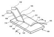
図1は、実施の形態1にかかるマイクロ分析チップの斜視図である。図2は、図1におけるII−II線に沿う断面図である。 FIG. 1 is a perspective view of the micro analysis chip according to the first embodiment. 2 is a cross-sectional view taken along line II-II in FIG.
これらの図に示すように、マイクロ分析チップは、少なくとも2つの注入孔110,111から注入された液体を混合攪拌し、それらの溶液を反応させて分析した後、少なくとも1つの排出孔112から排出する。2つの注入側流路120,121の一方端が各別に2つの注入孔110,111に接続され、それらの他方端は合流している。2つの注入側流路120,121の合流部分から排出側流路122が延び、排出孔112に接続されている。2つの注入側流路120,121が合流する流路上に混合部130が設けられている。混合部130には後述する柱状の突起物が設けられている。 As shown in these figures, the micro-analysis chip mixes and stirs the liquid injected from at least two
マイクロ分析チップ本体100は、凹面の流路122が形成されている基板11および流路120,121,122をシールするための基板10からなる。基板11および基板10に用いられる材料は、例えば、特許文献4(特開2003−149252号公報)に提案されるような、透明または半透明なものが望ましい。なぜなら、マイクロチップの流路122部分を検出部として、チップ内を流れる被写体に励起光を照射し、被写体の蛍光を検出するチップシステムなどへ応用する場合では、反応部で透過した蛍光やUVの検出を行う必要があるからである。透明または半透明なものとして、生産性、再現性の観点から型成型が可能な熱硬化性樹脂、熱可塑性樹脂、フィルム、型成型可能なガラス等が好ましい。なかでも透明性、蛍光特性を考えた場合、シリコン系樹脂、アクリル系樹脂、スチレン系樹脂が好ましい。 The
また、例えば、マイクロ分析チップ流路内で、電気化学測定を行うために、基板10表面に作用極と電極をパターンし、電気化学測定器により電気化学測定を行うことにより、試料液体中の目的物質の濃度感知に用いる場合(例えば、特許文献5(特開2003−285298号公報)参照)では、基板11および基板10の一方または両方が電極形成可能な材料であることが好ましい。電極が形成可能な材料として、生産性、再現性の観点からガラス、シリコン等の基板が好ましい。 In addition, for example, in order to perform electrochemical measurement in the microanalysis chip flow path, the working electrode and the electrode are patterned on the surface of the
基板11の厚みは0.1mm〜5mm程度であり、基板10の厚みは0.01mm〜5mm程度である。注入孔110、111、排出孔112は、直径が10μm以上の貫通穴で良く、基板11または基板10に形成される。注入孔110、111、排出孔112には、FEP、PVC、シリコンなどの軟質ゴム系のチューブ103,104,105やガラス細管、金属微細管などのパイプと接合されるための、直径10μm以上、深さまたは高さが1μmから5mmの突起または孔が形成されている。チューブ103,104には、それぞれポンプ101,102が接続されている。 The thickness of the
基板11への凹凸の形成には、例えば、基板11への直接加工を行う、機械加工による方法、レーザー加工による方法、金型を用いた射出成型、プレス成型、鋳造による方法などがある。なかでも金型を用いる手法は、形状寸法の再現性が高く好ましい。 The formation of the irregularities on the
シリコンまたはガラス等の基板上の流路パターンは、従来一般的に提案されているフォトリソグラフィの手法とエッチング法により形成することができる。 A flow path pattern on a substrate such as silicon or glass can be formed by a conventionally proposed photolithography technique and etching method.
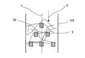
図3は、混合部の液体の流れの様子を示す図である。図3に示すように、混合部130には、流路内に柱状の突起物5が設けられており、柱状の突起物5の背面において、圧力が減少し、圧力差が生じることにより、流体の流れ2が生じ、柱状の突起物5の背面への流れが発生するため、柱状の突起物5の背面において渦流れ50のある領域が発生する。図中、1は中心線を表している。 FIG. 3 is a diagram illustrating a state of liquid flow in the mixing unit. As shown in FIG. 3, the
図4は、図1の攪拌混合部付近の拡大概略図である。図4に示すように、溶液60、溶液61の2液が混合するマイクロチップに利用する場合、柱状の突起物5を配置した後方で渦流れが発生し、この効果により流体の混合攪拌を行うことが可能となる。 FIG. 4 is an enlarged schematic view of the vicinity of the stirring and mixing unit in FIG. As shown in FIG. 4, when used in a microchip in which two
図1に示すマイクロ分析チップ内に作成された流路120、121、122の幅は0.1μm〜5mmの範囲に設定されており、好ましくは10μm〜500μmに設定される。
また、図4に示す流路内に形成された柱状の突起物5の幅は流路120,121、122の幅に対し100分の1から2分の1の範囲に設定されており、好ましくは流路120,121、122の幅に対し20分の1から5分の1に設定される。The widths of the
Further, the width of the
柱状の突起物5は、流路内に1つ形成されていても良く、図5に示すように柱状の突起物5の幅、数を変化させてもよい。このように、複数の柱状の突起物5を形成することで、攪拌混合効果が相乗的に働くようになり、より効果的な混合が可能となる利点が生じる。図中、2は、液体の流れ方向を示す。 One
複数の柱状の突起物5を形成する構成は、上記のように攪拌混合の点では効果的であるが、柱状の突起物5間および柱状の突起物5と流路122の隙間が小さくなるため、流路内の抵抗が大きくなり一定の流量を流すための圧力が大きくなり、結果としてチップが破壊する懸念が生じる。これを防ぐため、図6に示すように柱状の突起物5が形成される流路122において、流路幅41を一時的に流路幅42のように広げることによって流路122内の圧力を低くすることが可能である。このような構成により、複数の柱状の突起物5の形成による効果的な攪拌混合と所定の流量を流すための圧力を低下させるという効果を両立させることができる。 The configuration in which the plurality of
図4に示すような溶液60、溶液61のように2液が混合するマイクロチップにおいて一方の溶液60に、図7に示すように、微小ビーズ70等を含ませ、この微小ビーズ70にもう一方の溶液61に含まれる反応物質71等を反応または固定化する場合、従来の、攪拌混合機構を設けていない一般的な流路では、液体の流れ方向2は、反応部において流路に平行な一方方向のみの流れとなる。このような一方方向の流れのみのマイクロチップでは、微小ビーズ70の表面において、液体の進行方向に向う側の表面と背面において、反応または固定化の偏りが生じる。混合攪拌機構を反応部に用いることにより、反応部において図7に示すような液体は流れ方向2に流れ、渦流れ効果によるビーズ70自体の回転が起こり、ビーズ表面における反応の偏りを小さくすることができる。図中、72は、反応物質固定後のビーズを表している。 In a microchip in which two liquids are mixed such as
金型またはフォトリソグラフィによって流路内に柱状の突起物5を作成する際、コストを軽減するために、金型、マスクの枚数が少なくなるような工程で作成することが望ましいが、微小流路のパターンと柱状の突起物5構造の寸法が大きく異なる場合は2段階以上の工程を行うことにより寸法精度の良い構造が得られる。 In order to reduce the cost when the
図8に示すように、柱状の突起物5の上端と基板10との間に隙間がある場合、障害物がなく圧力が小さくなる隙間部への流体の流れ2が生じ、流路の高さ方向で攪拌混合効果に偏りができるため、隙間を無くすか又は、小さくすることにより深さ方向に生じる攪拌混合効果の偏りを無くすことができる。流路の溝の深さが深く、柱状の突起物の幅が小さくなる場合、アスペクト比の大きな柱状の突起物5を得る必要があるが、樹脂等の型成型においてこのようなアスペクト比の大きな微細部分を加工する場合、微細部分への樹脂の流れが十分には起こりにくくなるため、溝の深さと同じ高さの柱状の突起物を得ることは困難となる。 As shown in FIG. 8, when there is a gap between the upper end of the
このような場合、柱状の突起物と天井との隙間を小さくすることが好ましい。図8に示すように、柱状の突起物5の高さが低く、基板10との間に隙間12が発生している場合、隙間12を小さくする手法として、基板10と基板11を熱融着によって接着行う際に、接着時の温度、圧力を高く設定することにより、図9に示すように基板10の表面の一部を基板11の流路側に突出させることができる。この効果により生じるスペーサ15は、柱状の突起物5と基板10との隙間12を小さくすることが可能となる。 In such a case, it is preferable to reduce the gap between the columnar protrusion and the ceiling. As shown in FIG. 8, when the height of the
図3における柱状の突起物5の表面形状は特に限定しないが、柱状の突起物5の表面に突起部を設けると、突起部の影響により突起物5の後方で、液体の流れに回転方向の流れが発生し、それぞれの突起部で渦効果による攪拌効果が得られる。柱状の突起物5の表面に突起を作成する手法には、例えば図10に示すように、柱状の突起物5の表面に感光性または熱硬化性の樹脂20等を付着させ、硬化する方法が好ましい。付着後の柱状の突起物5および樹脂20の幅は、流路120、121、122の幅に対し100分の1から2分の1の範囲に設定され、好ましくは流路120、121、122の幅に対し20分の1から5分の1に設定される。
(実施の形態2)The surface shape of the
(Embodiment 2)
本発明の別の実施の形態は、図1における攪拌混合部130に別の形態を取ったものである。マイクロ分析チップに用いられる攪拌混合部以外のチップ形状、材料、加工方法は実施の形態1と同様の形態を取っている。 In another embodiment of the present invention, the stirring and mixing
図11に示すように、柱状の突起物5を、流路122に1つ以上形成し、柱状の突起物5によって止められることのできる繊維状物質30などを流路122に流し、柱状の突起物5で塞き止めることにより、流路122内で繊維状物質30をランダムに交差させる。ランダムに配置された繊維状物質30間を流体が流れることにより、後方で渦流れの発生を生じさせる領域ができ、攪拌混合が可能となる。柱状の突起物5で止めるものは、特に限定しないが、繊維状の材料以外に、ビーズ等の球形物質や微粒子、微細チップといったものでも可能である。この際これらのサイズは、柱状の突起物5間の隙間間隔および柱状の突起物5と流路122の壁面との隙間よりも大きくする必要がある。 As shown in FIG. 11, one or more
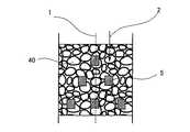
図12に示すように、粘性のある感光性または熱硬化性の樹脂等を柱状の突起物5で塞き止めた後、発泡させることによっても、柱状の突起物5がある箇所に、隙間のある樹脂層40を形成することができる。樹脂層40に形成されたポーラス状の隙間間を流体が流れることにより、流体同士の衝突が起こり溶液の混合攪拌効果を高めることができる。 As shown in FIG. 12, a viscous photosensitive or thermosetting resin or the like is blocked by the
次に、実施例により本発明の説明を行うが、本発明の範囲はこれらの実施例に限定されるものではない。 EXAMPLES Next, although an Example demonstrates this invention, the scope of the present invention is not limited to these Examples.
(実施例1) Example 1
基板としてアクリル系透明樹脂であるPMMA(ポリメチルメタクリレート)樹脂(三菱レーヨン社製アクリライト(登録商標)EX)を準備し、これを外形寸法75mm×35mm×2mmに成型する。次に、金型を用いた加熱プレス成型を行い、図13に示すように、PMMA樹脂片面に流路となる幅300μm、深さ50μmの溝と、溝内に流体の攪拌混合のための幅30μm、長さ30μmの柱状の突起物5を形成し、マイクロ分析チップ流路系を得た。また、このときの幅41は300μm、幅42は390μm、柱状の突起物5の左右の間隔44は75μm、柱状の突起物5と壁面との距離45は75μm、流れ方向の柱状の突起物5同士の間隔46は50μmである。次に機械加工により、基板11側に内径1mmの注入孔および排出孔を形成した。次に、基板11と同様のPMMA樹脂であり、外形寸法75mm×30mm×0.2mmの基板10を準備し、基板11と基板10を熱圧着により接合し、注入孔および排出孔に、PVC(ポリ塩化ビニル)軟質ゴムチューブをシアノアクリレート系の接着剤を用いて接合した。 A PMMA (polymethyl methacrylate) resin (Acrylite (registered trademark) EX manufactured by Mitsubishi Rayon Co., Ltd.), which is an acrylic transparent resin, is prepared as a substrate, and this is molded into an outer dimension of 75 mm × 35 mm × 2 mm. Next, heat press molding using a mold is performed. As shown in FIG. 13, a groove having a width of 300 μm and a depth of 50 μm serving as a flow path on one side of the PMMA resin, and a width for stirring and mixing the fluid in the groove. A
このマイクロ分析チップを用いて図14に示すマイクロ分析チップ分析装置系を構成し、シリンジポンプ102、101を用いて、一方側のチューブ104から純水を30μl/minで注入孔110に注入し、他方側のチューブ103から水溶性のインクを30μl/minで注入孔111に注入した。同様のチップ系において流速を1μl/min、10μl/minに変化させて行った。柱状の突起物5を配置したマイクロ分析チップ系ではいずれの流速条件においても、純水層とインク層の分離は見られず、攪拌効果による溶液の混合が確認された。 Using this microanalysis chip, the microanalysis chip analyzer system shown in FIG. 14 is configured, and syringe pumps 102 and 101 are used to inject pure water from one
(実施例2) (Example 2)
実施例1で用いた図14の流路系において、ガラス繊維(日本ガラス社製ガラスフレーク)を純水と混合した後注入し、図15で示すように柱状の突起物5でガラス繊維30を固定化した流路系を得た。作成したマイクロ分析チップを用い、図14に示すように、シリンジポンプ102、101を用いて、一方側のチューブ104から純水を30μl/minで注入孔110に注入し、他方側のチューブ103から水溶性のインクを30μl/minで注入孔111に注入した。同様のチップ系において流速を1μl/min、10μl/minに変化させて行った。柱状の突起物5を配置したマイクロ分析チップ系ではいずれの流速条件においても、純水層とインク層の分離は見られず、攪拌効果による溶液の混合が確認された。
(比較例)In the flow path system of FIG. 14 used in Example 1, glass fibers (glass flakes manufactured by Nippon Glass Co., Ltd.) were mixed with pure water and then injected. As shown in FIG. An immobilized flow path system was obtained. Using the prepared microanalysis chip, as shown in FIG. 14, pure water is injected into the
(Comparative example)
実施例1に用いたマイクロチップ分析装置系において、柱状の突起物を設けず、図16に示すような直線の流路に対し約3倍の長さになるように流路を折り曲げた構造202を作成し、一方側のチューブ104から純水を30μl/minで注入孔110に注入し、他方側のチューブ103から水溶性のインクを30μl/minで注入孔111に注入した。同様のチップ系において流速を1μl/min、10μl/minに変化させて行った。流速条件10μl/min、30μl/minでは、排出孔112までの流路において、拡散に必要な十分な流路距離が得られておらず、純水層とインク層の分離が確認された。流速1μl/minにおいては、純水とインクの混合層であるグレーゾーンが流路中心付近で観察できたが、拡散に必要な十分な距離が得られず、純水層壁面までのインクの拡散は観察されなかった。 In the microchip analyzer system used in Example 1, a
実施例に示したようなマイクロ分析チップでは、流路形成と同時に攪拌混合機構部を形成でき、チップ面積が限られたマイクロ分析チップ設計においても、突起部を形成することにより、混合攪拌を効率よく行うことが可能となり、簡便な混合攪拌機構として、バイオセンサ、アレルゲンセンサー、核酸チップ、μTAS等のチップ利用分野に利用できる。 In the micro analysis chip as shown in the examples, the stirring and mixing mechanism can be formed simultaneously with the flow path formation, and even in the micro analysis chip design with a limited chip area, the mixing and stirring can be efficiently performed by forming the protrusion. It can be performed well and can be used as a simple mixing and stirring mechanism in the field of chip utilization such as biosensors, allergen sensors, nucleic acid chips, and μTAS.
1 中心線
2 流体の流れ方向
5 柱状の突起物
10 基板
11 基板
15 スペーサー
20 樹脂
30 繊維
40 樹脂層
41、42 流路の幅
43 柱状の突起物5と基板10との隙間
44、45、46 流路と柱状の突起物5の隙間の幅
50 渦流れ
60 溶液1
61 溶液2
70 ビーズ
71 反応物質
72 反応物質固定後のビーズ
100 マイクロ分析チップ本体
101、102 ポンプ
103、104,105 チューブ
110、111、210、211 注入孔
112、212 排出孔
120、121、122 流路
130 攪拌混合部
201、202 流路の折れ曲がり部
DESCRIPTION OF
61
70
Claims (14)
Translated fromJapaneseそれらの一方端が各別に前記2つの注入孔に接続され、それらの他方端が合流する少なくとも2つの注入側流路と、
前記2つの注入側流路の合流部分から延び、前記排出孔に接続される排出側流路と、
前記2つの注入側流路の合流する流路上に設けられた混合部と、
前記混合部に設けられ、液体の混合攪拌効果を高めるための少なくとも1つの柱状の突起物とを備えたマイクロ分析チップ。A micro-analysis chip that mixes and stirs liquids injected from at least two injection holes, reacts and analyzes the solutions, and then discharges the liquids from at least one discharge hole.
At least two injection-side flow paths, one end of which is connected to the two injection holes separately and the other end of which joins;
A discharge-side flow path extending from a merged portion of the two injection-side flow paths and connected to the discharge hole;
A mixing section provided on the flow path where the two injection-side flow paths merge;
A micro-analysis chip provided in the mixing unit and provided with at least one columnar protrusion for enhancing the effect of mixing and stirring liquids.
それらの一方端が各別に前記2つの注入孔に接続され、それらの他方端が合流する少なくとも2つの注入側流路と、
前記2つの注入側流路の合流部分から延び、前記排出孔に接続される排出側流路と、
前記2つの注入側流路が合流する流路上に設けられた混合部とを備え、
前記混合部に、液体の混合攪拌効果を高めるための繊維状物質が固定されているマイクロ分析チップ。A micro-analysis chip that mixes and stirs liquids injected from at least two injection holes, reacts and analyzes the solutions, and then discharges the liquids from at least one discharge hole.
At least two injection-side flow paths, one end of which is connected to the two injection holes separately and the other end of which joins;
A discharge-side flow path extending from a merged portion of the two injection-side flow paths and connected to the discharge hole;
A mixing section provided on the flow path where the two injection-side flow paths merge,
A microanalysis chip in which a fibrous substance for enhancing the mixing and stirring effect of a liquid is fixed to the mixing unit.
それらの一方端が各別に前記2つの注入孔に接続され、それらの他方端が合流する少なくとも2つの注入側流路と、
前記2つの注入側流路の合流部分から延び、前記排出孔に接続される排出側流路と、
前記2つの注入側流路が合流する流路上に設けられた混合部とを備え、
前記混合部にポーラス状物質を固定化していることを特徴とするマイクロ分析チップ。A micro-analysis chip that mixes and stirs liquids injected from at least two injection holes, reacts and analyzes the solutions, and then discharges the liquids from at least one discharge hole.
At least two injection-side flow paths, one end of which is connected to the two injection holes separately and the other end of which joins;
A discharge-side flow path extending from a merged portion of the two injection-side flow paths and connected to the discharge hole;
A mixing section provided on the flow path where the two injection-side flow paths merge,
A micro-analysis chip, wherein a porous substance is immobilized in the mixing part.
The immobilization of the porous substance is obtained by forming columnar protrusions in the mixing portion, blocking the viscous foamable resin with the columnar protrusions, and then foaming. The micro analysis chip according to claim 12.
Priority Applications (1)
| Application Number | Priority Date | Filing Date | Title |
|---|---|---|---|
| JP2005202940AJP2007024522A (en) | 2005-07-12 | 2005-07-12 | Micro analysis chip |
Applications Claiming Priority (1)
| Application Number | Priority Date | Filing Date | Title |
|---|---|---|---|
| JP2005202940AJP2007024522A (en) | 2005-07-12 | 2005-07-12 | Micro analysis chip |
Publications (1)
| Publication Number | Publication Date |
|---|---|
| JP2007024522Atrue JP2007024522A (en) | 2007-02-01 |
Family
ID=37785510
Family Applications (1)
| Application Number | Title | Priority Date | Filing Date |
|---|---|---|---|
| JP2005202940AWithdrawnJP2007024522A (en) | 2005-07-12 | 2005-07-12 | Micro analysis chip |
Country Status (1)
| Country | Link |
|---|---|
| JP (1) | JP2007024522A (en) |
Cited By (11)
| Publication number | Priority date | Publication date | Assignee | Title |
|---|---|---|---|---|
| WO2009069656A1 (en) | 2007-11-26 | 2009-06-04 | Fujimori Kogyo Co., Ltd. | Microchip and blood monitoring device |
| JP2012132879A (en)* | 2010-12-24 | 2012-07-12 | Sekisui Chem Co Ltd | Microfluid device, and system and method for detecting microorganism contaminant |
| JP2014038018A (en)* | 2012-08-14 | 2014-02-27 | Alps Electric Co Ltd | Channel chip |
| US8796031B2 (en) | 2010-02-10 | 2014-08-05 | Fujimori Kogyo Co., Ltd. | Microchip for platelet examination and platelet examination device using same |
| US20160103046A1 (en)* | 2014-10-14 | 2016-04-14 | Becton, Dickinson And Company | Blood Sample Management Using Open Cell Foam |
| JP2017122617A (en)* | 2016-01-06 | 2017-07-13 | シャープ株式会社 | Container for component analysis and component analysis system |
| CN113877645A (en)* | 2021-10-29 | 2022-01-04 | 深圳迈瑞动物医疗科技有限公司 | Microfluidic Chip |
| CN114534814A (en)* | 2022-03-29 | 2022-05-27 | 天津诺迈科技有限公司 | Micro-fluidic chip |
| WO2022114129A1 (en)* | 2020-11-27 | 2022-06-02 | 藤森工業株式会社 | Method for manufacturing microchip for blood coagulation test |
| CN118341494A (en)* | 2024-01-11 | 2024-07-16 | 杭州联川生物技术股份有限公司 | A liquid adding method for microfluidic chip |
| WO2025069832A1 (en)* | 2023-09-29 | 2025-04-03 | 京セラ株式会社 | Flow path substrate |
- 2005
- 2005-07-12JPJP2005202940Apatent/JP2007024522A/ennot_activeWithdrawn
Cited By (18)
| Publication number | Priority date | Publication date | Assignee | Title |
|---|---|---|---|---|
| JPWO2009069656A1 (en)* | 2007-11-26 | 2011-04-14 | 藤森工業株式会社 | Microchip and blood observation device |
| EP2228657A4 (en)* | 2007-11-26 | 2011-07-06 | Fujimori Kogyo Co | MICROCHIP AND BLOOD MONITORING DEVICE |
| US8425840B2 (en) | 2007-11-26 | 2013-04-23 | Fujimori Kogyo Co., Ltd. | Microchip and blood monitoring device |
| WO2009069656A1 (en) | 2007-11-26 | 2009-06-04 | Fujimori Kogyo Co., Ltd. | Microchip and blood monitoring device |
| US8796031B2 (en) | 2010-02-10 | 2014-08-05 | Fujimori Kogyo Co., Ltd. | Microchip for platelet examination and platelet examination device using same |
| JP2012132879A (en)* | 2010-12-24 | 2012-07-12 | Sekisui Chem Co Ltd | Microfluid device, and system and method for detecting microorganism contaminant |
| JP2014038018A (en)* | 2012-08-14 | 2014-02-27 | Alps Electric Co Ltd | Channel chip |
| US11298061B2 (en) | 2014-10-14 | 2022-04-12 | Becton, Dickinson And Company | Blood sample management using open cell foam |
| US20160103046A1 (en)* | 2014-10-14 | 2016-04-14 | Becton, Dickinson And Company | Blood Sample Management Using Open Cell Foam |
| JP2018049026A (en)* | 2014-10-14 | 2018-03-29 | ベクトン・ディキンソン・アンド・カンパニーBecton, Dickinson And Company | Blood sample management using open cell foam |
| EP4338668A1 (en)* | 2014-10-14 | 2024-03-20 | Becton, Dickinson and Company | Blood sample management using open cell foam |
| JP2017122617A (en)* | 2016-01-06 | 2017-07-13 | シャープ株式会社 | Container for component analysis and component analysis system |
| WO2022114129A1 (en)* | 2020-11-27 | 2022-06-02 | 藤森工業株式会社 | Method for manufacturing microchip for blood coagulation test |
| CN113877645A (en)* | 2021-10-29 | 2022-01-04 | 深圳迈瑞动物医疗科技有限公司 | Microfluidic Chip |
| CN114534814A (en)* | 2022-03-29 | 2022-05-27 | 天津诺迈科技有限公司 | Micro-fluidic chip |
| CN114534814B (en)* | 2022-03-29 | 2024-09-20 | 天津诺迈科技有限公司 | Microfluidic chip |
| WO2025069832A1 (en)* | 2023-09-29 | 2025-04-03 | 京セラ株式会社 | Flow path substrate |
| CN118341494A (en)* | 2024-01-11 | 2024-07-16 | 杭州联川生物技术股份有限公司 | A liquid adding method for microfluidic chip |
Similar Documents
| Publication | Publication Date | Title |
|---|---|---|
| JP4792664B2 (en) | Mixing method, mixing mechanism, micromixer and microchip having the mixing mechanism | |
| Ahmed et al. | A fast microfluidic mixer based on acoustically driven sidewall-trapped microbubbles | |
| EP1463579B1 (en) | Microfluidic aperture mixers | |
| US6890093B2 (en) | Multi-stream microfludic mixers | |
| CN103946548B (en) | There is the microfluidic device of deformable valve | |
| JP4683066B2 (en) | Liquid mixing mechanism | |
| JP3775305B2 (en) | Liquid mixing mechanism and liquid mixing method | |
| KR100941069B1 (en) | Microfluidic dilution device | |
| EP1855114A1 (en) | Microchannel and microfluid chip | |
| US20100189601A1 (en) | Capillary | |
| EP1893739A2 (en) | Recirculating microfluidic device and methods of use | |
| JP2007024522A (en) | Micro analysis chip | |
| Greenwood et al. | Sample manipulation in micro total analytical systems | |
| JP2008082961A (en) | Microchannel device | |
| JP3974531B2 (en) | Microchannel mixing method and microchannel apparatus | |
| JP4415944B2 (en) | Liquid mixing mechanism | |
| KR20150105856A (en) | Micro Mixer Using Taylor Gortler Vortex and Manufacturing Method Thereof | |
| US20150017023A1 (en) | Apparatuses and methods for modulating fluids using acoustically oscillating solid structures | |
| US20060034735A1 (en) | Microreactor | |
| JP2018151184A (en) | Structure and manufacturing method of structure | |
| JP2009264858A (en) | Living body analyzing device, and method for quantifying and agitating sample using it | |
| JP5267241B2 (en) | Manufacturing method of flow channel device | |
| JP2005030999A (en) | Reaction mechanism | |
| JP2009213983A (en) | Micro-mixer | |
| CN115315314A (en) | Chips for Fluid Analysis |
Legal Events
| Date | Code | Title | Description |
|---|---|---|---|
| A300 | Withdrawal of application because of no request for examination | Free format text:JAPANESE INTERMEDIATE CODE: A300 Effective date:20081007 |